
Systematic Development of a Powder Deposition System for an Open Selective Laser Sintering Machine Using Analytic Hierarchy Process


Abstract
:1. Introduction
2. State of the Art
2.1. Design Proceedures in the Manufacturing Domain
2.2. Powder Deposition Methods
2.2.1. Mechanical Methods
2.2.2. Electrostatic Methods
2.2.3. Vibratory Methods
2.2.4. Other Methods
2.3. Research Gaps
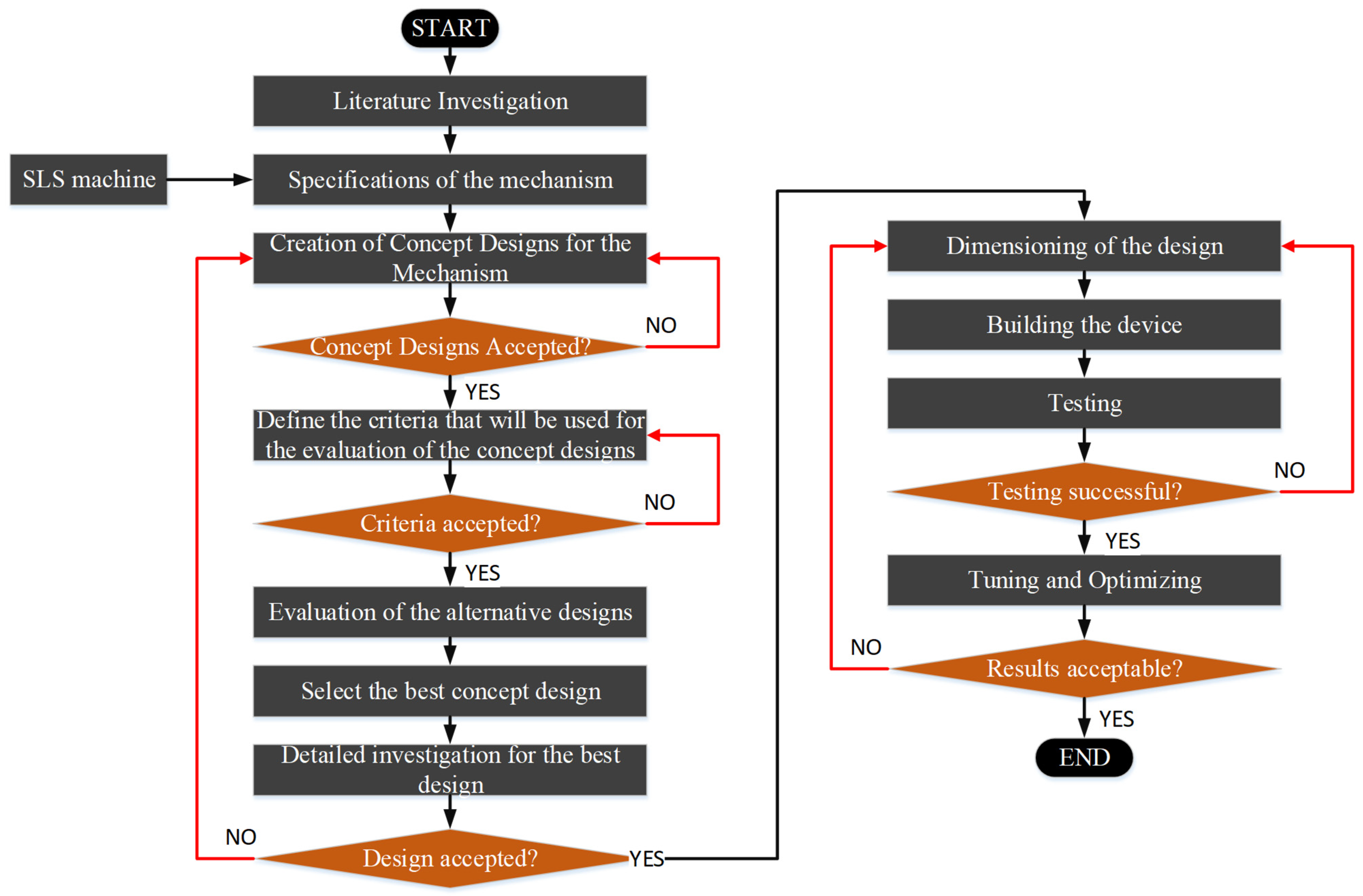
3. Methodology
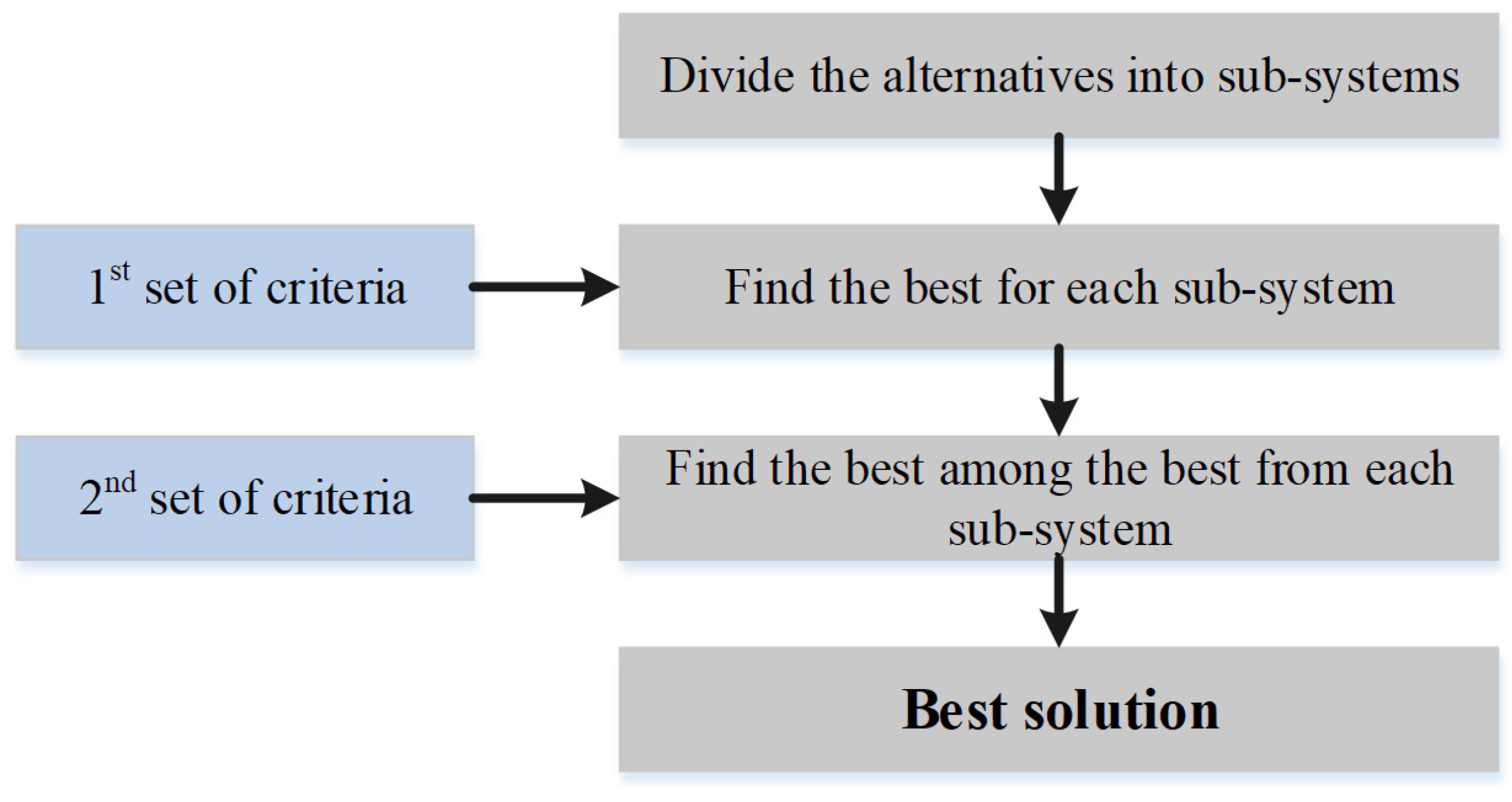
3.1. Analytic Hierarchy Process (AHP)
3.2. Evaluation Criteria
4. PDS Concept Development
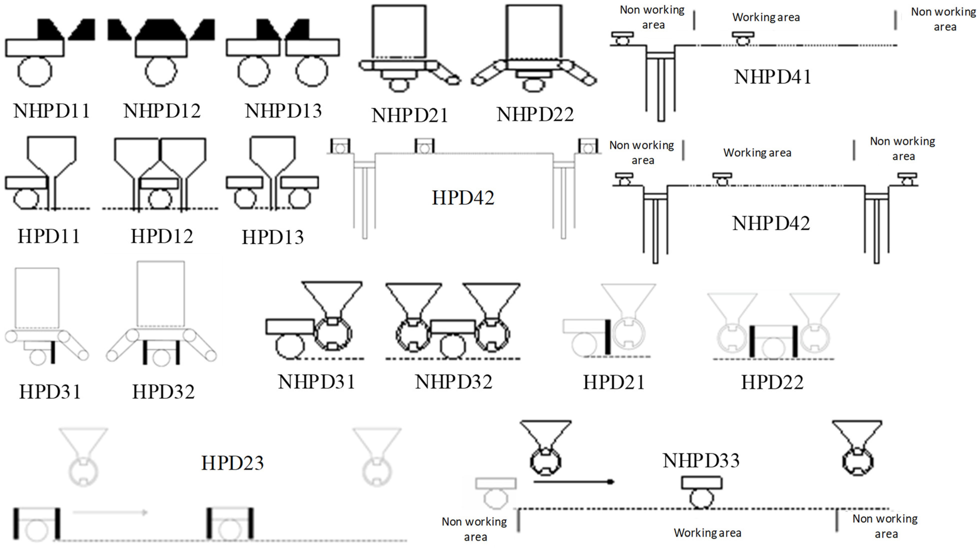
4.1. Generation and Analysis of Alternatives
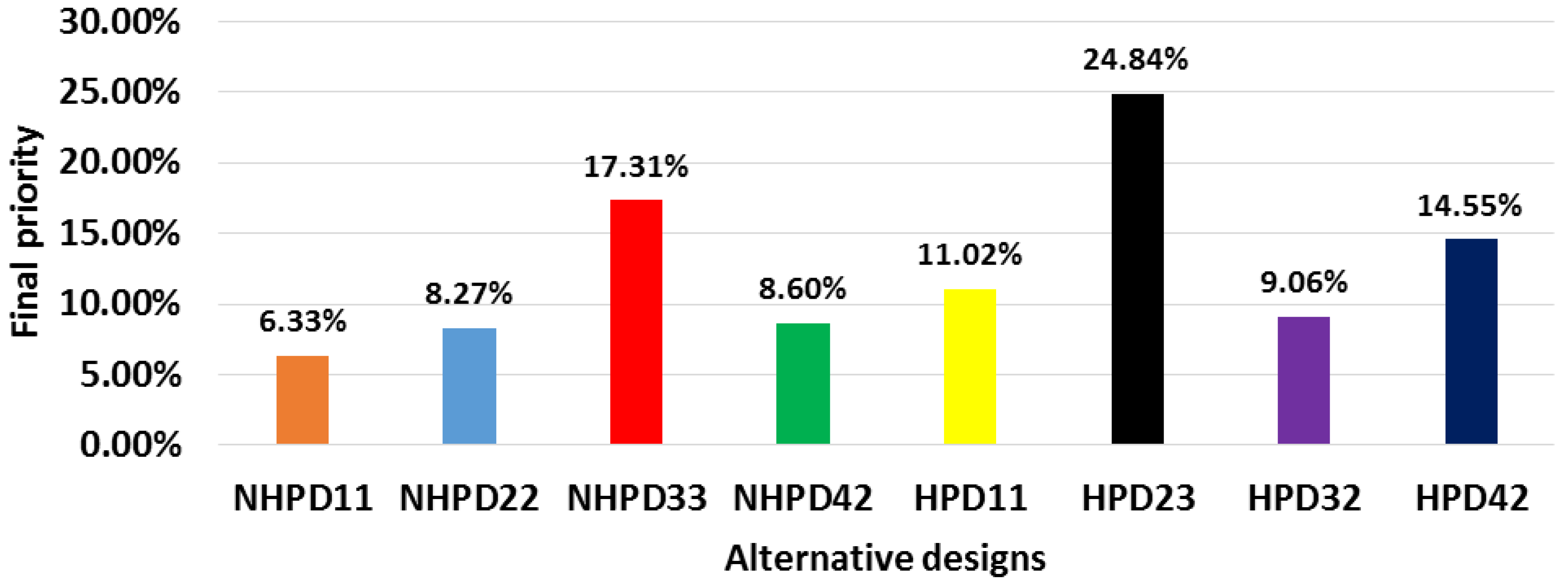
4.2. Evaluation of Alternatives
- NHPD22 with priority 53.47% followed by NHPD21 with 46.15%.
- NHPD33 with priority 44.37% among the three custom-made dosing mechanism designs.
- NHPD41 with priority 53.54%.
- Designs HPD11, HPD23 and HPD42 were selected yet marginally amongst the alternative designs of each category. Finally, HPD32 design was selected with 53.47%.
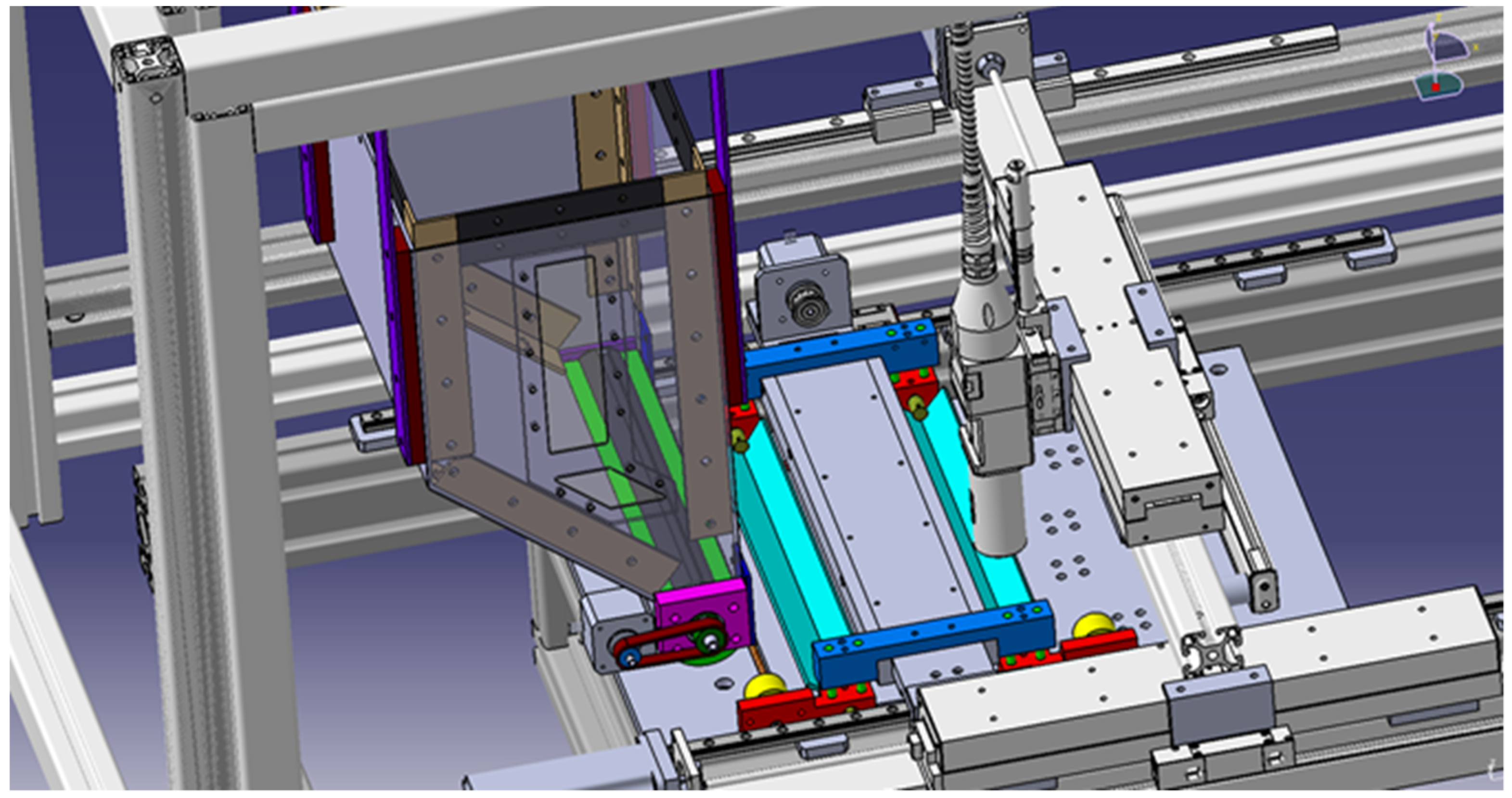
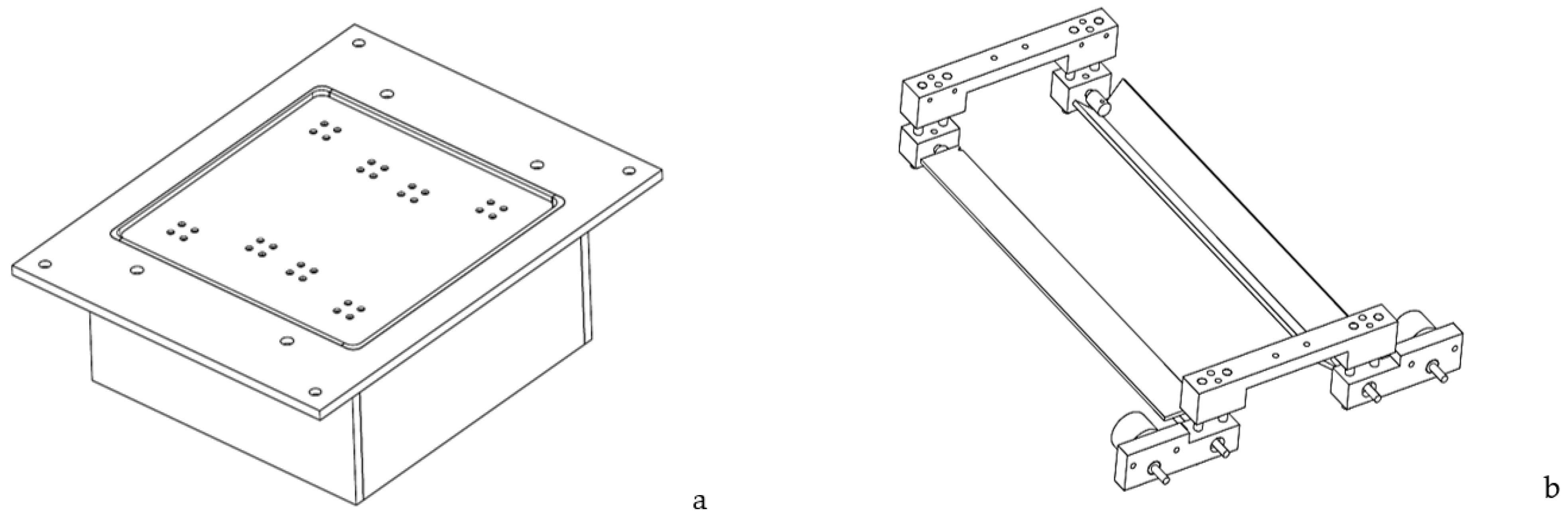
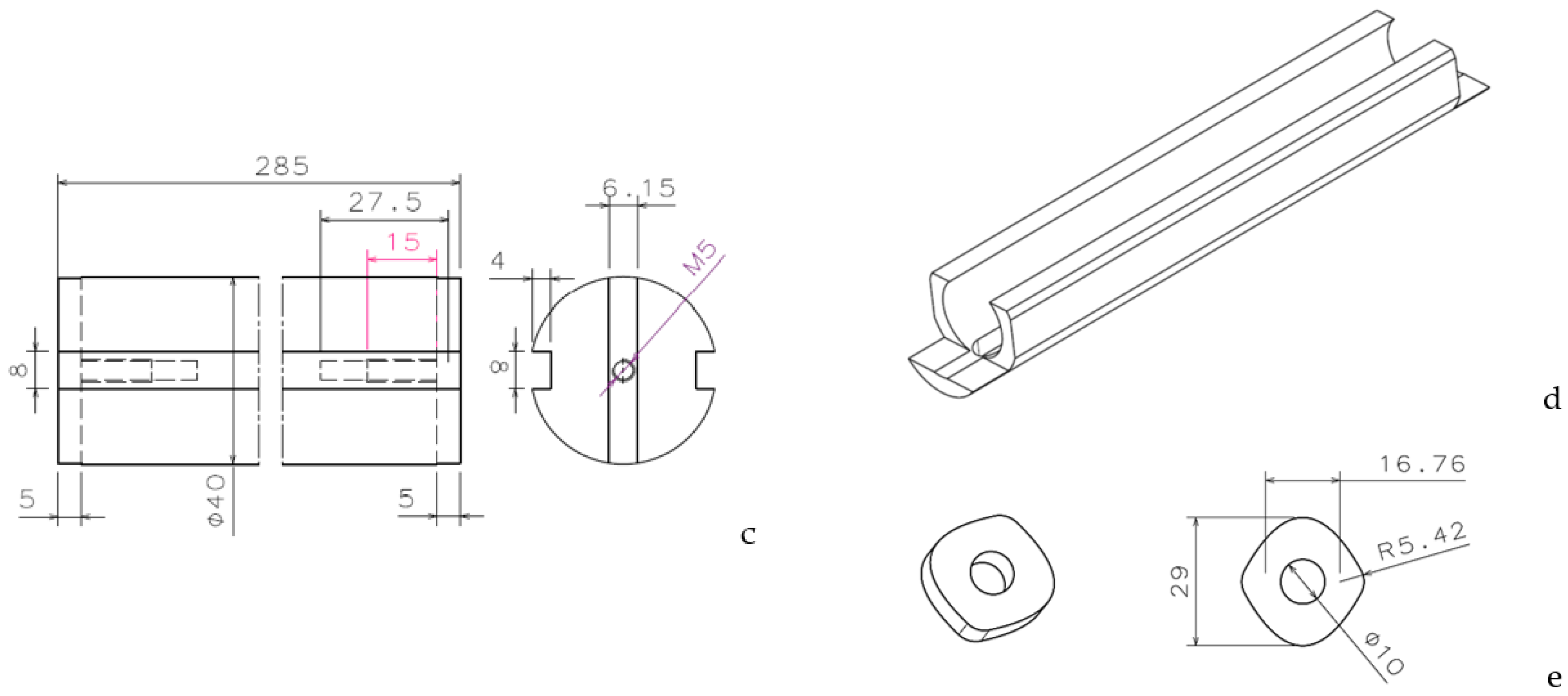
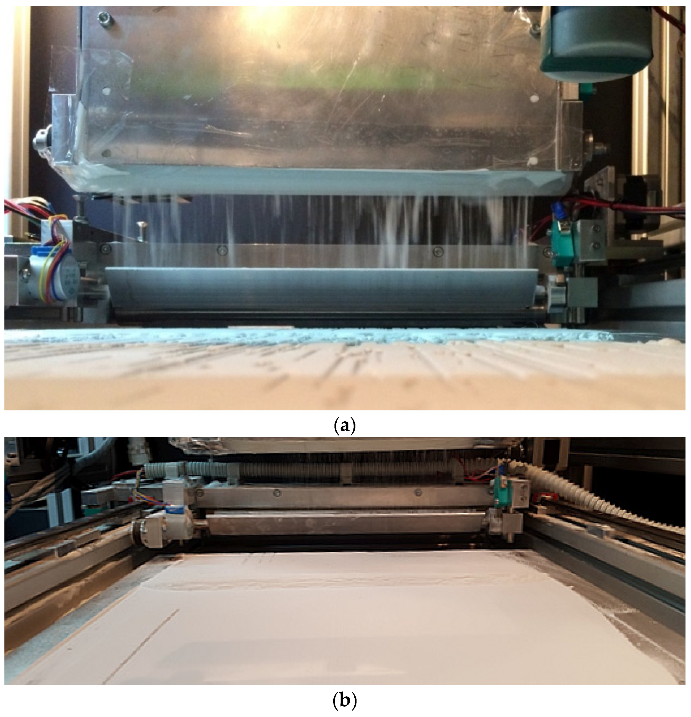
5. PDS Detailed Design and Implementation
6. Conclusions
Author Contributions
Funding
Conflicts of Interest
Appendix A

| Cr11 | NHPD21 | NHPD22 | Priority Vector | Cr14 | NHPD21 | NHPD22 | Priority Vector |
| NHPD21 | 1 | 1/5 | 0.1667 | NHPD21 | 1 | 2 | 0.6667 |
| NHPD22 | 5 | 1 | 0.8333 | NHPD22 | 1/2 | 1 | 0.3333 |
| λmax = 2, n = 2, CR = 0 < 1 table consistent | λmax = 2, n = 2, CR = 0 < 1 table consistent | ||||||
| Cr12 | NHPD21 | NHPD22 | Priority Vector | Cr15 | NHPD21 | NHPD22 | Priority Vector |
| NHPD21 | 1 | 3 | 0.7500 | NHPD21 | 1 | 4 | 0.8000 |
| NHPD22 | 1/3 | 1 | 0.2500 | NHPD22 | 1/4 | 1 | 0.2000 |
| λmax = 2, n = 2, CR = 0 < 1 table consistent | λmax = 2, n = 2, CR = 0 < 1 table consistent | ||||||
| Cr13 | NHPD21 | NHPD22 | Priority Vector | Cr16 | NHPD21 | NHPD22 | Priority Vector |
| NHPD21 | 1 | 2 | 0.6667 | NHPD21 | 1 | 1 | 0.5000 |
| NHPD22 | 1/2 | 1 | 0.3333 | NHPD22 | 1 | 1 | 0.5000 |
| λmax = 2, n = 2, CR = 0 < 1 table consistent | λmax = 2, n = 2, CR = 0 < 1 table consistent | ||||||
| Decision matrix NHPD2 | |||||||
| Criteria | |||||||
| Cr11 | Cr12 | Cr13 | Cr14 | Cr15 | Cr16 | Final priority | |
| Alt. | 0.4057 | 0.0467 | 0.275 | 0.1237 | 0.0744 | 0.0744 | |
| NHPD21 | 0.1667 | 0.7500 | 0.6667 | 0.6667 | 0.8000 | 0.5000 | 0.4615 |
| NHPD22 | 0.8333 | 0.2500 | 0.3333 | 0.3333 | 0.2000 | 0.5000 | 0.5347 |
| Cr11 | NHPD31 | NHPD32 | NHPD33 | Priority Vector | Cr14 | NHPD31 | NHPD32 | NHPD33 | Priority Vector | ||||||
| NHPD31 | 1 | 1/6 | 1/6 | 0.0769 | NHPD31 | 1 | 4 | 2 | 0.5714 | ||||||
| NHPD32 | 6 | 1 | 1 | 0.4615 | NHPD32 | 1/4 | 1 | 1/2 | 0.1429 | ||||||
| NHPD33 | 6 | 1 | 1 | 0.4615 | NHPD33 | 1/2 | 2 | 1 | 0.2857 | ||||||
| λmax = 3, n = 3, CR = 0 < 1 table consistent | λmax = 3, n = 3, CR = 0 < 1 table consistent | ||||||||||||||
| Cr12 | NHPD31 | NHPD32 | NHPD33 | Priority Vector | Cr15 | NHPD31 | NHPD32 | NHPD33 | Priority Vector | ||||||
| NHPD31 | 1 | 4 | 1/3 | 0.2628 | NHPD31 | 1 | 3 | 1/4 | 0.2255 | ||||||
| NHPD32 | 1/4 | 1 | 1/7 | 0.0786 | NHPD32 | 1/3 | 1 | 1/5 | 0.1007 | ||||||
| NHPD33 | 3 | 7 | 1 | 0.6586 | NHPD33 | 4 | 5 | 1 | 0.6738 | ||||||
| λmax = 3.0324, n = 3, CR = 0.0279 < 1 table consistent | λmax = 3.0858, n = 3, CR = 0.0739 < 1 table consistent | ||||||||||||||
| Cr13 | NHPD31 | NHPD32 | NHPD33 | Priority Vector | Cr16 | NHPD31 | NHPD32 | NHPD33 | Priority Vector | ||||||
| NHPD31 | 1 | 5 | 2 | 0.5816 | NHPD31 | 1 | 1/4 | 1/9 | 0.0633 | ||||||
| NHPD32 | 1/5 | 1 | 1/3 | 0.1095 | NHPD32 | 4 | 1 | 1/5 | 0.1939 | ||||||
| NHPD33 | 1/2 | 3 | 1 | 0.3090 | NHPD33 | 9 | 5 | 1 | 0.7429 | ||||||
| λmax = 3.0037, n = 3, CR = 0.0032 < 1 table consistent | λmax = 3.0713, n = 3, CR = 0.0614 < 1 table consistent | ||||||||||||||
| Decision matrix NHPD3 | |||||||||||||||
| Criteria | |||||||||||||||
| Cr11 | Cr12 | Cr13 | Cr14 | Cr15 | Cr16 | Final priority | |||||||||
| Alt. | 0.4057 | 0.0467 | 0.275 | 0.1237 | 0.0744 | 0.0744 | |||||||||
| NHPD31 | 0.0769 | 0.2628 | 0.5816 | 0.5714 | 0.2255 | 0.0633 | 0.2955 | ||||||||
| NHPD32 | 0.4615 | 0.0786 | 0.1095 | 0.1429 | 0.1007 | 0.1939 | 0.2606 | ||||||||
| NHPD33 | 0.4615 | 0.6586 | 0.3090 | 0.2857 | 0.6738 | 0.7429 | 0.4437 | ||||||||
| Cr11 | NHPD41 | NHPD42 | Priority Vector | Cr14 | NHPD41 | NHPD42 | Priority Vector |
| NHPD41 | 1 | 1/5 | 0.1667 | NHPD41 | 1 | 3 | 0.7500 |
| NHPD42 | 5 | 1 | 0.8333 | NHPD42 | 1/3 | 1 | 0.2500 |
| λmax = 2, n = 2, CR = 0 < 1 table consistent | λmax = 2, n = 2, CR = 0 < 1 table consistent | ||||||
| Cr12 | NHPD41 | NHPD42 | Priority Vector | Cr15 | NHPD41 | NHPD42 | Priority Vector |
| NHPD41 | 1 | 1 | 0.5000 | NHPD41 | 1 | 2 | 0.6667 |
| NHPD42 | 1 | 1 | 0.5000 | NHPD42 | 1/2 | 1 | 0.3333 |
| λmax = 2, n = 2, CR = 0 < 1 table consistent | λmax = 2, n = 2, CR = 0 < 1 table consistent | ||||||
| Cr13 | NHPD41 | NHPD42 | Priority Vector | Cr16 | NHPD41 | NHPD42 | Priority Vector |
| NHPD41 | 1 | 3 | 0.7500 | NHPD41 | 1 | 1/2 | 0.3333 |
| NHPD42 | 1/3 | 1 | 0.2500 | NHPD42 | 2 | 1 | 0.6667 |
| λmax = 2, n = 2, CR = 0 < 1 table consistent | λmax = 2, n = 2, CR = 0 < 1 table consistent | ||||||
| Decision matrix NHPD4 | |||||||
| Criteria | |||||||
| Cr11 | Cr12 | Cr13 | Cr14 | Cr15 | Cr16 | Final priority | |
| Alt. | 0.4057 | 0.0467 | 0.275 | 0.1237 | 0.0744 | 0.0744 | |
| NHPD41 | 0.1667 | 0.5000 | 0.7500 | 0.7500 | 0.6667 | 0.3333 | 0.4644 |
| NHPD42 | 0.8333 | 0.5000 | 0.2500 | 0.2500 | 0.3333 | 0.6667 | 0.5354 |
| Cr11 | HPD11 | HPD12 | HPD13 | Priority Vector | Cr14 | HPD11 | HPD12 | HPD13 | Priority Vector | ||||||
| HPD11 | 1 | 1/6 | 1/6 | 0.0769 | HPD11 | 1 | 5 | 3 | 0.6370 | ||||||
| HPD12 | 6 | 1 | 1 | 0.4615 | HPD12 | 1/5 | 1 | 1/3 | 0.1047 | ||||||
| HPD13 | 6 | 1 | 1 | 0.4615 | HPD13 | 1/3 | 3 | 1 | 0.2583 | ||||||
| λmax = 3, n = 3, CR = 0 < 1 table consistent | λmax = 3.0385, n = 3, CR = 0.0332 < 1 table consistent | ||||||||||||||
| Cr12 | HPD11 | HPD12 | HPD13 | Priority Vector | Cr15 | HPD11 | HPD12 | HPD13 | Priority Vector | ||||||
| HPD11 | 1 | 5 | 1/4 | 0.2370 | HPD11 | 1 | 6 | 4 | 0.7010 | ||||||
| HPD12 | 1/5 | 1 | 1/8 | 0.0643 | HPD12 | 1/6 | 1 | 1/2 | 0.1061 | ||||||
| HPD13 | 4 | 8 | 1 | 0.6986 | HPD13 | 1/4 | 2 | 1 | 0.1929 | ||||||
| λmax = 3.0324, n = 3, CR = 0.0279 < 1 table consistent | λmax = 3.0092, n = 3, CR = 0.0079 < 1 table consistent | ||||||||||||||
| Cr13 | HPD11 | HPD12 | HPD13 | Priority Vector | Cr16 | HPD11 | HPD12 | HPD13 | Priority Vector | ||||||
| HPD11 | 1 | 3 | 4 | 0.6250 | HPD11 | 1 | 1/7 | 1 | 0.1111 | ||||||
| HPD12 | 1/3 | 1 | 2 | 0.2385 | HPD12 | 7 | 1 | 7 | 0.7778 | ||||||
| HPD13 | 1/4 | 1/2 | 1 | 0.1365 | HPD13 | 1 | 1/7 | 1 | 0.1111 | ||||||
| λmax = 3.0037, n = 3, CR = 0.0032 < 1 table consistent | λmax = 3, n = 3, CR = 0 < 1 table consistent | ||||||||||||||
| Decision matrix HPD1 | |||||||||||||||
| Criteria | |||||||||||||||
| Cr11 | Cr12 | Cr13 | Cr14 | Cr15 | Cr16 | Final priority | |||||||||
| Alt. | 0.4057 | 0.0467 | 0.275 | 0.1237 | 0.0744 | 0.0744 | |||||||||
| HPD11 | 0.0769 | 0.2370 | 0.6250 | 0.6370 | 0.7010 | 0.1111 | 0.3533 | ||||||||
| HPD12 | 0.4615 | 0.0643 | 0.2385 | 0.1047 | 0.1061 | 0.7778 | 0.3345 | ||||||||
| HPD13 | 0.4615 | 0.6986 | 0.1365 | 0.2583 | 0.1929 | 0.1111 | 0.3119 | ||||||||
| Cr11 | HPD21 | HPD22 | HPD23 | Priority Vector | Cr14 | HPD21 | HPD22 | HPD23 | Priority Vector | ||||||
| HPD21 | 1 | 1/6 | 1/6 | 0.0769 | HPD21 | 1 | 4 | 2 | 0.5714 | ||||||
| HPD22 | 6 | 1 | 1 | 0.4615 | HPD22 | 1/4 | 1 | 1/2 | 0.1429 | ||||||
| HPD23 | 6 | 1 | 1 | 0.4615 | HPD23 | 1/2 | 2 | 1 | 0.2857 | ||||||
| λmax = 3, n = 3, CR = 0 < 1 table consistent | λmax = 3.0385, n = 3, CR = 0.0332 < 1 table consistent | ||||||||||||||
| Cr12 | HPD21 | HPD22 | HPD23 | Priority Vector | Cr15 | HPD21 | HPD22 | HPD23 | Priority Vector | ||||||
| HPD21 | 1 | 4 | 1/3 | 0.2628 | HPD21 | 1 | 6 | 3 | 0.6548 | ||||||
| HPD22 | 1/4 | 1 | 1/7 | 0.0786 | HPD22 | 1/6 | 1 | 1/3 | 0.0953 | ||||||
| HPD23 | 3 | 7 | 1 | 0.6586 | HPD23 | 1/3 | 3 | 1 | 0.2499 | ||||||
| λmax = 3.0324, n = 3, CR = 0.0279 < 1 table consistent | λmax = 3.0183, n = 3, CR = 0.0158 < 1 table consistent | ||||||||||||||
| Cr13 | HPD21 | HPD22 | HPD23 | Priority Vector | Cr16 | HPD21 | HPD22 | HPD23 | Priority Vector | ||||||
| HPD21 | 1 | 5 | 2 | 0.5816 | HPD21 | 1 | 1/4 | 1/9 | 0.0633 | ||||||
| HPD22 | 1/5 | 1 | 1/3 | 0.1095 | HPD22 | 4 | 1 | 1/5 | 0.1939 | ||||||
| HPD23 | 1/2 | 3 | 1 | 0.3090 | HPD23 | 9 | 5 | 1 | 0.7429 | ||||||
| λmax = 3.0037, n = 3, CR = 0.0032 < 1 table consistent | λmax = 3, n = 3, CR = 0 < 1 table consistent | ||||||||||||||
| Decision matrix HPD2 | |||||||||||||||
| Criteria | |||||||||||||||
| Cr11 | Cr12 | Cr13 | Cr14 | Cr15 | Cr16 | Final priority | |||||||||
| Alt. | 0.4057 | 0.0467 | 0.275 | 0.1237 | 0.0744 | 0.0744 | |||||||||
| HPD21 | 0.0769 | 0.2628 | 0.5816 | 0.5714 | 0.6548 | 0.0633 | 0.3275 | ||||||||
| HPD22 | 0.4615 | 0.0786 | 0.1095 | 0.1429 | 0.0953 | 0.1939 | 0.2602 | ||||||||
| HPD23 | 0.4615 | 0.6586 | 0.3090 | 0.2857 | 0.2499 | 0.7429 | 0.4121 | ||||||||
| Cr11 | HPD31 | HPD32 | Priority Vector | Cr14 | HPD31 | HPD32 | Priority Vector |
| HPD31 | 1 | 1/5 | 0.1667 | HPD31 | 1 | 2 | 0.6667 |
| HPD32 | 5 | 1 | 0.8333 | HPD32 | 1/2 | 1 | 0.3333 |
| λmax = 2, n = 2, CR = 0 < 1 table consistent | λmax = 2, n = 2, CR = 0 < 1 table consistent | ||||||
| Cr12 | HPD31 | HPD32 | Priority Vector | Cr15 | HPD31 | HPD32 | Priority Vector |
| HPD31 | 1 | 3 | 0.7500 | HPD31 | 1 | 4 | 0.8000 |
| HPD32 | 1/3 | 1 | 0.2500 | HPD32 | 1/4 | 1 | 0.2000 |
| λmax = 2, n = 2, CR = 0 < 1 table consistent | λmax = 2, n = 2, CR = 0 < 1 table consistent | ||||||
| Cr13 | HPD31 | HPD32 | Priority Vector | Cr16 | HPD31 | HPD32 | Priority Vector |
| HPD31 | 1 | 2 | 0.6667 | HPD31 | 1 | 1 | 0.5000 |
| HPD32 | 1/2 | 1 | 0.3333 | HPD32 | 1 | 1 | 0.5000 |
| λmax = 2, n = 2, CR = 0 < 1 table consistent | λmax = 2, n = 2, CR = 0 < 1 table consistent | ||||||
| Decision matrix NHPD2 | |||||||
| Criteria | |||||||
| Cr11 | Cr12 | Cr13 | Cr14 | Cr15 | Cr16 | Final priority | |
| Alt. | 0.4057 | 0.0467 | 0.275 | 0.1237 | 0.0744 | 0.0744 | |
| HPD31 | 0.1667 | 0.7500 | 0.6667 | 0.6667 | 0.8000 | 0.5000 | 0.4615 |
| HPD32 | 0.8333 | 0.2500 | 0.3333 | 0.3333 | 0.2000 | 0.5000 | 0.5347 |
| Cr11 | HPD41 | HPD42 | Priority Vector | Cr14 | HPD41 | HPD42 | Priority Vector |
| HPD41 | 1 | 1/5 | 0.1667 | HPD41 | 1 | 3 | 0.7500 |
| HPD42 | 5 | 1 | 0.8333 | HPD42 | 1/3 | 1 | 0.2500 |
| λmax = 2, n = 2, CR = 0 < 1 table consistent | λmax = 2, n = 2, CR = 0 < 1 table consistent | ||||||
| Cr12 | HPD41 | HPD42 | Priority Vector | Cr15 | HPD41 | HPD42 | Priority Vector |
| HPD41 | 1 | 1 | 0.5000 | HPD41 | 1 | 2 | 0.6667 |
| HPD42 | 1 | 1 | 0.5000 | HPD42 | 1/2 | 1 | 0.3333 |
| λmax = 2, n = 2, CR = 0 < 1 table consistent | λmax = 2, n = 2, CR = 0 < 1 table consistent | ||||||
| Cr13 | HPD41 | HPD42 | Priority Vector | Cr16 | HPD41 | HPD42 | Priority Vector |
| HPD41 | 1 | 3 | 0.7500 | HPD41 | 1 | 1/2 | 0.3333 |
| HPD42 | 1/3 | 1 | 0.2500 | HPD42 | 2 | 1 | 0.6667 |
| λmax = 2, n = 2, CR = 0 < 1 table consistent | λmax = 2, n = 2, CR = 0 < 1 table consistent | ||||||
| Decision matrix NHPD4 | |||||||
| Criteria | |||||||
| Cr11 | Cr12 | Cr13 | Cr14 | Cr15 | Cr16 | Final priority | |
| Alt. | 0.4057 | 0.0467 | 0.275 | 0.1237 | 0.0744 | 0.0744 | |
| HPD41 | 0.1667 | 0.5000 | 0.7500 | 0.7500 | 0.6667 | 0.3333 | 0.4644 |
| HPD42 | 0.8333 | 0.5000 | 0.2500 | 0.2500 | 0.3333 | 0.6667 | 0.5354 |
Appendix B
| Cr21 | NHPD11 | NHPD22 | NHPD33 | NHPD42 | HPD11 | HPD23 | HPD32 | HPD42 | Priority Vector |
|---|---|---|---|---|---|---|---|---|---|
| NHPD11 | 1 | 1/2 | 1/2 | 1/2 | 1/5 | 1/8 | 1/6 | 1/7 | 0.0256 |
| NHPD22 | 2 | 1 | 1 | 1 | 1/4 | 1/7 | 1/5 | 1/6 | 0.0385 |
| NHPD33 | 2 | 1 | 1 | 1 | 1/4 | 1/7 | 1/5 | 1/6 | 0.0385 |
| NHPD42 | 2 | 1 | 1 | 1 | 1/4 | 1/7 | 1/5 | 1/6 | 0.0385 |
| HPD11 | 5 | 4 | 4 | 4 | 1 | 1/4 | 1/2 | 1/3 | 0.1159 |
| HPD23 | 8 | 7 | 7 | 7 | 4 | 1 | 3 | 2 | 0.3392 |
| HPD32 | 6 | 5 | 5 | 5 | 2 | 1/3 | 1 | 1/2 | 0.1655 |
| HPD42 | 7 | 6 | 6 | 6 | 3 | 1/2 | 2 | 1 | 0.2382 |
| λmax = 8.1452, n = 8, CR = 0.0147 < 1 table consistent | |||||||||
| Cr22 | NHPD11 | NHPD22 | NHPD33 | NHPD42 | HPD11 | HPD23 | HPD32 | HPD42 | Priority Vector |
|---|---|---|---|---|---|---|---|---|---|
| NHPD11 | 1 | 2 | 1 | 2 | 1 | 1/3 | 1 | 1/2 | 0.1027 |
| NHPD22 | 1/2 | 1 | 1/2 | 1 | 1/2 | 1/4 | 1/2 | 1/3 | 0.0563 |
| NHPD33 | 1 | 2 | 1 | 2 | 1 | 1/3 | 1 | 1/2 | 0.1027 |
| NHPD42 | 1/2 | 1 | 1/2 | 1 | 1/2 | 1/4 | 1/2 | 1/3 | 0.0563 |
| HPD11 | 1 | 2 | 1 | 2 | 1 | 1/3 | 1 | 1/2 | 0.1027 |
| HPD23 | 3 | 4 | 3 | 4 | 3 | 1 | 3 | 2 | 0.2915 |
| HPD32 | 1 | 2 | 1 | 2 | 1 | 1/3 | 1 | 1/2 | 0.1027 |
| HPD42 | 2 | 3 | 2 | 3 | 2 | 1/2 | 2 | 1 | 0.1853 |
| λmax = 8.0415, n = 8, CR = 0.0042 < 1 table consistent | |||||||||
| Cr23 | NHPD11 | NHPD22 | NHPD33 | NHPD42 | HPD11 | HPD23 | HPD32 | HPD42 | Priority Vector |
|---|---|---|---|---|---|---|---|---|---|
| NHPD11 | 1 | 1/2 | 1 | 2 | 1 | 2 | 2 | 3 | 0.1504 |
| NHPD22 | 2 | 1 | 2 | 3 | 2 | 3 | 3 | 4 | 0.2587 |
| NHPD33 | 1 | 1/2 | 1 | 2 | 1 | 2 | 2 | 3 | 0.1504 |
| NHPD42 | 1/2 | 1/3 | 1/2 | 1 | 1/2 | 1 | 1 | 2 | 0.0808 |
| HPD11 | 1 | 1/2 | 1 | 2 | 1 | 2 | 2 | 3 | 0.1504 |
| HPD23 | 1/2 | 1/3 | 1/2 | 1 | 1/2 | 1 | 1 | 2 | 0.0808 |
| HPD32 | 1/2 | 1/3 | 1/2 | 1 | 1/2 | 1 | 1 | 2 | 0.0808 |
| HPD42 | 1/3 | 1/4 | 1/3 | 1/2 | 1/3 | 1/2 | 1/2 | 1 | 0.0478 |
| λmax = 8.0389, n = 8, CR = 0.0039 < 1 table consistent | |||||||||
| Cr24 | NHPD11 | NHPD22 | NHPD33 | NHPD42 | HPD11 | HPD23 | HPD32 | HPD42 | Priority Vector |
|---|---|---|---|---|---|---|---|---|---|
| NHPD11 | 1 | 1/2 | 1/4 | 1/3 | 1/5 | 1/3 | 1 | 1/3 | 0.0426 |
| NHPD22 | 2 | 1 | 1/3 | 1/2 | 1/4 | 1/2 | 2 | 1/2 | 0.0699 |
| NHPD33 | 4 | 3 | 1 | 2 | 1/2 | 2 | 4 | 2 | 0.1937 |
| NHPD42 | 3 | 2 | 1/2 | 1 | 1/3 | 1 | 1/3 | 1 | 0.0948 |
| HPD11 | 5 | 4 | 2 | 3 | 1 | 3 | 5 | 3 | 0.2930 |
| HPD23 | 3 | 2 | 1/2 | 1 | 1/3 | 1 | 3 | 1 | 0.1171 |
| HPD32 | 1 | 1/2 | 1/4 | 3 | 1/5 | 1/3 | 1 | 1/3 | 0.0720 |
| HPD42 | 3 | 2 | 1/2 | 1 | 1/3 | 1 | 3 | 1 | 0.1171 |
| λmax = 8.6000, n = 8, CR = 0.0608 < 1 table consistent | |||||||||
| Cr25 | NHPD11 | NHPD22 | NHPD33 | NHPD42 | HPD11 | HPD23 | HPD32 | HPD42 | Priority Vector |
|---|---|---|---|---|---|---|---|---|---|
| NHPD11 | 1 | 1 | 1/6 | 1/4 | 1/5 | 1/5 | 1 | 1/3 | 0.0361 |
| NHPD22 | 1 | 1 | 1/6 | 1/4 | 1/5 | 1/5 | 1 | 1/3 | 0.0361 |
| NHPD33 | 6 | 6 | 1 | 3 | 2 | 2 | 6 | 4 | 0.2978 |
| NHPD42 | 4 | 4 | 1/3 | 1 | 1/2 | 1/2 | 4 | 2 | 0.1247 |
| HPD11 | 5 | 5 | 1/2 | 2 | 1 | 1 | 5 | 3 | 0.1933 |
| HPD23 | 5 | 5 | 1/2 | 2 | 1 | 1 | 5 | 3 | 0.1933 |
| HPD32 | 1 | 1 | 1/6 | 1/4 | 1/5 | 1/5 | 1 | 1/3 | 0.0361 |
| HPD42 | 3 | 3 | 1/4 | 1/2 | 1/3 | 1/3 | 3 | 1 | 0.0827 |
| λmax = 8.1444, n = 8, CR = 0.0146 < 1 table consistent | |||||||||
| Cr26 | NHPD11 | NHPD22 | NHPD33 | NHPD42 | HPD11 | HPD23 | HPD32 | HPD42 | Priority Vector |
|---|---|---|---|---|---|---|---|---|---|
| NHPD11 | 1 | 1 | 1/5 | 1/2 | 2 | 1/4 | 2 | 1 | 0.0689 |
| NHPD22 | 1 | 1 | 1/5 | 1/2 | 2 | 1/4 | 2 | 1 | 0.0689 |
| NHPD33 | 5 | 5 | 1 | 4 | 6 | 2 | 6 | 5 | 0.3486 |
| NHPD42 | 2 | 2 | 1/4 | 1 | 3 | 1/3 | 3 | 2 | 0.1162 |
| HPD11 | 1/2 | 1/2 | 1/6 | 1/3 | 1 | 1/5 | 1 | 1/2 | 0.0408 |
| HPD23 | 4 | 4 | 1/2 | 3 | 5 | 1 | 5 | 4 | 0.2469 |
| HPD32 | 1/2 | 1/2 | 1/6 | 1/3 | 1 | 1/5 | 1 | 1/2 | 0.0408 |
| HPD42 | 1 | 1 | 1/5 | 1/2 | 2 | 1/4 | 2 | 1 | 0.0689 |
| λmax = 8.1192, n = 8, CR = 0.0121 < 1 table consistent | |||||||||
| Cr27 | NHPD11 | NHPD22 | NHPD33 | NHPD42 | HPD11 | HPD23 | HPD32 | HPD42 | Priority Vector |
|---|---|---|---|---|---|---|---|---|---|
| NHPD11 | 1 | 1 | 1/6 | 1/2 | 1 | 1/6 | 1 | 1/2 | 0.0469 |
| NHPD22 | 1 | 1 | 1/6 | 1/2 | 1 | 1/6 | 1 | 1/2 | 0.0469 |
| NHPD33 | 6 | 6 | 1 | 5 | 6 | 1 | 6 | 5 | 0.3229 |
| NHPD42 | 2 | 2 | 1/5 | 1 | 2 | 1/5 | 2 | 1 | 0.0832 |
| HPD11 | 1 | 1 | 1/6 | 1/2 | 1 | 1/6 | 1 | 1/2 | 0.0469 |
| HPD23 | 6 | 6 | 1 | 5 | 6 | 1 | 6 | 5 | 0.3229 |
| HPD32 | 1 | 1 | 1/6 | 1/2 | 1 | 1/6 | 1 | 1/2 | 0.0469 |
| HPD42 | 2 | 2 | 1/5 | 1 | 2 | 1/5 | 2 | 1 | 0.0832 |
| λmax = 8.0656, n = 8, CR = 0.0066 < 1 table consistent | |||||||||
| Cr28 | NHPD11 | NHPD22 | NHPD33 | NHPD42 | HPD11 | HPD23 | HPD32 | HPD42 | Priority Vector |
|---|---|---|---|---|---|---|---|---|---|
| NHPD11 | 1 | 1 | 1/7 | 1/7 | 1 | 1/7 | 1 | 1/7 | 0.0312 |
| NHPD22 | 1 | 1 | 1/7 | 1/7 | 1 | 1/7 | 1 | 1/7 | 0.0313 |
| NHPD33 | 7 | 7 | 1 | 1 | 7 | 1 | 7 | 1 | 0.2188 |
| NHPD42 | 7 | 7 | 1 | 1 | 7 | 1 | 7 | 1 | 0.2188 |
| HPD11 | 1 | 1 | 1/7 | 1/7 | 1 | 1/7 | 1 | 1/7 | 0.0312 |
| HPD23 | 7 | 7 | 1 | 1 | 7 | 1 | 7 | 1 | 0.2188 |
| HPD32 | 1 | 1 | 1/7 | 1/7 | 1 | 1/7 | 1 | 1/7 | 0.0312 |
| HPD42 | 7 | 7 | 1 | 1 | 7 | 1 | 7 | 1 | 0.2188 |
| λmax = 8, n = 8, CR = 0 < 1 table consistent | |||||||||
References
- Cai, W.; Lai, K.-H.; Liu, C.; Wei, F.; Ma, M.; Jia, S.; Jiang, Z.; Lv, L. Promoting sustainability of manufacturing industry through the lean energy-saving and emission-reduction strategy. Sci. Total Environ. 2019, 665, 23–32. [Google Scholar] [CrossRef] [PubMed]
- Fu, Y.; Wang, L.; Li, L. Conceptual design scheme automatic generation and decision-making considering green demand. Procedia Manuf. 2020, 43, 407–414. [Google Scholar] [CrossRef]
- Liu, Z.; Zhao, D.; Wang, P.; Yan, M.; Yang, C.; Chen, Z.; Lu, J.; Lu, Z. Additive manufacturing of metals: Microstructure evolution and multistage control. J. Mater. Sci. Technol. 2021, 100, 224–236. [Google Scholar] [CrossRef]
- Gorsse, S.; Hutchinson, C.; Gouné, M.; Banerjee, R. Additive manufacturing of metals: A brief review of the characteristic microstructures and properties of steels, Ti-6Al-4V and high-entropy alloys. Sci. Technol. Adv. Mater. 2017, 18, 584–610. [Google Scholar] [CrossRef] [Green Version]
- Bajaj, P.; Hariharan, A.; Kini, A.; Kürnsteiner, P.; Raabe, D.; Jägle, E.A. Steels in additive manufacturing: A review of their microstructure and properties. Mater. Sci. Eng. A 2020, 772, 138633. [Google Scholar] [CrossRef]
- DebRoy, T.; Wei, H.L.; Zuback, J.S.; Mukherjee, T.; Elmer, J.W.; Milewski, J.O.; Beese, A.M.; Wilson-Heid, A.; De, A.; Zhang, W. Additive manufacturing of metallic components—Process, structure and properties. Prog. Mater. Sci. 2018, 92, 112–224. [Google Scholar] [CrossRef]
- Dilberoglu, U.M.; Gharehpapagh, B.; Yaman, U.; Dolen, M. The role of additive manufacturing in the era of industry 4.0. Procedia Manuf. 2017, 11, 545–554. [Google Scholar] [CrossRef]
- Wohlers, T.; Campbell, R.; Diegel, O.; Kowen, J.; Huff, R.; Mostow, N. Wohlers Report 2021: Additive Manufacturing and 3D Printing State of the Industry; Wohlers Associates: Fort Collins, CO, USA, 2021. [Google Scholar]
- Karapatis, P. A Sub-Process Approach of Selective Laser Sintering; EPFL: Lausanne, Switzerland, 2002. [Google Scholar] [CrossRef]
- Kolosov, S.; Vansteenkiste, G.; Boudeau, N.; Gelin, J.C.; Boillat, E. Homogeneity aspects in selective laser sintering (SLS). J. Mater. Process. Technol. 2006, 177, 348–351. [Google Scholar] [CrossRef]
- Richardson, J.F.; Harker, J.H.; Backhurst, J.R. Chemical Engineering: Particle Technology and Separation Processes, 5th ed.; Elsevier: Amsterdam, The Netherlands, 2013; Volume 2, pp. 1–1156. [Google Scholar] [CrossRef]
- Matel, G.; Claussen, N.; Hausner, H.H. Influence of Relative Humidity on Flow of Metal and Ceramic Powders. In Modern Developments in Powder Metallurgy; Springer: Boston, MA, USA, 1974. [Google Scholar]
- Kamalakkannan, S.; Kulatunga, A.K. Optimization of eco-design decisions using a parametric life cycle assessment. Sustain. Prod. Consum. 2021, 27, 1297–1316. [Google Scholar] [CrossRef]
- Erenay, B.; Suer, G.A.; Huang, J.; Maddisetty, S. Comparison of layered cellular manufacturing system design approaches. Comput. Ind. Eng. 2015, 85, 346–358. [Google Scholar] [CrossRef]
- Mourtzis, D.; Doukas, M.; Psarommatis, F. Manufacturing network design for mass customisation using a genetic algorithm and an intelligent search method. Procedia CIRP 2013, 7, 37–42. [Google Scholar] [CrossRef] [Green Version]
- Mourtzis, D.; Doukas, M.; Psarommatis, F. Design and operation of manufacturing networks for mass customization. J. Manuf. Syst. 2015, 36, 274–286. [Google Scholar] [CrossRef]
- Psarommatis, F.; May, G.; Dreyfus, P.-A.; Kiritsis, D. Zero defect manufacturing: State-of-the-art review, shortcomings and future directions in research. Int. J. Prod. Res. 2020, 58, 1–17. [Google Scholar] [CrossRef]
- Psarommatis, F.; Sousa, J.; Mendonça, P.; Kiritsis, D.; Mendonça, J.P. Zero-defect manufacturing the approach for higher manufacturing sustainability in the era of industry 4.0: A position paper. Int. J. Prod. Res. 2021, 1–19. [Google Scholar] [CrossRef]
- Psarommatis, F. A generic methodology and a digital twin for zero defect manufacturing (ZDM) performance mapping towards design for ZDM. J. Manuf. Syst. 2021, 59, 507–521. [Google Scholar] [CrossRef]
- Yao, L.; Zou, Z. A one-dimensional design methodology for supercritical carbon dioxide Brayton cycles: Integration of cycle conceptual design and components preliminary design. Appl. Energy 2020, 276, 115354. [Google Scholar] [CrossRef]
- Soufi, Z.; David, P.; Yahouni, Z. A methodology for the selection of Material Handling Equipment in manufacturing systems. IFAC-PapersOnLine 2021, 54, 122–127. [Google Scholar] [CrossRef]
- Napoleone, A.; Brunoe, T.D.; Andersen, A.-L.; Nielsen, K. A tool for the comparison of concept designs of reconfigurable manufacturing systems. Procedia CIRP 2021, 104, 1125–1130. [Google Scholar] [CrossRef]
- Van der Schueren, B.; Kruth, J.P. Powder deposition in selective metal powder sintering. Rapid Prototyp. J. 1995, 1, 23–31. [Google Scholar] [CrossRef]
- Brackpool, J.L. The effect of material characteristics on the compaction behaviour of metal powders. In Modern Developments in Powder Metallurgy; Springer: Berlin/Heidelberg, Germany, 1971; pp. 423–435. [Google Scholar] [CrossRef]
- Soe, S.P. Quantitative analysis on SLS part curling using EOS P700 machine. J. Mater. Process. Technol. 2012, 212, 2433–2442. [Google Scholar] [CrossRef]
- Budding, A.; Vaneker, T.H.J. New strategies for powder compaction in powder-based rapid prototyping techniques. Procedia CIRP 2013, 6, 527–532. [Google Scholar] [CrossRef] [Green Version]
- Feng, P.; Meng, X.; Chen, J.F.; Ye, L. Mechanical properties of structures 3D printed with cementitious powders. Constr. Build. Mater. 2015, 93, 486–497. [Google Scholar] [CrossRef] [Green Version]
- Peyre, P.; Rouchausse, Y.; Defauchy, D.; Regnier, G.; Régnier, G. Experimental and numerical analysis of the selective laser sintering (SLS) of PA12 and PEKK semi-crystalline polymers. J. Mater. Process. Technol. 2015, 225, 326–336. [Google Scholar] [CrossRef]
- Drummer, D.; Drexler, M.; Kühnlein, F. Effects on the density distribution of SLS-parts. Phys. Procedia 2012, 39, 500–508. [Google Scholar] [CrossRef] [Green Version]
- Bailey, A.G. The science and technology of electrostatic powder spraying, transport and coating. J. Electrost. 1998, 45, 85–120. [Google Scholar] [CrossRef]
- Kadonaga, M.; Katoh, T.; Takahashi, T. A study of non-uniform charging by charging roller with DC voltage. J. Imaging Sci. Technol. 1999, 43, 274–279. [Google Scholar]
- Kumar, A.V.; Zhang, H. Electrophotographic powder deposition for freeform fabrication. In Proceedings of the 10th Solid Freeform Fabrication Symposium (SFF), Austin, TX, USA, 9–11 August 1999. [Google Scholar]
- Stichel, T.; Brachmann, C.; Raths, M.; Dechet, M.; Schmidt, J.; Peukert, W.; Frick, T.; Roth, S. Electrophotographic multilayer powder pattern deposition for additive manufacturing. JOM 2019, 72, 1366–1375. [Google Scholar] [CrossRef]
- Nowak, E.R.; Knight, J.B.; Ben-Naim, E.; Jaeger, H.M.; Nagel, S.R. Density fluctuations in vibrated granular materials. Phys. Rev. E 1998, 57, 1971–1982. [Google Scholar] [CrossRef]
- Yang, S.; Evans, J. Metering and dispensing of powder; the quest for new solid freeforming techniques. Powder Technol. 2007, 178, 56–72. [Google Scholar] [CrossRef]
- Barker, G.; Mehta, A. Transient phenomena, self-diffusion, and orientational effects in vibrated powders. Phys. Rev. E 1993, 47, 184–188. [Google Scholar] [CrossRef] [PubMed]
- Saker, A.; Cares-Pacheco, M.-G.; Marchal, P.; Falk, V. Powders flowability assessment in granular compaction: What about the consistency of Hausner ratio? Powder Technol. 2019, 354, 52–63. [Google Scholar] [CrossRef]
- Staffa, K.H.; Jahn, J.; Claussen, N. Flowability of powders under the influence of vibrations. Powder Metall. 1977, 9, 20–23. [Google Scholar]
- Matsusaka, S.; Yamamoto, K.; Masuda, H. Micro-feeding of a fine powder using a vibrating capillary tube. Adv. Powder Technol. 1996, 7, 141–151. [Google Scholar] [CrossRef]
- Xue, J.; Schiano, S.; Zhong, W.; Chen, L.; Wu, C.Y. Determination of the flow/no-flow transition from a flat bottom hopper. Powder Technol. 2019, 358, 55–61. [Google Scholar] [CrossRef]
- Engisch, W.E.; Muzzio, F.J. Method for characterization of loss-in-weight feeder equipment. Powder Technol. 2012, 228, 395–403. [Google Scholar] [CrossRef]
- Imole, O.I.; Krijgsman, D.; Weinhart, T.; Magnanimo, V.; Montes, B.E.C.; Ramaioli, M.; Luding, S. Experiments and discrete element simulation of the dosing of cohesive powders in a simplified geometry. Powder Technol. 2016, 287, 108–120. [Google Scholar] [CrossRef] [Green Version]
- Matsusaka, S.; Urakawa, M.; Masuda, H. Micro-feeding of fine powders using a capillary tube with ultrasonic vibration. Adv. Powder Technol. 1995, 6, 283–293. [Google Scholar] [CrossRef] [Green Version]
- Zhou, C.; Wang, J.; Guo, C.; Zhao, C.; Jiang, G.; Dong, T.; Jiang, F. Numerical study of the ultrasonic impact on additive manufactured parts. Int. J. Mech. Sci. 2021, 197, 106334. [Google Scholar] [CrossRef]
- Gorunov, A.I. Additive manufacturing of Ti6Al4V parts using ultrasonic assisted direct energy deposition. J. Manuf. Process. 2020, 59, 545–556. [Google Scholar] [CrossRef]
- Wei, C.; Gu, H.; Zhang, X.; Chueh, Y.H.; Li, L. Hybrid ultrasonic and mini-motor vibration-induced irregularly shaped powder delivery for multiple materials additive manufacturing. Addit. Manuf. 2020, 33, 101138. [Google Scholar] [CrossRef]
- Yang, Y.; Li, X. Experimental and analytical study of ultrasoAnic micro powder feeding. J. Phys. D Appl. Phys. 2003, 36, 1349–1354. [Google Scholar] [CrossRef]
- Yang, S.; Evans, J.R.G. Flow rate of metal powders at reduced and elevated air pressure. Powder Technol. 2005, 154, 95–98. [Google Scholar] [CrossRef]
- Wu, Y.; Du, J.; Choy, K.L.; Hench, L.L. Fabrication of titanium dioxide ceramics by laser sintering green layers prepared via aerosol assisted spray deposition. Mater. Sci. Eng. A 2007, 454, 148–155. [Google Scholar] [CrossRef]
- Zhang, K.; Liu, W.; Shang, X. Research on the processing experiments of laser metal deposition shaping. Opt. Laser Technol. 2007, 39, 549–557. [Google Scholar] [CrossRef] [Green Version]
- Wang, Z.; Zhang, A.; Shang, X. 3-D design and numerical simulation of two-phase flow in the laser rapid prototyping coaxial powder delivery system. Tsinghua Sci. Technol. 2009, 14, 200–205. [Google Scholar] [CrossRef]
- Psarommatis, F. Development of a Powder Management Mechanism for an SLS Machine. Master’s Thesis, National Technical University of Athens, Athens, Greece, 2016. [Google Scholar] [CrossRef]
- Saaty, R.W. The analytic hierarchy process—What it is and how it is used. Math. Model. 1987, 9, 161–176. [Google Scholar] [CrossRef] [Green Version]
- Psarommatis, F.; Zheng, X.; Kiritsis, D. A two-layer criteria evaluation approach for re-scheduling efficiently semi-automated assembly lines with high number of rush orders. Procedia CIRP 2021, 97, 172–177. [Google Scholar] [CrossRef]
- Saaty, T.L. A scaling method for priorities in hierarchical structures. J. Math. Psychol. 1977, 15, 234–281. [Google Scholar] [CrossRef]
- Pasalopoulos, S.; Avrampos, P.; Vosniakos, G.-C. Surface quality evaluation of non-sintered powder layers in selective laser sintering by 3D scanning. Procedia Manuf. 2020, 51, 748–754. [Google Scholar] [CrossRef]


| Alternative Judgment Matrices | Priority Vector | Criteria Judgment Matrix | Priority Vector | ||||||||
|---|---|---|---|---|---|---|---|---|---|---|---|
| CrN | Al1 | Al2 | … | AlM | Cr1 | Cr2 | … | CrN | |||
| Al1 | 1 | a21 | … | aM1 | PV1N | Cr1 | 1 | c21 | … | cN1 | PVCr1 |
| Al2 | 1/a21 | 1 | … | aM2 | PV2N | Cr2 | 1/c21 | 1 | … | cN2 | PVCr2 |
| ⋮ | ⋮ | ⋮ | 1 | ⋮ | ⋮ | ⋮ | ⋮ | ⋮ | 1 | ⋮ | ⋮ |
| AlM | 1/aM1 | 1/aM2 | … | 1 | PVMN | CrN | 1/cN1 | 1/cN2 | … | 1 | PVCrN |
| Intensity of Importance | Definition |
|---|---|
| 1 | Equal importance |
| 3 | Weak importance of one over another |
| 5 | Essential or strong importance |
| 7 | Demonstrated importance |
| 9 | Absolute importance |
| 2, 4, 6, 8 | Intermediate values between two adjacent judgments |
| Principal Eigenvector i (for i = 1, 2, …, M + 1) | Normalized Principal Eigenvector | Consistency (CI) | Consistency Ratio (CR) |
|---|---|---|---|
| n | 1 | 2 | 3 | 4 | 5 | 6 | 7 | 8 | 9 | 10 | 11 | 12 | 13 | 14 | 15 |
|---|---|---|---|---|---|---|---|---|---|---|---|---|---|---|---|
| RCI | 0.00 | 0.00 | 0.58 | 0.90 | 1.12 | 1.24 | 1.32 | 1.41 | 1.45 | 1.49 | 1.51 | 1.48 | 1.56 | 1.57 | 1.59 |
| Alternative Judgment Matrices | Final Priority | ||||
|---|---|---|---|---|---|
| Cr1 | Cr2 | … | CrN | ||
| PVCr1 | PVCr2 | PVCrN | |||
| Al1 | PV11 | PV21 | … | PV1N | FP1 |
| Al2 | PV12 | PV22 | … | PV2N | FP2 |
| ⋮ | ⋮ | ⋮ | ⋮ | ⋮ | ⋮ |
| AlM | PV1M | PV2M | … | PVMN | FPM |
| 1st | 2nd | Criteria | Description |
|---|---|---|---|
| Cr11 | - | Process cycle time | The estimated cycle time for the deposition of a powder layer. |
| Cr12 | - | Weight on the roller | The estimated weight on the roller, which can affect the surface quality. |
| Cr13 | Cr23 | Cost | The estimated cost for the fabrication of the mechanism. |
| Cr14 | Cr24 | Manufacturability | The easiness for manufacturing for the mechanism. |
| Cr15 | Cr25 | Complexity | The estimated complexity of the mechanism. |
| Cr16 | Cr28 | Standalone possibility | Need for peripheral devices (during the powder deposition procedure). |
| - | Cr21 | Surface quality | The estimated surface quality of the powder layer. |
| - | Cr22 | Experimental interest | The interest for experimentation. |
| - | Cr26 | Adaptability | How easy the mechanism can be adapted to the existing SLS machine. |
| - | Cr27 | Geometric constraints | Number and type of geometric constraints to consider in mechanism design. |
| The Six Criteria | Cr11 | Cr12 | Cr13 | Cr14 | Cr15 | Cr16 | Priority Vector |
|---|---|---|---|---|---|---|---|
| Cr11 | 1 | 6 | 2 | 4 | 5 | 5 | 0.4057 |
| Cr12 | 1/6 | 1 | 1/5 | 1/3 | 1/2 | 1/2 | 0.0467 |
| Cr13 | 1/2 | 5 | 1 | 3 | 4 | 4 | 0.2750 |
| Cr14 | 1/4 | 3 | 1/3 | 1 | 2 | 2 | 0.1237 |
| Cr15 | 1/5 | 2 | 1/4 | 1/2 | 1 | 1 | 0.0744 |
| Cr16 | 1/5 | 2 | 1/4 | 1/2 | 1 | 1 | 0.0744 |
| λmax = 6.1007, n = 6, CR = 0.0162 < 1 table consistent | |||||||
| Cr11 | NHPD11 | NHPD12 | NHPD13 | Priority Vector | Cr12 | NHPD11 | NHPD12 | NHPD13 | Priority Vector |
| NHPD11 | 1 | 1/6 | 1/6 | 0.0769 | NHPD11 | 1 | 5 | 1/4 | 0.2370 |
| NHPD12 | 6 | 1 | 1 | 0.4615 | NHPD12 | 1/5 | 1 | 1/8 | 0.0643 |
| NHPD13 | 6 | 1 | 1 | 0.4615 | NHPD13 | 4 | 8 | 1 | 0.6986 |
| λmax = 3, n = 3, CR = 0 < 1 table consistent | λmax = 3.904, n = 3, CR = 0.0810 < 1 table consistent | ||||||||
| Cr13 | NHPD11 | NHPD12 | NHPD13 | Priority Vector | Cr14 | NHPD11 | NHPD12 | NHPD13 | Priority Vector |
| NHPD11 | 1 | 3 | 4 | 0.6250 | NHPD11 | 1 | 6 | 4 | 0.6817 |
| NHPD12 | 1/3 | 1 | 2 | 0.2385 | NHPD12 | 1/6 | 1 | 1/4 | 0.0819 |
| NHPD13 | 1/4 | 1/2 | 1 | 0.1365 | NHPD13 | 1/4 | 4 | 1 | 0.2363 |
| λmax = 3.0183, n = 3, CR = 0.0158 < 1 table consistent | λmax = 3.1078, n = 3, CR = 0.930 < 1 table consistent | ||||||||
| Cr15 | NHPD11 | NHPD12 | NHPD13 | Priority Vector | Cr16 | NHPD11 | NHPD12 | NHPD13 | Priority Vector |
| NHPD11 | 1 | 7 | 4 | 0.7049 | NHPD11 | 1 | 1/6 | 1/3 | 0.0953 |
| NHPD12 | 1/7 | 1 | 1/3 | 0.0841 | NHPD12 | 6 | 1 | 3 | 0.6548 |
| NHPD13 | 1/4 | 3 | 1 | 0.2109 | NHPD13 | 3 | 1/3 | 1 | 0.2499 |
| λmax = 3.0234, n = 3, CR = 0.0279 < 1 table consistent | λmax = 3.0183, n = 3, CR = 0.0158 < 1 table consistent | ||||||||
| Criteria | |||||||
| Cr11 | Cr12 | Cr13 | Cr14 | Cr15 | Cr16 | Final Priority | |
| Criteria Weights | 0.4057 | 0.0467 | 0.275 | 0.1237 | 0.0744 | 0.0744 | |
| NHPD11 | 0.0769 | 0.2370 | 0.6250 | 0.6817 | 0.7049 | 0.0953 | 0.3580 |
| NHPD12 | 0.4615 | 0.0643 | 0.2385 | 0.0819 | 0.0841 | 0.6548 | 0.3209 |
| NHPD13 | 0.4615 | 0.6986 | 0.1365 | 0.2363 | 0.2109 | 0.2499 | 0.3209 |
| The Eight Criteria | Cr21 | Cr22 | Cr23 | Cr24 | Cr25 | Cr26 | Cr27 | Cr28 | Priority Vector |
|---|---|---|---|---|---|---|---|---|---|
| Cr21 | 1 | 3 | 2 | 4 | 4 | 4 | 2 | 3 | 0.2808 |
| Cr22 | 1/3 | 1 | 1/2 | 2 | 2 | 2 | 1/2 | 1 | 0.1005 |
| Cr23 | 1/2 | 2 | 1 | 3 | 3 | 3 | 1 | 2 | 0.1740 |
| Cr24 | 1/4 | 1/2 | 1/3 | 1 | 1 | 1 | 1/3 | 1/2 | 0.0567 |
| Cr25 | 1/4 | 1/2 | 1/3 | 1 | 1 | 1 | 1/3 | 1/2 | 0.0567 |
| Cr26 | 1/4 | 1/2 | 1/3 | 1 | 1 | 1 | 1/3 | 1/2 | 0.0567 |
| Cr27 | 1/2 | 2 | 1 | 3 | 3 | 3 | 1 | 2 | 0.1740 |
| Cr28 | 1/3 | 1 | 1/2 | 2 | 2 | 2 | 1/2 | 1 | 0.1005 |
| λmax = 8.0517, n = 8, CR = 0.0052 < 1 table consistent | |||||||||
| Criteria | |||||||||
| Cr21 | Cr22 | Cr23 | Cr24 | Cr25 | Cr26 | Cr27 | Cr28 | Final Priority | |
| Criteria Weights | 0.2808 | 0.1005 | 0.174 | 0.0567 | 0.0567 | 0.0567 | 0.174 | 0.1005 | |
| NHPD11 | 0.0256 | 0.1027 | 0.1504 | 0.0426 | 0.0361 | 0.0689 | 0.0469 | 0.0312 | 0.0633 |
| NHPD22 | 0.0385 | 0.0563 | 0.2587 | 0.0699 | 0.0361 | 0.0689 | 0.0469 | 0.0313 | 0.0827 |
| NHPD33 | 0.0385 | 0.1027 | 0.1504 | 0.1937 | 0.2978 | 0.3486 | 0.3229 | 0.2188 | 0.1731 |
| NHPD42 | 0.0385 | 0.0563 | 0.0808 | 0.0948 | 0.1247 | 0.1162 | 0.0832 | 0.2188 | 0.0860 |
| HPD11 | 0.1159 | 0.1027 | 0.1504 | 0.2930 | 0.1933 | 0.0408 | 0.0469 | 0.0312 | 0.1102 |
| HPD23 | 0.3392 | 0.2915 | 0.0808 | 0.1171 | 0.1933 | 0.2469 | 0.3229 | 0.2188 | 0.2483 |
| HPD32 | 0.1655 | 0.1027 | 0.0808 | 0.0720 | 0.0361 | 0.0408 | 0.0469 | 0.0312 | 0.0905 |
| HPD42 | 0.2382 | 0.1853 | 0.0478 | 0.1171 | 0.0827 | 0.0689 | 0.0832 | 0.2188 | 0.1455 |
Publisher’s Note: MDPI stays neutral with regard to jurisdictional claims in published maps and institutional affiliations. |
© 2022 by the authors. Licensee MDPI, Basel, Switzerland. This article is an open access article distributed under the terms and conditions of the Creative Commons Attribution (CC BY) license (https://creativecommons.org/licenses/by/4.0/).
Share and Cite
Psarommatis, F.; Vosniakos, G.-C. Systematic Development of a Powder Deposition System for an Open Selective Laser Sintering Machine Using Analytic Hierarchy Process. J. Manuf. Mater. Process. 2022, 6, 22. https://doi.org/10.3390/jmmp6010022
Psarommatis F, Vosniakos G-C. Systematic Development of a Powder Deposition System for an Open Selective Laser Sintering Machine Using Analytic Hierarchy Process. Journal of Manufacturing and Materials Processing. 2022; 6(1):22. https://doi.org/10.3390/jmmp6010022
Chicago/Turabian StylePsarommatis, Foivos, and George-Christopher Vosniakos. 2022. "Systematic Development of a Powder Deposition System for an Open Selective Laser Sintering Machine Using Analytic Hierarchy Process" Journal of Manufacturing and Materials Processing 6, no. 1: 22. https://doi.org/10.3390/jmmp6010022
APA StylePsarommatis, F., & Vosniakos, G.-C. (2022). Systematic Development of a Powder Deposition System for an Open Selective Laser Sintering Machine Using Analytic Hierarchy Process. Journal of Manufacturing and Materials Processing, 6(1), 22. https://doi.org/10.3390/jmmp6010022