
Laser Welding of AISI 316L Stainless Steel Produced by Additive Manufacturing or by Conventional Processes


Abstract
1. Introduction
2. Materials and Methods
2.1. Materials
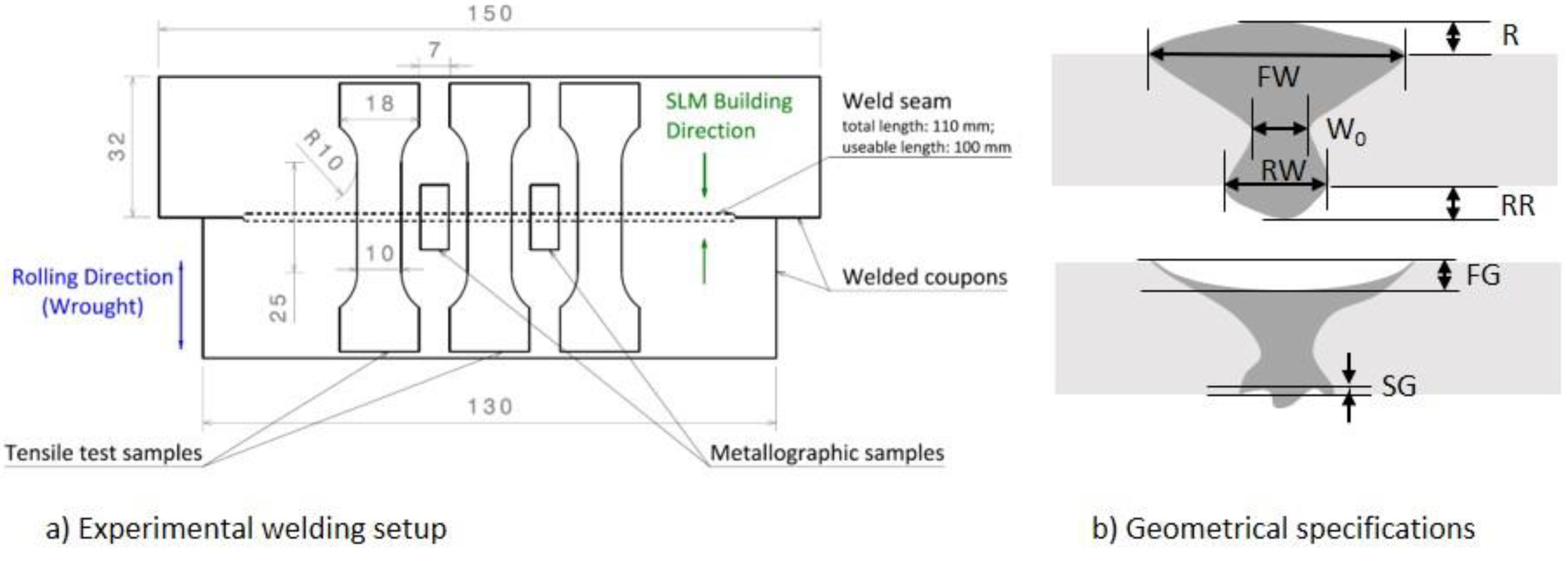
2.2. Laser Welding
2.3. Microstructural Characterization
2.4. Mechanical Characterization
3. Results
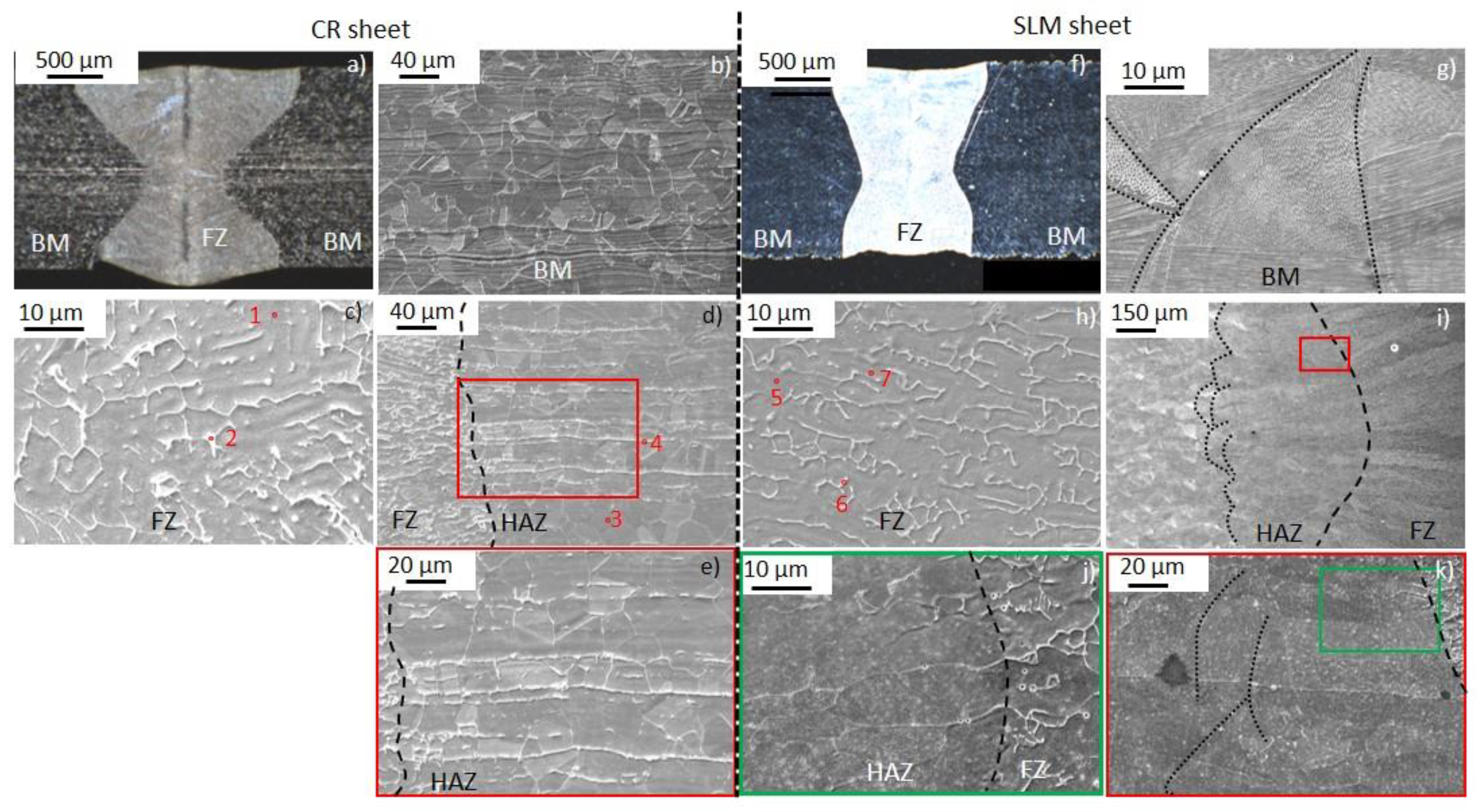
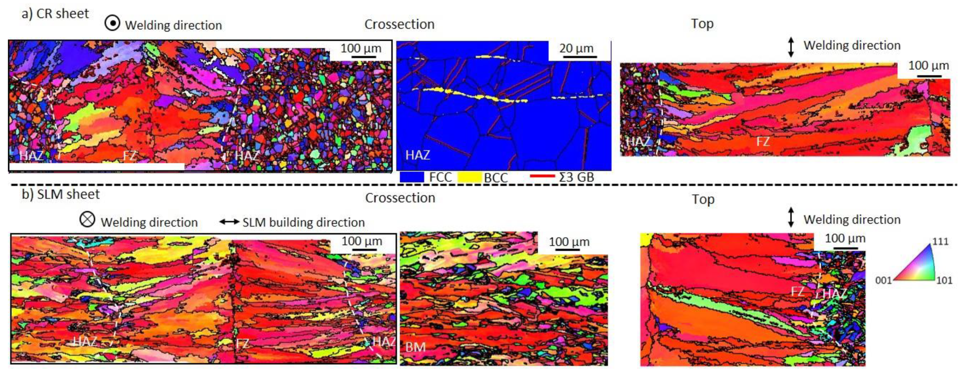
3.1. Microstructure
3.2. Mechanical Properties
4. Discussion
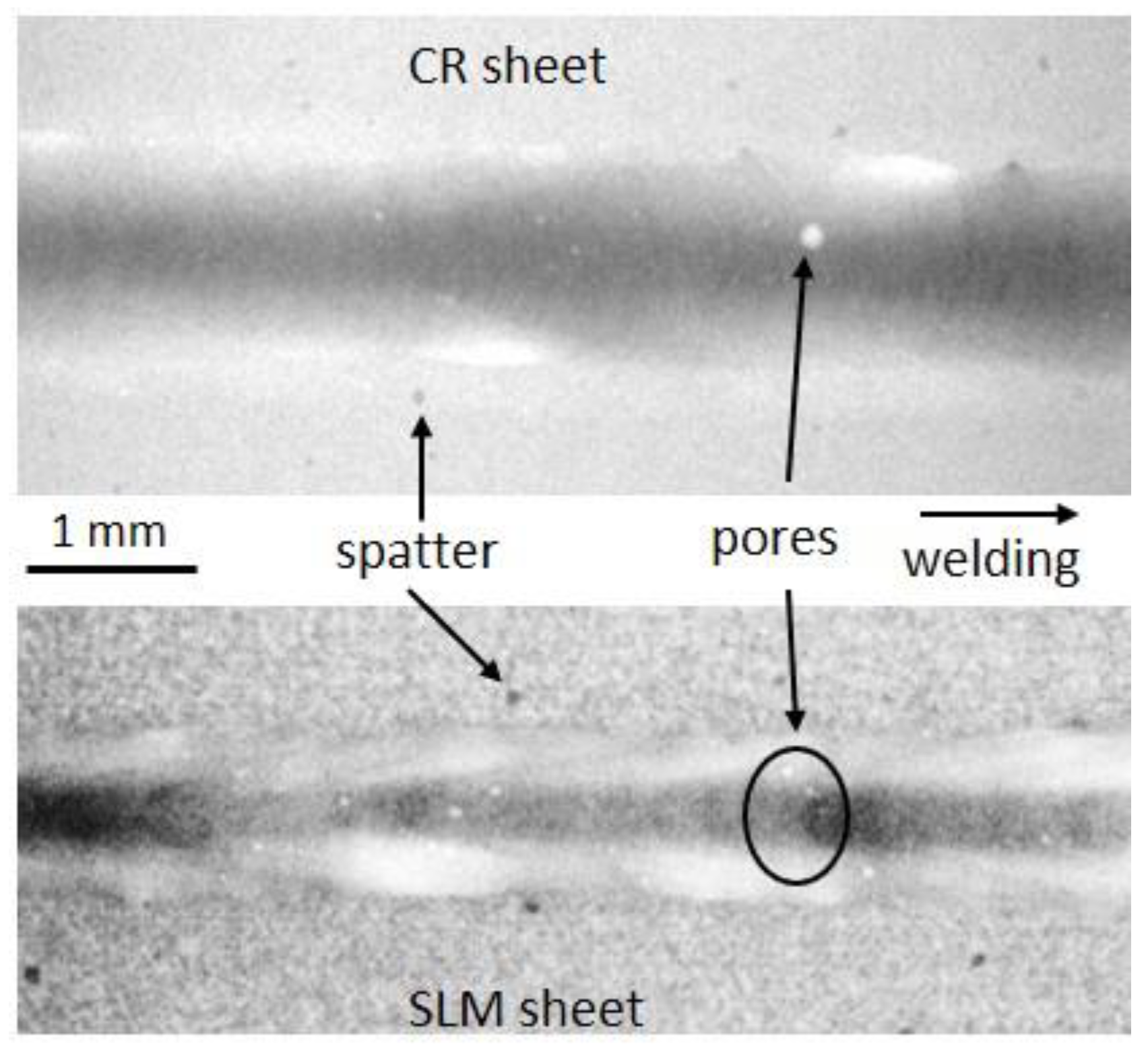
4.1. Material Health
4.2. Fuzion Zone Geometry and Microstructure
4.3. Relation Microstructure-Properties
5. Conclusions
- Both welds were defect-free and had X-shape geometry. However, the SLM weld seam showed a different geometry with no reinforcement and had an almost constant width throughout the thickness and a lower melting efficiency;
- The composition led to a ferritic–austenitic mode of solidification, resulting in a ferritic skeleton at room temperature. Both fusion zones showed a ferrite content around 8%, which is consistent with the Schaeffler diagram.
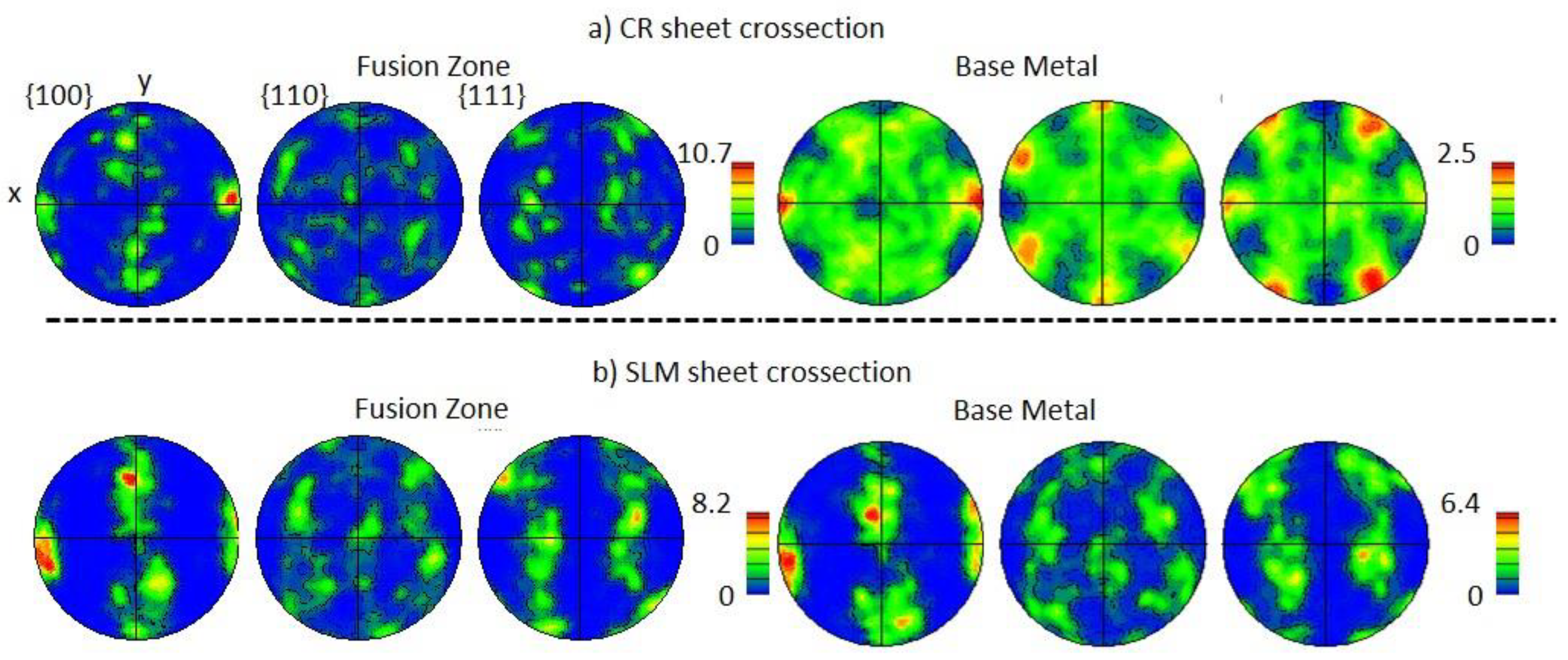
- Both texture (<100> in the solidification direction) and grain characteristics (anisotropic dendritic grains elongated in the solidification direction) of the fusion zone were similar, irrespective of the base metal microstructure. However, an epitaxial growth was observed in both the SLM base metal and fusion zone, while the fusion zone of the CR sheet resulted from grain growth with a privileged orientation from austenitic twined equiaxed grains.
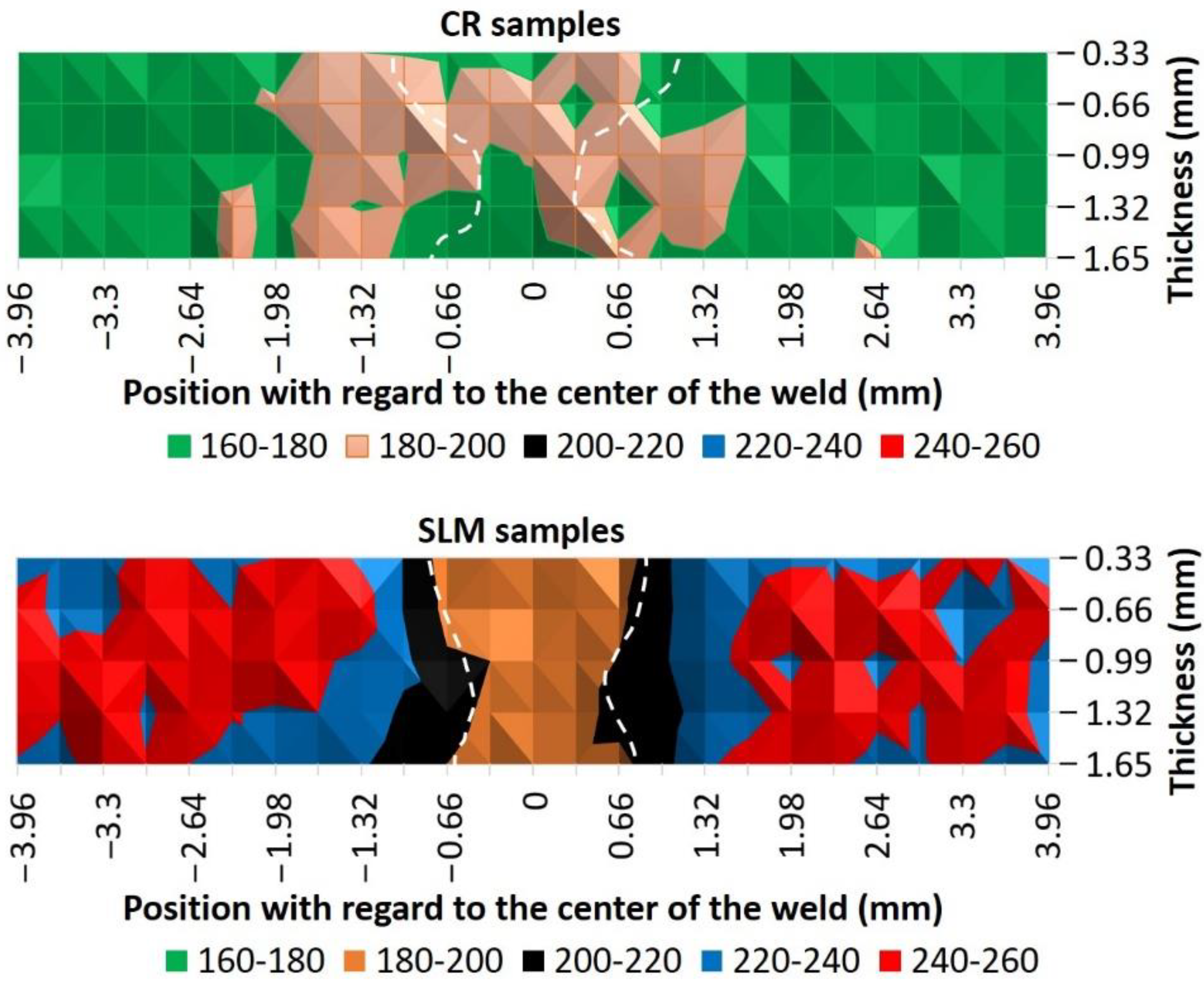
- Hardness variation was clearly observed in the SLM heat-affected zone and fusion zone compared to base metal, but this variation was less significant in the CR samples. Both fusion zones presented a similar hardness, which is consistent with similar welding parameters and dendrite thickness in the fusion zone.
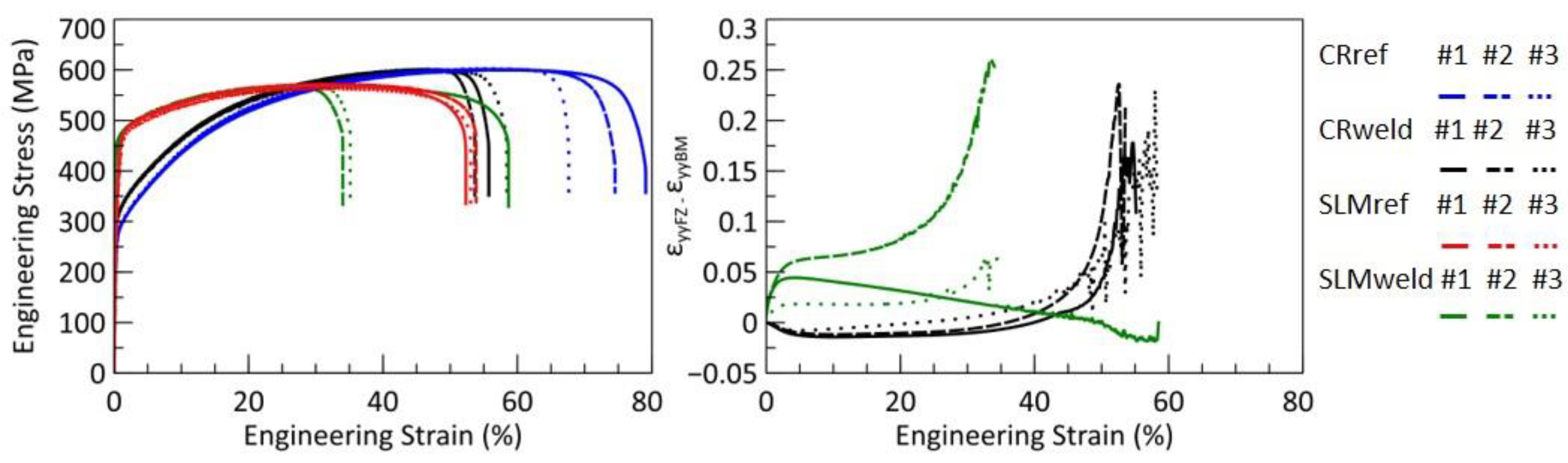
- Fracture occurred in the fusion zone for all samples. Welding had a low impact on the elastic and hardening behavior; however, necking behavior was modified. Although a decrease in ductility of around 30% compared to the base metal was observed, the welded samples from SLM plates still presented a ductile behavior with an elongation at break of around 40%.
- Even if failure occurred in the fusion zone in both configurations, the straining sequences were different. Regarding the SLM weld samples, strain developed preferentially in the fusion zone where the final fracture occurred. This is consistent with the lower hardness and the larger dendrite thickness in the fusion zone compared to the base metal. A different behavior was observed for the CR weld samples: strain initially developed in the base metal and then became preponderant in the fusion zone. The heterogenous microstructure of the fusion zone could favor damaging and, as a consequence, correspond to the failure zone.
Author Contributions
Funding
Data Availability Statement
Acknowledgments
Conflicts of Interest
References
- Huang, X.; Xiao, K.; Fang, X.; Xiong, Z.; Wei, L.; Zhu, P.; Li, X. Oxidation Behavior of 316L Austenitic Stainless Steel in High Temperature Air with Long-Term Exposure. Mater. Res. Express 2020, 7, 066517. [Google Scholar] [CrossRef]
- El-Batahgy, A.-M. Effect of Laser Welding Parameters on Fusion Zone Shape and Solidification Structure of Austenitic Stainless Steels. Mater. Lett. 1997, 32, 155–163. [Google Scholar] [CrossRef]
- Yamada, H.; Kawamura, H.; Tsuchiya, K.; Kalinin, G.; Kohno, W.; Morishima, Y. Re-Weldability Tests of Irradiated 316L(N) Stainless Steel Using Laser Welding Technique. J. Nucl. Mater. 2002, 307, 1584–1589. [Google Scholar] [CrossRef]
- Samanta, S.K.; Mitra, S.K.; Pal, T.K. Influence of Welding Speed on Microstructure and Oxidation Behaviour of Laser Welded Austenitic Stainless Steels. ISIJ Int. 2006, 46, 100–105. [Google Scholar] [CrossRef][Green Version]
- Yilbas, B.S.; Akhtar, S. Laser Welding of AISI 316 Steel: Microstructural and Stress Analysis. J. Manuf. Sci. Eng. 2013, 135, 031018. [Google Scholar] [CrossRef]
- Dontu, O.; Moreno, J.L.O.; Ciobanu, R.; Branzei, M.; Besnea, D. Study on Laser Welding of AISI 316L Austenitic Stainless Steel. J. Optoelectron. Adv. Mater. 2015, 17, 1444–1449. [Google Scholar]
- DebRoy, T.; Wei, H.L.; Zuback, J.S.; Mukherjee, T.; Elmer, J.W.; Milewski, J.O.; Beese, A.M.; Wilson-Heid, A.; De, A.; Zhang, W. Additive Manufacturing of Metallic Components—Process, Structure and Properties. Prog. Mater. Sci. 2018, 92, 112–224. [Google Scholar] [CrossRef]
- Liverani, E.; Toschi, S.; Ceschini, L.; Fortunato, A. Effect of Selective Laser Melting (SLM) Process Parameters on Microstructure and Mechanical Properties of 316L Austenitic Stainless Steel. J. Mater. Process. Technol. 2017, 249, 255–263. [Google Scholar] [CrossRef]
- Ahmadi, A.; Mirzaeifar, R.; Moghaddam, N.S.; Turabi, A.S.; Karaca, H.E.; Elahinia, M. Effect of Manufacturing Parameters on Mechanical Properties of 316L Stainless Steel Parts Fabricated by Selective Laser Melting: A Computational Framework. Mater. Des. 2016, 112, 328–338. [Google Scholar] [CrossRef]
- Tucho, W.M.; Lysne, V.H.; Austbø, H.; Sjolyst-Kverneland, A.; Hansen, V. Investigation of Effects of Process Parameters on Microstructure and Hardness of SLM Manufactured SS316L. J. Alloy. Compd. 2018, 740, 910–925. [Google Scholar] [CrossRef]
- Gu, D.; Shen, Y. Processing Conditions and Microstructural Features of Porous 316L Stainless Steel Components by DMLS. Appl. Surf. Sci. 2008, 255, 1880–1887. [Google Scholar] [CrossRef]
- Jokisch, T.; Marko, A.; Gook, S.; Üstündag, Ö.; Gumenyuk, A.; Rethmeier, M. Laser Welding of SLM-Manufactured Tubes Made of IN625 and IN718. Materials 2019, 12, 2967. [Google Scholar] [CrossRef]
- Faye, A.; Balcaen, Y.; Lacroix, L.; Alexis, J. Effects of Welding Parameters on the Microstructure and Mechanical Properties of the AA6061 Aluminium Alloy Joined by a Yb: YAG Laser Beam. J. Adv. Join. Process. 2021, 3, 100047. [Google Scholar] [CrossRef]
- Matilainen, V.-P.; Pekkarinen, J.; Salminen, A. Weldability of Additive Manufactured Stainless Steel. Phys. Procedia 2016, 83, 808–817. [Google Scholar] [CrossRef]
- Akbari, M.; Kovacevic, R. Joining of Elements Fabricated by a Robotized Laser/Wire Directed Energy Deposition Process by Using an Autogenous Laser Welding. Int. J. Adv. Manuf. Technol. 2019, 100, 2971–2980. [Google Scholar] [CrossRef]
- Kuryntsev, S.V. The Influence of Pre-Heat Treatment on Laser Welding of T-Joints of Workpieces Made of Selective Laser Melting Steel and Cold Rolled Stainless Steel. Opt. Laser Technol. 2018, 107, 59–66. [Google Scholar] [CrossRef]
- Mohyla, P.; Hajnys, J.; Sternadelová, K.; Krejčí, L.; Pagáč, M.; Konečná, K.; Krpec, P. Analysis of Welded Joint Properties on an AISI316L Stainless Steel Tube Manufactured by SLM Technology. Materials 2020, 13, 4362. [Google Scholar] [CrossRef]
- Yang, J.; Wang, Y.; Li, F.; Huang, W.; Jing, G.; Wang, Z.; Zeng, X. Weldability, Microstructure and Mechanical Properties of Laser-Welded Selective Laser Melted 304 Stainless Steel Joints. J. Mater. Sci. Technol. 2019, 35, 1817–1824. [Google Scholar] [CrossRef]
- Luo, C.; Lai, Z.; Zhang, Y. Improvement of Mechanical Properties of Dissimilar Spot-Welded Joints of Additively Manufactured Stainless Steels. J. Manuf. Process. 2020, 54, 210–220. [Google Scholar] [CrossRef]
- Casalino, G.; Campanelli, S.L.; Ludovico, A.D. Laser-Arc Hybrid Welding of Wrought to Selective Laser Molten Stainless Steel. Int. J. Adv. Manuf. Technol. 2013, 68, 209–216. [Google Scholar] [CrossRef]
- Huysmans, S.; Peeters, E.; De Bruycker, E.; De Prins, K. Weldability Study of Additive Manufactured 316L Austenitic Stainless Steel Components—Welding of AM with Conventional 316L Components. Weld World 2021. [Google Scholar] [CrossRef]
- Madeja, M.; Karoluk, M.; Smolina, I. Welding of Ti-5Al-5Mo-5 V-1Cr-1Fe Parts Manufactured in the Electron Beam Melting. Mater. Des. 2020, 195, 108969. [Google Scholar] [CrossRef]
- Sun, Y.Y.; Wang, P.; Lu, S.L.; Li, L.Q.; Nai, M.L.S.; Wei, J. Laser Welding of Electron Beam Melted Ti-6Al-4V to Wrought Ti-6Al-4V: Effect of Welding Angle on Microstructure and Mechanical Properties. J. Alloys Compd. 2019, 782, 967–972. [Google Scholar] [CrossRef]
- Wits, W.W.; Becker, J.M.J. Laser Beam Welding of Titanium Additive Manufactured Parts. Procedia CIRP 2015, 28, 70–75. [Google Scholar] [CrossRef]
- Sankar, G.S.; Karthik, G.M.; Mohammad, A.; Kumar, R.; Janaki Ram, G.D. Friction Welding of Electron Beam Melted γ-TiAl Alloy Ti–48Al–2Cr–2Nb. Trans. Indian Inst. Met. 2019, 72, 35–46. [Google Scholar] [CrossRef]
- Xu, M.; Chen, Y.; Zhang, T.; Deng, H.; Ji, D. Effects of Solution Treatment on Laser Welding of Ti–6Al–4V Alloy Plate Produced through Wire Arc Additive Manufacturing. Metals 2020, 10, 1310. [Google Scholar] [CrossRef]
- Chen, X.; Zhang, J.; Chen, X.; Cheng, X.; Huang, Z. Electron Beam Welding of Laser Additive Manufacturing Ti–6.5Al–3.5Mo–1.5Zr–0.3Si Titanium Alloy Thick Plate. Vacuum 2018, 151, 116–121. [Google Scholar] [CrossRef]
- Moeini, G.; Sajadifar, S.V.; Wegener, T.; Brenne, F.; Niendorf, T.; Böhm, S. On the Low-Cycle Fatigue Behavior of Friction Stir Welded Al–Si12 Parts Produced by Selective Laser Melting. Mater. Sci. Eng. A 2019, 764, 138189. [Google Scholar] [CrossRef]
- Du, Z.; Tan, M.J.; Chen, H.; Bi, G.; Chua, C.K. Joining of 3D-Printed AlSi10Mg by Friction Stir Welding. Weld World 2018, 62, 675–682. [Google Scholar] [CrossRef]
- Nahmany, M.; Hadad, Y.; Aghion, E.; Stern, A.; Frage, N. Microstructural Assessment and Mechanical Properties of Electron Beam Welding of AlSi10Mg Specimens Fabricated by Selective Laser Melting. J. Mater. Process. Technol. 2019, 270, 228–240. [Google Scholar] [CrossRef]
- Zhang, Y.; Hu, X.; Jiang, Y. Study on the Microstructure and Fatigue Behavior of a Laser-Welded Ni-Based Alloy Manufactured by Selective Laser Melting Method. J. Mater. Eng. Perform. 2020, 29, 2957–2968. [Google Scholar] [CrossRef]
- Rautio, T.; Jalava-Kanervio, J.; Kumpula, J.; Mäkikangas, J.; Järvenpää, A. Microstructure and Mechanical Properties of Laser Butt Welded Laser Powder Bed Fusion Manufactured and Sheet Metal 316L Parts. Key Eng. Mater. 2020, 861, 9–14. [Google Scholar] [CrossRef]
- Ascari, A.; Fortunato, A.; Liverani, E.; Gamberoni, A.; Tomesani, L. New Possibilities in the Fabrication of Hybrid Components with Big Dimensions by Means of Selective Laser Melting (SLM). Phys. Procedia 2016, 83, 839–846. [Google Scholar] [CrossRef]
- Giganto, S.; Zapico, P.; Castro-Sastre, M.Á.; Martínez-Pellitero, S.; Leo, P.; Perulli, P. Influence of the Scanning Strategy Parameters upon the Quality of the SLM Parts. Procedia Manuf. 2019, 41, 698–705. [Google Scholar] [CrossRef]
- Schaeffler, A.L. Constitution Diagram for Stainless Steel Weld Metal. Met. Prog. 1949, 56, 680. [Google Scholar]
- Faye, A.; Balcaen, Y.; Lacroix, L.; Alexis, J. Autogenous Yb:YAG Laser Disk Welding Domain of AA6061-T4 Aluminium Alloy. Int. J. Eng. Res. Sci. 2020, 6, 1–8. [Google Scholar] [CrossRef]
- Salman, O.O.; Gammer, C.; Chaubey, A.K.; Eckert, J.; Scudino, S. Effect of Heat Treatment on Microstructure and Mechanical Properties of 316L Steel Synthesized by Selective Laser Melting. Mater. Sci. Eng. A 2019, 748, 205–212. [Google Scholar] [CrossRef]
- Ronneberg, T.; Davies, C.M.; Hooper, P.A. Revealing Relationships between Porosity, Microstructure and Mechanical Properties of Laser Powder Bed Fusion 316L Stainless Steel through Heat Treatment. Mater. Des. 2020, 189, 108481. [Google Scholar] [CrossRef]
- Goossens, F.; Cherif, M.; Cahuc, O. Study of Polishing AISI 316L with Structured Abrasive. Int. J. Mach. Mach. Mater. 2015, 17, 434–453. [Google Scholar]
- Habraken, L.; de Brouwer, J.-L. Centre de recherches métallurgiques (Liège, Belgique). In De Ferri Metallographia: Bases de la Métallographie, Français. I.; Presses Académiques Européennes: Bruxelles, Belgium, 1966. [Google Scholar]
- Järvinen, J.-P. Welding of Additively Manufactured Stainless Steel Parts: Comparative Study between Sheet Metal and selective Laser Melted Parts. Master’s Thesis, Lappeenranta University of Technology, Lappeenranta, Finland, 2014. [Google Scholar]
- Moteshakker, A.; Danaee, I. Microstructure and Corrosion Resistance of Dissimilar Weld-Joints between Duplex Stainless Steel 2205 and Austenitic Stainless Steel 316L. J. Mater. Sci. Technol. 2016, 32, 282–290. [Google Scholar] [CrossRef]
- Yan, F.; Xiong, W.; Faierson, E.; Olson, G.B. Characterization of Nano-Scale Oxides in Austenitic Stainless Steel Processed by Powder Bed Fusion. Sci. Mater. 2018, 155, 104–108. [Google Scholar] [CrossRef]
- Saeidi, K.; Gao, X.; Zhong, Y.; Shen, Z.J. Hardened Austenite Steel with Columnar Sub-Grain Structure Formed by Laser Melting. Mater. Sci. Eng. A 2015, 625, 221–229. [Google Scholar] [CrossRef]
- Lou, X.; Andresen, P.L.; Rebak, R.B. Oxide Inclusions in Laser Additive Manufactured Stainless Steel and Their Effects on Impact Toughness and Stress Corrosion Cracking Behavior. J. Nucl. Mater. 2018, 499, 182–190. [Google Scholar] [CrossRef]
- Huang, Y.M.; Wu, Y.M.; Pan, C.X. EBSD Study of Solidification Characteristics of Austenitic Stainless Steel Weld Pool. Mater. Sci. Technol. 2010, 26, 750–753. [Google Scholar] [CrossRef]
- Kell, J.; Tyrer, J.R.; Higginson, R.L.; Thomson, R.C. Microstructural Characterization of Autogenous Laser Welds on 316L Stainless Steel Using EBSD and EDS. J. Microsc. 2005, 217, 167–173. [Google Scholar] [CrossRef]
- Pravin, K.M.; Varahamoorthi, R.; Gnanamurugan, K. Farvesh Modelling and Optimization of Process Parameters to Obtain Maximum Tensile Strength for Laser Butt Welding of 316L Austenitic Stainless Steel Sheets. Mater. Today Proc. 2020, 26, 1380–1388. [Google Scholar] [CrossRef]
- Kumar, N.; Mukherjee, M.; Bandyopadhyay, A. Comparative Study of Pulsed Nd:YAG Laser Welding of AISI 304 and AISI 316 Stainless Steels. Opt. Laser Technol. 2017, 88, 24–39. [Google Scholar] [CrossRef]
- Ragavendran, M.; Vasudevan, M. Laser and Hybrid Laser Welding of Type 316L(N) Austenitic Stainless Steel Plates. Mater. Manuf. Process. 2020, 35, 922–934. [Google Scholar] [CrossRef]
- Graneix, J.; Beguin, J.D.; Alexis, J.; Masri, T. Weldability of Superalloys Hastelloy X by Yb: YAG Laser. Adv. Mater. Res. 2015, 1099, 61–70. [Google Scholar] [CrossRef]
- Rajasekhar, K.; Harendranath, C.S.; Raman, R.; Kulkarni, S.D. Microstructural Evolution during Solidification of Austenitic Stainless Steel Weld Metals: A Color Metallographic and Electron Microprobe Analysis Study. Mater. Charact. 1997, 38, 53–65. [Google Scholar] [CrossRef]


| Laser Power (W) | Laser Scanning Speed (mm/s) | Layer Thickness (μm) | Hatching Distance (μm) | Scanning Strategy |
|---|---|---|---|---|
| 215 | 1800 | 40 | 50 | Hexagonal path [34] |
| Fe | C | Si | Mn | P | S | Cr | Mo | Ni | N | Ni eq | Cr eq | |
|---|---|---|---|---|---|---|---|---|---|---|---|---|
| CR | 69.27 ± 0.06 | 0.025 ± 0.001 | 0.409 ± 0.002 | 1.104 ± 0.005 | 0.027 ± 0.001 | <0.005 | 16.14 ± 0.07 | 1.90 ± 0.01 | 10.3 ± 0.1 | 0.11 ± 0.01 | 11.6 | 18.7 |
| SLM | 68.44 ± 0.16 | 0.021 ± 0.001 | 0.66 ± 0.03 | 1.011 ± 0.006 | 0.023 ± 0.001 | <0.005 | 16.31 ± 0.15 | 2.196 ± 0.005 | 10.74 ± 0.03 | 0.17 ± 0.01 | 11.9 | 19.5 |
| Power (kW) | Welding Travel Speed (m·min−1) | Focal Diameter (μm) | Power Density (W·mm−2) | Energy Density (J·mm−2) | Argon Flux (L·min−1) |
|---|---|---|---|---|---|
| 1.5 | 1 | 120 | 1.33 × 10⁷ | 955 | 25 |
| Sample | Porosity (%) | Pore Number | Pore Max. Diameter (mm) | Pore Diameter (mm) |
|---|---|---|---|---|
| CR | 0.2 | 87 | 170 | 58 ± 24 |
| SLM | 0.3 | 111 | 100 | 57 ± 22 |
| Sample | CR Sheet | SLM Sheet |
|---|---|---|
| Face width (FW) | 2.26 | 1.56 |
| Root width (RW) | 1.8 | 1.29 |
| Minimum width (W0) | 0.73 | 0.89 |
| Reinforcement (R) | 0.05 | NA |
| Face groove (FG) | NA | 0.09 |
| Root reinforcement (RR) | 0.2 | 0 |
| Shrinkage groove (SG) | 0.1 | 0.06 |
| W0/FW | 0.32 | 0.57 |
| RW/FW | 0.8 | 0.83 |
| Area (mm2) | 3.2 | 2.35 |
| Mass % | Fe | Cr | Ni | Mo | Mn | Si | O | S | P |
|---|---|---|---|---|---|---|---|---|---|
| 1 CR FZ dendrites | 69.46 | 17.13 | 10.28 | 1.31 | 0.65 | 0.40 | 0.50 | 0.23 | 0.03 |
| 2 CR FZ inter-dendritic | 64.02 | 22.13 | 6.02 | 2.77 | 0.48 | 0.42 | 0.58 | 0.43 | 0.15 |
| 3 CR HAZ matrix | 64.49 | 17.49 | 11.00 | 1.89 | 1.11 | 0.34 | 0.56 | 0.09 | 0.00 |
| 4 CR HAZ lines | 64.7 | 24.19 | 5.34 | 3.26 | 0.64 | 0.48 | 0.64 | 0.6 | 0.15 |
| 5 SLM FZ dendrites | 65.92 | 17.44 | 12.59 | 2.09 | 0.55 | 0.76 | 0.41 | 0.19 | 0.04 |
| 6 SLM FZ inter-dendritic | 66.44 | 21.04 | 6.87 | 3.57 | 0.33 | 0.82 | 0.57 | 0.28 | 0.09 |
| 7 SLM FZ dark dots | 52.45 | 16.4 | 8.64 | 1.05 | 6.1 | 4.48 | 10.35 | 0.47 | 0.06 |
| Sample | CR Sheet Fusion Zone | SLM Sheet Fusion Zone | SLM Sheet Base Metal |
|---|---|---|---|
| Dendrite thickness (μm) | 3.5 ± 0.8 | 3.1 ± 0.8 | 0.5 ± 0.2 |
| Ferrite content | 8 ± 3 | 8 ± 3 | 9 ± 2 |
| Analysis Area (mm²) | Grain Area (µm²) | Grain Aspect Ratio | Grain Orientation Spread (°) | |
|---|---|---|---|---|
| CR sheet Base Metal | 0.40 | 400 ± 531 | 1.7 ± 0.7 | 14 ± 13 |
| CR sheet Fusion Zone cross-section | 0.27 | 1519 ± 4860 | 2.2 ± 1.0 | 2.3 ± 6.4 |
| CR sheet Fusion Zone Top | 0.47 | 4853 ± 600 | 2.0 ± 0.9 | 1.1 ± 3.7 |
| SLM sheet Base Metal | 0.46 | 466 ± 3136 | 3.4 ± 2.2 | 2.5 ± 4.5 |
| SLM sheet Fusion Zone cross-section | 0.38 | 1869 ± 4774 | 4.4 ± 3.6 | 2.3 ± 4.4 |
| SLM sheet Fusion Zone Top | 0.50 | 2623 ± 319 | 2.8 ± 1.8 | 2.5 ± 6.1 |
| CR Sheet | Welded CR Sheet | SLM Sheet | Welded SLM Sheet | |
|---|---|---|---|---|
| Hardness BM (HV1) | 164 ± 5 | 166 ± 6 | 241 ± 5 | 238 ± 6 |
| Hardness FZ (HV1) | NA | 190 ± 8 | NA | 197 ± 5 |
| Yield stress (MPa) | 261 ± 19 | Not Applicable | 423 ± 5 | Not Applicable |
| Ultimate Tensile Strength (Mpa) | 602 ± 2 | 598 ± 3 | 568 ± 5 | 568 ± 2 |
| Elongation at break (%) | 73 ± 6 | 56 ± 3 | 51 ± 1 | 42 ± 14 |
| Failure position | Base Metal | #1, #2, #3 Fusion Zone | Base Metal | #1 Base metal #2, #3 Fusion Zone |
Publisher’s Note: MDPI stays neutral with regard to jurisdictional claims in published maps and institutional affiliations. |
© 2021 by the authors. Licensee MDPI, Basel, Switzerland. This article is an open access article distributed under the terms and conditions of the Creative Commons Attribution (CC BY) license (https://creativecommons.org/licenses/by/4.0/).
Share and Cite
Mokhtari, M.; Pommier, P.; Balcaen, Y.; Alexis, J. Laser Welding of AISI 316L Stainless Steel Produced by Additive Manufacturing or by Conventional Processes. J. Manuf. Mater. Process. 2021, 5, 136. https://doi.org/10.3390/jmmp5040136
Mokhtari M, Pommier P, Balcaen Y, Alexis J. Laser Welding of AISI 316L Stainless Steel Produced by Additive Manufacturing or by Conventional Processes. Journal of Manufacturing and Materials Processing. 2021; 5(4):136. https://doi.org/10.3390/jmmp5040136
Chicago/Turabian StyleMokhtari, Morgane, Pierrick Pommier, Yannick Balcaen, and Joel Alexis. 2021. "Laser Welding of AISI 316L Stainless Steel Produced by Additive Manufacturing or by Conventional Processes" Journal of Manufacturing and Materials Processing 5, no. 4: 136. https://doi.org/10.3390/jmmp5040136
APA StyleMokhtari, M., Pommier, P., Balcaen, Y., & Alexis, J. (2021). Laser Welding of AISI 316L Stainless Steel Produced by Additive Manufacturing or by Conventional Processes. Journal of Manufacturing and Materials Processing, 5(4), 136. https://doi.org/10.3390/jmmp5040136