1. Introduction
Due to superior features like color dispersion [
1], super-hydrophobicity [
2] and corrosion inhibition [
3], the hierarchical surface is widely applied in optics, energy, electronics, etc. [
4]. There are many techniques reported to fabricate successfully the hierarchical surface, including laser writing [
5], chemical etching [
6], electrical discharge machining [
7], extremophile bacteria [
8] and mould pressing [
9]. However, due to their limitations like specified material and expensive costs, the diamond cutting with better accuracy and flexibility gets a lot of attention in the researches on fabricating hierarchical micro-nano-structured surfaces [
10].
The hierarchical surface is generally comprised of the primary surface and the secondary micro/nano structures. As for the primary surface, lots of developed diamond cutting technologies have been published, like the ultra-precision diamond turning [
11] and the fly cutting [
12]. Especially for the diamond cutting process with the FTS, the various complex primary surface can be fabricated efficiently [
13]. The developments of toolpath determination [
14] and error compensation [
15] also further improve the machining precision of the primary surface. On this basis, fly cutting has been able to fabricate the pyramid secondary structures via removing materials from different directions. The designed cross toolpaths form specific residual tool marks, namely the pyramid secondary structures, the topography of which can be adjusted by redesigning the toolpath spacing and the cutting direction [
16]. The rotary ultrasonic diamond cutting also has the capacity to fabricate the hierarchical surface. The single point diamond mounted the ultrasonic spindle can periodically enter and leave the machined primary surface, resulting in that the micro dimples are favorably formed on the primary surface [
17]. Even so, the above technologies still take a great deal of time to determinate complicated toolpath, which must meet the requirements of fabricating the primary surface and the secondary structures at the same time. Obviously, one technique for fabricating the hierarchical surface with better flexibility and compatibility should be developed.
The vibration-assisted machining has conspicuous advantages in fabricating hierarchical micro-nano-structured surfaces. For most cutting technologies of fabricating the primary surface, exerting the assisted vibration can naturally induce periodic residual tool mark on the machined surface, namely the secondary structure. In addition, there are some reports revealing that the vibration-assisted machining can reduce the cutting force [
18] and increase the fatigue life of workpiece [
19]. For the ultra-precision diamond turning, the positions of the diamond tool and the workpiece can be interchanged to constitute the fly cutting. Via the application of assisted vibration, the corresponding toolpaths just focus on improving the machining accuracy of the primary surface, while nano dimples can be generated naturally [
20]. The assisted vibration also can be employed in the rotary ultrasonic diamond cutting. By means of the spindle generating high-frequency longitudinal vibration in the spindle axis, micro/nano sinusoidal textures can be formed on the inner surface of linear groove [
21]. Different from single assisted vibration, the micro milling combining orthogonal assisted vibrations has been developed to generate various micro/nano textures, which observably change the surface wettability [
22], via adjusting orthogonal vibration parameter. The elliptical vibration is one specific assisted vibration mode adding elliptical trajectories on the tooltip, which significantly reduces the chip thickness and has a great advantage in the optical surface fabrication of the brittle material. The core of elliptical vibration is the synergy between the machining and vibration parameters, which decides the secondary structure shape, like dimple arrays or step textures [
23,
24].
The collocations between machining and vibration parameters have significant impacts on the secondary structure shape. With the performance improvement of the vibration generator, various collocations can be achieved [
25]. Therefore, the modulated assisted vibration has the potential to fabricate various secondary structures [
26]. For instance, the ultra-precision diamond turning can be modulated into the process like milling for fabricating the micro/nano channels with different bottom surface [
27]. The micro/nano sculpturing with modulated elliptical vibration can form grooves with several waves [
28], and the variational secondary structures may bring functional differences for different areas of the primary surface [
29]. Obviously, the vibration modulation improves effectively matching attributes between the primary surface and the secondary structure. Whereas, for different diamond cutting technologies, the relationship between the secondary structures and the modulated assisted vibration still needs to be further studied and established.
Although a great number of methods have been developed to fabricate hierarchical micro-nano-structured surfaces, most of them cannot achieve one-step machining. The vibration assisted machining is a popular technique for fabricating synchronously the primary surface and secondary structures. However, the assisted vibrations are usually applied along cutting depth direction to generate random and imprecise secondary structure. In this paper, a dual-axial tool servo diamond turning method for ductile materials is proposed to develop the vibration-assisted machining through applying additional vibration along the direction that is perpendicular to the cutting depth direction. The
z-axis tool servo motion is used to fabricate the primary surface as the common diamond turning, and the
x-axis motion is added to generate the secondary structure and perform the tool setting error compensation. Via changing the
x-axis motion amplitude and period, the feature and size of the secondary structure can be controlled precisely. Thus the modulation of the machining parameter is also investigated to obtain desired secondary structure. More details are written below, and this paper is organized as follows: the basic principle of the proposed approach is explained in
Section 2. The toolpath determination including the error compensation and the interference detection is introduced in
Section 3. The numerical simulation results of the toolpath and demonstrating the effects of machining parameters on the secondary structure geometry are revealed in
Section 4. The proposed method is verified by a machining experiment for copper cylinders in
Section 5. Finally,
Section 6 concludes the paper.
2. Dual-Axial Tool Servo Diamond Turning Mechanisms
Figure 1a shows the basic principle for fabricating hierarchical micro/nano-structured surfaces via the proposed dual-axial tool servo diamond turning method. Based on common ultra-precision diamond turning, a FTS with at least
x- and
z-axis degrees of freedom is installed between the slide of ultra-precision lathe and the diamond tool to achieve better driving performance. The
z-axis degree of freedom is used to ensure that the tool edge is tangent to the machined primary surface like common diamond turning, and the
x-axis degree of freedom can provide the harmonic motion to control residual tool marks, namely the secondary structures.
In view of the fact that the FTS motion depends on the spindle rotation angle
c, the
x-axis tool servo motion can be preliminarily expressed as:
where
A is the motion amplitude, and
n is a coefficient determining the motion frequency. Note that the secondary structure generation is easily affected by various factors like spindle speed
s and feed per revolution
f, etc. As illustrated in
Figure 1b, only when the amplitude
A equal to
and coefficient
n achieving the phase difference
between adjacent toolpaths are performed, adjacent toolpaths can be tangent to each other, resulting in uniform fusiform secondary structures. In this case, assume that the used tool radius is
, the width
w and the height
h of single fusiform secondary structure can be calculated as:
Since the feed per revolution
f, the amplitude
A and the tool radius
are constant, the width
w and the height
h of secondary structure are invariable. As for the length
l of single secondary structure, it can be approximatively calculated as:
where
is the distance between the secondary structure and spindle centres. Obviously,
and
l decrease continuously in the ultra-precision turning, thus the cutting radius should depend on the design range of the structure length.
In addition to the above fusiform secondary structures, through using the amplitude
A far smaller than feed per revolution
f or zero phase difference between adjacent toolpaths, the proposed method also can fabricate micro/nano-channel or sinusoidal textures. On the contrary, if the amplitude
A is larger than
, there will be difform secondary structures synchronously formed on the primary surface. Thus, for forming desired secondary structures, the
x-axis motion should be modulated to adapt other machining parameters, and more detailed modulation method will be discussed in
Section 4.
3. Toolpath Determination for Dual-Axial Tool Servo Diamond Turning
Although different machining parameters may be applied in the turning process, the basic principles of the toolpath determination algorithm still are the same [
24,
27]. In addition, the toolpath generated in this paper is smooth, and the used motion frequency is far less than the elliptical vibration. Therefore, the dynamic effect is slight and ignorable. The universal toolpath determination, including a description of the diamond tool, determination of cutter location point (CLP), error compensation and interference detection, can be minutely explained in this section. To conveniently describe the relative locations and the geometries of the workpiece and the diamond tool, the workpiece coordinate system
-
and the tool coordinate system
-
are respectively established, as shown in
Figure 1.
In general, the workpiece and the diamond tool are described in the workpiece and tool coordinate systems, respectively. In the workpiece coordinate, the primary surface can be described as
. In the turning process, the workpiece also can be described in the cylindrical coordinate system, and the primary surface can be expressed as:
where
denotes the distance between primary surface point and spindle centres, and
is corresponding spindle rotating angle.
3.1. Cutter Location Point Determination
Assume that the nose radius and the rake angle of the diamond tool are respectively
and
, the used tool edge can be described in the spherical coordinate by:
where
and
are the lower and upper angle boundary of the cutting edge. To calculate the distance between tool edge and machined surface, the tool edge is uniformly discretized into
points. The
m-th point at the edge is
, and the corresponding tangent vector can be expressed as:
Since the spindle speed is constant in the turning process, the rotational angle of spindle also can be uniformly discretized into
points. In the cylindrical coordinate, the
l-th point in the
k-th revolution of spindle can be expressed as:
where
is the workpiece radius, and
f is the feed per revolution of lathe.
denotes the
x-axis tool servo motion, the determination of which will be detailedly explained in
Section 4. Via the rotation transformation, the
m-th tool edge point
can be described in the workpiece coordinate by:
where
The normal vector of the primary surface at the projection of the
m-th point at the edge can be expressed by:
Assume that the tool is located at the CLP, then the cutting edge should be tangential to the primary surface. Therefore, the tangent vector of the cutter contact point (CCP) should be perpendicular to the normal vector of its projection on the primary surface, and the CCP can be approximatively determined by:
On this basis, the determination of CLP can be regarded as calculating the minimum distance between tool edge discrete point
and corresponding profile on the primary surface which is projected along the
-axis. Therefore, the
l-th CLP in the
k-th revolution of spindle can be described as:
3.2. Tool Setting Error Compensation
Different from the ideal situation, there are often tool setting errors along the
x- and
y-axis directions in the actual machining process. As shown in
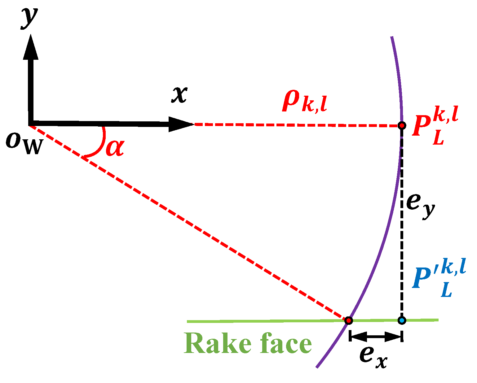
Figure 2, due to the angle discrepancy
, the tool setting error will lead to the distortion of micro/nano-structure. Thus, the error compensation is essential for obtaining a high-precision surface. By means of the ultra-precision lathe with the slow tool servo (STS), the
x-axis tool setting error can be readily eliminated. As for the
y-axis error, the
x-axis tool motion
needs to be tuned for countering the effect of angle discrepancy
.
Compared to the ideal situation, the compensated tool motion should be hysteretic, and the Equation (
1) can be written as:
with
where
is the tool setting error in
y-axis direction. Note that the angle discrepancy
indirectly causes the location error
in the
x-axis direction, and the location error
can be calculated as:
To counter the
x-axis location error
, Equation (
14) should be written as:
Substituting
to Equation (
8), the generated toolapth can avoid the surface topography error caused by the tool setting error.
3.3. Tool-Workpiece Interference Detection
The tool interference will result in overcut and tool damage. To obtain high-precision machined surface, the interference detection should be employed in the toolpath determination. When the tool move between adjacent CLPs, the
x- and
y-axial tool displacements can be approximatively expressed as:
In order to avoid the machining interference, the angle between the cutting velocity and the
y-axis should be less than the tool clearance angle. Therefore, the tool clearance angle
needs to meet:
When total CLPs meet Equation (
19), the generated toolpath can be applied in the actual machining.
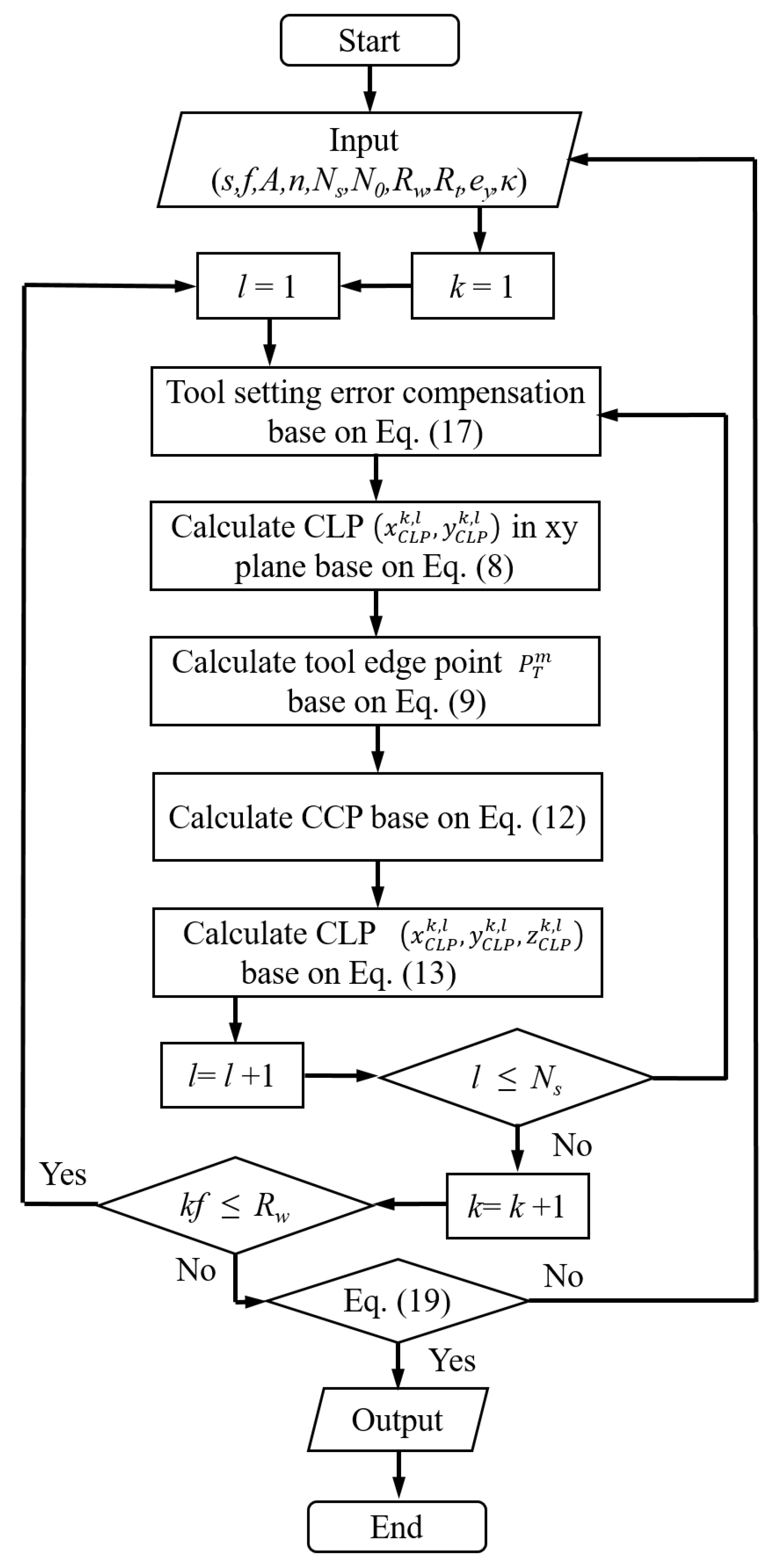
Based on the above discussion, the toolpath determination algorithm for the developed turning method can be indicated in
Figure 3. The tool setting error compensation is first carried out by delaying the
x-axis motion. Then the CLP coordinate can be respectively confirmed via calculating the minimum distance between tool edge discrete point and its corresponding profile on the primary surface. After obtaining all CLP coordinates, the interference detection is performed to ensure that there is no interference between the diamond tool and workpiece.
4. Numerical Simulation
Surface simulation is an effective way for predicting the surface topography and verifying the toolapth feasibility. Taking advantage of numerical count software, the desired toolpath and the machined surface can be simulated through the formulas derived in
Section 2 and
Section 3. To definitely demonstrate the effects of machining parameters on the secondary structures, the surfaces fabricated by three kinds of parameter combinations are simulated in this section. According to the discussion in
Section 2, the core of forming the secondary structure is controlling the toolpath spacing via amplitude and period of the
x-axis motion. Only when the amplitude of the
x-axis motion and the phase difference between adjacent toolpaths are, respectively
and
, the toolpaths are tangent. Considering the performances of lathe and self-designed FTS, the machining and
x-axis motion parameters listed in
Table 1 and
Table 2 were used in the simulation to generate different modes of toolpaths. In addition, the availability of error compensation in the toolpath determination is also verified via the comparison between non-compensated and compensated toolpaths.
4.1. Prediction of Toolpath and Surface Topography
As shown in
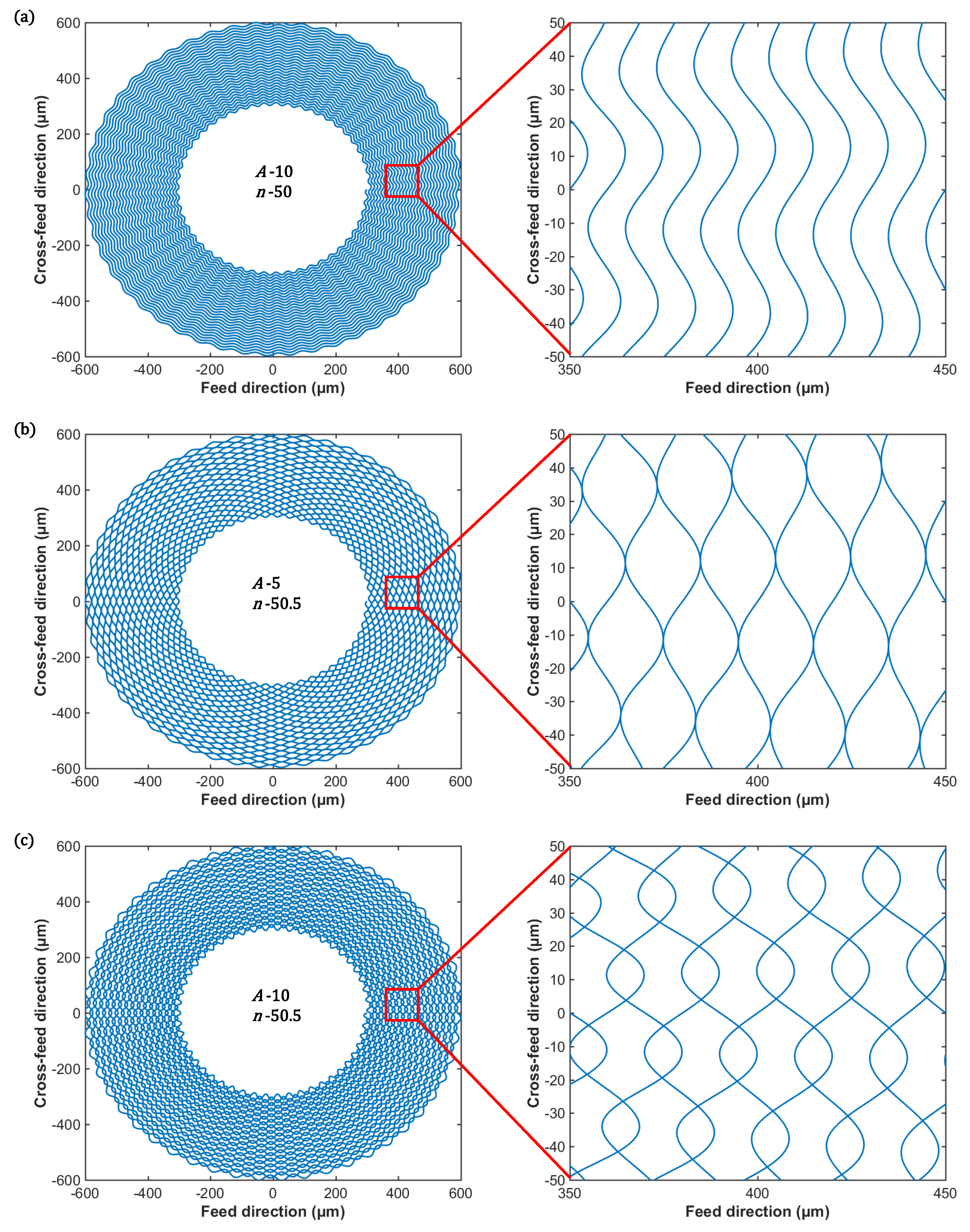
Figure 4, there are three modes of toolpaths generated by the method proposed in this paper, including non-contact-, contact- and cross-modes. As for the non-contact-mode toolpath shown in
Figure 4a, zero phase difference between adjacent toolpaths leads to the toolpath spacing identically equal to the value of
f, and the variation of amplitude
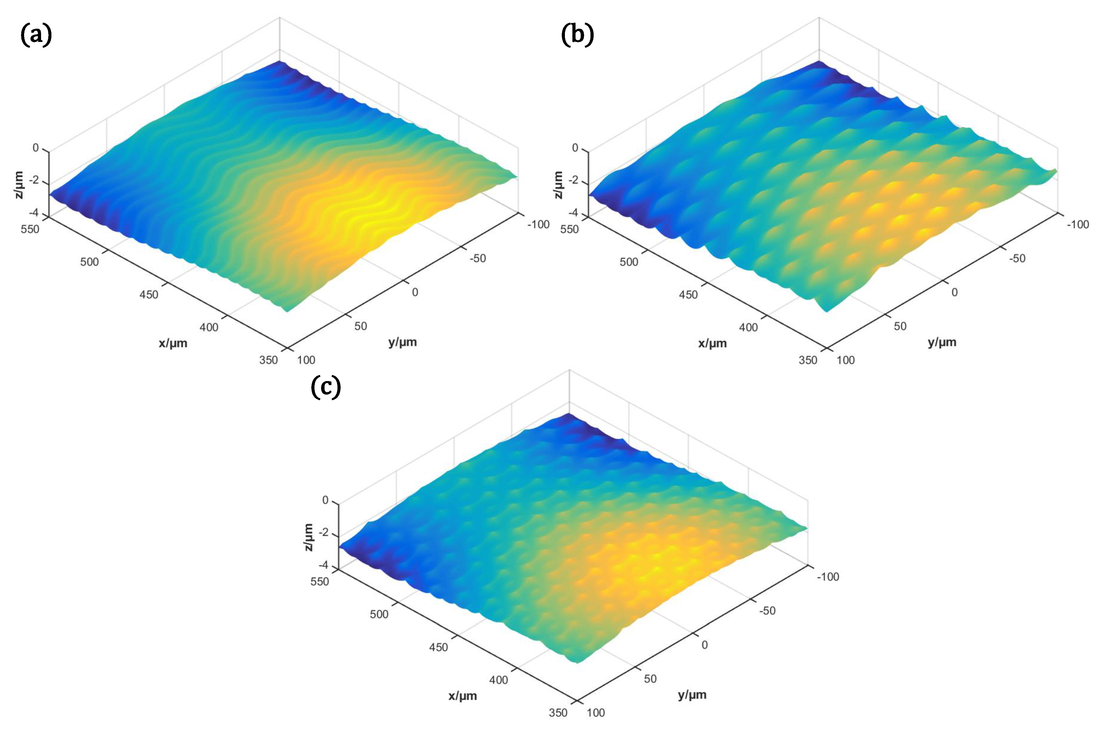
A cannot change the scallop height. Thus, the non contact-mode toolpath can be used in the fabrication of sinusoidal textures shown in
Figure 5a. If the feed per revolution
f is large enough to generate the desired scallop height, the non contact-mode toolpath also can fabricate micro/nano-channel. Assume that the phase difference between adjacent toolpaths is not zero, the amplitude
A smaller than
still can generate the non-contact-mode toolpath with varying spacing.
In
Figure 4b, the keys of generating the contact-mode toolpath are the phase difference
between adjacent toolpath and the amplitude
A exactly equal to
. Under this parameter combination, the width
w depends on the amplitude
A and the feed per revolution
f, while the length
l is decided together by the coefficient
n and the distance between the structure and spindle centers. If the amplitude
A is larger than
, the adjacent toolpaths will cross each other and generate the toolpath shown in
Figure 4c. Although the cross-mode toolpath also can fabricate the hierarchical surface like
Figure 5c, the formed secondary structures are non-uniform, and the structure geometry control is more complicated than the contact-mode toolpath. In contrast, the secondary structures fabricated by the contact-mode toolpath in
Figure 5b are more unified, the size of which can be controlled as the method described in
Section 2.
According to the above simulation results, to obtain the desired secondary structures mode, the x-axis tool servo motion should be modulated and adapt to the lathe motion. The phase difference of adjacent toolpaths decided by the coefficient n and the compatibility between the amplitude A and the feed per revolution f have a significant impact on the secondary structure mode. Besides, the lathe and FTS motions should be synchronized updated to achieve the desired secondary structure size. Otherwise, the secondary structures may change dramatically. For all the toolpath modes, the cutting radius decreases with the cutting time, resulting in the change of secondary structures size under constant machining parameter combination. Using a large cutting radius and small feed per revolution can minimize the variation of secondary structures size.
4.2. Prediction of Compensated Toolpath
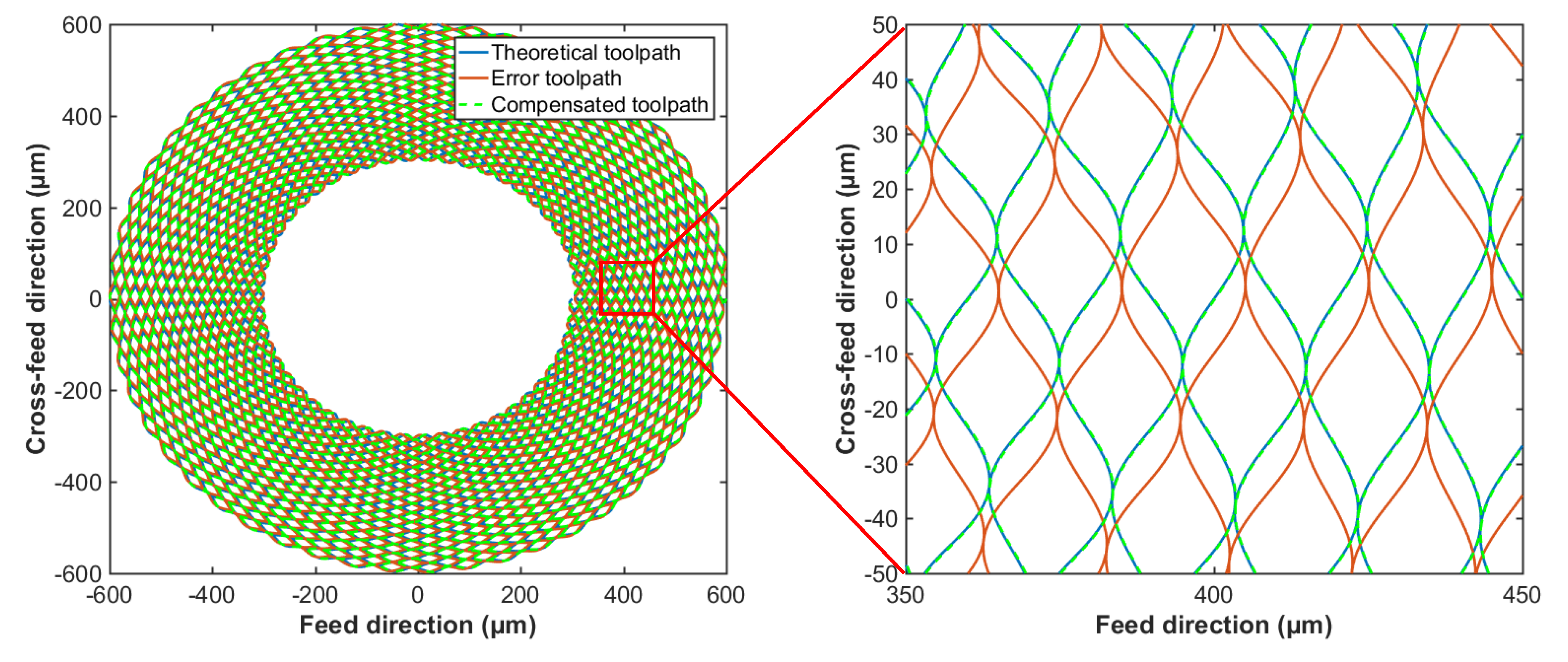
For the lathe without multi-axial FTS, the tool setting error is hardly avoided in the machining process. Thus, the error compensation should be employed in the toolpath determination. Assume that the tool setting error
is 10 μm, the non-compensated and compensated contact-mode toolpaths are shown in
Figure 6. Obviously, the tool setting error leads to the deviation of the theoretical toolpath, while the compensated toolpath can achieve better position accuracy. The deviation caused by the tool setting error
can be divided into two parts including the angle discrepancy
and the location error
. The angle discrepancy
is the leading cause resulting in the deviation, so the hysteretic
x-axis motion can effectively improve the position accuracy. Compared with the angle discrepancy
, the effect of location error
on the toolpath is tiny. Whereas, when the cutting radius decreases with the cutting time, the location error
increases significantly. For the fabrication of large-area hierarchical surface, the compensation of location error
should be interpolated into the tool motion to further improve the position accuracy.
5. Experiment Results and Discussion
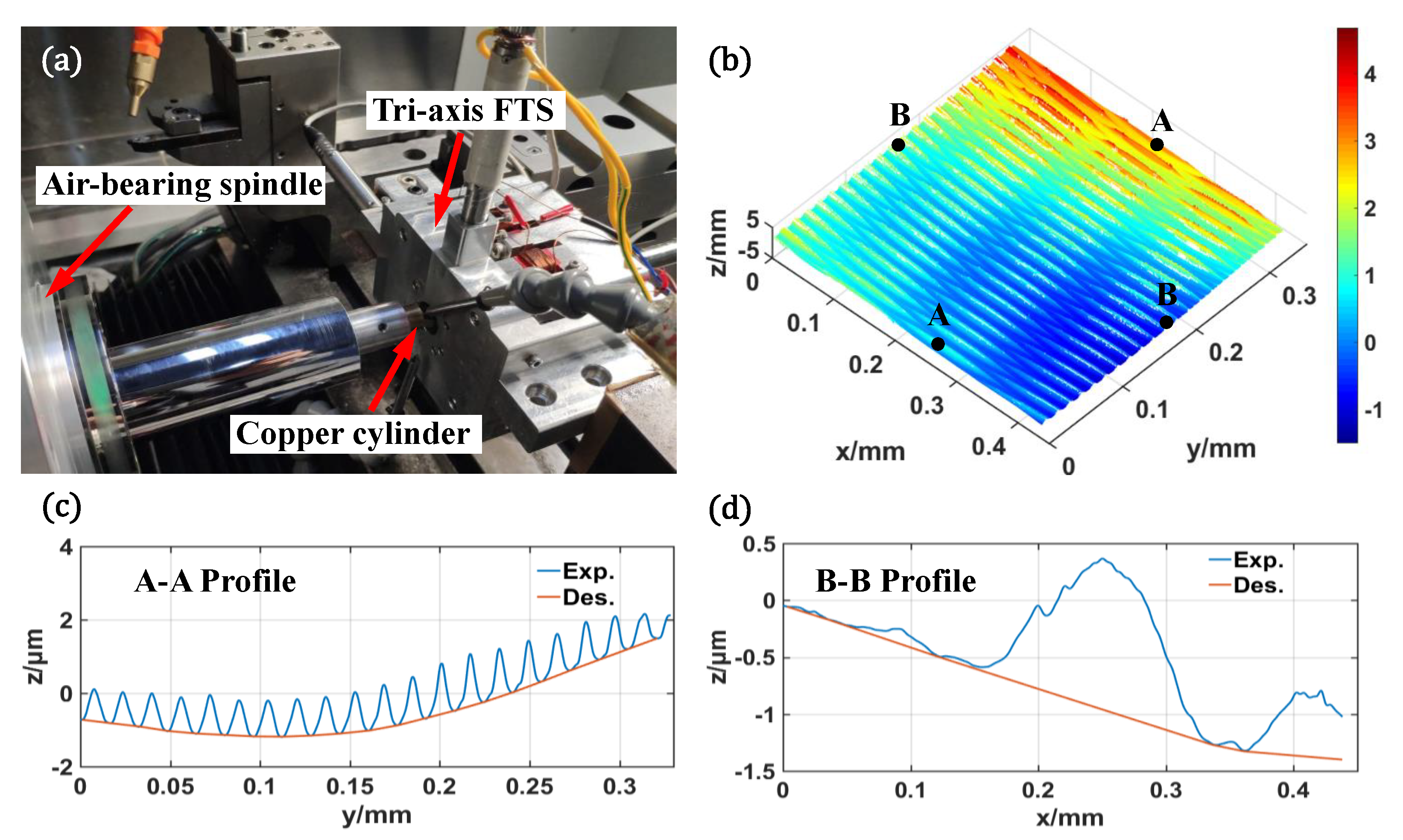
As shown in
Figure 7a, via a four-axis ultra-precision lathe (Moore Nanotech 350FG, USA) with self-designed tri-axial FTS [
30], one machining experiment was performed to verify the validity of the proposed method. The loopshaping tuned PID controller with a feedforward compensator and a damping controller are employed in FTS to improve the trajectory tracking accuracy. Through the closed-loop control, the planar and vertical following errors of FTS are about ±1.29% and ±1.23% for tracking harmonics with frequencies of 20 Hz and 50 Hz, respectively. Since the toolpaths similar to non-contact- and cross-modes have been reported in Ref. [
24], only the contact-mode toolpath was used in the experiment. According to
Section 4, the amplitude
A should be equal to
, and the phase difference between adjacent toolpaths should be
. Thus, the machining parameters listed in
Table 3 finally were employed in the experiment. Besides, as listed in
Table 4, the radius of used diamond tool is 20 μm, and the cylindrical copper part was clamped on the air-bearing spindle via the vacuum chuck.
After cutting, the part of the generated hierarchical surface shown in
Figure 7b were captured by the Optical Surface Profiler (Zygo Nexview). In
Figure 7c,d, the blue and red curves denote the profiles of machined surface and designed primary surface, respectively. According
Figure 7b,c, the fusiform secondary structures are successfully formed on the primary surface. Since the cutting radius is about 1 mm, the theoretical and formed structure sizes can be listed in
Table 5. Compared the theoretical values calculated as Equations (
2)–(
4), the errors of length, width and height respectively are 5.79%, 4.25% and 7.18%. There are many inevitable factors having the capacity to affect the experiment result, like material plastic deformation, FTS motion and measurement errors. The copper is softer material easily causing plastic deformation especially on the re-cutting area, resulting in that residual materials of structure ends are hardly captured. The noise also has significant impacts on the FTS accuracy. In addition, the primary surface used in the experiment is the sinusoidal surface, resulting in some measurement errors. Considering the above factors, there is actually a good agreement between the desired and experimental hierarchical surfaces. Therefore, the experiment results indicate that the method proposed in this paper is effective.

