Abstract
The increasing demand for high-performance components is leading to a greater use of advanced alloys such as DA718, which is, e.g., used in engine parts due to its high-temperature strength. The strict quality requirements pose major challenges for the machining of engine components for aircrafts. Quality deviations along the value chain can lead to high costs due to rework and, in the worst case, rejections in order to prevent material failure within a safety-critical environment. These deviations include, e.g., an increased surface roughness, deviations in the shape tolerances as well as increased internal stresses or surface deformations. Material defects are an additional reason to reject the manufactured components. These are usually inspected only at the end of the value chain and—due to measurement limitations—only if they occur close to the surface of the workpiece. Ultrasonic testing is used in order to detect defects near the surface of the raw part. For the evaluation of the finished part, etching and optical inspection of the surface is used. However, defects inside the components cannot be detected in this way. If material defects are located in areas subjected to intense load changes and high temperatures, the components have to be rejected since engine parts require a high level of fatigue strength. Such rejects constitute a significant economic risk, as a large part of the added value has already been completed and a significant amount of machine time has been invested. Thus, an identification of material defects in an earlier stage of the manufacturing process is required. In this paper, fundamental investigations on machining artificially generated material defects in a micro-milling process and the signal analysis during the pre-turning of turbine disks made of nickel-based materials like DA718 will be presented. Based on force measurements, characteristic signals were identified that could indicate material defects during the turning process.
1. Introduction
Increasing requirements for aircraft components regarding quality control, economic efficiency and supply pose huge challenges to the manufacturing industry. The demand to improve the performance of engine parts leads to an increasing complexity of the design of components that are accordingly more difficult to manufacture. Strict quality standards are specified for engine parts, including blades and blisks, which are exposed to intense thermal and alternating mechanical loads [1]. Such components are often made of titanium or nickel-based alloys. Melting or forging defects in the raw part can lead to crack formation over an uncertain period and component failures, which can even lead to a complete engine failure, as happened in the serious accident in Sioux City, Iowa 1989. In this case, a material defect led to an uncontained engine damage and crash of the airplane [1]. In this paper, a concept study for analyzing DA718 components for defects, such as clean and dirty white spots [2], during the manufacturing process based on in-process measurements is presented. Using the described approach, the presence of material defects within a machined part could be estimated early in the value chain, which enables the saving of valuable resources. Such estimations are based on the identification of material defects within the removed material as an input parameter for statistical models, which allowed estimations for the whole part.
Material defects are one reason to reject the manufactured components due to their effect on the mechanical properties and related increase of the failure probability [1,2]. These are usually inspected only at the end of the value chain and—due to measurement limitations—only if they occur close to the workpiece surface. For the detection of material defects such as cracks and blowholes, various detection methods are established. Typically, e.g., ultrasonic testing is used in order to detect defects close to the surface of the raw part [3,4]. For the evaluation of the finished part, etching and optical inspection of the surface are used [5,6]. However, defects deeper inside the components, such as white spots, cannot be detected this way and constitute a relevant risk for the manufacturing of aircraft engine components. If material defects are located in areas subjected to intense load changes and high temperatures, the components have to be rejected since engine parts require a high level of fatigue strength [7,8]. Such rejects constitute a significant economic risk, as a large part of the added value has already been completed, and a significant amount of machine time has been invested. Thus, an identification of material defects in an earlier stage of the manufacturing process is required.
Previous approaches for in-process monitoring based on acoustic emission (AE) sensors focused on an anomaly detection on the surface of the workpiece [9,10] and tool conditions [11,12] as a result of the process-specific load, or considered anomalies in the workpiece material under abstracted conditions such as the orthogonal cut [13]. Most investigations focused on continuous machining processes such as turning [14] and drilling [15], where deviations can be recognized more easily. Minor attention was paid to defects in the material including drags due to plastic deformation, redeposited material and plucks based on intense friction triggered by tool wear [16]. Recent approaches applied AE sensors and force measurement technologies in milling operations, e.g., for the classification of wood [17] or the quality control of CFRP components [18].
This paper focuses on turning of DA718, which is used for many thermally and mechanically loaded turbine components and relatively often subjected to material defects. Preliminary micro-milling experiments were conducted in order to consider scaling effects regarding the size ratio between the cutting tool and the material defect, and to estimate the potential of a transfer to milling processes. The selected process strategies are partly not representative for manufacturing aircraft components, but beneficial in terms of the fundamental studies. AE sensors and a force measuring platform were used to monitor and evaluate the manufacturing process. The presented approach aimed to detect defects in the workpiece material, which provide information about the quality of the forged raw part. This included fundamental investigations on machining defected material in a micro-milling process and the signal analysis during the pre-turning of turbine disks made of nickel-based materials like DA718 with artificially inserted material defects. Based on force and AE measurements, characteristic signals were identified that could indicate material defects during the turning process.
2. Materials and Methods
2.1. Preliminary Tests Using Micro-Milling
In order to evaluate the fundamental feasibility of an in-process identification of material defects in nickel-based alloy DA718, experimental investigations were conducted in analogy to previous investigations [19]. To benefit from scale effects, which cause a higher degree of influence of machining defected material on characteristic process conditions, a micro-milling process was designed. The experimental setup based on a micro-milling machining center Kern HSPC 2522 and included measurement systems for the determination of specific cutting force and AE signals (Figure 1A).

Figure 1.
Experimental setup including the measurement systems used and defected workpiece (A), and schematic representation of the process configuration (B) [19] (Reproduced from D Pfirrmann, J Baumann, E Krebs, D Biermann, K Morik. Real-time prediction of process forces in milling operations using synchronized data fusion of simulation and sensor data. Engineering Applications of Artificial Intelligence. 2021; 99: 165–170. Copyright © 2021 Elsevier Masson SAS. All rights reserved.
In contrast to force measurement systems, which have to be integrated in the kinematic path, e.g., between the workpiece and the machine table, a QASS AE sensor system can be attached to an existing component. The specimen included two areas which were effected by melting defects within the material. For specific investigations of the location and dimensions of the defected material volume, experiments were conducted in Section 1 (cf. Figure 1A). To determine the depth characteristics, Section 2 was machined. The tool used had a diameter of d = 1 mm and two cutting edges. Within the described experiments, down-milling was applied within a linear tool path using a cutting velocity of vc = 90 m/min, an axial depth of cut ap = 0.04 mm, a radial depth of cut ae = 0.4 mm and a feed per tooth fz = 0.05 mm (Figure 1B).
The cutting forces in x-, y- and z-direction were determined during the processes using a Kistler MicroDyn (Type 91009AA), whereas the feed velocity was oriented contrary to the x-direction. As depicted in Figure 2A the presence of a material defect had a significant impact on the process forces. The process forces decreased when a material defect in the nickel-based alloy DA718 was machined. The decrease of the cutting force components in the experiments presented occurred with a ratio up to approximately 45%, which was influenced by the decreased hardness properties within the material defect, as a result of the micro-structural change.
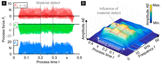
Figure 2.
Cutting forces (A) and acoustic emission (B) influenced by a material defect.
The measurement of process forces constitutes an indicative analysis technique, which is usually not feasible for industrial production processes, as the integration of additional compliant components such as a force measurement platform can result in instable process conditions. With regard to the transfer behavior, a positioning of an AE sensor as close as possible to the effective zone is preferable. As depicted in Figure 2B, the machining of a material defect caused an increase of the acoustic emission level, which corresponds to the increased deviation of emitted acoustic amplitudes.
The identification of a material defect based on the cutting forces was feasible. As the boundaries of the zone of influence were hardly detectable, the size of a defected section was difficult to determine. Besides the described process configuration, the parameter values were varied in order to identify appropriate process configurations and to evaluate the sensitivity of the material defect detection method with regard to the process design (Table 1).

Table 1.
Evaluated parameter values of the micro-milling process.
As indicated in preliminary investigations material defects in nickel-based alloy DA718 could be identified using cutting force measurements or evaluating the acoustic emissions. The identifiability was dependent on the process parameter configuration and the ratio between the dimensions of the material defect and the tool. A high chip thickness resulting from, e.g., high feed rates was beneficial. As only processes with unidirectional linear tool paths were investigated, the impact of the change of the engagement conditions, which is characteristic for most manufacturing processes, could be neglected. The effect of the time variant engagement conditions on the cutting forces and AE is superimposed with the impact of a material defect. As a result, the separation between engagement related and material related impacts on the measurement signals and, thus, the identification of material defects in real production processes is a much greater challenge [19].
2.2. Experimental Setup for Turning Experiments
The preliminary investigations indicated the potential of a material defect detection based on in-process measurements. Based on the intention to reduce the complexity of process conditions, a turning process was initially selected for further investigations. Compared to milling processes with, e.g., a characteristic permanent change of engagement conditions, the continuous cut allows to detect material-related changes during the turning operation more easily.
A WFL M65 MuliTurn was selected as a test machine, as its design is typical for a mill-turning center. A Kistler dynamometer Type 9129AA was used to measure the cutting forces and indicate material defects during the machining operation. In order to get close to the origin of the cutting forces, the dynamometer was mounted between two adapted Capto C6 interfaces and allowed a direct attachment of the tool holder and, therewith, an integration into the force flow (Figure 3).
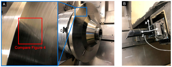
Figure 3.
Experimental setup for turning processes with the workpiece (A) and the tool setup for force measurement (B).
Since the flow of the coolant through the tool holder would be interrupted by components of the dynamometer, external cooling had to be used. The force data measured were synchronized with the position data of the main axis of the machine tool to ensure a local assignment of the force signal.
Specific process parameters were varied (Table 2), and the related effects on the process as well as the potential for the material defect detection were determined within basic tests. Feed rate and cutting speed were defined with regard to the parameter values used in series production. The depth of cut was varied to simulate both, rough turning and finishing processes. The depth of cut is relevant, as the depth of the defect is usually not known.
Table 2.
Evaluated parameter values of the turning experiments.
2.3. Preparation of the Workpieces
The mandatory application of extensive quality assurance methods in the production of aerospace components leads to a comparably rare occurrence of material defects in raw parts. The non-destructive detection of material defects is challenging and, thus, the location, shape and size of a material defect are usually unknown. To be able to investigate the effect of material defects on the machining process, specimens with statically induced defects were prepared. In order to ensure conditions as close as possible to the actually occurring defects, a raw part of the same nickel-based material DA718 was used. Various opportunities for the insertion of synthetic flaws were tested. These include spot heat treatment by induction and the shrinking of specially heat-treated rods into holes provided for this purpose. Metallographic analysis indicated that the best results were achieved with electron beam welding, as depicted in Table 3. In this process, a blind seam was placed on a blank (Figure 4). This had the advantage that the heat-affected zone created a smooth hardness transition between the base material and the defect. The depth of the seam was about ds = 24 mm and the width about ws = 2.5 mm at the thickest point on the surface. The affected area of the raw part was melted again and solidified naturally, without any special cooling process. The hardening that is normally carried out in the production of DA718 was lost in this way, causing a loss of approximately 50% of hardness compared to the base material. For first basic tests, investigations with this significant difference in hardness were carried out.
Table 3.
Characteristics of the material defects.
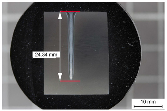
Figure 4.
Artificially induced material defect.
In order to achieve the specific properties of the DA718 material, the test parts were subjected to a direct-aged (DA) hardening process. This way, the so-called γ″-phase was formed within the material (Figure 5) which led to a significant increase in hardness [20,21]. After the hardening process, the artificial defect showed a reduction in hardness of approximately 10% in comparison to the base material (Table 3) and could therefore be evaluated as representative for the related material defects.

Figure 5.
Microscopic image of the micro-structure of the heat transition zone before (A) and after the hardening process (B).
3. Results and Discussion
In order to find the appropriate engagement conditions for the detection of artificial material defects, different process influences were varied and evaluated. Additionally, the measured force values were evaluated.
3.1. Evaluation of the Cutting Forces in Turning Processes
In addition to the process parameters such as cutting depth, cutting and feed velocity (Table 2), the cutting material (cemented carbide, ceramics) was also varied. Figure 6 depicts the signals measured with the dynamometer for the z-axis using both cutting materials. These signals should only be compared in a qualitative sense, as the specific tool geometries and cutting velocities differ. the comparison shows that the defect-specific signal characteristics occur in a comparable manner for a wide range of process variations.
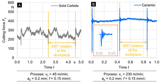
Figure 6.
Cutting force measured in z-direction using tools of cemented carbide (A) and ceramic (B).
Both force progressions indicate periodic transient variations which correspond to the recurring cuts into the material defect. It can be seen that the force signal is subjected to a significant transient decrease, followed by dynamically influenced homogenization. The decrease of process forces can be explained by the decreased local hardness when the cutting edge engaged the defect. Due to the reduced hardness of the material defect (Table 3), the depth of cut increased as a result of the reduced quasi-static deflection within the defect. Re-entering the base material, which exhibits a significantly higher hardness, led to an impulse-like excitation and dynamic deflections between the tool and workpiece.
The use of both cutting materials resulted in comparable characteristics when penetrating into the defected material zone, but the signal of the ceramic insert was subjected to a higher degree of dynamic effects on the force signal after re-entry into the base material. This behavior can result from the significantly higher level of the process forces and the resulting dynamic excitation. The conducted tests using ceramic inserts exhibit less fluctuating force signals. For this reason, ceramic tools and the corresponding cutting parameters were selected for further investigations.
3.2. Comparison of the Force Components in Turning Processes
In order to ensure a high degree of signal quality, the signals of all cutting force components were considered and examined. The machining of a material defect shows the known signal pattern in all force components, but in a various extend and with different specifications. While the defect-related increase of the amplitude in x-direction was approximately 70 N, the y-component exhibited a two, and the forces in z-direction exhibited an over five times higher increase. The y-component showed a significantly longer decay compared to the other axes. After comparing the signals of all three force components, it can be clearly seen that the z-component, which corresponds to the passive force, delivered the highest sensitivity on the occurrence of a material defect (Figure 7). For this reason, this component was considered in the following.
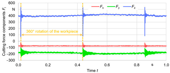
Figure 7.
Sensitivity of the cutting force components in x-, y- and z-direction on a material defect.
3.3. Sensitivity of the Cutting Depths in Turning Processes
In order to analyze the influence of the chip thickness on the signal quality, different cutting depths were analyzed. Figure 8 depicts the progression of the process force component in z-direction in dependency of the depth of cut ap. It can be seen that only the value of the amplitudes and the general level of the cutting force component increased, but there is no significant effect on the signal quality when increasing the cutting depth. The defect is clearly visible at all cutting depths. With regard to real melting defects with unknown location and size, the depth of cut is expected to be essential in terms of the identification of defects. If the cutting depth exceeds the size in depth of the material defect, the impact on the measurement signals is anticipated to occur attenuated.
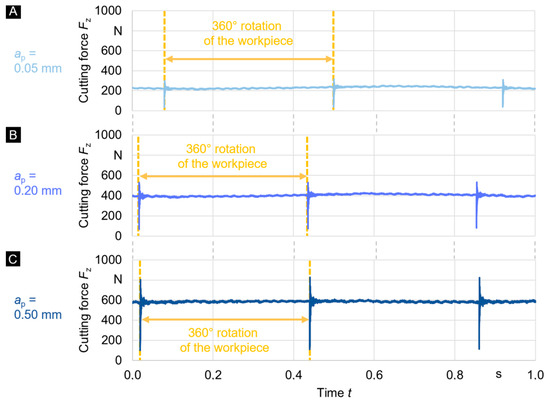
Figure 8.
Signals of the process force component at a depth of cut ap of 0.05 mm (A), 0.2 mm (B) and 0.5 mm (C).
3.4. The Effect of Post-Treatment on the Machining of Defected Material
In the following, the results of the post-treated, hardened defect are presented in the following. Figure 9 depicts the process force signal in z-direction. The signal fluctuation, which was identified to be characteristic for the investigated material defects in DA718, is clearly visible, but, as expected, in a weakened extend. However, the characteristic effects also occurred here regularly at the same rotational position and with a significant intensity.
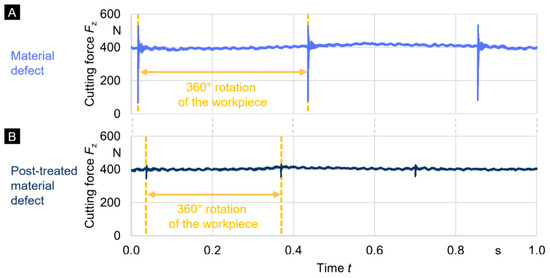
Figure 9.
Cutting force components in z-direction during the machining of a post-cured material defect.
4. Conclusions and Outlook
The experimental setup presented was introduced to evaluate an opportunity for the detection of internal material defects and to present first results of an application. Synthetic flaws in DA718 were produced, the prepared specimens were machined, and the artificial material defects were detected based on force measurements. With the chosen methodology, characteristic signal patterns indicating the occurrence of a material defect could be identified and described. These patterns were recognized by basic tests, validated with a measuring setup and a post-hardened part, which is more representative for real material defects.
The results allowed the detection of both unhardened and hardened artificial defects. The validation on serial components and in a real production environment is still pending. For this purpose, an experimental setup that is suitable to be applied in series-production processes is necessary. Since the dynamometer was directly integrated into the force flow in the conducted experiments (cf. Figure 3), internal cooling strategies could not be used. However, these strategies are necessary in order to ensure a process-safe series production. Otherwise, flow chips can occur, which can impair the quality of the surface of the component. In this context, the use of AE measurement techniques can be advantageous, as a system integration is much easier, and no inclusion into the force flow is necessary. Such analysis will be part of further investigations.
Author Contributions
Conceptualization, D.P., E.K., J.B., P.W. and D.B.; methodology, D.P., E.K. and J.B.; investigation, D.P. and E.K.; resources, D.P. and D.B.; writing—original draft preparation, D.P. and J.B.; writing—review and editing, D.P., J.B., P.W. and D.B. All authors have read and agreed to the published version of the manuscript.
Funding
This research received no external funding.
Institutional Review Board Statement
Not applicable.
Informed Consent Statement
Not applicable.
Data Availability Statement
Due to company-specific guidelines of one involved partner, the research data can generally not be made available. A possible provision must be evaluated on the basis of the individual request.
Conflicts of Interest
The authors declare no conflict of interest.
References
- National Transportation Safety Board. Aircraft Accident Report: United Airlines Flight 232, McDonnell Douglas DC-I0-10, Sioux Gateway, Airport Sioux City, Iowa; Report No. NTSB/AAR-90/06, Government Accession No. PB90-910406; National Transportation Safety Board: Washington, DC, USA, 1989.
- Thamboo, S.A. Melt Related Defects in Alloy 706 and Their Effects on Mechanical Properties; Materials Science—Superalloys; The Minerals, Metals & Materials Society: Pittsburgh, PA, USA, 1994; pp. 137–152. [Google Scholar]
- Chen, C.H. Ultrasonic and Advanced Methods for Nondestructive Testing and Material Characterization; World Scientific Publishing Co. Pte Ltd.: Singapore, 2007; pp. 349–369. [Google Scholar]
- Wagner, S.; Dugan, S. Ultrasonic inspection of Nickel alloys and Nickel alloy welds for high-temperature applications in modern Coal-fired power plants. In Proceedings of the 19th World conference on non-destructive testing, Munich, Germany, 13–17 June 2016. [Google Scholar]
- NASA. NASA Tech Briefs, 2nd ed.; NASA Scientific and Technical Information Facility: Hampton, VA, USA, 1990; Volume 3, p. 29.
- Crawford, G.I. Guide to Nondestructive Testing of Concrete; Publication No. FHWA-SA-97-105; U.S. Department of Transportation, Federal Highway Administration: Washington, DC, USA, 1997; pp. 30–31.
- Tavares, S.M.O.; De Castro, P. An overview of fatigue in aircraft structures. Fatigue Fract. Engin. Mater. Struct. 2017, 40, 1510–1529. [Google Scholar] [CrossRef]
- Niepokolczycki, A. Fatigue of Aircraft Structures; Institute of Aviation Scientific Publications: Warsaw, Poland, 2010. [Google Scholar]
- Axinte, D.A.; Gindy, N.; Fox, K.; Unanue, I. Process monitoring to assist the workpiece surface quality in machining. Int. J. Mach. Tools Manuf. 2004, 44, 1091–1108. [Google Scholar] [CrossRef]
- Beggan, C.; Woulfe, M.; Young, P.; Byrne, G. Using acoustic emission to predict surface quality. Int. J. Adv. Manuf. 1999, 15, 737–742. [Google Scholar] [CrossRef]
- Govekar, E.; Gradisek, J.; Grabec, I. Analysis of acoustic emission signals and monitoring of machining processes. Ultrasonics 2000, 38, 598–603. [Google Scholar] [CrossRef]
- Chiou, R.Y.; Liang S, Y. Analysis of acoustic emission in chatter vibration with tool wear effect in turning. Int. J. Mach. Tools Manuf. 2000, 40, 927–941. [Google Scholar] [CrossRef]
- Axinte, D.A.; Natarajan, D.R.; Gindy, N. An approach to use an array of three acoustic emission sensors to locate uneven events in machining—Part 1: Method and validation. Int. J. Mach. Tools Manuf. 2005, 45, 1605–1613. [Google Scholar] [CrossRef]
- Tönshoff, H.K.; Jung, M.; Männel, S.; Rietz, W. Using acoustic emission signals for monitoring of production processes. Ultrasonics 2000, 37, 681–686. [Google Scholar] [CrossRef]
- Kimmelmann, M.; Duntschewa, J.; Schluchtera, I.; Möhring, H.C. Analysis of burr formation mechanisms when drilling CFRP-aluminium stacks using acoustic emission. In Proceedings of the 19th Machining Innovations Conference for Aerospace Industry 2019 (MIC 2019), Garbsen, Germany, 27–28 November 2019. [Google Scholar]
- Marinescu, I.; Axinte, D.A. A critical analysis of effectiveness of acoustic emission signals to detect tool and workpiece malfunctions in milling operations. Int. J. Mach. Tools Manuf. 2008, 48, 1148–1160. [Google Scholar] [CrossRef]
- Eschelbacher, S.; Duntschew, J.; Möhring, H.C. Recognition of Wood and Wood-Based Materials During Machining Using Acoustic Emission; Production at the Leading Edge of Technology; Springer: Berlin/Heidelberg, Germany, 2019; pp. 317–325. [Google Scholar]
- Möhring, H.C.; Eschelbacher, S.; Kimmelmann, M. Material failure detection for intelligent process control in CFRP machining. Procedia CIRP 2018, 77, 387–390. [Google Scholar] [CrossRef]
- Pfirrmann, D.; Baumann, J.; Krebs, E.; Biermann, D.; Wiederkehr, P. Material defects detection based on in-process measurements in milling of Ti6246 alloy. Procedia CIRP 2021, 99, 165–170. [Google Scholar] [CrossRef]
- Renhof, L. Mikrostruktur und Mechanische Eigenschaften der Nickellegierung IN718. Ph.D. Dissertation, Technical University of Munich, Munich, Germany, October 2007. [Google Scholar]
- Schafrik, R.E.; Ward, D.D.; Groh, J.R. Application of Alloy 718 in GE Aircraft Engines: Past, Present and Next Five Years. Superalloys 718, 625, 706 and Various Derivatives; TMS (The Minerals, Metals and Materials Society): Warrendale, PA, USA, 2001. [Google Scholar]
Publisher’s Note: MDPI stays neutral with regard to jurisdictional claims in published maps and institutional affiliations. |
© 2021 by the authors. Licensee MDPI, Basel, Switzerland. This article is an open access article distributed under the terms and conditions of the Creative Commons Attribution (CC BY) license (https://creativecommons.org/licenses/by/4.0/).