Review

On the Fabrication of Metallic Single Crystal Turbine Blades with a Commentary on Repair via Additive Manufacturing

1
Department of Mechanical Engineering, The University of Alabama, Tuscaloosa, AL 35487, USA
2
Department of Mechanical Engineering, Pennsylvania State University, University Park, PA 16802, USA
*
Author to whom correspondence should be addressed.
J. Manuf. Mater. Process. 2020, 4(4), 101; https://doi.org/10.3390/jmmp4040101
Submission received: 27 July 2020 / Revised: 29 September 2020 / Accepted: 4 October 2020 / Published: 26 October 2020

Abstract

:
The turbine section of aircraft engines (both commercial and military) is an example of one of the most hostile environments as the components in this section typically operate at upwards of 1650 °C in the presence of corrosive and oxidative gases. The blades are at the heart of the turbine section as they extract energy from the hot gases to generate work. The turbine blades are typically fabricated using investment casting, and depending on the casting complexity, they generally display one of the three common microstructures (i.e., equiaxed or polycrystalline, directionally solidified, and single crystal). Single crystal casting is exotic as several steps of the casting process are traditionally hands-on. Due to the complex production process involving several prototyping iterations, the blade castings have a significant cost associated with them. For example, a set of 40 single crystal turbine blades costs above USD 600,000 and requires 60–90 weeks for production. Additionally, if the components suffer from material loss due to prolonged service or manufacturing defects, the traditional manufacturing methods cannot restore the parent metallurgy at the damage locations. Hence, there is a significant interest in developing additive manufacturing (AM) technologies that can repair the single crystal turbine blades. Despite the blades’ criticality in aircraft propulsion, there is currently no review article that summarizes the metallurgy, production process, failure mechanisms, and AM-based repair methods of the single crystal turbine blades. To address this existing gap, this review paper starts with a discussion on the composition of the single crystal superalloys, describes the traditional fabrication methods for the metallic single crystal turbine blades, estimates the material and energy loss when the blades are scrapped or reverted, and provides a summary of the AM technologies that are currently being investigated for their repair potential. In conclusion, based on the literature reviewed, this paper identifies new avenues for research and development approaches for advancing the fabrication and repair of single crystal turbine blades.

1. Introduction

Modern aircraft engines employ a Brayton cycle, which takes inlet air, compresses it, and then mixes it with fuel before expanding it through the turbine in order to generate the necessary thrust to propel the aircraft [1]. The turbine section of this cycle is responsible for extracting energy from the hot combustion gases. Recent developments in the design and production of the turbine components have led to a significant improvement in the cycle efficiency. The cycle efficiency (η) for a Brayton cycle is given by:
η = 1 T e T i
Here, Te is the exhaust temperature, and Ti is the inlet temperature. It is impossible for the exhaust temperature to be lower than the ambient temperature. Consequently, the design advancements focus on increasing the inlet temperature; however, such an increase directly correlates with an increase in the turbine operating temperature. Typically, an increase of 10 °C in the operating temperature increases the cycle efficiency by 1% [2]. In the past 30 years, the turbine operating temperature has increased from about 982 °C to about 1427 °C, posing a serious design challenge for the hot-section components. To deal with such high temperatures, three complementary approaches are adopted. First, to increase the blades’ resilience to oxidation and corrosion, thermal protection is provided to the components by coating them with metallic and ceramic materials. Second, elaborate and complex film cooling strategies (Figure 1) are implemented to keep the metal temperature within the design limits [3]. Third, high-creep strength and fatigue-resistant materials are employed to fabricate the turbine blades [4].
Nickel-base superalloys, that can operate closer to their melting temperatures without losing their structural integrity, are used to fabricate the turbine blades [4]. The blades are manufactured via investment casting where three different microstructures, specifically, equiaxed, directionally solidified, and single crystal (Figure 2), can be created [5]. Equiaxed (EQ) microstructures have multiple transverse grain boundaries with respect to the applied load. It is common for cavities to form at these grain boundaries. Consequently, EQ microstructures have an increased vulnerability to failures [6]. To address this issue, directionally solidified (DS) microstructures were developed. This type of microstructure contains an insignificant number of transverse grain boundaries as almost all the grains run along the loading direction. These parallel grain boundaries not only increase the creep and rupture strength of the components but also enhances the fatigue life of the components by giving it an advantageous modulus of elasticity with respect to the direction of loading [2,6]. A temperature benefit of approximately 23 °C (40 °F) in creep strength and an increase of approximately 10× in fatigue life were realized for DS GTD-111 compared to EQ GTD-111 [7].
In order to create turbine blades with even more superior creep strength and fracture resistance, a microstructure referred to as single crystal (SX), that does not contain any grain boundaries was developed [6]. This SX microstructure allows the removal of C (carbon) and B (boron) to a large extent, which decrease the melting temperature of an alloy as well as the fatigue strength. As an example, René N5, an SX-cast alloy, shows an increase of more than 35 °C (~60 °F) in creep strength and a 2–3 times improvement in fatigue life compared to DS GTD-111 [2]. SX microstructures can be further improved by adding Re (rhenium). The “first-generation” SX-cast superalloys (e.g., PWA 1480) do not contain Re and offer 25–50 °C improvement over rotor inlet temperature (RIT) and 1% improvement in creep life. The “second-generation” SX-cast superalloys (e.g., CMSX-4®) contain 3% Re and offer 30–35 °C improvement in RIT. The “third-generation” SX superalloys (e.g., CMSX-10®) contain more than 5 wt.% Re. This further enhances the creep-rupture strength and improves the RIT by 30 °C, enabling the use of un-cooled blades at 1200 °C, thus causing an increased efficiency by reducing the cold air requirement [7].
The SX turbine blades were originally developed by Pratt and Whitney in the 1960s and, since then, they have successfully been used to increase the service life [8]. However, because of material loss resulting from the abrasion between the blade tip and engine shroud, the SX turbine blades display a finite operating life despite their superior strength. Regulations dictate that once the blade tip loses a set amount of material, it may no longer be employed and must be repaired or scrapped. Additionally, fatigue cracks and other forms of damage (Figure 3b–d) [9]) at the shank, the dovetail, and the bottom of the airfoil limit the life of the turbine blades. Currently, when an SX turbine blade is damaged at the tip, it is typically repaired one to three times before being scrapped where it is either be reverted to regain its constituent materials or scrapped as waste (Based on our conversation with John Apostol, Principal Engineer—GEnx Program, American Airlines, Dallas, TX, USA). However, if there is damage at the shank or dovetail, or bottom of the airfoil, it cannot be repaired easily and needs to be scrapped. Once an SX blade is scrapped, a brand-new SX blade must be produced from scratch to replace it. This continuous cycle of producing new SX blades only to eventually scrap them and produce new replacement blades results in a large amount of material and energy waste as estimated in Section 5 of this article. With several hundred such components installed in each gas turbine engine, the total replacement cost at the time of overhaul for one engine can be upwards of hundreds of thousands or even millions of dollars per engine [2].
As the airline industry grows at an astounding rate, the material and the energy waste will only continue to increase if suitable measures are not found towards repairing the SX turbine blades. It is estimated that by the year 2027 the global fleet will have increased by approximately 10,000 aircrafts since 2017 [10]. Hence, there is a great interest in developing suitable repair techniques so that these SX turbine blades could be put back to service. With this objective, this paper reviews the investment cast production processes, failure mechanisms, and scrap material recovery applicable to the SX turbine blades. Then, the paper summarizes the status of additive manufacturing (AM) technologies in repairing the SX components. Including the current one, the paper is divided into seven sections. Section 2 reviews the material- and production-related background of the SX turbine blades. Section 3 summarizes the common modes of failure encountered by the SX turbine blades during their lifetime. Section 4 outlines the revert processes employed to restore the elemental materials from the damaged SX blades. Section 5 presents a case study to estimate the material and energy waste incurred during the production and revert processes and estimates the saving potential if a suitable repair method were available. Section 6 provides the status of AM in repairing the SX turbine blades. Finally, the article is concluded in Section 7 with recommendations for future research.

2. Background on SX Turbine Blades—Materials and Production Process

SX blades are produced via investment casting using high-γ′ nickel-base superalloys. Investment casting, while being a relatively old process dating back approximately 5000 years, remains an effective method of producing the SX turbine blades because it can produce a part with extremely intricate details. SX blades contain highly complex inner passages, called cooling channels as shown in Figure 1 [3]. These channels use convection cooling to maintain a lower blade temperature by using airflow. Because the turbine blades operate at 90% melting temperature of the alloy, this cooling process is a critical requirement of the advanced turbine blades [6]. Due to the passages’ complex geometry, it would be impossible to machine these intricate channels from a solid block of metal alloy, which makes investment casting the only method for fabricating the SX turbine blades.

2.1. Materials

SX cast superalloys typically contain several different alloying elements to attain the desired property level for hot rupture strength, fatigue resistance, and creep strength [6]. The presence of different phases in the microstructures, such as the close-packed phases (γ′, γ′′, and η, etc.) and the carbides (MC, M6C, M23C6, where M denotes the metal) [6] as illustrated in Figure 4 [11], determine these characteristics displayed by the superalloys. Nickel-base superalloys primarily comprise of intermetallic γ′ precipitates in a face-centered cubic (FCC)-Ni (nickel) matrix or γ-matrix. A large volume fraction, as high as 70% of γ′, is typically desired to strengthen the γ-matrix. The γ′ phase is chemically represented as Ni3(Al, Ti), with Al (aluminum) and Ti (titanium) replacing the corner Ni atoms in an FCC structure and forming a coherent phase with FCC-L12 structure. These secondary phase precipitates retard the dislocation motions by forming anti-phase boundaries. They also lock the dislocations at high temperatures [12,13].
While Al, Ti, and Ta (tantalum) are used as precipitation-strengthening or γ′ forming elements, Cr (chromium) enhances the superalloys’ resistance to corrosion. In order to increase the melting temperature, Mo (molybdenum) and W (tungsten) are used [4]. Al can build a protective layer of Al2O3 which can lead to a greater corrosive and oxidative resistance. W, Nb (niobium), Ta, and Mo all help to augment the alloys’ creep strength, as they diffuse slowly because of their higher atomic weights. Thus, they impart more microstructural stability. Some of these elements partition to the γ matrix while others partition to the γ′ precipitates [14]. Re is added to retard the coarsening of the γ′ precipitates. It generally partitions to the γ matrix. C and B are used as grain boundary strengthening elements for EQ-cast superalloys as they drive precipitation of carbides and borides. However, they also reduce the melting point and the high-temperature microstructural stability of the alloy.
Careful element addition is necessary in superalloys since some elements facilitate the formation of brittle plate-like μ, σ, or Laves phases. Typically, the μ phase has a rhombohedral crystal structure and, is formed due to the presence of excess Mo or W. The σ phase is a tetragonal phase that forms after a prolonged exposure to temperatures between 540 °C and 980 °C. The Laves phase is hexagonal and forms due to high-temperature exposures. These topologically close-packed (TCP) phases decrease the alloys’ rupture resistance and ductility [4]. Cr is a potential brittle σ phase former. Hence, it is increasingly being put in the coating material rather than the superalloy itself [14]. However, the reduction in Cr lowers the alloy’s solid-solution-strengthening and oxidation resilience. Table 1 [15] shows the constituents of a few popular SX cast nickel-base superalloys, illustrating the complexity of these alloys with regards to their compositions.
In the beginning, incorporating Mo and Al into a superalloy was enough to counterbalance the negative effects of reducing Cr. Unfortunately, approximately 1.5 wt.% Cr was still required for preventing the onset of hot corrosion [16]. Moreover, compositions containing more than 3.5 wt.% Mo experience a significant decrease in the hot-corrosion resistance. To assist in addressing this issue, portions of Mo were replaced with other refractory metals, like W, Ta, or Nb [17]. B and Zr (zirconium), with the assistance of heat treatment, affect the creep and fracture behavior because they modify the grain boundary carbides [18]. Additionally, Hf increases the ductility because it, like B and Zr, is effective at forming carbides [19].

2.2. Production Process

To simplify and better understand the SX turbine blade production process, it can be broken down into four key steps. These steps are as follows: mold production, investment casting, heat treatment, and thermal barrier coating.

2.2.1. Mold Production

Investment casting is classified as an expendable mold casting process because each time a cast is produced, a new mold is required to be fabricated [20]. Therefore, before casting can begin, a mold, also known as an investment cast shell, must be fabricated. The first step in this process is to create a wax mold (Figure 5a) [21]. To do this, the molten wax is poured into a master mold that contains several ceramic cores. These cores are vital for blade investment casting because they are responsible for forming the complex cooling channels as shown in Figure 1. The pinning wire is driven inside the wax until it abuts the ceramic core to stabilize the cores throughout the mold making procedure. The wax can solidify around the ceramic cores in the master mold [22]. Once the wax fully solidifies, a grain selector is added [23].
The objective of a grain selector is to dictate the primary and secondary crystal orientations of the SX blade. There are two grain selection methods used in the industry: a gate or blocker selector or a crystal seed. A gate or blocker selector is only capable of controlling the primary crystal orientations. Typically, this selector looks like an elbow or a helix and functions on the principal idea of culling the grains present in the melted superalloy until only one of the grains is able to continue past the bottleneck and into the investment mold during casting [23]. The helix-shaped selector is called the “pigtail”. Overall, a pigtail (Figure 5b) [24] with a circular cross-section is superior to the elbow-shaped selector because it lacks sharp edges and turns and, therefore, can form a smooth continuous grain that prevents unwanted nucleation [25]. Crystal seeds, which are fragments of crystal taken from sources with known grain orientations, can dictate both the primary and secondary crystal orientations. When the molten superalloy encounters the crystal seed and begins to solidify, it assumes the same crystal structure as the seed. Crystal seeds cause the superalloy to assume the desired grain orientation more quickly than the blocker selectors [23].
Once the grain selector is added, the resulting solidified wax structure is dipped into ceramic slurries containing alumina, silica, zirconia, and other binding agents to create the investment cast shell. By using a wax tree (Figure 5c) [21], many wax models can be dipped at once. Foundries with automated wax trees see greater consistency in their resulting investment shells. Moreover, if a cost-effective automated tree is used, these wax trees lead to lower energy consumption, a reduction in worker exposure to hazardous fumes, and an overall economic benefit. After dipping the wax models into the slurry, the models are then covered in large particles of the same materials present in the slurry. This process is repeated until the investment cast shell reaches the necessary thickness. Once the required thickness is reached, the wax is removed via melting [20]. The investment cast shell is then heated to strengthen its structure. The final shell is preheated and degassed immediately before the casting process is conducted. It is important to maintain the position of the ceramic cores within a strict tolerance throughout the entire process. Due to the large aspect ratio of the cores, the mold is unable to self-support. To address this issue, wires, typically made of palladium alloy, are utilized to pin and hold the ceramic cores [26]. A 50.8 mm thick turbine blade typically requires about 7–10 pins [27].

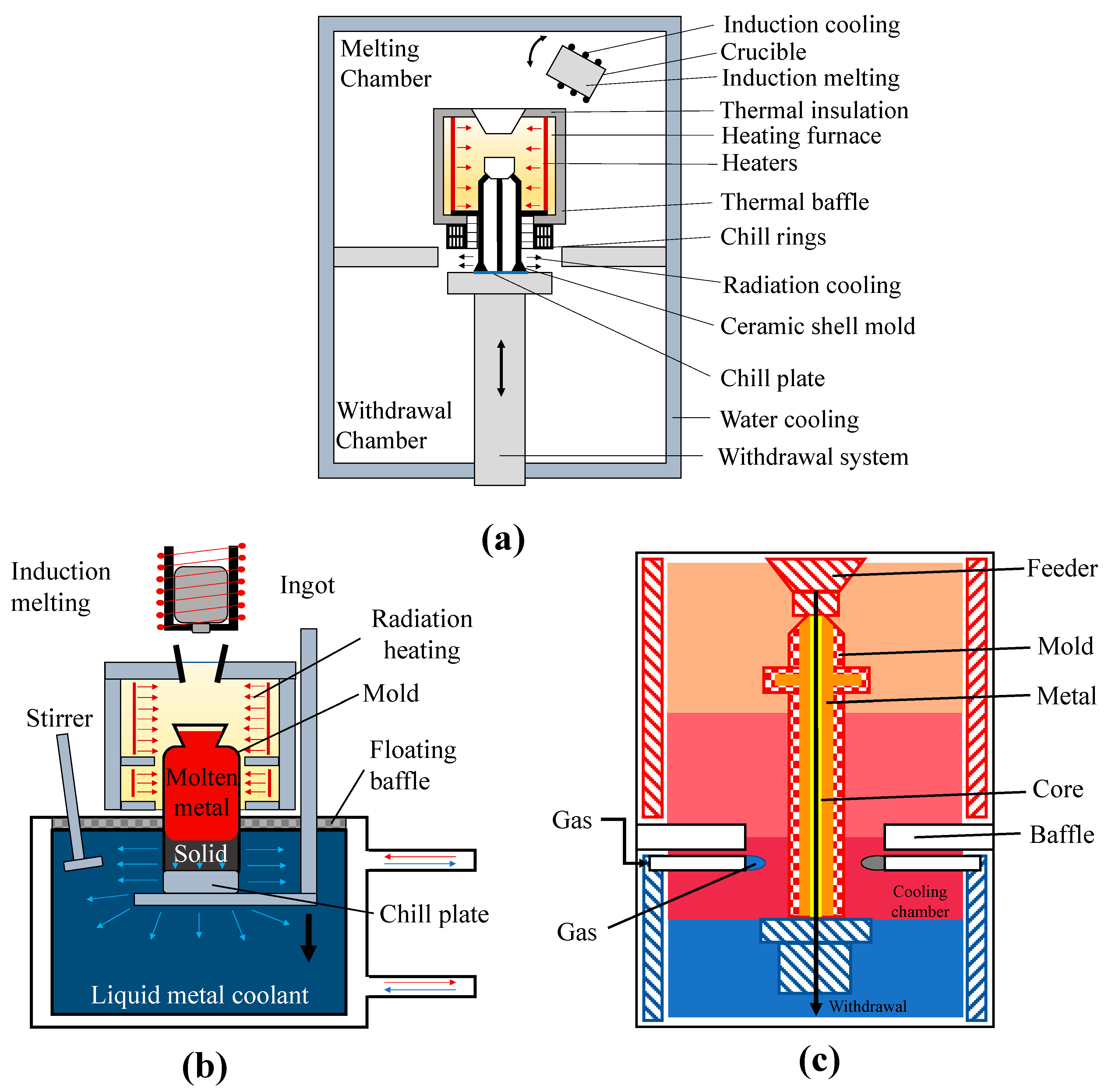
2.2.2. Investment Casting

Figure 6a illustrates the Bridgman process, which the turbine blade manufacturers currently employ to fabricate the SX turbine blades [28]. In the Bridgman process, a high positive thermal gradient (G) is created by moving the mold past the furnace’s radiation baffle in a precisely controlled manner. Such a high G is responsible for controlling the direction of the solidification in the fabricated part [21]. The high G is able to establish the direction of solidification along the axial direction by preventing the nucleation of EQ grains in the areas where the melt is undercooled [29,30]. Additionally, a higher G produces finer microstructure with small dendritic spacing, requiring less amount of time in homogenizing the microstructures via expensive heat treatment processes.
There are two individual chambers, divided by the radiation baffle, in the Bridgman furnace. The upper chamber is the heating zone and is responsible for heating the mold, and the lower chamber is the withdrawal chamber which is the cooling zone where the solidified casting moves during the solidification process. To begin the casting process, the mold is moved into the upper heating chamber where the temperature is held greater than the liquidus temperature of the casting material via a heater. The molten superalloy is transferred into the cast and then removed from the upper heating chamber via the radiation baffle and into the withdrawal chamber at a desired set rate, usually around a few millimeters per minute. This speed is set so that the solid-liquid interface can successfully progress without any instability. The pigtail shaped spiral grain selector has a small cross-section. This allows a single grain to enter the cavity of the casting. If a crystal seed is used in conjunction, the casting processing parameters must take into consideration that the seed is located at the bottom of the casting and that, if the seed is melted entirely, it would be unable to function and determine the growth orientation of the cast.
To improve the productivity of SX casting, liquid metal cooling-assisted casting (LMC) is developed with high G (Figure 6b) [21]. G is improved through the implementation of a liquid cooling bath where the mold and solidified casting are moved to during the withdrawal process. Additionally, the mold itself can be cooled by employing a liquid metal coolant. The application of this improved cooling process demonstrates significant promises in addressing the current issues of the Bridgman furnace in the fabrication of large scale SX blades [32,33,34,35]. When the blade dimensions become larger, it is increasingly difficult to maintain the required G to achieve SX solidification. The LMC process is generally able to obtain values of G that are double the values of G achieved via the Bridgman process. Al, Sn (tin), Ga (gallium)-In (indium) alloy, and Ga-In-Sn alloys are commonly used in the LMC process. However, the ceramic mold undergoes a significant thermal distress when it is submerged in the liquid bath. Hence, mold cracking can be a significant drawback of the LMC process. If the mold cracks, the liquid bath comes in contact with the cast and contaminate the SX blade [36]. Currently, the LMC process is not commonly found in the industrial field although it is able to produce a higher G and create a finer microstructure in the cast. The bottom line is that the advantages of the LMC process with regards to the casting quality are minimal, and the process itself is complicated and requires expensive equipment. Specifically, increasing the G often alters the axiality of the temperature gradient. The altered gradient in turn affects the solidification front’s curvature [33]. Therefore, G can become non-axial during the LMC process depending on how efficient the heat removal process is. Moreover, the lateral growth, because of removing the cast at a velocity that is too high or due to extreme geometry changes when the solidification front enters the cooling zone, is much more prominent in the LMC process than in the Bridgman process [21,33].
A third process, known as the gas cooling casting (GCC) process and illustrated in Figure 6c, is also developed for manufacturing the SX turbine blades [21]. This process has demonstrated many advancements compared to the Bridgman process. In GCC, an inert gas enters the furnace immediately underneath the baffle to assist in cooling the casting when it leaves the heating zone. As with the LMC process, GCC can obtain a G of twice the value of that found in the Bridgman process. However, some of the inert cooling gas may travel into the heating chamber due to the opening between the two furnace chambers and, consequently, lower the temperature in the heating zone as well as the alloy’s temperature gradient. This lowers the overall quality of the casting. Unfortunately, this problem cannot be easily and effectively eliminated, which has ultimately led to the prevention of the widespread employment of GCC among industrial manufacturers. In both LMC and GCC, the entire casting is aggressively cooled, beginning at the surface, via either a cooling liquid metal bath or inert cooling gas. However, due to the varying thicknesses displayed by the turbine blades, inhomogeneous cooling occurs. For example, the turbine blade’s trailing edge is encased in thinner mold walls compared to the location where the blade and the platform join. Therefore, the trailing edge is more significantly affected by the cooling processes used in LMC and GCC. In the end, this inhomogeneous cooling negatively impacts the stability of the casting process. Due to these challenges, the Bridgman process remains the most popular method for producing the SX turbine blades to date.

2.2.3. Heat Treatment

In order to optimize their microstructure and properties, the SX turbine blades are subjected to post-process heat treatments, which include homogenization, solutionizing, and aging and can vary depending on chemical composition, fabrication routes, and intended service conditions [4,37]. Homogenization, which is designed to produce recrystallized grain structures, and solutionizing, which is designed to dissolve age-hardening constituents and carbides into solid solution, are both high-temperature processes. Both are followed by aging, which is performed at intermediate temperatures to drive precipitation of a dispersed phase throughout the matrix to develop maximum strength [4,37]. These heat treatment procedures occur after the investment mold and ceramic cores have been removed. As with the developments of the SX turbine blades, their heat treatment procedures have also become complicated. Currently, there is a significant amount of interest in developing heat treatment procedures that require less time and energy. A recent US Department of Energy report estimates the energy usage of metal heat treatment in the US to be in the order of 270 TBTU [38]. The current heat treatment processes. that consist of solution treatment and aging, require ~22 h for stress relief, solution treatment, and aging process. To reduce the heat treatment cycle time and temperature, an in-depth understanding of the thermodynamics and the kinetics of the precipitate evolution process is necessary.

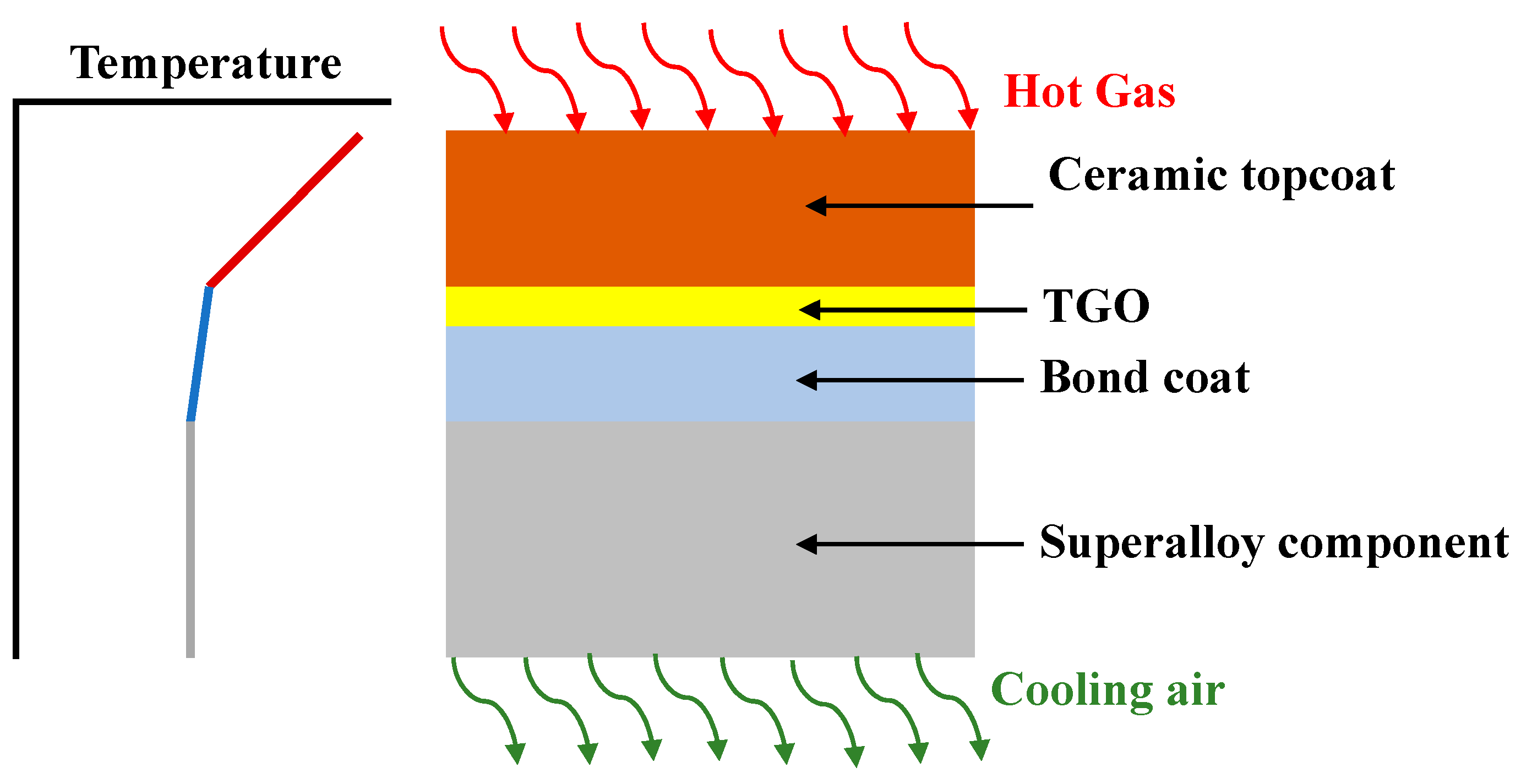
2.2.4. Thermal Barrier Coating (TBC)

Once SX blades are cast, after machining and heat treatment [39], TBC coating is applied on the blades. The coatings consist of three different layers i.e., bond coat, thermally grown oxide layer, and ceramic topcoat (Figure 7) [40]. Before the TBC coating process can begin, the surface of the SX blade is roughened using a procedure such as grit blasting. Grit blasting uses hard, angular particles to blast target surfaces and remove unwanted material. A few examples of particles used in grit blasting are walnut shells, various types of sand, silicon carbide, alumina, and emery. Not only does grit blasting effectively clean the SX blade’s surface, but it also increases the blade’s surface area by creating nooks and peaks which makes it easier and more receptive to coating. After grit blasting, the bond coat is deposited via one of two methods, plasma-spray, or electron-beam physical vapor deposition. The bond coat is an oxidative resistant layer composed of NiCrAlY or NiCoCrAlY alloy. During operation, when the aircraft engines experience their maximum operating conditions, the bond coat typically reaches temperatures higher than 700 °C. These higher temperatures directly cause oxidation of the bond coat resulting in the formation of a third layer, i.e., the thermally grown oxide (TGO) connecting the bond coat and ceramic topcoat [41].
The ceramic topcoat is responsible for thermally insulating the blade and is generally composed of yttrium oxide (Y2O3)-stabilized zirconium oxide (ZrO2) or YSZ [42,43]. YSZ displays a wide range of advantageous characteristics making it a favorable material for the topcoat. When compared to all other ceramics, YSZ displays one of the lowest thermal conductivities at high temperatures [44]. Additionally, this material contains a high level of point defects to help disperse the heat-conducting phonons referred to as the lattice waves. YSZ also naturally reduces the amount of stress being directly caused by the blade’s thermal expansion due to its high thermal-expansion coefficient [42,43]. Currently, there are two main methods used to produce TBCs: atmospheric plasma spray (APS) [45] and electron-beam physical vapor deposition (EBPVD) [46]. In APS, an arc made of high current is used to form a plasma jet composed of inert gas and powder particles. This plasma jet is used to cover the SX blade with molten particles, but it does not cover the inner region of the cooling channels. To cover the entire outer surface of the SX blade, there must be significant overlapping and layering of the splats. The individual splats harden quickly and independently which causes the resulting ceramic to have a certain level of porosity. The characteristics of the ceramic layer depend heavily upon the type of powder and the type of torch used in this process [45].
In EBPVD, a molten ceramic is evaporated to cover the outer surface of the SX blades [46]. First, the SX blade is preheated to a target temperature and then it is placed in a vacuum chamber. An electron beam melts and evaporates the chosen ceramic material. The evaporated ceramic creates a vapor cloud around the SX blade and then deposits on the SX blade’s outer surface and solidifies. To cover the entire surface of the SX blade completely and evenly, the blade must be rotated in the vapor cloud. For this to be a continuous process, the ceramic material is supplied into the crucible. The resulting ceramic layer consists of a columnar microstructure and can withstand a high amount of stress [46].
When it comes to comparing the ceramic layers produced by the two methods described above, EBPVD is preferred over APS [40,41,42,43]. EBPVD produces a smoother coating than APS which increases the aerodynamic capabilities of the SX blades. Moreover, due to the columnar microstructure of the EBPVD ceramic layer, this type of ceramic layer can withstand a higher amount of thermal stress. Additionally, EBPVD ceramic layers have better corrosion resistance. Finally, APS ceramic layers may cover the cooling holes in the SX blades. As a result, the cooling holes must be cleared after the TBC process is over, which requires an extra step of machining and processing, before the blades are ready to be used. During EBVPD, the cooling holes remain open and clear [40,41,42,43].

3. Failure Modes in SX Blades

Most of the damages encountered in the SX blades are caused during throttle movements that occur during take-off, climb, cruise, descent, and landing [47]. The mission profile (e.g., civil or military) and duration impact the throttle and, therefore, the blade life consumption (BLC). For example, in civil aviation, the shorter duration flights generally experience a higher rate of BLC per hour of operation compared to longer flights. While the degree of damage experienced by the SX blades also depends on how pilots individually operate the throttle, civil aviation observes a more consistent operation in throttle between two different pilots flying the same mission or two similar mission profiles because the flight requirements between each mission remain relatively consistent. In comparison, the throttle use varies more drastically between military aircraft even when used for the same mission profile. For example, two similar aircrafts flying a mission together encounter a noticeably different BLC. Specifically, when in formation, the aircraft at the top of the “V” experiences less BLC than an aircraft in the back of the formation. This is because the pilot at the lead generally needs to make fewer throttle movements in comparison to the rest of the aircraft in the formation [47].
For SX blades used in aircraft engines, mission profile factors not specific to the throttle movement can also affect BLC. Four such mission factors are the cruising Mach number, the cruising altitude, the duration of reheat (applicable to military aircraft with an afterburner), and the standard day temperature [47]. As the Mach number increases, blade deterioration is higher. As the cruising altitude increases, BLC increases exponentially. As the reheat time increases, an initial increase in BLC is observed. However, after this initial increase, a decrease in BLC occurs. As ambient temperature increases, BLC decreases in a linear fashion. Though it is possible to take measures to lower the degree of BLC, it is impossible to eliminate BLC [47]. SX blades used in commercial aviation currently have a lifespan of approximately 25,000 operating hours before they need to undergo a complete overhaul [48]. In 2019, American Airlines’ aircrafts averaged 9.92 block hours per day [48]. Block hours are defined as the time interval between an aircraft’s initial ramp under its own power) to its landing and arrival at the destination. Therefore, SX blades can last for about 6.90 years before needing to be scrapped. The primary modes of failures are low cycle fatigue (LCF), high cycle fatigue (HCF), fretting fatigue, creep, hot corrosion, coating failure, and combined modes. In the next sub-sections, these failure modes are discussed briefly.

3.1. Low Cycle Fatigue (LCF)

Extensive research exists to study LCF of SX components, specifically how the blade’s structural integrity is affected by its crystallographic orientation and temperature [49,50] for several nickel-base SX superalloys such as AM1 [51], DD6 [52], and SRR99 [53]. The alloys typically exhibit anisotropic behavior during cyclic deformation with different crystallographic orientations [54]. At higher temperatures, an [001]-oriented SX specimen displays cyclic softening during the initial stages of fatigue. Comparatively, a [111]-oriented specimen shows cyclic softening under higher levels of strain but shows cyclic hardening under lower levels of strain. The cyclic softening observed at the early stages of fatigue in the [001]- and [111] components is due to three things: the dissolution of γ′ precipitates, the formation of interfacial dislocation networks, and the elimination of dislocations. Under low strain, in the [111]-oriented specimens, cyclic hardening occurs when the dislocation arrays form in the γ matrix and align parallel to one another. These arrays obstruct dislocations from varying slip systems from interacting with one another. Therefore, the [111]-oriented SX turbine blades display a noticeably shorter fatigue life compared to [001]-oriented ones [54].
To reveal the underlying deformation mechanism, advanced materials characterization techniques, such as transmission electron spectroscopy (TEM), is extensively utilized to investigate the growth and development of dislocations as well as other defects, like stacking faults and twin/grain boundaries, after subjecting the SX turbine blades to different mechanical tests [54]. Research suggests that fatigue resistance is augmented by the uniform distribution of secondary γ′ precipitates in the γ matrix. The genesis of a fatigue crack is due to the formation of persistent slip bands (PSBs). After initiation, the fatigue crack continues to grow along the PSBs. When the specimen is under high temperatures and strain amplitudes, it generally undergoes a premature genesis because of the dislocation tangling as well as the continual coarsening of precipitates caused by an increased concentration of local stress intensity levels.

3.2. High Cycle Fatigue (HCF)

For both [001] and [111] crystallographic orientations, the presence of stress concentrators, such as notches, directly leads to a significant increase of BLC at a given temperature. Compared to LCF, SX components with varying crystallographic orientation do not demonstrate noticeable variations in their HCF life values [55]. SX components with both [001] and [111] crystallographic orientations show identical sensitivities to stress concentration factors. Smooth specimens show a fracture surface that contains many cleavage planes; one of these cleavage planes being significantly longer than the others. The orientation of these planes varies in their angle with respect to the plane of the minimum cross-section. Comparatively, the notched specimens’ fracture surfaces display no cleavage planes. These specimens fracture in a way that is highly comparable to the fracture behaviors observed in polycrystalline components [55].
A probable way in which the rough zone, defined as the cluster of multiple planar facets emerging from the crack initiation site, can form during HCF is the presence of stress concentration factors [56]. From a region, that is in proximity to a stress concentration factor, multiple slip bands are created when a fatigue test is performed. These bands are a direct result of the applied stress and the stress concentration factor. The presence of casting defects (e.g., pores and voids) can create high shear stress and stress intensity factor (SIF) applied to the slip systems. However, the SIF surrounding the pore or void region is less than the one describing the global SIF threshold of the specimen. In the regions surrounding the pore, severe microstructure shearing occurs. Comparatively, when the specimen is subjected to higher temperatures, the acute plastic deformation in these regions leads to recrystallization and cavitation. Additionally, TCPs and carbides are typically found to precipitate in the rough zone of certain superalloys; this occurrence is determined based upon the chemical compositions of the superalloys. As a result of the metallurgical characteristics, slip bands form further beyond where the pore could initially influence. Once the SIF of the rough zone becomes equivalent to the global SIF threshold, macroscopic HCF cracks form, and the SX components fail.

3.3. Fretting Fatigue

Fretting fatigue is the result of either cyclic bulk loading or an oscillating force being applied to two specimens, in contact with one another. These loads cause small-scale relative motion, generally lower than 100 μm, between the two specimens which, in turn, facilitates stress concentration and a steep stress gradient -at the contact surface [57]. Consequently, the material begins to degrade, and the rate at which the crack initiation occurs increases. As a result of the centrifugal and aerodynamic forces, fretting fatigue is most generally found in the joints and discs of the SX turbine blades [57]. The fretting fatigue behavior of the SX superalloy components has been studied significantly over the past five decades [58,59,60,61]. A considerable amount of data, including the in-situ fretting fatigue failure data at elevated temperatures, is available in the open literature. In-situ fretting fatigue tests demonstrate the evolution of crack initiation and propagation. Typically, such in-situ tests have been conducted in a scanning electron microscope (SEM) [62] and a synchrotron facility [63].
SX superalloy components possess the FCC crystal structure that has four {111} octahedral slip planes, each of which contains three <110> slip directions [64]. Therefore, in the SX components, there are twelve slip systems. The dislocations sail through the slips and the slips travel on the free surface. The results from an in-situ high-temperature fretting fatigue testing apparatus demonstrate that the density of the slip lines reduces with an increase in temperature [64]. Crystallographic orientation significantly alters the appearance of slip lines. As a result, the principal mode of deformations in SX components during fretting fatigue failure is the crystallographic fracture [65].

3.4. Creep

The creep characteristics of the SX superalloy components strongly depend on the average size, morphology, and volume fraction, and distribution of the γ′ precipitates [66,67] as well as the elastic modulus, microstructure, and lattice misfit of the γ/γ′ interface [68]. When a specimen is under thermal loads for a prolonged period, the size of the γ′ precipitates increases as a result of two different mechanisms: (i) the Ostwald ripening [69] and (ii) the formation of directional γ′ clusters due to the loss of its cuboidal shape [70]. A decrease in the γ/γ′ interface area, the modulus misfit, and the γ/γ′ lattice mismatch strain play a critical role in the γ′ coarsening [71]. Consequently, precipitates are no longer coherent, and the component’s high-temperature strength is severely decreased. In several superalloys, such as CMSX-10®, while under prolonged thermal exposure, the primary determinant influencing and decreasing creep properties is considered to be γ′ precipitate coarsening [71]. While employed, turbine blades made of the fourth generation SX superalloys experience non-homogeneous heating due to skewed combustor exit thermal profile and pattern factors. Consequently, these blades demonstrate a prolonged serviceability temperature of approximately 1000–1100 °C even though the temperature capabilities of this superalloy are approximately 1140–1150 °C [39].
The microstructure of an experimental SX superalloy after undergoing a general heat treatment shows the formation of γ′ precipitates in the γ matrix [39]. The cuboidal γ′ precipitates demonstrating a large volume fraction (~66.53%) are homogeneously dispersed in the γ matrix. After subsequently exposing the experimental superalloys to 1000 °C for 100 h, 500 h, and 1000 h, their resulting microstructures are displayed in Figure 8a through 8c. The γ′ precipitates’ size steadily increases as aging time progresses, and the specimen’s morphology remains cuboidal which demonstrates the stability of the microstructure [39]. The creep curves at 1000 °C for 100 h, and at 1140 °C/137 MPa for 500 h and 1000 h exhibit three individual stages where the duration of the second stage was responsible for most of the creep process [39]. The microstructures of the specimens after experiencing rupture due to creep at 1140 °C and 137 MPa are displayed in Figure 8d through Figure 8f. The cuboidal precipitate structure is lost. The dislocation networks are observed at the γ/γ′ interface and annotated by arrows in Figure 8g through Figure 8i [39]. Existing studies reinforce that the appearance of dislocation networks is critical in deciding the creep life [72].

3.5. Hot Corrosion

In gas turbines, turbine blades experience some level of hot corrosion; it is when the metal temperatures are less than ~900 °C that the rate of oxidation is relatively low [73]. Comparatively, in gas turbine engines with high thrust ratings, the SX turbine blades experience a higher rate of hot corrosion that has the potential to significantly decrease BLC [74]. A liquid, generally sulphate, is typically deposited on the turbine blades’ surface for hot corrosion initiation. This deposit depends on both the gas streams as well as the reactive gas species, such as SO2, SO3, and HCl, because of the trace metal species, like sodium compounds, they contain [73]. There are four main factors that affect the rate of hot corrosion experienced by the SX blades: the rate at which the deposit forms, what material the deposit is composed of, the temperature of the metal, and what material the surrounding environment is composed of. There are two types of hot corrosion failure identified in SX blades [75,76]: Type I hot corrosion which occurs around ~750–900 °C, and Type II hot corrosion which is experienced at ~600–800 °C. Certain contaminant species, such as species containing sulfur, chlorine, alkali metals (e.g., Na and K), as well as other trace metals (e.g., Pb and Zn), have a high impact on the corrosive degradation experienced by the SX blades. Because the concentration of these contaminants varies in different fuels used in gas turbine blades, varying degrees of hot corrosion is experienced with each element/fuel utilization process when the gas streams get to the SX turbine blades [73].
Generally, uncoated SX blades experience a higher degree of mass gain, resulting from hot corrosion reactions, than coated SX blades do [73]. These changes in mass observed in both coated and uncoated materials are responsive to the flux that they experience [77]. Moreover, it has been found that the degree of mass change experienced by the SX blade is more sensitive to certain gases than others. Specifically, mass change responds more severely to changing SO2 levels in the surrounding environment than to HCl levels. Specifically, high concentrations of SO2 cause more damage than low concentrations of SO2 when HCl is present. Additionally, water vapor has a considerable effect on the mass gain experienced by the SX blades.
Uncoated SX components typically show very high degradation rates which highlights how necessary it is for these components to be appropriately coated before employment. The composition of the SX superalloy has a significant impact on the functioning of a coating (i.e., Pt-Al) when the turbine blades are subjected to a temperature of 700 °C for 500 h and a deposition flux of 15 µg/cm2/h in air having 50 PPM SOx [73]. A SX turbine blade made of CMSX-4® superalloy experiences a more localized Type II pitting attack where the pitting can perforate the Pt-Al coating and subsequently penetrate the alloy under this coating. Comparatively, an SX turbine blade made of SC2-B coated in Pt-Al experiences a more broad-fronted attack where the perforation manages to travel less than halfway through the thickness of the coating. The reason for the corrosion variation in these two SX blades is because the “effective” composition of the Pt-Al coating is different for these two blades. Specifically, the material that the blade is composed of alters the composition of the Pt-Al coating via interdiffusion [73]. Therefore, to optimize the level of hot corrosion experienced by SX blades, it is necessary to understand the coupled reactions of varying combinations of turbine materials and coatings.

3.6. Coating Failure

TGO growth is the primary cause of TBC spallation failure [40]. For example, TGO growth can cause constrained volume expansion leading to compressive stresses. Under cooling, the misaligned thermal-expansion observed in the TGO and bond coat directly causes high levels of residual thermal compressive stresses resulting in the fracture driven by the TGO growth [78,79]. The formation and growth of different metallic oxides, involving Al, Ni, and Cr, make up the quality of the TGO structure and give rise to quick oxygen-diffusion paths which ultimately increase the rate of localized oxidation [80]. As a result of the bond coat’s cyclic creep, which takes place as thermal cycling progresses, the bond-coat/TGO/topcoat interfaces experience continual roughening [81]. In a bond-coat/TGO interface (EBPVD TBC), that is considered nominally flat, roughening occurs because of the TGO perforating the bond-coat [82]. Comparatively, in an interface that is not flat (APS TBC), also known as an undulated interface, the amplitude of the undulation increases [83]. This increase results in stresses that are out-of-plane and perpendicular to the metal/ceramic interface which in turn leads to TBC failure. As the TGO thickens, thermal-expansion misalignment in the bond coat/TGO interface causes stresses that become the dominated stress when compared to the thermal stresses. After the TGO reaches a certain width, the bond coat/TGO’s thermal-expansion coefficient is less than the individual coefficients of the topcoat and the bond coat; this causes the inverse, from compressive to tensive, of the topcoat’s stresses located in its undulation trough. Consequently, this inversion leads to crack formation between the crests, also known as the valleys, in the topcoat.
The topcoat in EBPVD TBCs displays a higher strain tolerance than that of APS TBCs, so the multiple cracking events in the EBPVD TBC systems take place at the interfaces of either the bond coat/TGO or the TGO/topcoat. EBPVD mainly undergo three types of failure methods, such as (i) Mechanism I: the bond coat/TGO interface separates from one another (similar to APS TBC case); (ii) Mechanism II: the interface of the TGO/topcoat separates and TGO perforates bond coat due to either TGO roughening as a result of cyclic bond coat or the increased rate of embedded oxide formation and cavity formation in the bond coat; and (iii) Mechanism III: fracture in the interface as a result of interfacial toughness degradation resulting from fatigue as well as the movement of unwanted elements (e.g., sulfur) to the interface [40]. In APS, there are four different failure mechanisms [40]. These mechanisms are (i) Mechanism I: the interface of the bond coat/TGO experiences cracking, located at the crests, due to tensile stresses; (ii) Mechanism II: the interface of the TGO/topcoat experiences fracturing, located at the crests, as a result of tension; (iii) Mechanism III: near the location of the crests, cracking of the topcoat which is extremely brittle, occurs; and (iv) Mechanism IV: in the valleys located in between the crests, topcoat cracks [40]. The dominant mechanism depends on the blade material and coating combinations as well as the operating environment.

4. Material Recovery from Scrapped or Defective Blades

Nickel-base SX cast superalloys are generally composed of at least ten alloying elements (Table 1) to optimize their performance for high-temperature operation [6]. Among the alloying elements, Re deserves a special mention as it provides the SX blades with superior rupture strength at high temperatures. Over the past few decades, a significant increase in Re percentage in SX alloys is carried out. This element is not used in the first generation SX superalloys. The second and third generation SX superalloys contain approximately 3 wt.% and 6 wt.% Re, respectively [6]. The fourth generation is composed of Re at an equal level to the third generation. Despite accounting for only 3–6 wt.%, the cost of Re is approximately ten times as expensive as the price of the remaining 97 wt.% of the alloying elements because of its low crustal abundance at only 0.7–1.0 parts per billion. Moreover, as the airline industry grows, the demand for Re grows with it. Consequently, the cost of Re increases. In 2006, GE aviation began a program encouraging the reduction of the company’s dependence on Re because they foresaw that the need for Re would increase while the supply of Re would remain relatively constant. The price of Re increased by more than 100% between 2006 and 2008. Despite GE’s efforts, 78% of the world’s Re is currently being used in the production of SX superalloys.
Both the high cost and low crustal abundance of Re demonstrates the requirement to retrieve Re from scrapped blades using a process called ‘revert’ [84]. Revert seeks to reclaim the blade’s elemental components. Unfortunately, it is impossible to reclaim all the original material. Moreover, reclaimed material must meet a certain standard, as set by the industry, to be employed again. Because of these standards, not all reclaimed material is able to return to the industry that originally employed it. Moreover, the reverting process can be complicated, time-consuming, and expensive. In general, the more expensive and complicated a process is, the greater the percentage of recovered material, and the higher the quality of the recovered material. However, for many companies, the downsides of reverting outweigh the benefits, and the higher quality reverting processes are not implemented.
One of the simplest reverting techniques is re-melting a decommissioned alloy directly into a new charge of melted alloy. However, during this process, approximately 20% of the potential recovery material is lost due to high burn-out and oxidation. This high loss of material causes this process to be undesirable to many companies despite the process’s simplicity. Comparatively, by combining a re-melting process with multiple refinement methods (e.g., vacuum refinement), better results can be achieved. This process is usually high in energy consumption and/or economically unfeasible depending on how the material is re-melted and how many times, and what type of refinement is used. The second option is to use hydrochloric acid (HCl) leaching which is a hydrometallurgical process. The first step in this revert procedure uses HCl to leach Ni, the base alloy in SX superalloys, as well as the elements used to form the thermal barrier: Al, Cr, Co, and W. The second step uses chlorine (Cl) to recover Re. This method of HCl leaching shows a lot of promise to be employed in the future. Compared to the re-melting process, leaching is more sustainable and generally recovers a larger percent of the material [84]. Specifically, one study found a recovery of > 99% for both Re and Ni [85].

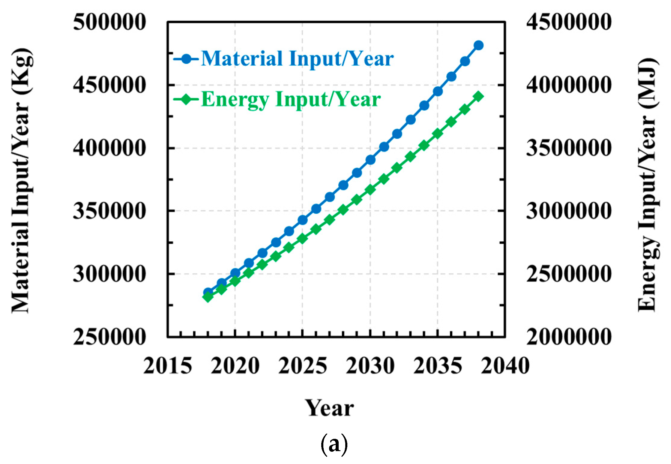
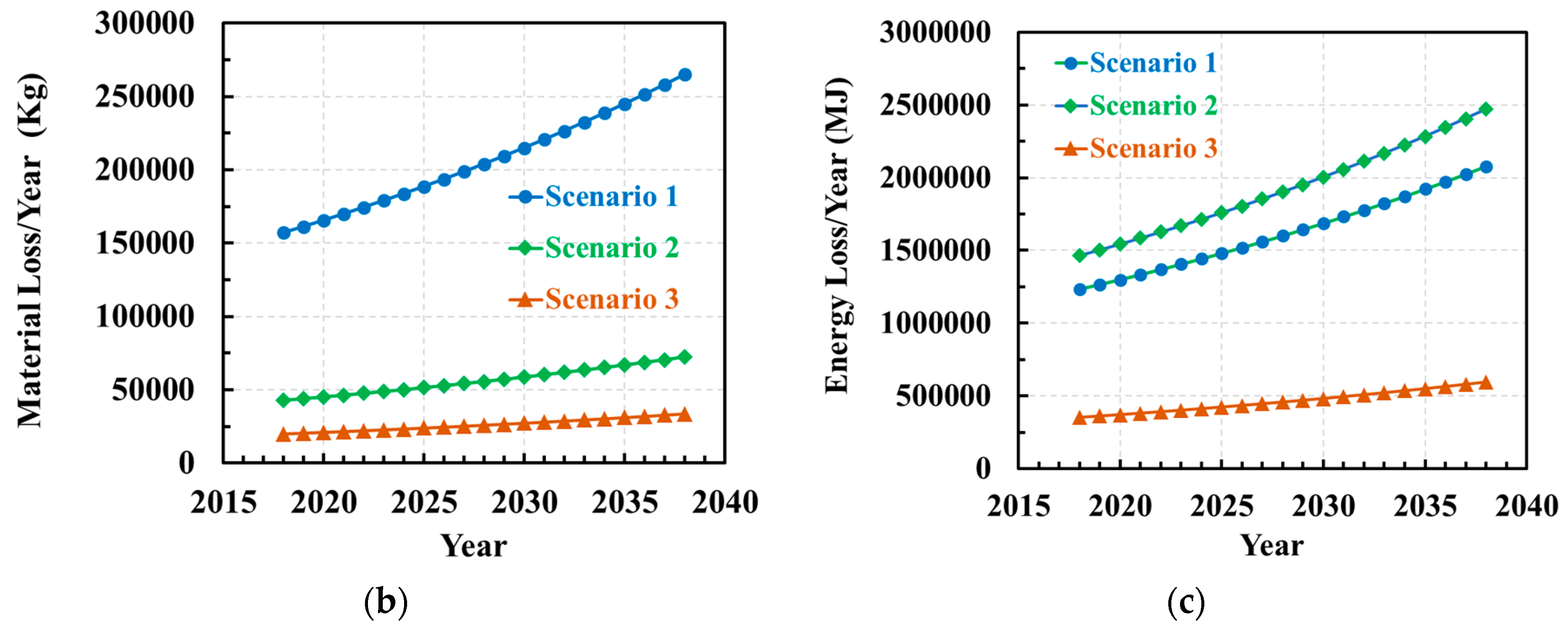
5. Energy and Material Waste During Revert and Scarp—A Case Study

To perform the necessary calculations to estimate the energy and material waste during the manufacturing of replacement turbine blades, it is necessary to make certain assumptions. These assumptions are summarized as:
  • An increase in number of aircrafts from 23,904 in 2018 to 40,301 in 2038 [86].
  • The average block hours per aircraft per day is 10 [48].
  • Turbine blade specifications are taken from the Boeing 787-9 which uses two GEnx-1b74/75 engines/aircraft [87].
    This engine contains two rows of high-pressure turbine blades with 62 SX blades in each row.
    CMSX-4® is treated as the material for the SX blades and the blades are approximately 0.33 kg each.
  • For every metric ton of usable SX casting produced, 8116 MJ of energy is used [88].
  • 36% savings in total energy due to single repair over replacement [89]. Hence, 5194 MJ of energy is required per metric ton of repair.
  • For every metric ton of good revert, 8116 MJ of energy is used [88]. Half of this amount is due to repair and the other half due to revert.
  • Approximately 10% of all SX blades are defective and must be scrapped without ever being used. Only 20% of the scrapped blade material is recoverable through revert to the desired quality [84].
  • The lifespan of the SX is 25,000 operating hours before they need some degree of repair. Three scenarios are considered for material and energy waste analysis:
    5% material loss due to damage [89]. Two cycles of repair [90]. No revert.
    5% material loss due to damage [89] and 20% material loss during revert [84]. Two cycles of repair [90].
    5% material loss due to damage [89] and 20% material loss during revert [84]. If efficient repair methods are available, the blades may be restored multiple times. For demonstration purposes, the number of repair cycles is selected as 10.
After making these assumptions, the energy and material input needed to produce the total number of SX turbine blades for commercial aircraft are calculated from 2018 to 2038. As illustrated in Figure 9a, an average increase of approximately 68% in both material and energy input required from 2018 to 2038. Figure 9b shows the amount of material waste considering three different scenarios. The green curve assumes that scrapped blades go through a revert process whereas the blue curve assumes that the scrapped blades do not go through a revert procedure. There is approximately a 72% decrease in material waste if a revert is employed compared to when the blade is directly discarded. These numbers may be further reduced if the blades can be repaired to their original integrity as demonstrated by the saffron curve where it is assumed that the blades can be repaired 10 times. Figure 9c shows the energy loss for the three different scenarios. It is interesting to note that the scenario 2 (indicated by the green curve) has higher energy loss because the revert process consumes a large amount of energy due to its complexity. The amount of energy loss is significantly reduced only when the number of repair cycles is large enough. This case study shows that by developing an efficient repair method that can restore the blades to their original integrity multiple times, the material and energy loss may be decreased by a whopping 87% and 71%, respectively.

6. Turbine Blade Repair via Additive Manufacturing (AM)

Although metal additive manufacturing (AM) procedures are all rooted in the common idea of fusing layer upon layer of material, each process is distinct and can vary because of the type of energy source employed, the processing techniques used, the conditions under which the procedure is conducted, the materials it uses, and the metallurgical consolidation mechanisms used [91]. Due to these variabilities, metal AM processes can be classified into several different categories as illustrated in Figure 10. In this figure, the available metal AM processes are first organized by their energy source and then by their feedstock type. There are three main types of energy sources such as a laser, an electron beam, or an arc, while there are two different types of feedstock such as, powder or wire. Despite the availability of different types of metal AM processes, based on the literature reviewed, only a handful of them, as schematically shown in Figure 10, are being successful in repairing SX components to date.
The most used arc welding-based procedures are gas tungsten arc (GTA) welding, tungsten inert gas (TIG) welding, electron beam (EB) welding, and laser welding. Each of these processes is typically subjected to the same limitations in producing SX microstructure and crack formation [92,93,94]. Stueber et al. [95] tried to minimize the crack formation by heating the weld adjacent zone to a temperature greater than the aging temperature while still being less than the incipient melting temperature. United Technologies attempted a two-step process for the welding. The first step deposited filler metal into the repair, and in the second step, a broad and shallow melt pool was created by using a defocused beam to obtain epitaxial SX microstructure from the substrate to the top of the deposit [96]. Hence, this method is typically suited for local repair on simple contours. Different methods have, since then, been tried in order to repair components having complex shapes [97,98,99]. Laser welding and EB welding of superalloys such as CMSX-4® were shown to be less susceptible to cracking and the formation of stray grains compared to GTA welding.
The electron beam powder bed fusion (E-PBF) process showed encouraging results with the repair of René 142 [103]. Additionally, SX CMSX-4® was also processed via E-PBF. The microstructure of CMSX-4® grew epitaxially from the substrate [104]. While the E-PBF processes used a multi-layer deposition strategy, laser PBF (L-PBF) processes were successful in producing repairs with a deposit thickness greater than 1500 μm, with no cracks, using only a single-pass, and for several SX alloys, such as CMSX-4® [100,105,106] (Figure 11a), René 142 [11,107], and René N5 [108,109]. L-PBF processes also showed success in repairing heterogeneous material systems e.g., deposition of SX René 142 on René N5 [11]. Various laser-based DED (L-DED) processes were extensively used to successfully repair SX components made of CMSX-4® [102], DD6 [110], IC221W [111], René N4 [112], and René N5 [113]. L-PBF processes have high cooling rates, varying between ~104 and 106 Ks−1. On the other hand, processes like E-PBF use a hotbed (>870 K), which reduces the cooling rate, and hence do not produce a fine microstructure like L-PBF [91]. The cooling rate of L-DED is also lower due to its lower scan speed. Hence, the microstructure produced by L-PBF [105] is finer than E-PBF [104] and L-DED [102]. The repair regions typically display three individual sections: (i) epitaxial dendritic growth going in the [001] direction; (ii) epitaxial dendritic growth going in the [100] direction which is the direction in which the beam is traveling); and (iii) stray grains (SGs) [11].
Owing to the difficulties of processing the SX superalloys, most of the AM repair research has so far been focused on how to avert processing defects such as cracks and pores [114]. With regards to mechanical property evaluation, much of the work reports the microhardness values in the repair region [2]. In the majority of cases, the repair region showed higher hardness values than the substrate region because the microstructure of the repair region has a finer microstructure compared to the substrate region [2]. The tensile testing of SX repairs showed interesting behaviors [115]. The tensile failure at moderate temperatures showed cleavage fracture where the coarse carbides, in the substrate area, not only cracked but aided the crack propagation. This made the substrate region to be the weakest. However, at high temperature, the fracture took place due to the eutectics and porosities in the deposited area, thus, making the deposit area vulnerable to tensile failure. In both these cases, the joint region (i.e., the substate and the AM deposit interface) did not fracture [115].

7. Conclusions

The ever-increasing concerns over global emissions and resource depletion have inspired a greater effort on investigating and employing innovative procedures for manufacture and repair of the SX turbine blades to reduce the environmental impacts. The importance of repair can be easily appreciated by considering the results published by the Department of Defense, United States that estimates over $100 million worth components amenable by repair using AM [116]. While existing research shows progress on the fabrication and of SX components, significant scientific and technical challenges still exist. Based on the literature reviewed in this article, these challenges are segmented into four different categories as summarized below.
  • Materials:
    The SX turbine blade materials contain more than ten alloying elements to optimize their performance for high-temperature applications. Traditionally, the alloy development process has been based on trial and error. For example, it took more than a decade to develop CMSX-4® [117]. An integrated computational materials engineering (ICME) science approach needs to be matured to reduce the alloy development cycle [118]. The SX superalloys are also developed and optimized for casting operation. Existing literature shows that due the non-equilibrium nature of AM process, the deposits formed through AM produces additional defects such as the presence of non-equilibrium phases [91]. The SX alloys, therefore, need to be optimized for AM. However, fabrication of new alloys is quite a challenging task and there is no inexpensive way to fabricate new alloys that are suitable for AM. Existing literature also shows issues with powder feedstock variability. For example, Engeli et al. [119] showed significant variations in the powder size, morphology, and composition between different batches of IN738LC powder obtained from different vendors resulting in large differences in hot cracking susceptibility, pore formation, and processing window among different batches of powder.
  • Manufacturing via Investment Casting
    The investment casting process depends on the shells and cores whose quality depends on several factors, including the strength of the mold relative to the solidifying alloy, thermal shock resistance, dimensional stability, leachability, reactivity, permeability, and cost. Future research is required to develop new ceramic mold materials, processing, and characterization methods. So far, the Bridgman process has shown a tremendous success in fabrication the SX turbine blades. However, thermal gradient control is a critical issue for large blades. More research is required to address this issue. Finally, after fabrication, the blades need to be post processed using heat treatment to homogenize the microstructure. Higher thermal gradient helps in achieving a finer microstructure that would show a less degree of elemental segregation which would cut down the heat treatment time significantly.
  • Repair via AM
    Repair of SX components using AM is susceptible to different types of deposit defects such as pores, cracks, CET, OMT, and SGs. One approach to mitigate such defects is to develop process maps that essentially show various process parameter pairings for which specific types of defect are either prevented or inconsequential [120,121,122]. Existing literature shows that some of these defects are inversely correlated [105]. Higher energy density decreases the surface tension and causes a smoother flow of powder decreasing the number of SGs. However, the expanded melt pool results in a reduced vertical temperature gradient and consequently lowers the SX height. Developing process maps by altering process parameters to mitigate defects is, therefore, not very conducive and robust feedback control methodologies are required for improving the repair quality.
    Repair of SX components using AM is so far focused on simple geometries such as rectangular blocks [104,105]. Turbine blade geometries are extremely complex due to the presence of numerous internal cooling channels [3]. Repair of such complex geometry blades require tighter control of the process parameters. In addition, finer laser or electron beam spot size is also required to fabricate parts having micron scale resolution. Frequently, if not always, thin geometrical features suffer from warpage due to residual stress buildup during thermal cycling inherent in AM [105]. AM surfaces are also an order of magnitude rougher than the cast surface [123]. Currently, no effective methods exist for reducing the roughness of the internal surfaces.
  • Part Inspection:
    -Process development for microstructure control in SX parts is significantly held back because of limitations in current characterization techniques. Orientation imaging microscopy (OIM), which is an electron backscatter diffraction (EBSD) method, is typically used to validate whether an AM process can successfully deposit SX microstructure. While OIM is an excellent tool, it suffers from the requirements of sectioning (destroying) the parts to provide millimeter scale samples that fit the envelope of the scanning electron microscope (SEM). In doing so, the researcher is forced to decide on whether a handful of mm-scale samples, which can take days to characterize, is representative of the entire part. This problem is greatly amplified when one has several parts to characterize. In some cases, it is likely that hundreds of parts are needed to be built, characterized, and analyzed to truly understand the process and the resultant microstructures. One of the alternate approaches is to use ultrasonic [124] or acoustic [125] inspection techniques that can assess if the microstructure is SX. However, currently the resolution of such inspection is unsatisfactory, and more work is required for non-destructive testing (NDT) of SX parts.

Author Contributions

Conceptualization, A.B.; methodology, N.M.A. and A.B.; formal analysis, N.M.A.; resources, A.B.; writing—original draft preparation, N.M.A.; writing—review and editing, A.B.; visualization, N.M.A. and A.B.; supervision, A.B.; funding acquisition, A.B. All authors have read and agreed to the published version of the manuscript, please turn to the CRediT taxonomy for the term explanation.

Funding

We graciously acknowledge the Drawdown Program at Pennsylvania State University for the financial support.

Acknowledgments

We would like to acknowledge John Apostle, Principal Engineer—GEnx Program, American Airlines, Dallas, TX, USA for his help in providing necessary information regarding the GEnx-1b74/75 engine.

Conflicts of Interest

The authors declare no conflict of interest.

References

  1. Bathie, W.W. Fundamentals of Gas Turbines; John Wiley & Sons: Hoboken, NJ, USA, 1984. [Google Scholar]
  2. Basak, A. Advanced Powder Bed Fusion-Based Additive Manufacturing with Turbine Engine Hot-Section Alloys through Scanning Laser Epitaxy. Ph.D. Thesis, Georgia Institute of Technology, Atlanta, GA, USA, 2017. [Google Scholar]
  3. Kaewchoothong, N.; Maliwan, K.; Nuntadusit, C. Numerical simulations on low and heat transfer in ribbed two-pass square channels under rotational effects. In IOP Conference Series: Materials Science and Engineering, Proceedings of the Computational Fluid Dynamics in Research and Industry (CFDRI 2017), Songhkla, Thailand, 3–4 August 2017; IOP Publishing: Bristol, UK, 2017; p. 012004. [Google Scholar]
  4. Donachie, M.J.; Donachie, S.J. Superalloys: A Technical Guide; ASM International: Novelty, OH, USA, 2002. [Google Scholar]
  5. Dai, H.; Gebelin, J.; Newell, M.; Reed, R.; Brown D’Souza, N.P.; Dong, H. Grain selection during solidification in spiral grain selector. In Proceedings of the Superalloys 2008, Champion, PA, USA, 14–18 September 2008; pp. 367–374. [Google Scholar]
  6. Pollock, T.M.; Tin, S. Nickel-based superalloys for advanced turbine engines: Chemistry, microstructure and properties. J. Propuls. Power 2006, 22, 361–374. [Google Scholar] [CrossRef]
  7. Schilke, P.; Foster, A.; Pepe, J. Advanced Gas Turbine Materials and Coatings; General Electric Company: Boston, MA, USA, 1991. [Google Scholar]
  8. Whitney, P. Pratt & Whitney’s Single Crystal Turbine Blade Named Historic Mechanical Engineering Landmark; Pratt & Whitney: East Hartford, CT, USA, 2018. [Google Scholar]
  9. Mevissen, F.; Meo, M. A review of NDT/structural health monitoring techniques for hot gas components in gas turbines. Sensors 2019, 19, 711. [Google Scholar] [CrossRef] [PubMed] [Green Version]
  10. Cooper, T. 2017–2027 Fleet & MRO Forecast. Available online: https://www.oliverwyman.com/our-expertise/insights/2017/feb/2017-2027-fleet-mro-forecast.html (accessed on 3 October 2020).
  11. Basak, A.; Acharya, R.; Das, S. Epitaxial deposition of nickel-based superalloy René 142 through scanning laser epitaxy (SLE). Addit. Manuf. 2018, 22, 665–671. [Google Scholar] [CrossRef]
  12. Decker, R.; Mihalisin, J. Coherency strains in gamma prime hardened nickel alloys. ASM Trans. Quart. 1969, 62, 481–489. [Google Scholar]
  13. Yoo, M. On the theory of anomalous yield behavior of Ni3Al-Effect of elastic anisotropy. Scr. Metall. 1986, 20, 915–920. [Google Scholar] [CrossRef]
  14. Gregori, A. A Survey of Welding and Repairing of Nickel Superalloys for Gas Turbines; TWI Core Research Program: Cambridge, UK, 2003; p. 774. [Google Scholar]
  15. Cannon Muskegon Vacuum Alloys. Available online: https://catalog.cannonmuskegon.com/vacuum (accessed on 27 September 2020).
  16. Betteridge, W.; Shaw, S. Development of superalloys. Mater. Sci. Technol. 1987, 3, 682–694. [Google Scholar] [CrossRef]
  17. Swaminathan, V.; Cheruvu, N. Advanced Materials and Coatings for Combustion Turbines. In Proceedings of the ASM 1993 Materials Congress Materials Week’93, Pittsburgh, PA, USA, 17–21 October 1993. [Google Scholar]
  18. Seth, B. Superalloys: The utility gas turbine perspective. Superalloys Metall. Appl. 2000, 2000, 3–16. [Google Scholar]
  19. Erickson, G.; Harris, K. DS and SX superalloys for industrial gas turbines. In Materials for Advanced Power Engineering; Kluwer Academic Publishers: Liege, Belgium, 1994; pp. 1055–1074. [Google Scholar]
  20. Groover, M.P. Fundamentals of Modern Manufacturing: Materials Processes, and Systems; John Wiley & Sons: Hoboken, NJ, USA, 2007. [Google Scholar]
  21. Ma, D. Novel casting processes for single-crystal turbine blades of superalloys. Front. Mech. Eng. 2018, 13, 3–16. [Google Scholar] [CrossRef] [Green Version]
  22. Thong, T.A. MA2700 Continual Assessment Case Study Report. 2013. Available online: https://www.academia.edu/8858634/Turbine_blade_manufacturing_overview (accessed on 26 October 2020).
  23. Swanson, G.; Arakere, N. Effect of crystal orientation on analysis of single-crystal, nickel-based turbine blade superalloys. Mater. Sci. 2000, 124, 161–176. [Google Scholar]
  24. Li, Y.; Liu, L.; Huang, T.; Zhang, J.; Fu, H. The process analysis of seeding-grain selection and its effect on stray grain and orientation control. J. Alloys Compd. 2016, 657, 341–347. [Google Scholar] [CrossRef]
  25. Langston, L.S. Single-Crystal Turbine Blades Earn ASME Milestone Status; Pratt & Whitney: East Hartford, CT, USA, 2020. [Google Scholar]
  26. Power, D. Palladium alloy pinning wires for gas turbine blade investment casting. Platin. Met. Rev. 1995, 39, 117–126. [Google Scholar]
  27. Cui, K.; Wang, W.; Jiang, R.; Zhao, D. Layout optimization method for core holders in wax pattern mold of hollow turbine blade. Int. J. Adv. Manuf. Technol. 2018, 98, 1031–1045. [Google Scholar] [CrossRef]
  28. Hofmann, N.; Olive, S.; Laschet, G.; Hediger, F.; Wolf, J.; Sahm, P.R. Numerical optimization of process control variables for the Bridgman casting process. Model. Simul. Mater. Sci. Eng. 1997, 5, 23–34. [Google Scholar] [CrossRef]
  29. Bridgman, P.W. Crystals and their Manufacture. U.S. Patent 1,793,672A, 24 February 1931. [Google Scholar]
  30. Pratt, D. Industrial casting of superalloys. Mater. Sci. Technol. 1986, 2, 426–435. [Google Scholar] [CrossRef]
  31. Kubiak, K.; Szeliga, D.; Sieniawski, J.; Onyszko, A. The unidirectional crystallization of metals and alloys (turbine blades). In Handbook of Crystal Growth; Elsevier: Amsterdam, The Netherlands, 2015; pp. 413–457. [Google Scholar]
  32. Tschinkel, J.; Giamei, A.; Kearn, B. Apparatus for Casting of Directionally Solidified Articles. U.S. Patent 3,763,926A, 9 October 1973. [Google Scholar]
  33. Giamei, A.F.; Tschinkel, J.G. Liquid metal cooling: A new solidification technique. Metall. Mater. Trans. A 1976, 7, 1427–1434. [Google Scholar] [CrossRef]
  34. Elliott, A.J. Directional Solidification of Large Cross-Section Ni-Base Superalloy Castings via Liquid-Metal Cooling. Ph.D. Thesis, University of Michigan, Detroit, MI, USA, 2005. [Google Scholar]
  35. Liu, L.; Huang, T.; Qu, M.; Liu, G.; Zhang, J.; Fu, H. High thermal gradient directional solidification and its application in the processing of nickel-based superalloys. J. Mater. Process. Technol. 2010, 210, 159–165. [Google Scholar] [CrossRef]
  36. Zhang, J.; Lou, L. Directional solidification assisted by liquid metal cooling. J. Mater. Sci. Technol. 2007, 23, 289–300. [Google Scholar]
  37. Reed, R.C. The Superalloys: Fundamentals and Applications; Cambridge University Press: Cambridge, UK, 2008. [Google Scholar]
  38. Chapas, R.B.; Colwell, J.A. Industrial Technologies Program Research Plan for Energy-Intensive Process Industries; Pacific Northwest National Lab. (PNNL): Richland, WA, USA, 2007. [Google Scholar]
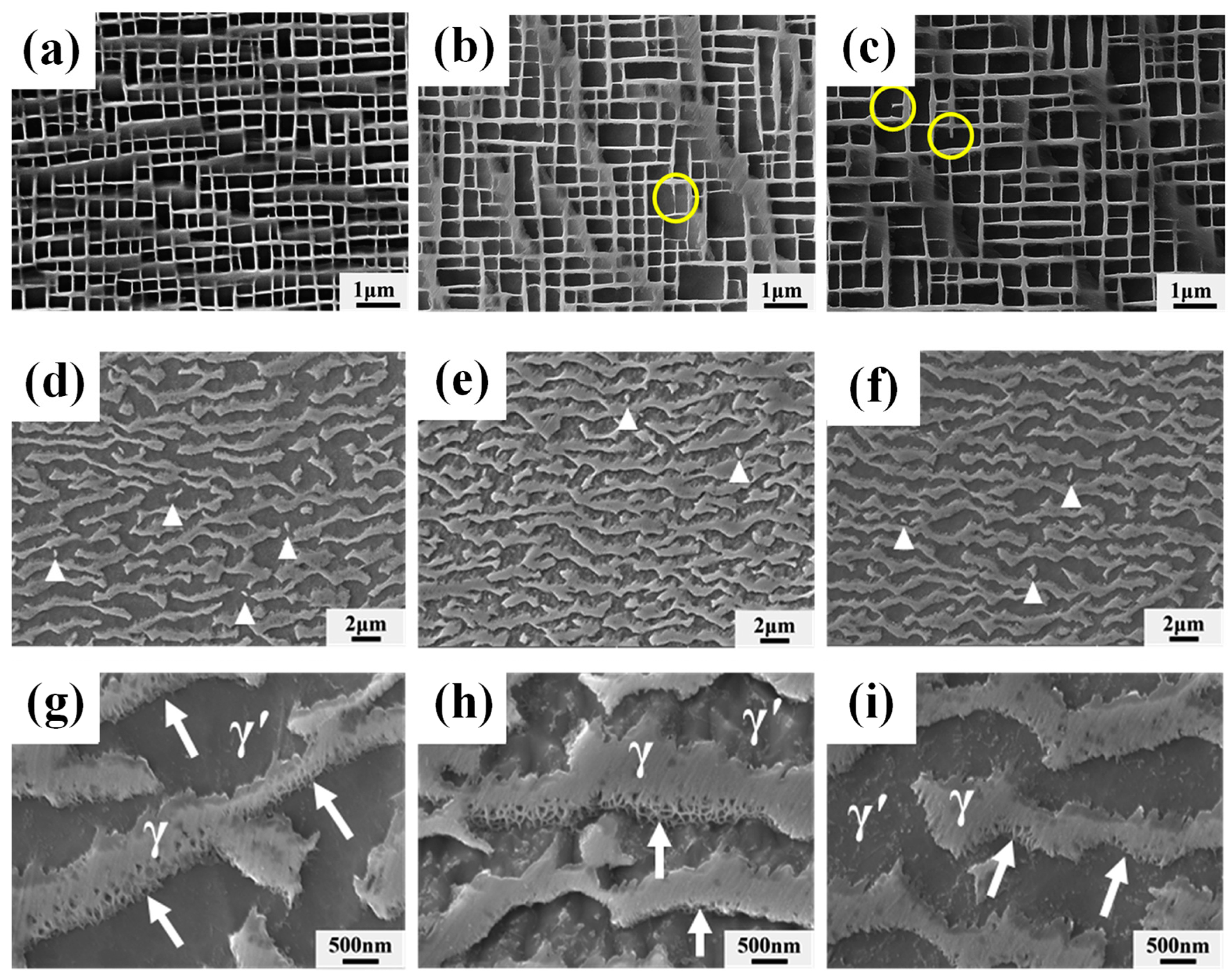
  39. Huang, Y.; Wang, X.; Cui, C.; Li, J.; Ye, L.; Hou, G.; Yang, Y.; Liu, J.; Zhou, Y.; Sun, X. The effect of coarsening of γ′ precipitate on creep properties of Ni-based single crystal superalloys during long-term aging. Mater. Sci. Eng. A 2020, 773, 138886. [Google Scholar] [CrossRef]
  40. Padture, N.P. Thermal barrier coatings for gas-turbine engine applications. Science 2002, 296, 280–284. [Google Scholar] [CrossRef]
  41. Stott, F.; Wood, G. Growth and adhesion of oxide scales on Al2O3-forming alloys and coatings. Mater. Sci. Eng. 1987, 87, 267–274. [Google Scholar] [CrossRef]
  42. Stern, K.H. Metallurgical and Ceramic Protective Coatings; Springer Science & Business Media: New York, NY, USA, 1996. [Google Scholar]
  43. Jones, R. Thermal Barrier Coatings, Metallurgical and Ceramic Protective Coatings; Springer: Berlin/Heidelberg, Germany, 1996; pp. 194–235. [Google Scholar]
  44. Hasselman, D.; Johnson, L.F.; Bentsen, L.D.; Syed, R.; Lee, H.; Swain, M.V. Thermal diffusivity and conductivity of dense polycrystalline Zr02 ceramics: A survey. Am. Ceram. Soc. Bull. 1987, 66, 799–806. [Google Scholar]
  45. Wang, L.; Wang, Y.; Sun, X.; He, J.; Pan, Z.; Zhou, Y.; Wu, P. Influence of pores on the thermal insulation behavior of thermal barrier coatings prepared by atmospheric plasma spray. Mater. Des. 2011, 32, 36–47. [Google Scholar] [CrossRef]
  46. Johnson, C.; Ruud, J.; Bruce, R.; Wortman, D. Relationships between residual stress, microstructure and mechanical properties of electron beam–physical vapor deposition thermal barrier coatings. Surf. Coat. Technol. 1998, 108, 80–85. [Google Scholar] [CrossRef]
  47. Naeem, M.; Singh, R.; Probert, D. Implications of engine deterioration for a high-pressure turbine-blade’s low-cycle fatigue (LCF) life-consumption. Int. J. Fatigue 1999, 21, 831–847. [Google Scholar] [CrossRef]
  48. American Airlines Aircraft Operating Statistics-Actuals. 2018. Available online: http://web.mit.edu/airlinedata/www/2019%2012%20Month%20Documents/Aircraft%20and%20Related/Carrier%20Operating%20Stats/American%20Airlines%20Aircraft%20Operating%20Statistics-%20Actuals.html (accessed on 13 September 2020).
  49. Segersäll, M.; Moverare, J.J. Crystallographic orientation influence on the serrated yielding behavior of a single-crystal superalloy. Materials 2013, 6, 437–444. [Google Scholar] [CrossRef] [Green Version]
  50. Liu, L.; Meng, J.; Liu, J.; Jin, T.; Sun, X.; Zhang, H. Effects of crystal orientations on the cyclic deformation behavior in the low cycle fatigue of a single crystal nickel-base superalloy. Mater. Des. 2017, 131, 441–449. [Google Scholar] [CrossRef]
  51. Fleury, E.; Rémy, L. Low cycle fatigue damage in nickel-base superalloy single crystals at elevated temperature. Mater. Sci. Eng. A 1993, 167, 23–30. [Google Scholar] [CrossRef]
  52. Li, Y.; Wu, X.; Yu, H.; Su, B.; Zhang, M. Low cyclic deformation behavior of single crystal nickel base superalloys with different orientations at 980 °C. Chin. Electron Microsc. Soc. 2014, 33, 15–18. [Google Scholar]
  53. Yu, J.; Sun, X.; Jin, T.; Zhao, N.; Guan, H.; Hu, Z. High temperature creep and low cycle fatigue of a nickel-base superalloy. Mater. Sci. Eng. A 2010, 527, 2379–2389. [Google Scholar] [CrossRef]
  54. Zhang, L.; Zhao, L.; Roy, A.; Silberschmidt, V.; McColvin, G. Low-cycle fatigue of single crystal nickel-based superalloy–mechanical testing and TEM characterisation. Mater. Sci. Eng. A 2019, 744, 538–547. [Google Scholar] [CrossRef]
  55. Belyaev, M.S.; Morozova, L.V.; Gorbovets, M.A.; Slavin, A.V. High-cycle fatigue of single-crystal heat-resistant nickel alloy under the conditions of stress concentration. Metallurgist 2020, 63, 1–11. [Google Scholar] [CrossRef]
  56. Cervellon, A.; Hémery, S.; Kürnsteiner, P.; Gault, B.; Kontis, P.; Cormier, J. Crack initiation mechanisms during very high cycle fatigue of Ni-based single crystal superalloys at high temperature. Acta Mater. 2020, 188, 131–144. [Google Scholar] [CrossRef]
  57. Sabnis, P.A.; Forest, S.; Arakere, N.K.; Yastrebov, V.A. Crystal plasticity analysis of cylindrical indentation on a Ni-base single crystal superalloy. Int. J. Plast. 2013, 51, 200–217. [Google Scholar] [CrossRef]
  58. Murthy, H.; Gao, G.; Farris, T.N. Fretting fatigue of single crystal nickel at 600 °C. Tribol. Int. 2006, 39, 1227–1240. [Google Scholar] [CrossRef]
  59. Matlik, J.; Farris, T.; Haake, F.; Swanson, G.; Duke, G. High-frequency, high-temperature fretting-fatigue experiments. Wear 2006, 261, 1367–1382. [Google Scholar] [CrossRef]
  60. Rengaraj, B.; Baba, S.; Okazaki, M. Influence of crystal orientation on cyclic sliding friction and fretting fatigue behavior of single crystal Ni-base superalloys. In Superalloys 2016, Proceedings of the 13th Intenational Symposium of Superalloys, Seven Springs, PA, USA, 11–15 September 2016; Wiley Online Library: Hoboken, NJ, USA, 2016; pp. 395–404. [Google Scholar]
  61. Su, Y.; Han, Q.-N.; Zhang, C.-C.; Shi, H.-J.; Niu, L.-S.; Deng, G.-J.; Rui, S.-S. Effects of secondary orientation and temperature on the fretting fatigue behaviors of Ni-based single crystal superalloys. Tribol. Int. 2019, 130, 9–18. [Google Scholar] [CrossRef]
  62. Han, Q.-N.; Qiu, W.; Shang, Y.-B.; Shi, H.-J. In-situ SEM observation and crystal plasticity finite element simulation of fretting fatigue crack formation in Ni-base single-crystal superalloys. Tribol. Int. 2016, 101, 33–42. [Google Scholar] [CrossRef]
  63. De Pannemaecker, A.; Buffiere, J.; Fouvry, S.; Graton, O. In situ fretting fatigue crack propagation analysis using synchrotron X-ray radiography. Int. J. Fatigue 2017, 97, 56–69. [Google Scholar] [CrossRef]
  64. Su, Y.; Han, Q.-N.; Qiu, W.; He, Z.; Shang, Y.-B.; Shi, H.-J.; Niu, L.-S. High temperature in-situ SEM observation and crystal plasticity simulation on fretting fatigue of Ni-based single crystal superalloys. Int. J. Plast. 2020, 127, 102645. [Google Scholar] [CrossRef]
  65. Han, Q.-N.; Qiu, W.; He, Z.; Su, Y.; Ma, X.-F.; Shi, H.-J. The effect of crystal orientation on fretting fatigue crack formation in Ni-based single-crystal superalloys: In-situ SEM observation and crystal plasticity finite element simulation. Tribol. Int. 2018, 125, 209–219. [Google Scholar] [CrossRef]
  66. Buffiere, J.-Y.; Cheynet, M.; Ignat, M. Stem analysis of the local chemical composition in the nickel-based superalloy CMSX-2 after creep at high temperature. Scr. Mater. 1996, 34, 657–671. [Google Scholar] [CrossRef]
  67. Caron, P.; Khan, T. Improvement of creep strength in a nickel-base single-crystal superalloy by heat treatment. Mater. Sci. Eng. 1983, 61, 173–184. [Google Scholar] [CrossRef]
  68. Cormier, J.; Cailletaud, G. Constitutive modeling of the creep behavior of single crystal superalloys under non-isothermal conditions inducing phase transformations. Mater. Sci. Eng. A 2010, 527, 6300–6312. [Google Scholar] [CrossRef]
  69. Ai, C.; Zhao, X.; Zhou, J.; Zhang, H.; Liu, L.; Pei, Y.; Li, S.; Gong, S. Application of a modified Ostwald ripening theory in coarsening of γ′ phases in Ni based single crystal superalloys. J. Alloys Compd. 2015, 632, 558–562. [Google Scholar] [CrossRef]
  70. Nabarro, F.R.N. Rafting in Superalloys. Metall. Mater. Trans. A 1996, 27, 513–530. [Google Scholar] [CrossRef]
  71. Acharya, M.; Fuchs, G. The effect of long-term thermal exposures on the microstructure and properties of CMSX-10 single crystal Ni-base superalloys. Mater. Sci. Eng. A 2004, 381, 143–153. [Google Scholar] [CrossRef]
  72. Zhang, J.X.; Murakumo, T.; Koizumi, Y.; Kobayashi, T.; Harada, H. Slip geometry of dislocations related to cutting of the γ′ phase in a new generation single-crystal superalloy. Acta Mater. 2003, 51, 5073–5081. [Google Scholar] [CrossRef]
  73. Simms, N.; Encinas-Oropesa, A.; Nicholls, J. Hot corrosion of coated and uncoated single crystal gas turbine materials. Mater. Corros. 2008, 59, 476–483. [Google Scholar] [CrossRef]
  74. Montero, X.; Ishida, A.; Meißner, T.; Murakami, H.; Galetz, M. Effect of surface treatment and crystal orientation on hot corrosion of a Ni-based single-crystal superalloy. Corros. Sci. 2020, 166, 108472. [Google Scholar] [CrossRef]
  75. Sims, C.T.; Stoloff, N.S.; Hagel, W.C. Superalloys II; Wiley & Sons: New York, NY, USA, 1987. [Google Scholar]
  76. Nicholls, J.R.; Saunders, S.R.J. Hot-salt corrosion standards, test procedures and performance. High Temp. Technol. 1989, 7, 170. [Google Scholar] [CrossRef]
  77. Schütze, M.; Quadakkers, W.; Nicholls, J.R. Lifetime Modelling of High Temperature Corrosion Processes; European Federation of Corrosion: Brussels, Belgium, 2001. [Google Scholar]
  78. Schumann, E.; Sarioglu, C.; Blachere, J.R.; Pettit, F.S.; Meier, G.H. High-temperature stress measurements during the oxidation of NiAl. Oxid. Met. 2000, 53, 259–272. [Google Scholar] [CrossRef]
  79. Schlichting, K.; Vaidyanathan, K.; Sohn, Y.; Jordan, E.; Gell, M.; Padture, N.P. Application of Cr3+ photoluminescence piezo-spectroscopy to plasma-sprayed thermal barrier coatings for residual stress measurement. Mater. Sci. Eng. A 2000, 291, 68–77. [Google Scholar] [CrossRef]
  80. Mumm, D.R.; Evans, A. On the role of imperfections in the failure of a thermal barrier coating made by electron beam deposition. Acta Mater. 2000, 48, 1815–1827. [Google Scholar] [CrossRef]
  81. Sohn, Y.; Kim, J.; Jordan, E.; Gell, M. Thermal cycling of EB-PVD/MCrAlY thermal barrier coatings: I. Microstructural development and spallation mechanisms. Surf. Coat. Technol. 2001, 146, 70–78. [Google Scholar] [CrossRef]
  82. Gell, M.; Eric, J.; Krishnakumar, V.; McCarron, K.; Barber, B.; Sohn, Y.-H.; Tolpygo, V.K. Bond strength, bond stress and spallation mechanisms of thermal barrier coatings. Surf. Coat. Technol. 1999, 120, 53–60. [Google Scholar] [CrossRef]
  83. Gong, X.-Y.; Clarke, D.R. On the measurement of strain in coatings formed on a wrinkled elastic substrate. Oxid. Met. 1998, 50, 355–376. [Google Scholar] [CrossRef]
  84. Srivastava, R.R.; Kim, M.-S.; Lee, J.-C.; Jha, M.K.; Kim, B.-S. Resource recycling of superalloys and hydrometallurgical challenges. J. Mater. Sci. 2014, 49, 4671–4686. [Google Scholar] [CrossRef]
  85. Srivastava, R.R.; Kim, M.-S.; Lee, J.-C. Novel aqueous processing of the reverted turbine-blade superalloy for rhenium recovery. Ind. Eng. Chem. Res. 2016, 55, 8191–8199. [Google Scholar] [CrossRef]
  86. J.A.D. Corporation. Worldwide Market Forecast 2019–2038. 2019. Available online: http://www.jadc.jp/files/topics/143_ext_01_en_0.pdf (accessed on 22 April 2020).
  87. Rolls-Royce Opens Advanced Turbine Blade Casting Facility. 2015. Available online: https://www.aerospacemanufacturinganddesign.com/article/rolls-royce-turbine-blade-casting-031215/ (accessed on 1 October 2020).
  88. Margolis, N.; Jamison, K.; Dove, L. Energy and Environmental Profile of the US Metal Casting Industry; Energetics, Inc.: Columbia, MD, USA, 1999. [Google Scholar]
  89. Wilson, J.M.; Piya, C.; Shin, Y.C.; Zhao, F.; Ramani, K. Remanufacturing of turbine blades by laser direct deposition with its energy and environmental impact analysis. J. Clean. Prod. 2014, 80, 170–178. [Google Scholar] [CrossRef]
  90. Kuipers, J.; Eng, P. Practical Experience with Full Solution Rejuvenation of Single Crystal Gas Turbine Blades. In Proceedings of the Industrial Application of Gas Turbines Committee Symposium, Banff, AB, Canada, 23–25 October 2017. [Google Scholar]
  91. Basak, A.; Das, S. Epitaxy and microstructure evolution in metal additive manufacturing. Annu. Rev. Mater. Res. 2016, 46, 125–149. [Google Scholar] [CrossRef]
  92. Babu, S.S.; David, S.A.; Park, J.W.; Vitek, J.M. Joining of nickel base superalloy single crystals. Sci. Technol. Weld. Join. 2004, 9, 1–12. [Google Scholar] [CrossRef]
  93. Henderson, M.B.; Arrell, D.; Larsson, R.; Heobel, M.; Marchant, G. Nickel based superalloy welding practices for industrial gas turbine applications. Sci. Technol. Weld. Join. 2004, 9, 13–21. [Google Scholar] [CrossRef]
  94. Ojo, O.; Chaturvedi, M. On the role of liquated γ′ precipitates in weld heat affected zone microfissuring of a nickel-based superalloy. Mater. Sci. Eng. A 2005, 403, 77–86. [Google Scholar] [CrossRef]
  95. Stueber, R.J.; Milidantri, T.; Tadayon, M. Welding High-Strength Nickel Base Superalloys. U.S. Patent 5,312,497, 10 September 1994. [Google Scholar]
  96. Marcin, J.J., Jr.; Neutra, J.A.; Abbott, D.H.; Aduskevich, J.P.; Shah, D.M.; Carraway, D.N.; Langevin, R.P.; Sauerhoefer, M.R.; Stone, R.A. Method of Repairing Metallic Articles by Energy Beam Deposition with Reduced Power Density. U.S. Patent 5,914,059, 22 June 1999. [Google Scholar]
  97. Kathuria, Y. Laser surface cladding: A unique application to the turbine industry. In Laser Assisted Net Shape Engineering, Proceedings of the 30th International CIRP Seminar on Manufacturing Systems—LANE ’97, Erlangen, Germany, 23–26 September 1997; Meisenbach: Berlin, Germany, 1997; pp. 23–26. [Google Scholar]
  98. Kreutz, E. Pulsed laser deposition of ceramics-fundamentals and applications. Appl. Surf. Sci. 1998, 127, 606–613. [Google Scholar] [CrossRef]
  99. Mah, R. Directed light fabrication. Adv. Mater. Process. 1997, 151, 477144. [Google Scholar]
  100. Basak, A.; Raghu, S.H.; Das, S. Microstructures and microhardness properties of CMSX-4® additively fabricated through scanning laser epitaxy (SLE). J. Mater. Eng. Perform. 2017, 26. [Google Scholar] [CrossRef]
  101. Gotterbarm, M.R.; Rausch, A.M.; Körner, C. Fabrication of single crystals through a µ-helix grain selection process during electron beam metal additive manufacturing. Metals 2020, 10, 313. [Google Scholar] [CrossRef] [Green Version]
  102. Gäumann, M.; Henry, S.; Cléton, F.; Wagnière, J.-D.; Kurz, W. Epitaxial laser metal forming: Analysis of microstructure formation. Mater. Sci. Eng. A 1999, 271, 232–241. [Google Scholar] [CrossRef]
  103. Murr, L.E.; Martinez, E.; Pan, X.; Gaytan, S.; Castro, J.; Terrazas, C.; Medina, F.; Wicker, R.; Abbott, D. Microstructures of Rene 142 nickel-based superalloy fabricated by electron beam melting. Acta Mater. 2013, 61, 4289–4296. [Google Scholar] [CrossRef]
  104. Ramsperger, M.; Singer, R.F.; Körner, C. Microstructure of the nickel-base superalloy CMSX-4 fabricated by selective electron beam melting. Metall. Mater. Trans. A 2016, 47, 1469–1480. [Google Scholar] [CrossRef] [Green Version]
  105. Basak, A.; Acharya, R.; Das, S. Additive manufacturing of single-crystal superalloy CMSX-4 through scanning laser epitaxy: Computational modeling, experimental process development, and process parameter optimization. Metall. Mater. Trans. A 2016, 47, 3845–3859. [Google Scholar] [CrossRef]
  106. Acharya, R.; Bansal, R.; Gambone, J.J.; Das, S. A coupled thermal, fluid flow, and solidification model for the processing of single-crystal alloy CMSX-4 through scanning laser epitaxy for turbine engine hot-section component repair (part I). Metall. Mater. Trans. A 2014, 45, 2247–2261. [Google Scholar] [CrossRef]
  107. Basak, A.; Yang, Y.; Das, S. On the spatial variation of the microstructure and microhardness properties of nickel-based superalloy René 142 fabricated via scanning laser epitaxy (SLE). Mater. Perform. Charact. 2019, 8, 1237–1248. [Google Scholar] [CrossRef]
  108. Basak, A.; Das, S. Carbide Formation in Additive Manufacturing of Single-Crystal Superalloy René N5 Processed Through Scanning Laser Epitaxy. In Proceedings of the Materials Science and Technology Conference, Salt Lake City, UT, USA, 23–27 October 2016; pp. 51–58. [Google Scholar]
  109. Basak, A.; Das, S. Additive manufacturing of nickel-base superalloy René N5 through scanning laser epitaxy (SLE)−Material processing, microstructures, and microhardness properties. Adv. Eng. Mater. 2017, 19, 1–10. [Google Scholar] [CrossRef]
  110. Wang, L.; Wang, N. Effect of substrate orientation on the formation of equiaxed stray grains in laser surface remelted single crystal superalloys: Experimental investigation. Acta Mater. 2016, 104, 250–258. [Google Scholar] [CrossRef]
  111. Liu, W.; Dupont, J.N. Direct laser deposition of a single-crystal Ni3Al-based IC221W alloy. Metall. Mater. Trans. A 2005, 36, 3397–3406. [Google Scholar] [CrossRef]
  112. Santos, E.C.; Kida, K.; Carroll, P.; Vilar, R. Optimization of laser deposited Ni-based single crystal superalloys microstructure. Adv. Mater. Res. 2011, 154, 1405–1414. [Google Scholar] [CrossRef]
  113. Liang, Y.-J.; Cheng, X.; Wang, H.-M.; Li, J. Microstructural control during laser additive manufacturing of single-crystal nickel-base superalloys: New processing–microstructure maps involving powder feeding. Mater. Des. 2017, 130, 197–207. [Google Scholar] [CrossRef]
  114. Vilar, R.; Almeida, A. Repair and manufacturing of single crystal Ni-based superalloys components by laser powder deposition—A review. J. Laser Appl. 2015, 27, 17004. [Google Scholar] [CrossRef]
  115. Ci, S.; Liang, J.; Li, J.; Zhou, Y.; Sun, X. Microstructure and tensile properties of DD32 single crystal Ni-base superalloy repaired by laser metal forming. J. Mater. Sci. Technol. 2020, 45, 23–34. [Google Scholar] [CrossRef]
  116. Hedges, M.; Calder, N. Near Net Shape Rapid Manufacture & Repair by LENS, Cost Effective Manufacture via Net-Shape Processing; Neotech Services MTP: Nuremberg, Germany, 2006. [Google Scholar]
  117. Wahl, J.B.; Harris, K. Improved 3rd generation single crystal superalloy CMSX-4® Plus (SLS)–A study of evolutionary alloy development. Sueperalloys 2004, 2004, 45–52. [Google Scholar]
  118. Allison, J.; Backman, D.; Christodoulou, L. Integrated computational materials engineering: A new paradigm for the global materials profession. JOM 2006, 58, 25–27. [Google Scholar] [CrossRef]
  119. Engeli, R.; Etter, T.; Hövel, S.; Wegener, K. Processability of different IN738LC powder batches by selective laser melting. J. Mater. Process. Technol. 2016, 229, 484–491. [Google Scholar] [CrossRef]
  120. Averyanova, M.; Cicala, E.; Bertrand, P.; Grevey, D.; Bertrand, P. Experimental design approach to optimize selective laser melting of martensitic 17-4 PH powder: Part I–single laser tracks and first layer. Rapid Prototyp. J. 2012, 18, 28–37. [Google Scholar] [CrossRef]
  121. King, W.E.; Barth, H.D.; Castillo, V.M.; Gallegos, G.F.; Gibbs, J.W.; Hahn, D.E.; Kamath, C.; Rubenchik, A.M. Observation of keyhole-mode laser melting in laser powder-bed fusion additive manufacturing. J. Mater. Process. Technol. 2014, 214, 2915–2925. [Google Scholar] [CrossRef]
  122. Tapia, G.; Khairallah, S.; Matthews, M.; King, W.E.; Elwany, A. Gaussian process-based surrogate modeling framework for process planning in laser powder-bed fusion additive manufacturing of 316L stainless steel. Int. J. Adv. Manuf. Technol. 2018, 94, 3591–3603. [Google Scholar] [CrossRef]
  123. Strano, G.; Hao, L.; Everson, R.M.; Evans, K.E. Surface roughness analysis, modelling and prediction in selective laser melting. J. Mater. Process. Technol. 2013, 213, 589–597. [Google Scholar] [CrossRef]
  124. Song, Y.; Kube, C.M.; Zhang, J.; Li, X. Higher-order spatial correlation coefficients of ultrasonic backscattering signals using partial cross-correlation analysis. J. Acoust. Soc. Am. 2020, 147, 757–768. [Google Scholar] [CrossRef]
  125. Smith, R.J.; Hirsch, M.; Patel, R.; Li, W.; Clare, A.T.; Sharples, S.D. Spatially resolved acoustic spectroscopy for selective laser melting. J. Mater. Process. Technol. 2016, 236, 93–102. [Google Scholar] [CrossRef]
Figure 1. A representative schematic showing the cooling mechanisms in a turbine blade (Reproduced from [3] under the terms of the Creative Commons Attribution 3.0 License from http://creativecommons.org/licenses/by/3.0/).
Jmmp 04 00101 g001
Figure 2. Representative images showing the (a) equiaxed, (b) directionally solidified, (c) single crystal microstructure. (d) Zoomed view of (c) illustrating the dendrite microstructure in single crystal turbine blades (Reproduced with permission from [5], Copyright 2008 by The Minerals, Metals and Materials Society).
Jmmp 04 00101 g002
Figure 3. (a) Turbine airfoil with worn-out blade tip, (b) cracking in the platform section, (c) tear in turbine blade (Reproduced from [9] under the terms of the Creative Commons Attribution 4.0 License from http://creativecommons.org/licenses/by/4.0/), and (d) cracked turbine blades (Reproduced from [9] under the terms of the Creative Commons Attribution 4.0 License from http://creativecommons.org/licenses/by/4.0/).
Jmmp 04 00101 g003
Figure 4. (a) Microstructure of SX René N5 showing the formation of carbide precipitates. (b) A representative image showing the formation of γ/ γ′ microstructure in SX René N5.
Jmmp 04 00101 g004
Figure 5. (a) Circular-clustered wax assembly (Reproduced from [21] under the terms of the Creative Commons Attribution 4.0 License from http://creativecommons.org/licenses/by/4.0/); (b) schematic of a pigtail demonstrating how the turns in the block selector function to cull unwanted crystal orientations until only one orientation remains (Reproduced with permission from [24]); (c) the shell mold corresponding to a wax assembly in (a) for casting SX blades (Reproduced from [21] under the terms of the Creative Commons Attribution 4.0 License from http://creativecommons.org/licenses/by/4.0/); and (d) Cross-section of a ready-to-use mold demonstrating the pin placement used to stabilize the ceramic cores and the ceramic mold (Reproduced from [26] under the terms of the Creative Commons Attribution 4.0 License from http://creativecommons.org/licenses/by/4.0/).
Jmmp 04 00101 g005
Figure 6. (a) A representative vacuum Bridgman furnace showing the radiation baffle separating the heating and cooling zone. In this furnace, radiation heating affects the casting the most because it is the dominant form of heating (Adapted from [31]). (b) Schematic of the liquid metal cooling-assisted casting (LMC) (Adapted from [21]). (c) Schematic of the gas cooling casting (GCC) process (Adapted from [21]).
Jmmp 04 00101 g006
Figure 7. Schematic of the coating structure in the SX turbine blades (Adapted from [40]).
Jmmp 04 00101 g007
Figure 8. Scanning electron microscopy (SEM) images of microstructures after aging at 1000 °C for (a) 100 h, (b) 500 h, and (c) 1000 h. SEM images of microstructures aged at 1000 °C for (d,g) 100 h, (e,h) 500 h, and (f,i) 1000 h ruptured following creep deformation while subjected to 1140 °C/137 MPa: (df) the γ/γ′ microstructure and (gi) representative interfacial dislocation networks. Figure (a) through (i) are reproduced with permission from [39].
Jmmp 04 00101 g008
Figure 9. (a) Material and energy required per year to produce SX blades, (b) material loss for three different scenarios, and (c) energy loss for three different scenarios.
Jmmp 04 00101 g009aJmmp 04 00101 g009b
Figure 10. Classification of AM processes. Green boxes represent the AM processes that have shown success in repairing simple geometry SX components to date.
Jmmp 04 00101 g010
Figure 11. Representative optical images showing the capability of different AM processes in repairing a candidate SX alloy, CMSX-4®—(a) laser powder bed fusion (PBF) (L-PBF) (Reproduced with permission from [100]), (b) E-PBF (Reproduced from [101] under the terms of the Creative Commons Attribution 4.0 License from http://creativecommons.org/licenses/by/4.0/), and (c) laser-based DED (L-DED) (Reproduced with permission from [102]). Electron backscatter diffraction (EBSD) refers to electron backscatter diffraction.
Jmmp 04 00101 g011
Table 1. Composition (wt.%) of a few popular nickel-base superalloys that are cast with SX microstructure (Obtained from [15]).
CCrNiCoMoWNb/CbTaTiAlBZrHfRe
PWA 1480 10Bal5 4 121.550.003
PWA 1484 5Bal101.95.9 8.7 5.65 0.13
PWA 1487 5Bal101.95.9 8.4 5.65 0.253
René N4 10Bal8260.553.54.2 0.2
René N5 7Bal825 6 6.2 0.23
René N6 4Bal1216 7 5.8 0.25
CM 186 LC0.076Bal90.58 30.75.70.0150.0051.43
CMSX-2 8Bal50.68 615.6
CMSX-3 8Bal50.68 615.6 0.1
CMSX-4 6.5Bal90.66 6.515.6 0.13
CMSX-6 10Bal53 24.74.8 0.1
CMSX-10K 2Bal30.450.180.25.7 0.036
CMSX-10N 1.5Bal30.450.0580.15.8 0.037
CMSX 4860.075Bal90.79 4.50.75.70.0150.00513
SRR 99 8Bal5 10 32.25.5
RR 2000 10Bal153 45.5
AM 1 8Bal626 91.25.2
AM 3 8Bal625 426
SC 180 5Bal1025 8.515.2 0.13
MC-2 8Bal528 61.55
C = carbon, Cr = chromium, Co = cobalt, Mo = molybdenum, W = tungsten, Nb/Cb = niobium, Ta = tantalum, Ti = titanium, Al = aluminum, B = boron, Zr = zirconium, Hf = hafnium, Re = rhenium.
Publisher’s Note: MDPI stays neutral with regard to jurisdictional claims in published maps and institutional affiliations.

