Review

A Review on Strain Gradient Plasticity Approaches in Simulation of Manufacturing Processes

by
Raffaele Russo
1,2,*,
Franck Andrés Girot Mata
1,3,
Samuel Forest
2 and
Dimitri Jacquin
4
1
Department of Mechanical Engineering, Faculty of Engineering, University of the Basque Country, 48013 Bilbao, Spain
2
MINES ParisTech, PSL University, Centre des Matériaux, CNRS UMR 7633, BP 87, 91003 Evry, France
3
IBERBASQUE, Basque Foundation for Science, 48009 Bilbao, Spain
4
Institut de Mécanique et d’Ingénierie (I2M), University of Bordeaux, UMR 5295, CNRS, F-33400 Talence, France
*
Author to whom correspondence should be addressed.
J. Manuf. Mater. Process. 2020, 4(3), 87; https://doi.org/10.3390/jmmp4030087
Submission received: 25 June 2020 / Revised: 27 August 2020 / Accepted: 28 August 2020 / Published: 3 September 2020
(This article belongs to the Special Issue Optimization and Simulation of Solid State Manufacturing Processes)

Abstract

:
Predicting the performances of a manufactured part is extremely important, especially for industries in which there is almost no room for uncertainties, such as aeronautical or automotive. Simulations performed by means of numerical methods such as Finite Element Methods represent a powerful instrument in achieving high level of predictability. However, some particular combinations of manufactured materials and manufacturing processes might lead to unfavorable conditions in which the classical mathematical models used to predict the behavior of the continuum are not anymore able to deliver predictions that are in good agreement with experimental evidence. Since the first evidences of the shortcomings of the classical model were highlighted, many non-classical continuum mechanics theories have been developed, and most of them introduce dependencies at different levels with the Plastic Strain Gradient. This manuscript aims at gathering the milestone contributions among the Strain Gradient Plasticity Theories developed so far, with the object of exploring the way they interface with the requirements posed by the challenges in simulating manufacturing operations. Finally, the most relevant examples of the applications of Strain Gradient Plasticity Theories for manufacturing simulations have been reported from literature.

1. Introduction

The topic of Strain Gradient Theories (SGT) experienced a fervent increase of interest from the scientific community in recent years. Although multiple reasons made the SGT one of the hot topics in the field of Continuum Mechanics (CM), the main causes can be identified in the ever-increasing computational power of numerical calculators (thus enabling the implementation of techniques beforehand impossible to use) and in the demand of more sophisticated CM theories which would better predict the medium behavior under specific material deformation conditions. SGTs could be employed whenever the Classical CM framework is not delivering anymore a proper medium behavior description if compared with experimental observations. The features embodied in the SGTs can be of crucial importance in several situations, and in this manuscript we assess the role that they might play for manufacturing process simulations. However, it must be noted that the adoption of such theories increases the computational cost involved in simulating the observed phenomenon.
The most general feature, shared by all the SGTs, is the introduction of one or more scale lengths in the model used to describe the medium behavior. This is done through the definition of additional deformation measures that are meant to capture specific phenomena which cannot be predicted by the classical CM models. In the vast majority of the cases, the magnitude and the influence of these additional deformation measures are negligible if compared with the standard one, i.e., strain. In specific situations, however, the material behavior demonstrates noticeable susceptibility to these supplementary deformation measures, and proper models are required to capture such behaviors through simulations. The gradient of the strain has been widely and unanimously recognized as one of the main feature which needs to be incorporated in the Classical CM theory to predict such behaviors. Among all the SGTs, those that make use of the gradient of the plastic part of the strain are called Strain Gradient Plasticity Theories (SGPT).
Experimental observations show that many metal manufacturing processes are affected by these phenomena, demonstrating noticeable sensitivity toward non-conventional deformation measures [1,2,3,4,5,6,7,8,9,10,11]. The manufacturing techniques in which the strain gradient plays a bigger role result to be those in which the loads are highly localized, e.g., micro-cutting, milling, micro-bending, thin wire drawing, machining, Friction Stir Welding (FSW), sheet stamping, inverse drawing, adiabatic cutting. These machining processes favor the development of rather peculiar conditions in the processed material, where a combination of separate factors contribute to produce a relatively complex scenario.
The present research aims at addressing the following research question: What is the state of the art in using enhanced continuum mechanics and, more specifically, SGPTs, to simulate manufacturing simulations. This research question can be broken down in the following sub-questions:
  • What is an enhanced continuum mechanics model?
  • Why such models are required for the simulation of manufacturing operations?
  • Which enhanced models of continuum mechanics can be used to simulate manufacturing operations?
  • Which contributions can be found in literature that already used enhanced model to simulate manufacturing operations?
In Section 2, this multitude of events simultaneously taking place during these processes are singularly assessed, and then the features that represent them are traduced into requirements of a continuum mechanics theory meant to correctly describe them. Section 3 presents the milestones in the development of different SGPTs and in Section 4 the investigations that employed the SGPTs to simulate machining operations will be thoroughly reviewed. Finally, the conclusions of the present review manuscript will present advantages and disadvantages of using different SGPTs to simulate different machining processes.

2. Challenges in Manufacturing Processes Simulations

Among the different metal manufacturing techniques, the ones that require a proper theory to be described are those that modify the material through strain localization, or severe plastic strain development or material removal, or a combination of those. During machining, for example, material is removed from the work piece by inducing large amounts of shear in localized areas called Shear Bands (SBs) (see Figure 1). Due to the high speed of the process (cutting velocities up to 90 m/s) [12,13,14,15], high strain rates ( 10 5 s 1 ) are induced in the SBs [16,17,18]. The high levels of stresses and strains give rise to plastic deformations, therefore inducing softening in the material at this same location. In addition to this, since the SBs usually span an extremely narrow area if compared to the global scale of the work piece, the continuum at this location experiences high stress and high strain gradients as well. To complete the picture, it must be mentioned that plastic deformations usually give rise to heat productions, and considering the case in which the rate of heat production is much larger than the heat flow within the material (especially in metals characterized by low thermal conductivity), high temperature fields are retained, and the SBs are referred to as Adiabatic Shear Bands (ASBs). In Figure 2, the crystallographic analysis during a FSW process highlights the modification of the grain size and orientation induced during manufacturing. Shear bands have been reported to appear also during a high-temperature compression test on Nickel super-alloy [15].
On top of the already complex scenario, at the location where the applied forces are transferred from the tool to the workpiece, the material experiences complex behaviors as well. High stress and shear gradients develop in this zone, leading to the same conditions which are found within the SB. Furthermore, the mechanism with which the loads are transferred from the workpiece to the material must be accurately assessed as well. The extreme conditions in which the contact must be modeled are actually different from the ones for which the classical contact models have been developed.
Overall, the problem of simulating machining seems to be composed of several sub-problems, some of them interconnected with each others, and some independent from one another. This complex problem can be more easily assessed if divided into separate and independent blocks. These might be listed as:
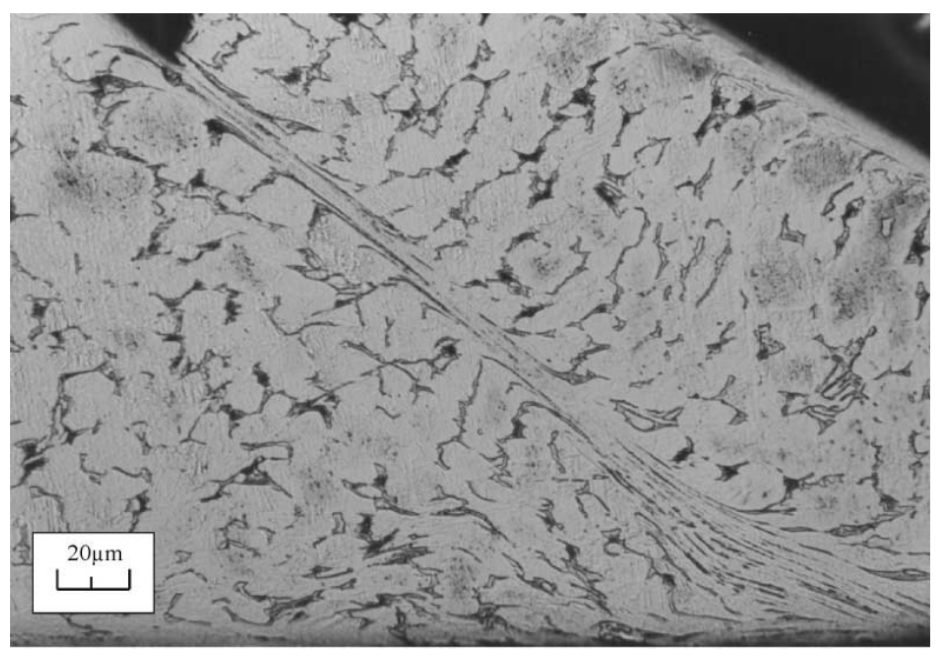
  • Strain localization in a length scale whose order of magnitude is the same as grain size, therefore violating the limit of validity of material homogeneity;
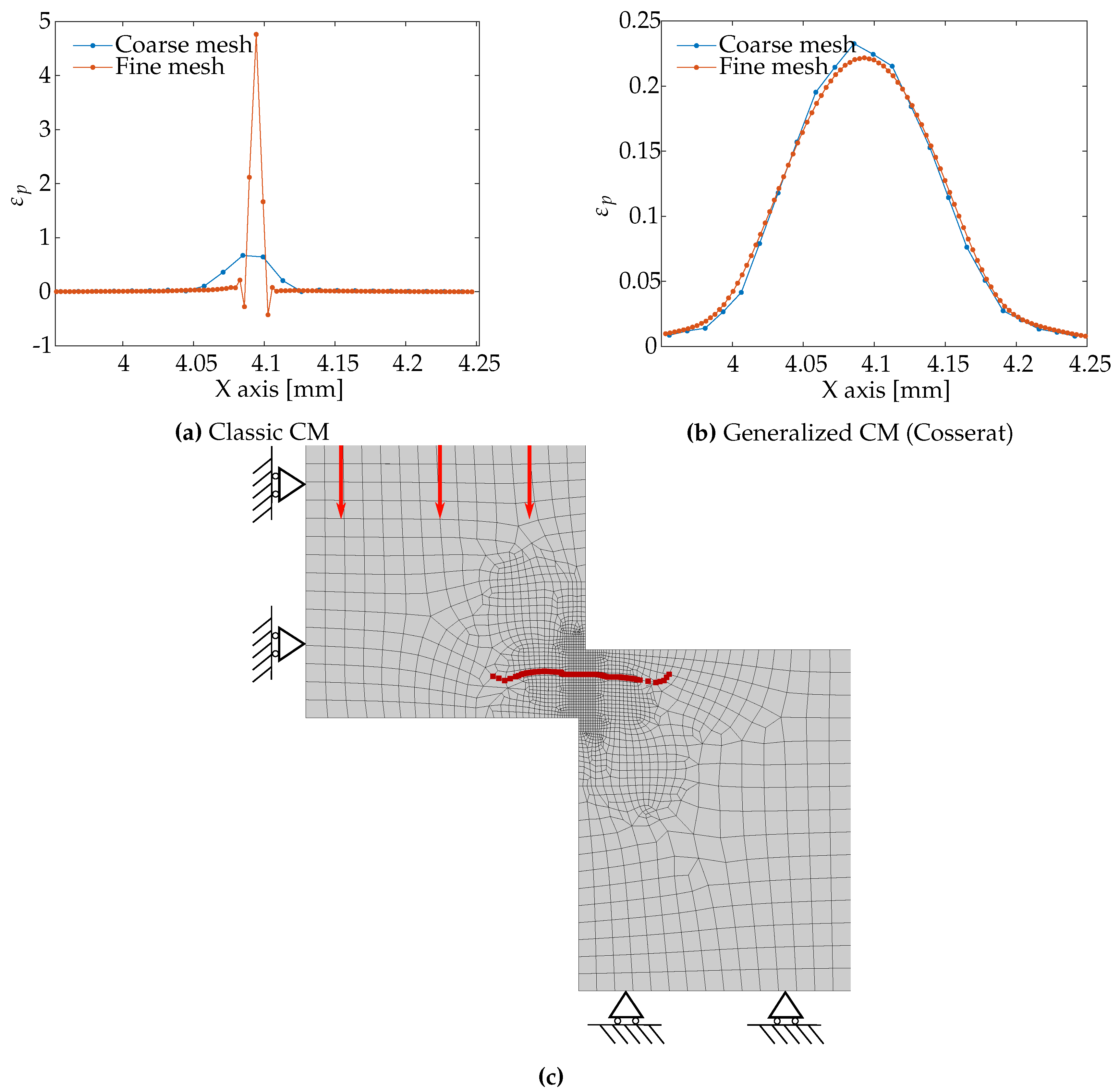
  • Mesh-size hypersensitivity when introducing material softening in the behavior law during the analysis;
  • Proper material characterization at high temperatures and high strain rates developing during manufacturing processes;
  • The complex material behavior at the tool-workpiece contact location.
These phenomena could take place separately or simultaneously. Several approaches can be found in literature that address these problems individually, but their occurrence, taking place all at once, represents a challenging issue to be addressed. Complex problems, such as the one investigated here, have also addressed through model reduction methods [19].

2.1. Strain Localization and Mesh-Size Dependency

Strain localization in a narrow area whose order of magnitude is comparable to the material grain size compels the adoption of a non-classical CM framework that would be able to model the size effect. In literature, several authors highlighted the inadequacy of the classical CM framework whenever it was used to reproduce experimental data in which the size effects were noticeable [20,21,22,23,24,25,26,27,28,29,30,31,32,33,34,35,36]. Overall, the inconsistencies are more pronounced whenever the dimensions of the specimens become comparable to the order of magnitude of the specimen grain size, or, equivalently, when the deformations localize in areas whose size is comparable to the specimen grain size.
Fleck and Hutchinson performed several static torsion and tensile tests on copper wires of different diameters (12–170 μ m) [20]. Their results, reported in Figure 3, highlight that smaller diameter wires are characterized by a much stiffer torsional response (scaled with the wire radius), although tensile tests performed on the same specimen demonstrate a very small, thus negligible, size dependency. Similar tests were performed by Liu et al. who reached the same conclusion [37,38]. Fleck and Hutchinson also reported that the size-effect is present in a Vickers micro-indentation test conducted on single crystal tungsten specimens [20]. The performed tests demonstrated a strong size-dependency, as the material hardness doubles by using an indent whose diagonal is one order of magnitude smaller. Similar size-effects in a micro-indentation test have also been reported by many other authors [23,24,25,26,27].
The size-effect has also been experimentally investigated by Stölken and Evans [21]. They presented the results of micro-bending tests conducted on 12.5 μ m, 25 μ m and 50 μ m thin Nickel foils (Figure 4). The results of their tests highlighted that foils with a smaller thickness were behaving stronger. The applied bending moment (normalized with respect to the foil thickness) of the 50 μ m thick foil is twice the one recorded with a 12.5 μ m thick foil. Similar tests leading to similar conclusions were conducted by Ehrler et al. [39].
In the same referenced papers, so as in a broad branch of literature [28,29,30,31,32,33,34,35,36], the authors point out that the classical CM is not able to capture these localization phenomena due to the absence of a length scale in the model that would counteract the localization of the fields. Micro-torsion tests also highlighted the shortcoming of the classical CM framework [40,41]. The SGPT, whose mathematical description includes one or more length scales, has been proposed as a valid candidate to capture phenomena of different natures.
The size-effect can be predicted thanks to the definition of an additional deformation measure, i.e., the strain gradient. The dimensional analysis of this quantity reveals that it is not dimensionless and, unlike strain, it should be adimensionalized by means of a specific length, and the sensitivity of non-classical CM theories to size-effects comes directly from the definition of this non-dimensionless deformation measure. Many researchers investigated over the physical nature of the length scales of the SGPTs. Depending on the degrees of complexity of the observed phenomena, more than one characteristic lengths can be identified. For example, Fleck and Hutchinson identified up to five distinct characteristic lengths, each associated to one of the five invariants of the strain gradient tensor [20]. These characteristic lengths however can be reduced to three in case of incompressible isotropic medium. In a successive study, Fleck and Hutchinson identified a single characteristic length in an equivalent plastic strain gradient theory [42]. Liu and Dunstan, based on the SGPT of Fleck and Hutchinson, gave a physical interpretation to the characteristic length by making a connection to physical quantities via critical thickness theory [33]. Duan et al., based on the same SGPT, associated the additional characteristic length to geometrically necessary dislocations through three different dislocation models [35]. Similarly, Dahlberg and Boåsen assumed an equivalence between the microstructural length scale and dislocation density and provided an evolution law of the characteristic length [43]. Zhang and Aifantis gave a comprehensive review of the interpretations of the characteristic length associated with SGPTs [44].
Several other researchers focused on the calibration procedure and the quantification of this length for metals. Yuan and Chen proposed to identify the characteristic length from micro- and nano- indentation tests [45]. Stölken and Evans developed a micro-bending test to measure the characteristic length [21]. Abu Al-Rub and Voyiadjis also proposed to adopt micro- and nano- indentation tests to calibrate the characteristic length and its evolution law [34,46].
Thereby, it can be concluded that the problem of properly capturing the size-effect rising during manufacturing simulation due to strain localization can be solved by adopting a medium description that includes the gradient of the strain as a deformation measure. In addition, adding the strain gradient as a deformation measure would solve not only the problem related to size-effect, but also the one related to mesh hypersensitivity.
Mesh hypersensitivity is an issue which has its root in the loss of ellipticity of the partial differential equation governing the medium equilibrium [47,48,49]. In case the non-linear plastic behavior of the material experiences a decreasing flow stress, i.e., softening, the nature of the set of partial differential equations governing the equilibrium changes, and a strong mesh sensitivity is experienced, in particular, the solution does not appear to converge toward an asymptotic value when the mesh size is decreased. The process of recovering the property of mesh independence in literature is referred to as regularization procedure.
Jirasek and Rolshoven provided an extensive comparison of the regularization properties of many SGPT by analyzing the response of a mono-dimensional bar under tension, whose plastic behavior is characterized purely by softening [50]. They explored the regularization mechanics of the Toupin-Mindlin elastic SGT [51,52], the plastic version of Toupin-Mindlin SGT developed by Chambon et al. [53], the Fleck and Hutchinson plastic SGT [20] and the Mechanism-based SGT [54]. Nguyen et al. coupled a non-local plasticity model with damage to successfully capture the softening behavior experienced by the material during ductile failure in the post-peak regime [55]. Lele and Anand demonstrated that SGPTs are able to provide mesh independent results in case of viscoplastic material as well [56].
Several other researchers overcame the mesh hypersensitivity issue through other solutions besides the SGT. Mediavilla et al. used a damage-enriched material model, in which the gradient of the damage field would enter in the material model, thereby achieving the same regularization effect produced by the SGTs [57]. Many other researchers included the gradient of the damage variable in the model to regularize the solution [55,58,59,60]. Higher Order continuum descriptions (see Section 3) are also well known equivalent solution to avoid the pathological mesh dependence [61,62,63,64]. In Figure 5, proof of the regularization property of a Higher Order theory (Cosserat medium) is reported. A special combination of specimen geometry and applied boundary conditions induce the appearance of SBs inside the material [65], and it has been demonstrated that the localization of the equivalent plastic strain inside the SB is mesh-independent in case a Generalized CM (Cosserat) theory is used.
Therefore, the issues of mesh hypersensitivity due to localization during machining simulations can be simultaneously addressed through the adoption of non-local theories, to which the SGPT belong.

2.2. Material Characterization at High Temperatures and High Strain Rates

The high strain rate fields produced during machining are inevitably intertwined with thermal-related consequences. Materials experiencing high strain rate are likely to plasticize and subsequently to generate heat. If the rate of heat production is higher than the rate of heat conduction, high temperatures will be retained in the plasticized zone. The consequences of high temperatures on material behavior can be easily modeled and they might be independently analyzed and simply assessed by performing material tests at high temperatures; on the contrary, the reliability of the model relating high strain rates with mechanical behavior, due to unavoidable raises in temperature, is dependent on the fidelity of the research done on the thermal behaviors.
In general, it must be recognized that reproducing the same level of shear deformation ( 2.0 ) and strain rate ( 10 5 s 1 ) that takes place during manufacturing processing under controlled lab conditions is not an easy task. The thermal aspect involved in the development of high strain rates was reported by Marchand and Duffy, who collected experimental data of both temperatures and shear strain fields during a dynamic torsion test [66]. They tested a thin hollow tube of HY-100 steel in a torsional Kolsky (split-Hopkinson) bar properly modified to provide torsional loading at high strain rate (1600 s 1 ). The specimen was 0.38 mm thick and 2.5 mm long, with an inner diameter of 9.5 mm. The authors adopted such high strain rates so as to induce the formation of adiabatic shear bands and then measure the temperatures that developed in the ASB. This condition is equivalent to the one that can occur during machining processes. From the collected data, reported in Figure 6, it can be inferred that the thermal contribution to the energy balance cannot be neglected when SBs develop during machining.
The influence of the thermal field and strain rates on the mechanical behavior was also recently investigated by Rahmaan et al. [67] (Figure 7). They performed dynamic shear tests on 2 mm thick AA7075-T6 sheets at different strain rates (from 0.01 to 10 3 s 1 ) inducing increments in temperatures of up to 60 °C in the specimen due to plasticity. The authors distinguished between a strain hardening dominant region and thermal softening dominant region. From their results, it is evident that plastic strain at high strain rates (500 s 1 ) induce a temperature raise causing material softening. Additionally, the temperatures profiles obtained using different strain rates were directly compared, and the analysis showed that the influence of the strain rate on the developed temperature is considerably lower when the strain rates are reduced.
The researches reported in this section proves the fact that in the sought of a complete theory to model machining, the thermal and dynamic contributions cannot absolutely be neglected. Therefore, besides the usual governing equations relative to force equilibrium, a thermodynamical approach must be adopted so that energetic equilibrium equations would be included in the CM model. Therefore, the simulations of manufacturing processes involving very high deformation rates require an approach that would encompass thermodynamical considerations. This can be achieved by properly characterizing the media behavior from a deeper thermodynamical standpoint (from which the material constitutive behavior naturally derives), while solving the energy equation (heat equation) in addition to the standard set of equations governing the force equilibrium. This approach requires the temperature to be included as an additional degree of freedom of the continuum whose field is the solution of the energy equation. However, if the heat dissipation rate is very small compared to the head production rate, the boundary value problem can be considered as adiabatic, thus demoting the temperature from a degree of freedom of the system to a state variable [9,13,16,68].
Another crucial consideration is that thermal-induced effects could be isolated and separately analyzed, but the opposite cannot be done with high strain rates, which are unavoidably related with heat productions. High temperatures soften the material, whereas higher strain rate have an opposite hardening effect. However, if high levels of strains are rapidly obtained, the material plasticize and temperature developments are expected to occur, thus interconnecting the strain rate effect with the thermal effect. So the ideal approach would be to separate these two aspects: first developing a model of the mechanical behavior that delivers the correct effect of thermal variation on the medium response, and then to successively incorporate the effect of the strain rate on mechanical behavior in terms of hardening.

2.3. Tool-Workpiece Contact

During machining processes, the contacts conditions between the tool and the workpiece lie beyond the assumptions made for the contact models usually used in mechanics. Especially the high temperatures and the high pressures, in fact, induce the material to behave more liquid-like than solid-like (see Figure 8). The simple Coulomb law is not a good model anymore [69].
Zorev’s model is a well-known refined friction model that is widely used for machining simulation. It recognizes two different zones at the tool-workpiece contact zone, each characterized by two different frictional behavior [70]. He individuates a sliding zone, where the material response is purely elastic, and a sticking zone, that is instead characterized by plastic flow.
This special condition does not only require a modification of the classical CM governing equations, but it also impels the adoption of a proper numerical contact model able to cope with a change in the friction conditions from a sliding form to a sticking form (transversely promoted by high temperatures and stresses also). Based on this model, further modifications have been reported in literature attempting at delivering a precise model characterizing the metal behavior in the sliding and sticking regime [71,72,73,74,75].
A throughout review of experimental data on the topic of tool-workpiece interaction was collected by Astakov [69]. In this book chapter he reported many experiments which attempt to extrapolate many features of the phenomena from a tribological point of view such as the friction coefficient (assuming Coulomb law), contact stress distribution, thermal distribution and more.
Towards the development of a more appropriate contact model, the FSW benchmark, as suggested by Cahuc et al. [7], might result in a useful mean which could be used to test the validity of the model itself. However, being FSW characterized by some on the main above-cited typical problems affecting machining, other independent features must be assesses before being able to test a more complex model.
The enhancement of the governing equations of the continuum mechanics from a classical to a generalized framework will likely bring the introduction of more complex variables associated with status of the continuum, such as strain gradients. Therefore, further considerations must be made on how these additional unknowns will fit into the proposed contact model, or even more important, how the contact conditions affect material deformations in enhanced continua.

3. Historical Excursus of SGPTs in Literature

The SGPTs belong to a branch of mechanics that aims to describe the continuum behavior through a set of equations which differ from the one belonging to the Classical CM [76,77]. This class of theories is commonly referred to as Generalized Continuum Mechanics GCM. This definition is attributed to a quite large group of theories, and they can be further grouped into other two categories: Higher Order Theories and Higher Grade Theories [64,78]. The former group aims to enhance the continuum with additional degrees of freedom, and the latter adopts the same quantities characterizing the classical CM framework, in addition to their higher spacial gradients. Although the distinction here is quite net, some proposed theories present features that are common to both classes. Most SGPTs belong to the Higher Order Theories, because they include partial or full contributions of the second gradient of the displacements.
Another major distinction that can be drawn among the GCM theories consists in using the additional deformation measure as internal variable or as additional degree of freedom of the media, and this choice has significant repercussions also at the level of numerical implementation. In the first case, the only degrees of freedom of the continuum are the displacements, and the additional deformation measure is evaluated purely from them. In the second case, the additional deformation measure is used as a degree of freedom (or it derives from the additional degrees of freedom) and its distribution resolves as the solution of the set of partial differential equation, so as the displacement field. The Strain Gradient Theories that follow are here explored in their small deformation framework; tensorial notation is reported in the Appendix A.

3.1. Aifantis’ Theory

The pioneering work of Aifantis belongs to a class of SGTs known as Mechanics-Based Strain Gradient (MSGT). The original idea of Aifantis was to enhance the classical Equation for the flow stress with a term related to the spacial gradient of the plastic strain in order to represent the effect of dislocation-state evolution on a macroscopic scale [79,80]. The yield stress as defined by Aifantis reads [36]:
σ Y = σ 0 + k ε e q p c 1 | ε e q p | c 2 2 ε e q p ;
where σ Y is the flow stress, σ 0 is the initial flow stress, k , c 1 and c 2 are parameters, ε e q p is the von Mises cumulative plastic strain and ∇ is the nabla operator, returning the gradient/Laplacian of the field. By using this flow stress evolution law, the strain field in the medium has to be found through solution of partial differential equation. The two characteristic lengths are embedded in the definition of the constants c 1 and c 2 . The work of Aifantis was one of the first researches linking micro-defects, such as dislocations, to macro-deformation measures, such as strain. However, the definition of the internal power of the theory was not explicitly stated, and it was not declared whether the inelastic deformations were dissipative or not (the thermodynamic of the model was not originally defined). Successively, Gudmundson [81] incorporated the Aifantis model into the broader framework that he proposed, identifying the internal power density definition as:
p ( i ) = σ : ε ˙ e + q ε ˙ e q p + m ̲ · ̲ ε e q p ;
where the stress has been partitioned into the contribution conjugate to the elastic deformation ( ε ), σ , and the part conjugate to the equivalent inelastic strain ( ε e q p ), that is a scalar q, and, in addition, the gradient of the equivalent plastic strain is introduced into the internal power definition, where its power conjugate, the moment stress m ̲ , naturally arises. Gudmundson interpreted this stress as derived from a free energy potential in a quadratic form, as originally suggested by Steinmann [82]:
ψ = L 2 E ̲ ε e q p · ̲ ε e q p / 2 ;
from which, the constitutive model for the moment stress derives as:
m ̲ = L 2 E ̲ ε e q p ;
Later on, the thermodynamical considerations related to the Aifantis model have been investigated by Gurtin and Anand [83], and they outlined that the Aifantis model cannot be thermodynamically compatible in absence of a defect energy.

3.2. Gradient of the Local Spin Vector—Fleck and Hutchinson 1993

Fleck and Hutchinson developed a phenomenological SGT based on the couple-stress theory [51,52,84], with the idea of relating the strain gradient to the dislocations developed at microstructural level [85]. Besides the standard definition of strain, they considered also the effects of the skew-symmetric part of the displacement gradient, i.e., the local spin tensor θ , defined as:
θ = skew u ̲ ̲ ;
being this a skew-symmetric tensor, it can rewritten in a pseudo-vectorial form as:
θ × ̲ = 1 2 ϵ : θ ;
where ϵ is the Levi-Civita permutation tensor. The gradient of the local spin vector, which could be though as a material curvature gradient, is:
χ = θ × ̲ ̲ ;
and an additional decomposition in plastic and elastic part of curvature is proposed:
χ = χ e + χ p ;
Based on the definition of the given deformation measures, the internal power would assume the following shape:
p ( i ) = σ : ε ˙ + m : χ ˙ ;
where σ is the Cauchy stress, energetically conjugate to the strain, thereby symmetric tensor, and m is the not-symmetric couple stress tensor as also introduced by Toupin and Mindlin [51,52,84]. The definition of the strain energy density function for an isotropic material was given in a quadratic form as:
u ( i ) = λ 2 ε i i e ε j j e + μ ε i j e ε i j e + μ l e l χ i j e χ i j e ;
where λ and μ are the Lamé parameters and l e l is an elastic characteristic length used to a-dimensionalize the curvature tensor. The plastic behavior is governed by an equivalent plastic deformation measure that was defined as:
Ξ p 2 = ε e q p 2 + l p l 2 χ e q p 2 ;
where ε e q p is the von Mises strain invariant 2 / 3 ε i j p ε i j p and similar definition corresponds to χ e q p . The length l p l is used to a-dimensionalize the plastic contribution of the material curvature tensor (defined as gradient of the plastic part of the local spin tensor), and it was though as the free-slip distance between statistically stored dislocations on an average sense. If the condition l e l l p l is applied, then the material curvature is assumed to be mostly plastic, therefore providing a sensitive contribution in characterizing plastic phenomena, while being negligible in elastic regimes.

3.3. Second Gradient of Displacement—Fleck and Hutchinson 1997

In 1997 Fleck and Hutchinson enriched the Mindlin-Toupin theory [51,52,84] with a J2 plasticity contribution [20]. Instead of considering only the gradient of the material spin tensor as done in [85], they used the full second gradient of the displacement vector η = u ̲ ̲ ̲ :
p ( i ) = σ : ε ˙ + τ η ˙ ;
where σ is the Cauchy stress, ε is the strain, τ is commonly referred to as higher order stress and ⠇ is the triple contraction. By assuming an additive decomposition of the second gradient of displacement:
η = η e + η p
the definition of the strain energy density function is given once again in a quadratic form:
u ( i ) = λ 2 ε i i e ε j j e + μ ε i j e ε i j e + a 1 η i j j e η i k k e + a 2 η i i k e η k j j e + a 3 η i i k e η j j k e + a 4 η i j k e η i j k e + a 5 η i j k e η k j i e ;
where a i are material parameters to be calibrated and they include characteristic lengths. For incompressible medium, some of the terms in the internal energy definition would drop, and the internal energy would be function of the terms associated to μ , a 3 , a 4 and a 5 only [86]. An equivalent deformation measure is then defined as function of the remaining terms, and it will characterize the standard plastic behavior of the medium:
Ξ p 2 = ε e q p 2 + i = 1 3 l p l i 2 χ e q i p 2 ;
where l p l i are three additional plastic characteristic lengths in the model, which will govern the three different deformation modes each of one embodied by the three remaining contributions of the second displacement gradient in the equivalent deformation measure definition, that are, χ e q i p 2 .

3.4. Gradient of the Cumulative Plastic Strain—Fleck and Hutchinson 2001

Successively, in 2001, Fleck and Hutchinson proposed even another version of the theory, in which the additional variable was not the whole second gradient of displacement (that also includes the gradient of the local rotation), but they focused on the gradient of the plastic strain only [42]:
ε p ̲ ;
A direct comparison can be made between the SGPTs of Fleck1997 and Fleck2001 if we compare the definition of the additional deformation measures they enriched their theory with:
sym u ̲ ̲ p ̲ u ̲ ̲ ̲ p ;
This comparison highlights that the gradient of the plastic strain does not necessarily coincides with the plastic part of the second gradient of displacement. In this case, the strain energy potential would not depend on the gradient of the plastic strain, effectively achieving the same description as in Fleck1993 if the characteristic length was set to be much smaller than the plastic one:
u ( i ) = λ 2 ε i i e ε j j e + μ ε i j e ε i j e ;
while the total power would still feels the contribution of the gradient:
p ( i ) = σ : ε ˙ + ψ ε ˙ p ̲ ;
where ψ is an higher order stress that activates only in case gradients of plastic deformation are presents. The equivalent plastic strain in the present theory measures:
Ξ p 2 = ε e q p 2 + l p l 2 | ̲ ε e q p | 2 ;
However, two subsequent contributions from Gurtin and Anand [83] and Gudmundson [81], when analyzing the thermodynamical compatibility of this model, found out that it violates the requirement on the positiveness of the dissipation. Following these considerations, Fleck and Willis first [87], and Hutchinson later [88], provided a reformulation of the theory with the constitutive model of incremental nature, so that it fits in a thermodynamically-compatible framework.

3.5. Irrotational Plastic Flow and Burgers Tensor—Gurtin and Anand 2005

In 2005 Gurtin and Anand proposed a SGPT characterized by an irrotational plastic flow and by Burgers tensor as an energetically deformation measure [32,89]. Being the plastic strain irrotational, it means that, contrary to Fleck1993, the condition θ p = 0 is valid, therefore this term has no energetic contribution:
p ( i ) = σ : ε ˙ e + τ : θ ˙ e + σ p : ε ˙ p + ψ ε ˙ p ̲ ;
The definition of the density of free energy of the medium was explicitly made dependent on elastic strain, ε e , and Burgers tensor, G , that reads:
G = curl ε p ;
therefore, this means that the part of τ associated with G is recoverable, and it plays the role of a back-stress. They identify a dissipative characteristic length, l p l , that comes into plays when an equivalent plastic deformation is defined as:
Ξ p 2 = | ε p | 2 + l p l 2 | ε p ̲ | 2 ;
together with an energetic characteristic length, l e l , that associates the deformation measures in the definition of the internal recoverable energy in a quadratic form:
u ( i ) = λ 2 ε i i e ε j j e + μ ε i j e ε i j e + 1 2 μ l e l 2 G i j G i j ;

3.6. The Common Framework—Gudmundson 2004

Gudmundson provided a general framework with the potential to incorporate many SGPTs [81]. The internal power definition is his model depends of the elastic strain, full plastic strain tensor and the gradient of the full plastic strain:
p ( i ) = σ : ε ˙ + q σ : ε ˙ p + ψ ε ˙ p ̲ ;
where q is a deviatoric microstress, power conjugate to the plastic strain, σ is the deviatoric part of the Cauchy stress and ψ is an higher order stress, power conjugate to the gradient of the plastic strain. From the application of the divergence theorem, it is possible to write the equilibrium governing equations of the medium:
σ · ̲ = 0 ̲ ;
ψ · ̲ + σ q ̲ = 0 ̲ ;
Additionally, Gudmundson defined the constitutive equations through thermodynamical considerations, by explicitly evaluating the medium dissipation and by applying the Clausius–Duhem inequality. The innovation of the theory lies in the identification of a stress conjugate to the plastic strain and plastic strain gradient from the thermodynamical point of view, such that the dissipation can be easily defined as:
σ ϕ ε e : ε ˙ e + q ϕ ε p : ε ˙ p + ψ ϕ ε p ¯ : ε ˙ p ̲ ;
where ϕ is the Helmholtz free energy potential. By imposing the second thermodynamic principle (positive dissipation), Equation (28) defines the constitutive model of the medium (elastic part) and the dissipation:
σ = ϕ ε e ;
π = q ϕ ε p : ε ˙ p + ψ ϕ ε p ¯ : ε ˙ p ̲ ;
where π is the medium density dissipation. He showed that, with this mathematical description, it is possible to retrieve the Aifantis1987 SGPT, the Fleck1997 SGPT and Fleck2001 SGPT.

3.7. Dislocations-Enriched SGT

Gao and coworkers proposed in 1999 a Mechanism-Based Strain Gradient Theory (MSGT) [90,91]. This SGT aims at correlating the strain gradient with Statistically Stored Dislocations (SSD) and Geometrically Necessary Dislocations (GND), and it is built upon the dislocations-based Taylor’s flow stress [92], whose shear stress law description reads:
σ = α μ b ρ S S D + ρ G N D ;
where σ is the flow stress, α is a constant usually assumed to be 0.5 [24], μ is the shear modulus and b is the magnitude of the Burgers vector. In a single crystal, the GNDs are directly related with the plastic strain gradient [21,93,94]:
ρ G N D = r ¯ η e q b ;
where r ¯ is the Nye factor and η e q is an equivalent measure of the strain gradient, that they evaluated as:
η e q = 1 4 η η ;
The flow stress, assuming von Mises plasticity, can be written as [24]:
σ = σ Y f 2 ( ε ) + l η e q p ;
where σ Y is the yield stress measured without strain gradient effect ( ρ G N D = 0 ), f 2 ( ε ) is a function of the strain, and l is a characteristic length that reads:
l = 3 α 2 μ σ Y 2 b ;
The introduction of the strain gradient in the MSGT, entails the introduction of an additional term in the internal power density definition:
p ( i ) = σ : ε ˙ + ψ η ˙ ;
where σ and ε are the usual Cauchy stress and usual strain, and ψ and η are higher order stress tensor and strain gradient tensor. One of the conclusions outlined by Gao et al. was that due to the fact that:
σ i j η k l m ψ k l m ε i j
a potential for the strain energy density cannot exist. In the MSGT, the size effect is induced by including the influence of the strain gradient in the flow stress model.
In 2004 Huang proposed a simplified model, based on the MSGT, called the Conventional Mechanism-Based Strain Gradient Theory (CMSGT). This theory is called a low-order theory, whereas the MSGT is a high order theory, and the difference lies in the fact that the CMSGT makes use of the plastic strain gradient only at the constitutive level, leaving the contribution of the higher order stress out of the theory. This notably simplifies the implementation of the theory, although the well-posedness of the associated boundary value problem is not ensured [95].
Another major contribution in the development of dislocations-based strain gradient theories can be identified in the work of Menzel and Steinmann [96]. They proposed a phenomenological description of the hardening process through introduction of second and fourth order gradient of the plastic deformation for single crystals and polycrystals materials respectively. They exploited the second thermodynamic principle (Clausius–Duhem inequality), in which the definition of the dissipation was given in an additive decomposition. One of the terms composing the dissipation was dependent upon the dislocation density, which was measured as incompatibility of the plastic part of the gradient of the displacement field:
α p = curl u ̲ ̲ p ;
As an example, they proposed, for single crystals, a quadratic Helmholtz potential function of α p , in which a characteristic length appears to adimentionalize the curvature. By defining the free energy as such, the yield condition, which depends on the stress conjugate to the dislocation measure, depends on the curvature, therefore, the yield conditions become a partial differential equation in which there exists a dependency on the second gradient of the displacement field.
Regarding polycrystals, they adopted another measure to quantify the incompatibility of the plastic field:
η p = curl curl ε p ;
where ε is the usual strain. Once again, the Clausius–Duhem inequality is explicitly given as summation of terms, and one of them depends on this incompatibility measure. By identifying the stress conjugate to this measure, and by giving the yield condition as function of this stress, it is possible to verify that the yield condition contains fourth order gradient of the displacement field.
Among the SGTs incorporating dislocation measures, the research line initiated by Wulfinghoff et al. also deserves to be mentioned. This viscoplastic theory was originally developed in [97], and then successively modified to incorporate the effect of grain boundary resistance on the plastic flow [98]. They adopted the combination of a micromorphic-like approach (see Section 3.9) with a penalty term in the free energy to incorporate the effect of the plastic strain and its gradient on the yield limit development.

3.8. Gradient of Micro-Structure Rotation—Cosserat Media

The Cosserat model derives from the work of the Cosserat brother at the beginning of the 20th century [99]. This continuum mechanics theory enhances the kinematics of the continuum with additional degrees of freedom, that are meant to represent the microstructural rotation. In the three-dimensional space, the Cosserat theory possesses three additional degrees of freedom: the three components of the pseudo-vector ω ̲ that represents the local rotation of the microstructure. This vectorial field is defined, as the displacement field, over the entire domain under consideration. Another additional feature of the Cosserat kinematics is the definition of the gradient of the vector of microrotation, ω ̲ ̲ , which is sometimes referred to as wryness, and it incorporates both the curvature and the torsion of the microstructure. Based on the defined kinematic measures, the internal power reads:
p ( i ) = σ : e ˙ + ξ : Γ ˙ ;
where e and Γ are the Cosserat strain and wryness, defined as:
e = u ̲ ̲ + Ω ;
Γ = ω ̲ ̲ ;
where ξ is the couple stress conjugate of the wryness, and the tensor Ω is obtained from the micro-rotation vector ω ̲ through the Levi-Civita permutation operator:
Ω = 1 2 ϵ · ω ̲ ;
which returns a second order tensor. To be noted that if material and microstructure rotations are equivalent, the Cosserat strain coincides with the classical strain, the wryness becomes equal to the curvature in the Fleck1997 SGPT, and the Cosserat theory becomes a constrained Cosserat theory [100]. The Cosserat theory therefore employs the gradient of the rotation vector to regularize the boundary value problem. Assuming an elastic isotropic behavior, the constitutive model of the Cosserat media can be written as:
σ = λ tr e e I + 2 μ sym e e + 2 μ c skw e e ;
μ = α tr Γ e I + 2 β sym Γ e + 2 γ skw Γ e ;
from which, two (more can be identified [64]) elastic characteristic lengths can be identified as [101]:
l e l b = γ μ ;
l e l t = α + β + γ 2 μ ;
where the superscripts t and b indicate whether the characteristic length governs the torsional or bending response of the material respectively. The constrained Cosserat theory can also be obtained by enforcing the skew symmetric part of the Cosserat strain to be negligible through the employment of high enough values of the coefficient relating this term to the stress ( μ c ) in Equation (44). The plastic framework of the Cosserat media can be taken from the one developed by de Borst [102], in which the J2 von Mises plasticity is extended to the Cosserat framework, and the equivalent stress measure reads:
σ eq = 3 2 a σ : σ + a σ : σ T + b μ : μ + b μ : μ T ;
from which the plastic characteristic length of the Cosserat Media can be obtained as:
l p = a b ;

3.9. Gradient of Micro-Structure Deformation—Micromorphic Media

The Cosserat medium allows the continuum to have an independent rotation from the material one. Similarly, the micro-strain framework allows the continuum to have an additional, independently defined strain (six additional degrees of freedom) that differs from the classical strain definition [78]. In reality, these two models are nothing but a constrained micromorphic model in which the micro-strain is constrained (Cosserat or Micropolar) or the micro-rotation is constrained (micro-strain). This theory, independently developed by Mindlin [52] and Eringen and Suhubi [103], adopts the gradient of the additional independent microdeformation field to describe the complete status of the domain, thus adding nine more independent variables to describe the media [104]. The internal power in the micromorphic media reads:
p ( i ) = σ : u ̲ ̲ + a : ϕ + b ϕ ̲ ;
where ϕ is the second order micromorphic deformation tensor containing the additional nine degrees of freedom, a and b are power conjugates to the micromorphic deformation and to its gradient. In this framework, following Eringen [104], a single characteristic length arises naturally from the angular moment balance equation:
ϕ l 2 2 ϕ = u ̲ ̲ ;
that links the displacements with the Micromorphic degrees of freedom [105].
The full micromorphic theory enhances the continuum with nine additional degrees of freedom, but it is still possible to take advantage of the versatility and the easiness of the numerical implementation of this theory by adopting a scalar modification of the micromorphic theory. Such solution was exploited by Anand et al., who used a single additional degree of freedom provided by the simplified micromorphic theory to model an equivalent measure of the cumulative equivalent plastic strain [106]. In this case, the micromorphic theory assumes a form similar to the previously discussed SGT, but it distinguishes itself from the others in the solid thermodynamic foundations on which it relies.
The micromorphic approach has also been used by Poh et al. as an implicit formulation that accommodates the gradient of the plastic strain [107]. The internal power that they defined has the following form:
p ( i ) = σ : ε ˙ + Q : ε ˜ ˙ p + τ : ε ˜ ˙ p ̲ ;
where σ and ε are the usual Cauchy stress and strain, ε ˜ p is the microscopic plastic strain, Q and τ are the work conjugate to the microscopic plastic strain and its gradient. The microscopic plastic is a non-local measure of plastic deformation of the continuum and it is different form the the plastic strain. The governing equation of the microscopic plastic strain is obtained by developing the local equilibrium condition of the angular moment, that transforms into a governing equation of the higher degree of freedom, that is, the microscopic plastic strain, and it reads:
ε ˜ p = ε p + l p 2 ̲ 2 ε ˜ p ;
where l p is a plastic characteristic length tuning the magnitude of the non-locality of the formulation. If l p = 0 , the classical theory is retrieved. Equation (53) is a Helmholtz-type differential equation. The scalar version of this theory was previously developed by Peerlings [108], and it can be easily retrieved by adopting a scalar plastic microstrain instead of a tensorial one. In the scalar version, the definition of the free energy was given in a quadratic form as:
u ( i ) = 1 2 ε e : C : ε e + h n + 1 p n + 1 + 1 2 3 2 h ˜ ( p ˜ p ) 2 + 1 2 3 2 h ˜ l p 2 p ˜ 2 ;
where C is the elastic fourth-order tensor, h and h ˜ are hardening moduli, incorporated in the is free energy to model hardening, p and p ˜ are equivalent plastic strain and equivalent plastic microstrain, n a material parameter.

4. Reported Applications of SGPTs in Manufacturing Processes Simulation

The implementation of a SGPT in a FEM solver is not an easy task, and the more complex the model, the more difficult is the implementation. Furthermore, if the SGPT has to be applied to machining simulation, this represents an additional element of difficulty due to the additional features that must be taken care of, such as friction, temperature and strain rate influence, large deformation framework and so on.
From the point of view of FE implementation, two groups of SGPT can be delineated: one that only requires to access and enhance the material behavior of the Finite Elements, and another one that requires a deeper level of accessibility. For the latter, a total new Element formulation must be provided. The key feature to differentiate between the two groups is the necessity of defining new degrees of freedom for the element. Whether it is demanded to add another degree of freedom or not, it depends on the nature of the continuum description that must be used: if the strain gradient needs to be evaluated through solution of PDEs, then the variable carrying the strain gradient measure requires to be treated as an additional degree of freedom, otherwise, the strain gradient will be treated as a solution-dependent variable. In the latter case, the strain gradient depends on the displacement field on a similar way the classical strain measure does, and the classical structure of the continuum description is unaltered.
Among the SGT previously presented, the CMSGT is the only one that does not require modifications of the element formulation. This traduces in a easier implementation of the theory, and this represent an advantage that should not be superficially neglected, especially if combined with the already mentioned difficulties characterizing machining simulations. Nonetheless, on a similar low-order theory developed by Acharya and Bassani [109] and Bassani [110], doubts have been raised on the physicality of the obtained response and on the well-posedness of the boundary value problem.
In the present section, several applications of SGPTs to machining operations will be presented. Although it is possible to find plenty of researches in literature focusing on the implementation and verification of SGPTs, here the objective is to gather the main contributions toward the application of SGPTs for manufacturing processes. Important advancements were done in the theoretical understanding of the phenomenon occurring during machining operations [5,6], but unfortunately not many contributions on the implementation of these SGPT for machining were found.

4.1. Scalar SGPT Applied to Flat Punch Molding

The first example of applications of SGPT in manufacturing operations is the one provided by Guha et al. [111]. They implemented the Fleck1997 SGPT as revisited by Fleck and Hutching in 2001 (ref. Section 3.4) in a viscoplastic isothermal large deformation framework to simulate flat punch molding. This manufacturing process is similar to the indentation test in case the size of the surface of the punch is comparable to the material grain size, thus achieving similar deformation fields to the ones developed during an indentation test. This test is of particular interest for manufacturing processes acting at macroscale ( μ m).
The main disadvantage of this SGPT is that the equivalent plastic strain is treated as an independent variable of the continuum, therefore it requires to be embedded as an additional degree of freedom in a Finite Element Procedure. Consequently, the independent field of the equivalent plastic strain must be solved through PDEs, and since the plastic deformation is not intrinsically defined over the domain (but rather it derives from the current deformation state of the media) the domain of definition of the equivalent plastic strain field requires to be updated at every iteration. The procedure of finding the boundaries of the definition domain of the equivalent plastic strain is facilitated if a Corotational approach or an Updated approach are used.
They performed simulations of a flat punch molding using different values of characteristic length. A strong dependency of the characteristic hardness on the characteristic length (or on the punch width) is predicted, as reported in Figure 9. As expected, this trend is very similar to the one characterizing the indentation tests [23,24,112]. Their research further emphasize the necessity of adopting a SGPT to simulate manufacturing operations acting on the micro scale.

4.2. SGPT Used to Model Rolling at Small Scale

The employment of the full gradient of plastic strain for manufacturing operations is reported in a recent contribution by Nielsen et al. [113]. They used the SGPT described by Gudmunson [81] first, and Fleck and Willis [114] later, to simulate rolling processes of metal sheets of up to 5 μ m of thickness in 2D. Simulations were performed under steady-state condition, integrations were done with forward Euler scheme, and the continuum was enhanced with nine additional degrees of freedom, being the components of the plastic strain tensor. Gaussian integration schemes were used for integration over the element. The contact between the plate and the roll was modeled through a sticking-sliding model. The material hardening was set to be dependent on the strain gradient.
Rolling simulations were carried out using different ratios of the characteristic length over the sheet thickness, and the results replicated the experimental values accurately. The simulated rolling force demonstrated sensitivity over the size-effect, similarly to what was experienced experimentally. The authors outlined that large size-effects were measured when the characteristic length over thickness ratio was 0.25.

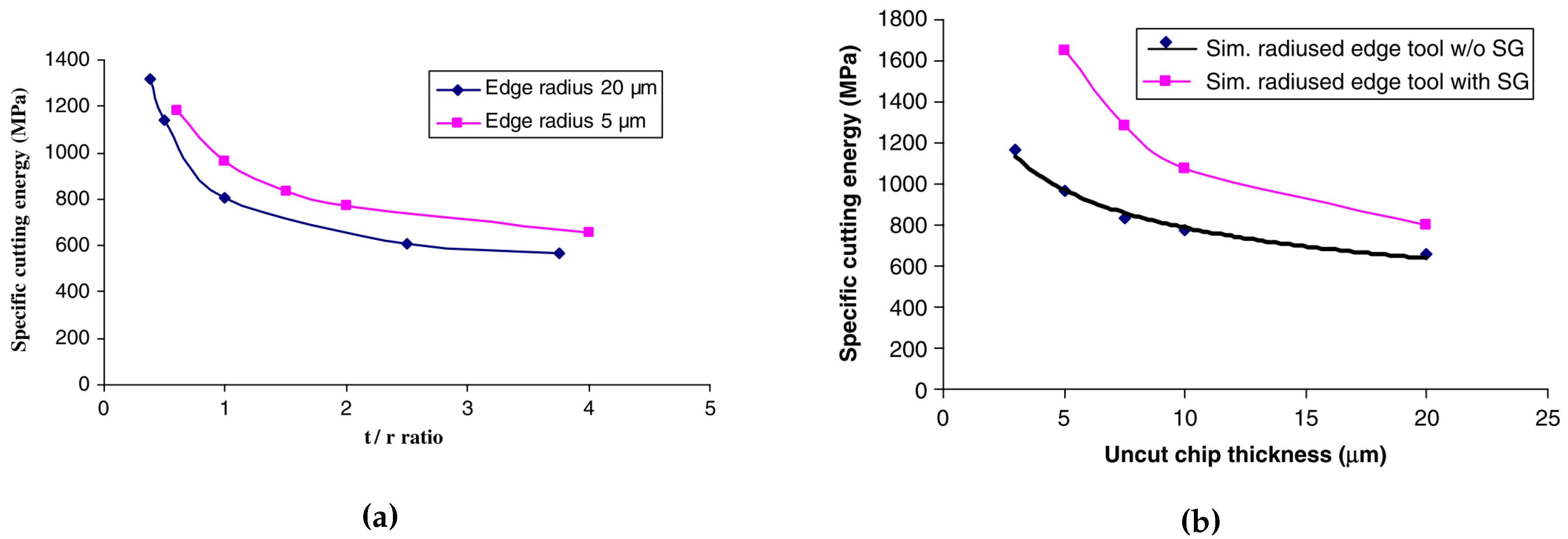
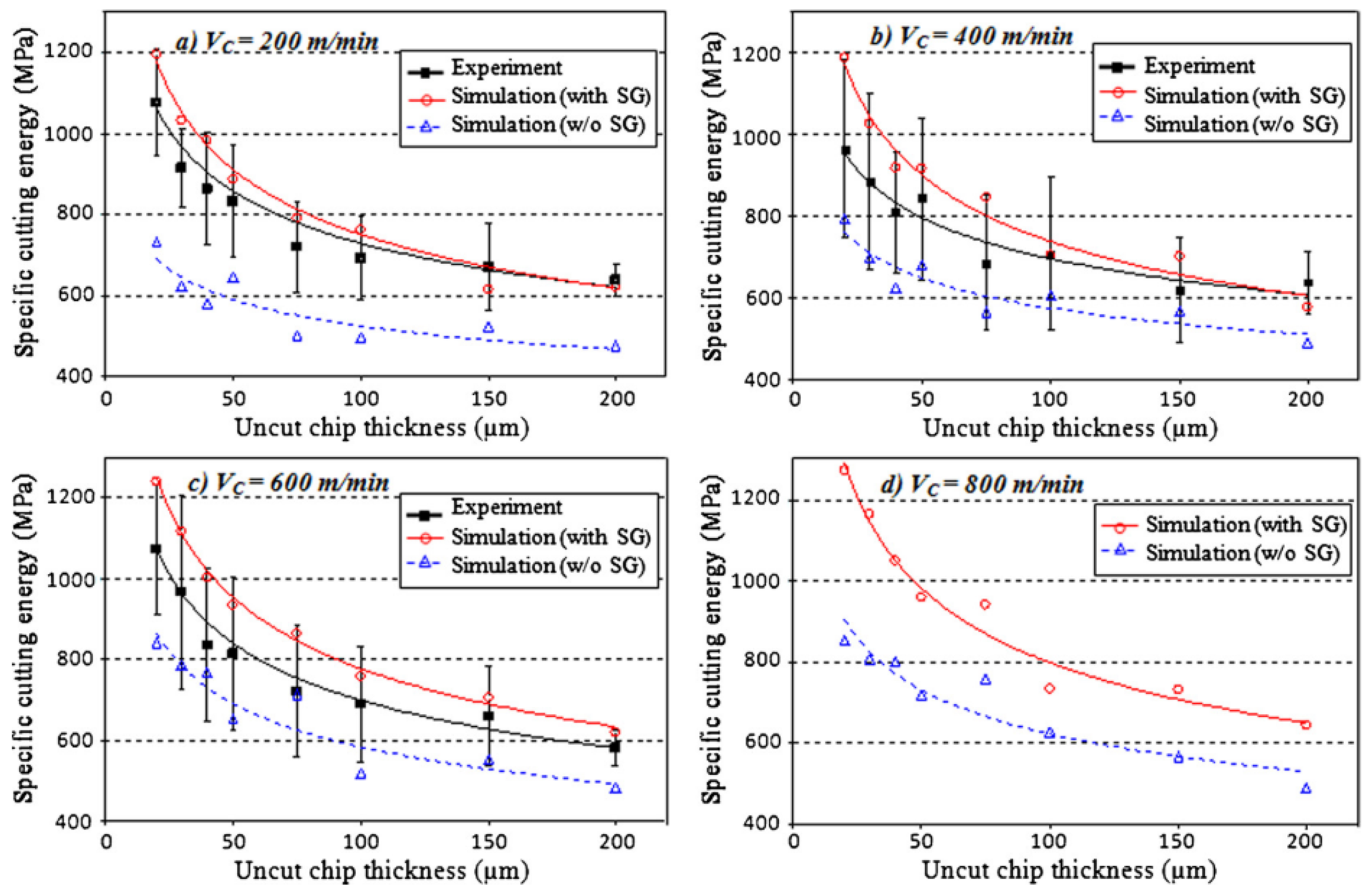
4.3. MSGT Applied to Orthogonal Cutting

The first line of research here reported is the one originated from Liu et al. [8,115,116]. They implemented the Mix-Gao MSGT, thereby adopting a non-local Taylor-derived material hardening description as in Equation (34), where the equivalent measure of the strain gradient was evaluated as in Equation (33), and they used a non-local volume integral to evaluate the strain gradient at every integration point as proposed by Gao and Huang [117]:
η i j k = V ε i k ξ j + ε j k ξ i ε i j ξ k 1 4 δ i k ξ j + δ j k ξ i ε p p d V V ξ m ξ k d V 1 ;
where ξ i is the i-th local coordinate over which integration is performed. In this framework, the classical continuum mechanics description stays the same, and the strain gradient effects only the plastic flow, acting as an additional source of hardening (this is after all the reasoning behind the MSTG). The flow stress they used is the one in Equation (34), and they used the Johnson–Cook evolution of the flow stress to replace f [118]. The characteristic length was identified with:
l = 18 α 2 μ σ Y 2 b ;
They implemented this model in a Finite Element Procedure, using ABAQUS® Implicit through a UMAT FORTRAN subroutine, and they used this model to study the effect of the radius of the cutting tool during orthogonal micro-cutting [8], and to verify the increments in material hardening and cutting energy by using the SGPT [116]. In Figure 10a a comparison is reported from the work of Liu et al. in terms of Specific Cutting energy while using different tool radii. In Figure 10b instead, the effect of using the SGPT is reported again in terms of Specific Cutting Energy. They used a sticking-sliding friction model as the one developed by Zorev [70]. The thermal fields during simulations have been solved through the classical heat equation. Heat was assumed to generate at the tool-workpiece contact location due to friction and at the plastic zones due to plastic work; the Taylor–Quinney constant was set to 0.9 (90% of the plastic work would transform into heat) [119]. An adaptive remeshing algorithm was used to obtain chip separation. The minimum mesh size they used measured 0.06 μ m in the cutting zone, with a chip thickness of 0.5 μ m.
The work of Liu et al. represents a big contribution toward the application of SGPTs for machining simulation, both in terms of progress toward the objective and in terms of proof of the fact that SGPT are necessary to achieve it. However, the disadvantages of using a MSGT are that the system of PDE describing the continuum behavior have not been rigorously derived and thermodynamical consistency of the model has not been proved, therefore, for future development, a more complete and rigorous SGPT would be ideally used, or a thermodynamically-consistent MSGT would have be provided.
Another contribution in simulating machining with SGPTs is the one provided by Asad, Mabrouki et al. [120,121,122]. They also used the MSGT as the one used by Liu et al., but they estimated the equivalent strain gradient measure based on geometrical consideration of the workpiece and the tool used for machining operation [121]. This has large implications on the limited applicability of this theory for a generic simulation. They also quantified the characteristic length as in Equation (56). Besides the evaluation of the strain gradient, they used the same flow stress description as the one used by Liu et al., but the chip formation was induced through a damage-enriched Johnson–Cook behavior law, where damage initiation and propagation were defined based on ductile Johnson–Cook fracture behavior [120]. They also used an ABAQUS® Explicit VUMAT subroutine to implement the model. In Figure 11 the difference between using this variety of MSGT and the classical continuum mechanics description is reported for different cutting speeds.

4.4. Micromorphic Media Applied to Forming

The discussed Micromorphic theory is enhancing the medium by nine additional degrees of freedom, this being an equivalent deformation tensor of the microstructure defined at each point of the continuum. It has also been said that the Micropolar and the Microstrain theories are nothing but a constrained version of the Micromorphic theory. Due to the physics that Eringen described with the Micromorphic theory, this terminology associates to the introduction of additional degrees of freedom in the system that are connected with the microstructure. Through the years, many theories that enhance the continuum with additional degrees of freedom have been semantically linked with the Micromorphic theory, although the physics they described was not related to microstructure. However, in the literature, this became an established nomenclature for continuum mechanics theories enhancing the media with additional degrees of freedom.
The additional degree of freedom can be used for different purposes, it can be used for carrying an equivalent measure of the cumulative plastic strain [62,106,107,108] or for an equivalent damage variable [59,64]. In any case, the equation governing the angular momentum (that for classical continuum mechanics ensures the symmetry of the Cauchy stress tensor) transforms into a balance equation for the additional degrees of freedom and it is referred to as generalized balance equation. In case these additional variables are meant to replace already existing variables, the generalized balance equation transforms into a coupling equation between additional and already existing variables.
In 2017, Diamantopoulou et al. used the Micromorphic theory to enhance the continuum with one scalar additional degree of freedom (meant to represent the damage variable of the medium) and they simulated some metal forming processes with this theory [123]. The enhanced internal power of the continuum reads:
p ( i ) = σ : u ˙ ̲ + Y d ˙ + Z ̲ · ̲ d ˙ ;
where σ is the Cauchy stress tensor, d is the additional Micromorphic damage variable, Y and Z ̲ are higher order stresses associated to the damage variable and its gradient respectively. The description of the theory continues with the considerations related to the thermodynamical admissibility of the theory: the definition of the Helmholtz free energy, the definition of the dissipation potential and the subsequent derivation of the material constitutive behavior and the elastoplastic flow rules from the previously defined potentials. In this medium description, the characteristic length appears in the generalized balance equation coupled with the gradient of the Micromorphic damage variable.
The theory was implemented in ABAQUS® Explicit, through a VUEL subroutine. The introduction of an additional degree of freedom implies a modification of the system of PDEs to be solved, thereby compelling the modification of the Finite Element description rather than an higher-level modification of the material module.
The authors verified the developed formulation through tensile test and bending both performed using the material parameters of the DP1000 steel. The results of their analysis demonstrated an embedded mesh regularization property of the model, that was proven by varying the mesh size, whereas the global force-displacement graphs remained unchanged.

5. Conclusions

By distinguishing between higher order and higher grade formulations, the choice of implementing a continuum mechanics theory belonging to one group or the other depends on the specifications of the process that must be simulated. In general, higher grade theories are more complex to be implemented from a FEM point-of-view, whereas higher order theories are, in most cases, an extension of the classical FEM implementation to an higher number of degrees of freedom, thereby they result more straightforwardly implementable. In Table 1 the main characteristics of the presented SGPTs are reported.
For the simulation of machining operations that involve the development of high temperatures, regardless of the choice between higher order or higher degree, it is require the adoption of a theory incorporating a thermodynamical description that would ensures a proper thermodynamically-consistent description. The suggested approach would be to define the dissipation potential and the Helmholtz free energy from which the constitutive behavior of the medium would directly follow. If higher temperatures are foreseen, the dissipation potential assumes a fundamental role in determining the material response, thereby a proper calibration of the potential at operational conditions is required. If extremely high temperature develops, e.g., through the friction stir welding technique, melting temperature is likely to occur, and the solid description of the medium is not adequate anymore, since the continuum behaves as liquid rather than solid, therefore a mixed Lagrangian-Eulerian formulation is required to performed the simulation. However, the effect of the strain gradient during friction stir welding is not the main character of the whole process, therefore this manufacturing technique is left out of this manuscript.
One of the main drawback of the majority of the higher order theories is that, since the plastic strain is an additional variable of the system, the boundary conditions in terms of plastic strain must be applied at the moving elasto-plastic boundary, so another additional step is required to identify this boundary inside the original domain. Furthermore, if the simulated manufacturing technique involves the development of plastic strain at the domain boundaries, e.g., orthogonal cutting, then the choice related to the type of boundary conditions (in terms of plastic strain) that must be applied at this boundary is very important. If, however, the process that must be simulated does not involve the production of plastic strain at the boundary, then this question does not need to be posed, and the choice of using this type of continuum theory is not unfavorable. Two simulations of orthogonal cutting using SGPTs were reported, and both of them are using MSGT. In light of the previous discussion, the choice of the MSGT is a smart solution, since it has already been mentioned that this type of SGPT does not require the plastic strain field to be solved through PDEs, therefore it is not characterized by this type of problem.
To conclude, the choice of the SGPT to be adopted for simulations of manufacturing operations must be taken while looking at several characteristic of the observed phenomena occurring during the process:
  • The forces/moments used to shear/shape the continuum localize in areas that are comparable to the grain size of the metal; in this case a further hardening due to the dislocations movement must be properly captured by adopting a SGPT;
  • The velocity with which the continuum is deformed might induce material to behave viscously, and this must be covered by a proper design of the material behavior;
  • The temperature developed during the process might be relatively high, and this imposes to considerate the thermal behavior (often adiabatic) that are taken into account by the definition of a thermodynamically-consistent description of the continuum;
  • Implementation-wise if the plastic deformation is expected to occur at the boundaries, a higher degree theory is favorable.

Funding

This project has received funding from the European Union’s Marie Skłodowska-Curie Action (MSCA) Innovative Training Network (ITN) H2020-MSCA-ITN-2017 under the grant agreement n 764979.

Acknowledgments

The first author would like to thank Tim Smithers for the help and guidance provided both during and after the duration of the PhDing course Designing and Building a Critical State of the Art for Research.

Conflicts of Interest

The authors declare that no conflict of interests exists at the time this manuscript has been published. The authors verified that the copyrights covering the material reported in this manuscript from other sources were respected. Furthermore, the authors declare that they reported the results of other researchers with a purely critical attitude, and with no intent of discrediting the researches pursued by colleagues.

Appendix A. Notation

Einstein’s convention is employed in the whole manuscript. Tensors are indicated through compact notation or index notation, regardless of capital or not-capital letters:
a ̲ a i ; a a i j ; a a i j k ; a a i j k l ;
The outer product is indicated with ⊗ and it operates in the following manner:
A B = C A i j B k l = C i j k l ;
Single and double contraction operators are respectively indicated as follows:
A · B = C A i j k B k l m = C i j l m ; A : B = C A i j k B j k l = C i l ;
Divergence and gradient operators are represented as:
A ̲ = B A i j x k = B i j k ; A · ̲ = B ̲ A i j x j = B i ;
where x i is the i-th Cartesian coordinate of an Eulerian space. When handling with skew-symmetric second order tensors, it might be easier to define the first order tensor associated to it as:
A ̲ = 1 2 ϵ : B ;
where ϵ is the Levi-Civita permutation symbol.

Appendix B. Methodology Used to Prepare the Review

Over the course of almost one year, the network of papers grew up from a core of 60 initially-suggested papers from the authors. Further relevant contributions were collected and selected from the references cited in the papers. Almost a dozen of relevant groups of researchers worldwide were identified during this investigation. The main sources of information were the on-line libraries of the Universities involved in the development of this manuscript and web of science, with which the network of publications was built. The scrutinized papers went through a first round of selection in which the relevance of their abstract and conclusion was used as filter. Accepted articles were read and cataloged using the free software MENDELEY©. More than 400 papers were downloaded and scrutinized, and this review paper makes use of almost 26% of them. The papers that were selected but not used were excluded from the research because of the poor relevance with the research questions we were trying to address.

References

  1. Joshi, S.S.; Melkote, S.N. An Explanation for the Size-Effect in Machining Using Strain Gradient Plasticity. J. Manuf. Sci. Eng. 2004, 126, 679. [Google Scholar] [CrossRef]
  2. Royer, R.; Darnis, P.; Laheurte, R.; Gérard, A.; Cahuc, O. Finite strain gradient plasticity theory for high speed machining. Procedia Eng. 2011, 10, 2312–2317. [Google Scholar] [CrossRef] [Green Version]
  3. Voyiadjis, G.Z.; Deliktas, B. Formulation of strain gradient plasticity with interface energy in a consistent thermodynamic framework. Int. J. Plast. 2009, 25, 1997–2024. [Google Scholar] [CrossRef]
  4. Wu, J.; Liu, Z. Modeling of flow stress in orthogonal micro-cutting process based on strain gradient plasticity theory. Int. J. Adv. Manuf. Technol. 2010, 46, 143–149. [Google Scholar] [CrossRef] [Green Version]
  5. Huang, J.; Kalaitzidou, K.; Sutherland, J.W.; Milligan, W.W.; Aifantis, E.C.; Sievert, R.; Forest, S. Gradient Plasticity: Implications to Chip Formation in Machining. In Proceedings of the 4th International ESAFORM Conference on Material Forming, Liege, Belgium, 23–25 April 2001; pp. 527–530. [Google Scholar]
  6. Laheurte, R.; Cahuc, O.; Darnis, P.; Gerard, A. Behaviour law for cutting process. Int. J. Adv. Manuf. Technol. 2006, 29, 17–23. [Google Scholar] [CrossRef]
  7. Cahuc, O.; Darnis, P.; Laheurte, R. Mechanical and Thermal Experiments in Cutting Process for New Behaviour Law. Int. J. Form. Process. 2007, 10, 235–269. [Google Scholar] [CrossRef]
  8. Liu, K.; Melkote, S.N. Finite element analysis of the influence of tool edge radius on size effect in orthogonal micro-cutting process. Int. J. Mech. Sci. 2007, 49, 650–660. [Google Scholar] [CrossRef]
  9. Wang, X.B. Adiabatic Shear Localization for Steels Based on Johnson–Cook Model and Second- and Fourth-Order Gradient Plasticity Models. J. Iron Steel Res. Int. 2007, 14, 56–61. [Google Scholar] [CrossRef]
  10. Demir, E. A Taylor-based plasticity model for orthogonal machining of single-crystal FCC materials including frictional effects. Int. J. Adv. Manuf. Technol. 2009, 40, 847–856. [Google Scholar] [CrossRef] [Green Version]
  11. Jing, X.B.; Lin, B.; Zhang, D.W. Modeling and analysis of factors of size effect in micro-cutting: The tool geometry and the depth of cutting. In Proceedings of the 2013 International Conference on Manipulation, Manufacturing and Measurement on the Nanoscale (3M-NANO 2013), Suzhou, China, 26–30 August 2013; pp. 314–318. [Google Scholar] [CrossRef]
  12. Molinari, A.; Musquar, C.; Sutter, G. Adiabatic shear banding in high speed machining of Ti-6Al-4V: Experiments and modeling. Int. J. Plast. 2002, 18, 443–459. [Google Scholar] [CrossRef]
  13. Ye, G.G.; Chen, Y.; Xue, S.F.; Dai, L.H. Critical cutting speed for onset of serrated chip flow in high speed machining. Int. J. Mach. Tools Manuf. 2014, 86, 18–33. [Google Scholar] [CrossRef]
  14. Dixit, U.S.; Joshi, S.N.; Davim, J.P. Incorporation of material behavior in modeling of metal forming and machining processes: A review. Mater. Des. 2011, 32, 3655–3670. [Google Scholar] [CrossRef]
  15. Tang, B.; Xiang, L.; Cheng, L.; Liu, D.; Kou, H.; Li, J. The formation and evolution of shear bands in plane strain compressed nickel-base superalloy. Metals 2018, 8, 141. [Google Scholar] [CrossRef] [Green Version]
  16. Calamaz, M.; Coupard, D.; Girot, F. A new material model for 2D numerical simulation of serrated chip formation when machining titanium alloy Ti-6Al-4V. Int. J. Mach. Tools Manuf. 2008, 48, 275–288. [Google Scholar] [CrossRef] [Green Version]
  17. List, G.; Sutter, G.; Bi, X.F.; Molinari, A.; Bouthiche, A. Strain, strain rate and velocity fields determination at very high cutting speed. J. Mater. Process. Technol. 2013, 213, 693–699. [Google Scholar] [CrossRef]
  18. Lee, S.; Hwang, J.; Ravi Shankar, M.; Chandrasekar, S.; Compton, W.D. Large strain deformation field in machining. Metall. Mater. Trans. A: Phys. Metall. Mater. Sci. 2006, 37, 1633–1643. [Google Scholar] [CrossRef]
  19. Chinesta, F.; Ladeveze, P.; Cueto, E. A Short Review on Model Order Reduction Based on Proper Generalized Decomposition. Arch. Comput. Methods Eng. 2011, 18, 395–404. [Google Scholar] [CrossRef] [Green Version]
  20. Fleck, N.A.; Hutchinson, J.W. Strain Gradient Plasticity. Adv. Appl. Mech. 1997, 33, 295–361. [Google Scholar] [CrossRef]
  21. Stölken, J.S.; Evans, A.G. A microbend test method for measuring the plasticity length scale. Acta Mater. 1998, 46, 5109–5115. [Google Scholar] [CrossRef]
  22. Begley, M.R.; Hutchinson, J.W. The mechanics of size-dependent indentation. J. Mech. Phys. Solids 1998, 46, 2049–2068. [Google Scholar] [CrossRef]
  23. Poole, W.; Ashby, M.; Fleck, N. Micro-hardness of annealed and work-hardened copper polycrystals. Scr. Mater. 1996, 34, 559–564. [Google Scholar] [CrossRef]
  24. Nix, W.D.; Gao, H. Indentation size effects in crystalline materials: A law for strain gradient plasticity. J. Mech. Phys. Solids 1998, 46, 411–425. [Google Scholar] [CrossRef]
  25. Ma, Q.; Clarke, D.R. Size dependent hardness of silver single crystals. J. Mater. Res. 1995, 10, 853–863. [Google Scholar] [CrossRef]
  26. González, D.; Alkorta, J.; Martínez-Esnaola, J.M.; Gil Sevillano, J. Numerical analysis of the indentation size effect using a strain gradient crystal plasticity model. Comput. Mater. Sci. 2014, 82, 314–319. [Google Scholar] [CrossRef]
  27. Stelmashenko, N.A.; Walls, M.G.; Brown, L.M.; Milman, Y.V. Microindentations on W and Mo oriented single crystals: An STM study. Acta Metall. Mater. 1993, 41, 2855–2865. [Google Scholar] [CrossRef]
  28. Panteghini, A.; Bardella, L. On the Finite Element implementation of higher-order gradient plasticity, with focus on theories based on plastic distortion incompatibility. Comput. Methods Appl. Mech. Eng. 2016, 310, 840–865. [Google Scholar] [CrossRef]
  29. Han, C.S.; Ma, A.; Roters, F.; Raabe, D. A Finite Element approach with patch projection for strain gradient plasticity formulations. Int. J. Plast. 2007, 23, 690–710. [Google Scholar] [CrossRef]
  30. Dahlberg, C.F.; Faleskog, J. An improved strain gradient plasticity formulation with energetic interfaces: Theory and a fully implicit finite element formulation. Comput. Mech. 2013, 51, 641–659. [Google Scholar] [CrossRef]
  31. Askes, H.; Aifantis, E.C. Gradient elasticity in statics and dynamics: An overview of formulations, length scale identification procedures, finite element implementations and new results. Int. J. Solids Struct. 2011, 48, 1962–1990. [Google Scholar] [CrossRef]
  32. Gurtin, M.E.; Anand, L. A theory of strain-gradient plasticity for isotropic, plastically irrotational materials. Part II: Finite deformations. Int. J. Plast. 2005, 21, 2297–2318. [Google Scholar] [CrossRef]
  33. Liu, D.; Dunstan, D.J. Material length scale of strain gradient plasticity: A physical interpretation. Int. J. Plast. 2017, 98, 156–174. [Google Scholar] [CrossRef]
  34. Al-Rub, R.K.A.; Voyiadjis, G.Z. Determination of the Material Intrinsic Length Scale of Gradient Plasticity Theory. Int. J. Multiscale Comput. Eng. 2005, 2, 377–400. [Google Scholar] [CrossRef]
  35. Duan, D.M.; Wu, N.Q.; Slaughter, W.S.; Mao, S.X. Length scale effect on mechanical behavior due to strain gradient plasticity. Mater. Sci. Eng. A 2001, 303, 241–249. [Google Scholar] [CrossRef]
  36. Aifantis, E.C. Strain gradient interpretation of size effects. Int. J. Fract. 1999, 95, 299–314. [Google Scholar] [CrossRef]
  37. Liu, D.; He, Y.; Dunstan, D.J.; Zhang, B.; Gan, Z.; Hu, P.; Ding, H. Toward a further understanding of size effects in the torsion of thin metal wires: An experimental and theoretical assessment. Int. J. Plast. 2013, 41, 30–52. [Google Scholar] [CrossRef]
  38. Liu, D.; He, Y.; Dunstan, D.J.; Zhang, B.; Gan, Z.; Hu, P.; Ding, H. Anomalous plasticity in the cyclic torsion of micron scale metallic wires. Phys. Rev. Lett. 2013, 110, 1–5. [Google Scholar] [CrossRef] [Green Version]
  39. Ehrler, B.; Hou, X.D.; Zhu, T.T.; P’Ng, K.M.; Walker, C.J.; Bushby, A.J.; Dunstan, D.J. Grain size and sample size interact to determine strength in a soft metal. Philos. Mag. 2008, 88, 3043–3050. [Google Scholar] [CrossRef] [Green Version]
  40. Dunstan, D.J.; Ehrler, B.; Bossis, R.; Joly, S.; P’Ng, K.M.; Bushby, A.J. Elastic Limit and Strain Hardening of Thin Wires in Torsion. Phys. Rev. Lett. 2009, 103, 1–4. [Google Scholar] [CrossRef] [Green Version]
  41. Fleck, N.A.; Muller, G.M.; Ashby, M.F.; Hutchinson, J.W. Strain gradient plasticity: Theory and experiment. Acta Metall. Mater. 1994, 42, 475–487. [Google Scholar] [CrossRef]
  42. Fleck, N.A.; Hutchinson, J.W. A reformulation of strain gradient plasticity. J. Mech. Phys. Solids 2001, 49, 2245–2271. [Google Scholar] [CrossRef] [Green Version]
  43. Dahlberg, C.F.; Boåsen, M. Evolution of the length scale in strain gradient plasticity. Int. J. Plast. 2019, 112, 220–241. [Google Scholar] [CrossRef]
  44. Zhang, X.; Aifantis, K. Interpreting the internal length scale in strain gradient plasticity. Rev. Adv. Mater. Sci. 2015, 41, 72–83. [Google Scholar]
  45. Yuan, H.; Chen, J. Identification of the intrinsic material length in gradient plasticity theory from micro-indentation tests. Int. J. Solids Struct. 2001, 38, 8171–8187. [Google Scholar] [CrossRef]
  46. Abu Al-Rub, R.K.; Voyiadjis, G.Z. Analytical and experimental determination of the material intrinsic length scale of strain gradient plasticity theory from micro- and nano-indentation experiments. Int. J. Plast. 2004, 20, 1139–1182. [Google Scholar] [CrossRef]
  47. De Borst, R.; Mühlhaus, H.B. Gradient-dependent plasticity: Formulation and algorithmic aspects. Int. J. Numer. Methods Eng. 1992, 35, 521–539. [Google Scholar] [CrossRef] [Green Version]
  48. Benallal, A.; Berstad, T.; Børvik, T.; Hopperstad, O.S. Uniqueness, loss of ellipticity and localization for the time-discretized, rate-dependent boundary value problem with softening. Int. J. Numer. Methods Eng. 2010, 84, 864–882. [Google Scholar] [CrossRef]
  49. Wcisło, B.; Pamin, J.; Kowalczyk-Gajewska, K.; Menzel, A. Numerical analysis of ellipticity condition for large strain plasticity. AIP Conf. Proc. 2018, 1922. [Google Scholar] [CrossRef]
  50. Jirásek, M.; Rolshoven, S. Localization properties of strain-softening gradient plasticity models. Part I: Strain-gradient theories. Int. J. Solids Struct. 2009, 46, 2225–2238. [Google Scholar] [CrossRef] [Green Version]
  51. Toupin, R.A. Elastic materials with couple-stresses. Arch. Ration. Mech. Anal. 1962, 11, 385–414. [Google Scholar] [CrossRef] [Green Version]
  52. Mindlin, R.D. Micro-structure in linear elasticity. Arch. Ration. Mech. Anal. 1964, 16, 51–78. [Google Scholar] [CrossRef]
  53. Chambon, R.; Caillerie, D.; El Hassan, N. One-dimensional localisation studied with a second grade model. Eur. J. Mech. A/Solids 1998, 17, 637–656. [Google Scholar] [CrossRef]
  54. Qiu, X.; Huang, Y.; Wei, Y.; Gao, H.; Hwang, K.C. The flow theory of mechanism-based strain gradient plasticity. Mech. Mater. 2003, 35, 245–258. [Google Scholar] [CrossRef] [Green Version]
  55. Nguyen, G.D.; Korsunsky, A.M.; Belnoue, J.P. A nonlocal coupled damage-plasticity model for the analysis of ductile failure. Int. J. Plast. 2015, 64, 56–75. [Google Scholar] [CrossRef]
  56. Lele, S.P.; Anand, L. A large-deformation strain-gradient theory for isotropic viscoplastic materials. Int. J. Plast. 2009, 25, 420–453. [Google Scholar] [CrossRef]
  57. Mediavilla, J.; Peerlings, R.H.; Geers, M.G. An integrated continuous-discontinuous approach towards damage engineering in sheet metal forming processes. Eng. Fract. Mech. 2006, 73, 895–916. [Google Scholar] [CrossRef]
  58. Brepols, T.; Wulfinghoff, S.; Reese, S. Gradient-extended two-surface damage-plasticity: Micromorphic formulation and numerical aspects. Int. J. Plast. 2017, 97, 64–106. [Google Scholar] [CrossRef]
  59. Saanouni, K.; Hamed, M. Micromorphic approach for finite gradient-elastoplasticity fully coupled with ductile damage: Formulation and computational aspects. Int. J. Solids Struct. 2013, 50, 2289–2309. [Google Scholar] [CrossRef] [Green Version]
  60. Peerlings, R.H.J.; De Borst, R.; Brekelmans, W.A.M.; De Vree, J.H.P. Gradient Enhanced Damage for Quasi-brittle Materials. Int. J. Numer. Methods Eng. 1996, 39, 3391–3403. [Google Scholar] [CrossRef]
  61. Sabet, S.A.; de Borst, R. Structural softening, mesh dependence, and regularisation in non-associated plastic flow. Int. J. Numer. Anal. Methods Geomech. 2019, 43, 2170–2183. [Google Scholar] [CrossRef]
  62. Mazière, M.; Forest, S. Strain gradient plasticity modeling and finite element simulation of Lüders band formation and propagation. Contin. Mech. Thermodyn. 2013, 27, 83–104. [Google Scholar] [CrossRef]
  63. Ling, C.; Forest, S.; Besson, J.; Tanguy, B.; Latourte, F. A reduced micromorphic single crystal plasticity model at finite deformations. Application to strain localization and void growth in ductile metals. Int. J. Solids Struct. 2018, 134, 43–69. [Google Scholar] [CrossRef]
  64. Forest, S. Micromorphic Approach for Gradient Elasticity, Viscoplasticity, and Damage. J. Eng. Mech. 2009, 135, 117–131. [Google Scholar] [CrossRef]
  65. Peirs, J.; Verleysen, P.; Degrieck, J.; Coghe, F. The use of hat-shaped specimens to study the high strain rate shear behaviour of Ti-6Al-4V. Int. J. Impact Eng. 2010, 37, 703–714. [Google Scholar] [CrossRef] [Green Version]
  66. Marchand, A.; Duffy, J. An experimental study of the formation process of adiabatic shear bands in a structural steel. J. Mech. Phys. Solids 1988, 36, 251–283. [Google Scholar] [CrossRef]
  67. Rahmaan, T.; Zhou, P.; Butcher, C.; Worswick, M.J. Strain rate and thermal softening effects in shear testing of AA7075-T6 sheet. EPJ Web Conf. 2018, 183, 02037. [Google Scholar] [CrossRef]
  68. Chen, G.; Ren, C.; Yang, X.; Jin, X.; Guo, T. Finite element simulation of high-speed machining of titanium alloy (Ti-6Al-4V) based on ductile failure model. Int. J. Adv. Manuf. Technol. 2011, 56, 1027–1038. [Google Scholar] [CrossRef]
  69. Astakov, V. (Ed.) Tribology and Interface Engineering Series. In Tribology of Metal Cutting, 1st ed.; Elsevier B.V.: Amsterdam, The Netherlands, 2006; Chapter 3; pp. 124–219. [Google Scholar] [CrossRef]
  70. Zorev, N. Inter-relationship between shear processes occurring along tool face and shear plane in metal cutting. Int. Res. Prod. Eng. 1963, 49, 143–152. [Google Scholar]
  71. Shirakashi, T.; Usui, E. Friction Characteristics on Tool Face in Metal Machining. J. Jpn. Soc. Precis. Eng. 1973, 39, 966–972. [Google Scholar] [CrossRef]
  72. Childs, T.H. Friction modelling in metal cutting. Wear 2006, 260, 310–318. [Google Scholar] [CrossRef]
  73. Bahi, S.; Nouari, M.; Moufki, A.; Mansori, M.E.; Molinari, A. Hybrid modelling of sliding-sticking zones at the tool-chip interface under dry machining and tool wear analysis. Wear 2012, 286–287, 45–54. [Google Scholar] [CrossRef]
  74. Bahi, S.; Nouari, M.; Moufki, A.; El Mansori, M.; Molinari, A. A new friction law for sticking and sliding contacts in machining. Tribol. Int. 2011, 44, 764–771. [Google Scholar] [CrossRef]
  75. Ackroyd, B.; Chandrasekar, S.; Compton, W.D. A Model for the Contact Conditions at the Chip-Tool Interface in Machining. J. Tribol. 2003, 125, 649. [Google Scholar] [CrossRef]
  76. Eringen, A.C. Nonlinear Theory of Continuous Media; McGraw-Hill: New York, NY, USA, 1962. [Google Scholar]
  77. Gurtin, M.E. An Introduction to Continuum Mechanics; Academic Press: Cambridge, MA, USA, 1981; p. 265. [Google Scholar]
  78. Forest, S.; Sievert, R. Nonlinear microstrain theories. Int. J. Solids Struct. 2006, 43, 7224–7245. [Google Scholar] [CrossRef]
  79. Aifantis, E.C. On the Microstructural Origin of Certain Inelastic Models. J. Eng. Mater. Technol. 1984, 106, 326. [Google Scholar] [CrossRef]
  80. Aifantis, E.C. The physics of plastic deformation. Int. J. Plast. 1987, 3, 211–247. [Google Scholar] [CrossRef]
  81. Gudmundson, P. A unified treatment of strain gradient plasticity. J. Mech. Phys. Solids 2004, 52, 1379–1406. [Google Scholar] [CrossRef]
  82. Steinmann, P. Views on multiplicative elastoplasticity and the continuum theory of dislocations. Int. J. Eng. Sci. 1996, 34, 1717–1735. [Google Scholar] [CrossRef]
  83. Gurtin, M.E.; Anand, L. Thermodynamics applied to gradient theories involving the accumulated plastic strain: The theories of Aifantis and Fleck and Hutchinson and their generalization. J. Mech. Phys. Solids 2009, 57, 405–421. [Google Scholar] [CrossRef]
  84. Toupin, R.A. Theories of elasticity with couple-stress. Arch. Ration. Mech. Anal. 1964, 17, 85–112. [Google Scholar] [CrossRef]
  85. Fleck, N.; Hutchinson, J. A phenomenological theory for strain gradient effects in plasticity. J. Mech. Phys. Solids 1993, 41, 1825–1857. [Google Scholar] [CrossRef]
  86. Smyshlyaev, V.; Fleck, N. The role of strain gradients in the grain size effect for polycrystals. J. Mech. Phys. Solids 1996, 44, 465–495. [Google Scholar] [CrossRef]
  87. Fleck, N.; Willis, J. A mathematical basis for strain-gradient plasticity theory—Part I: Scalar plastic multiplier. J. Mech. Phys. Solids 2009, 57, 161–177. [Google Scholar] [CrossRef]
  88. Hutchinson, J.W. Generalizing J2 flow theory: Fundamental issues in strain gradient plasticity. Acta Mech. Sin. Xuebao 2012, 28, 1078–1086. [Google Scholar] [CrossRef] [Green Version]
  89. Gurtin, M.E.; Anand, L. A theory of strain-gradient plasticity for isotropic, plastically irrotational materials. Part I: Small deformations. J. Mech. Phys. Solids 2005, 53, 1624–1649. [Google Scholar] [CrossRef]
  90. Gao, H.; Huang, Y.; Nix, W.; Hutchinson, J. Mechanism-based strain gradient plasticity—I. Theory. J. Mech. Phys. Solids 1999, 47, 1239–1263. [Google Scholar] [CrossRef]
  91. Huang, Y.; Gao, H.; Nix, W.D.; Hutchinson, J.W. Mechanism-based strain gradient plasticity—II. Analysis. J. Mech. Phys. Solids 2000, 48, 99–128. [Google Scholar] [CrossRef]
  92. Taylor, G.I. Plastic Strain in Metals. J. Inst. Met. 1938, 62, 307–325. [Google Scholar]
  93. Nye, J.F. Some geometrical relations in dislocated crystals. Acta Metall. 1953, 1, 153–162. [Google Scholar] [CrossRef]
  94. Ashby, M.F. The deformation of plastically non-homogeneous materials. Philos. Mag. 1970, 21, 399–424. [Google Scholar] [CrossRef]
  95. Niordson, C.F.; Hutchinson, J.W. On lower order strain gradient plasticity theories. Eur. J. Mech. A/Solids 2003, 22, 771–778. [Google Scholar] [CrossRef]
  96. Menzel, A.; Steinmann, P. On the continuum formulation of higher gradient plasticity for single and polycrystals. J. Mech. Phys. Solids 2000, 48, 1777–1796. [Google Scholar] [CrossRef]
  97. Wulfinghoff, S.; Böhlke, T. Equivalent plastic strain gradient enhancement of single crystal plasticity: Theory and numerics. Proc. R. Soc. Math. Phys. Eng. Sci. 2012, 468, 2682–2703. [Google Scholar] [CrossRef] [Green Version]
  98. Wulfinghoff, S.; Bayerschen, E.; Böhlke, T. A gradient plasticity grain boundary yield theory. Int. J. Plast. 2013, 51, 33–46. [Google Scholar] [CrossRef]
  99. Cosserat, E.; Cosserat, F. Theorie des Corps Deformables. Nature 1909, 81, 67. [Google Scholar] [CrossRef]
  100. Koiter, W.T. Couple Stresses in the Theory of Elasticity, I & II. Philos. Trans. R. Soc. Lond. 1964, 67, 17–44. [Google Scholar]
  101. Khoei, A.R.; Yadegari, S.; Biabanaki, S.O. 3D finite element modeling of shear band localization via the micro-polar Cosserat continuum theory. Comput. Mater. Sci. 2010, 49, 720–733. [Google Scholar] [CrossRef]
  102. De Borst, R. Simulation of strain localization: A reappraisal of the cosserat continuum. Eng. Comput. 1991, 8, 317–332. [Google Scholar] [CrossRef]
  103. Eringen, A.C.; Suhubi, E.S. Nonlinear theory of simple micro-elastic solids-I. Int. J. Eng. Sci. 1964, 2, 189–203. [Google Scholar] [CrossRef]
  104. Eringen, A.C. Microcontinuum Field Theories: I. Foundations and Solids, 1st ed.; Springer: New York, NY, USA, 1999. [Google Scholar]
  105. Dillard, T.; Forest, S.; Ienny, P. Micromorphic continuum modelling of the deformation and fracture behaviour of nickel foams. Eur. J. Mech. A/Solids 2006, 25, 526–549. [Google Scholar] [CrossRef] [Green Version]
  106. Anand, L.; Aslan, O.; Chester, S.A. A large-deformation gradient theory for elastic-plastic materials: Strain softening and regularization of shear bands. Int. J. Plast. 2012, 30–31, 116–143. [Google Scholar] [CrossRef]
  107. Poh, L.H.; Peerlings, R.H.J.; Geers, M.G.D.; Swaddiwudhipong, S. An implicit tensorial gradient plasticity model - Formulation and comparison with a scalar gradient model. Int. J. Solids Struct. 2011, 48, 2595–2604. [Google Scholar] [CrossRef] [Green Version]
  108. Peerlings, R.H.J. On the role of moving elastic-plastic boundaries in strain gradient plasticity. Model. Simul. Mater. Sci. Eng. 2007, 15. [Google Scholar] [CrossRef] [Green Version]
  109. Acharya, A.; Bassani, J.L. On Non-Local Flow Theories that Preserve the Classical Structure of Incremental Boundary Value Problems. In IUTAM Symposium on Micromechanics of Plasticity and Damage of Multiphase Materials. Solid Mechanics and its Applications; Springer: Dordrecht, The Netherlands, 1996. [Google Scholar] [CrossRef]
  110. Bassani, J.L. Incompatibility and a simple gradient theory of plasticity. J. Mech. Phys. Solids 2001, 49, 1983–1996. [Google Scholar] [CrossRef]
  111. Guha, S.; Sangal, S.; Basu, S. Numerical investigations of flat punch molding using a higher order strain gradient plasticity theory. Int. J. Mater. Form. 2014, 7, 459–467. [Google Scholar] [CrossRef]
  112. Shu, J.Y.; Fleck, N.A. The prediction of a size effect in micro-indentation. Int. J. Solids Struct. 1998, 35, 1363–1383. [Google Scholar] [CrossRef]
  113. Nielsen, K.L.; Niordson, C.F.; Hutchinson, J.W. Rolling at small scales. J. Manuf. Sci. Eng. Trans. ASME 2016, 138, 1–10. [Google Scholar] [CrossRef] [Green Version]
  114. Fleck, N.A.; Willis, J.R. A mathematical basis for strain-gradient plasticity theory. Part II: Tensorial plastic multiplier. J. Mech. Phys. Solids 2009, 57, 1045–1057. [Google Scholar] [CrossRef]
  115. Liu, K. Process Modeling of Micro-Cutting Including Strain Gradient Effects. Ph.D. Thesis, Georgia Institute of Technology, Atlanta, GA, USA, December 2005. [Google Scholar]
  116. Liu, K.; Melkote, S.N. Material strengthening mechanisms and their contribution to size effect in micro-cutting. J. Manuf. Sci. Eng. Trans. ASME 2006, 128, 730–738. [Google Scholar] [CrossRef]
  117. Gao, H.; Huang, Y. Taylor-based nonlocal theory of plasticity. Int. J. Solids Struct. 2001, 38, 2615–2637. [Google Scholar] [CrossRef]
  118. Johnson, G.R.; Cook, W.H. A constitutive model and data from metals subjected to large strains, high strain rates and high temperatures. In Proceedings of the 7th International Symposium on Ballistics, The Hague, The Netherlands, 19–21 April 1983; pp. 541–547. [Google Scholar]
  119. Taylor, G.I.; Quinney, H. The latent energy remaining in a metal after cold working. Proc. R. Soc. A Math. Eng. Sci. 1934, 143, 307–326. [Google Scholar] [CrossRef]
  120. Asad, M.; Mabrouki, T.; Rigal, J.F. Finite-element-based hybrid dynamic cutting model for aluminium alloy milling. Proc. Inst. Mech. Eng. Part B: J. Eng. Manuf. 2010, 224, 1–13. [Google Scholar] [CrossRef]
  121. Asad, M. Elaboration of Concepts and Methodologies to Study Peripheral Down-Cut Milling Process from Macro-To-Micro Scales. Ph.D. Thesis, Institute National des Sciences AppliquéEs de Lyon, Villeurbanne, France, September 2010. [Google Scholar]
  122. Mabrouki, T.; Courbon, C.; Zhang, Y.; Rech, J.; Nélias, D.; Asad, M.; Hamdi, H.; Belhadi, S.; Salvatore, F. Some insights on the modelling of chip formation and its morphology during metal cutting operations. Comptes Rendus—Mec. 2016, 344, 335–354. [Google Scholar] [CrossRef]
  123. Diamantopoulou, E.; Liu, W.; Labergere, C.; Badreddine, H.; Saanouni, K.; Hu, P. Micromorphic constitutive equations with damage applied to metal forming. Int. J. Damage Mech. 2017, 26, 314–339. [Google Scholar] [CrossRef]
Figure 1. Adiabatic Shear Band formation during orthogonal cutting Titanium alloy [12].
Jmmp 04 00087 g001
Figure 2. Shear bands produced during FSW of the Aluminum alloy AA2050 with an advancing side on the left.
Jmmp 04 00087 g002
Figure 3. Variation of Torsional stiffness during torsion test on a copper wire (a) and variation of Hardness during microindentation test on tungsten single crystal (b) [20].
Jmmp 04 00087 g003
Figure 4. Variation of the normalized bending moment on thin Nickle foils during micro-bending test [21].
Jmmp 04 00087 g004
Figure 5. Mesh hypersensitivity demonstrated through compression simulation on a Hat-Specimen [65]. Distribution of equivalent plastic strain obtained for different mesh sizes using the Classical CM (a). Distribution of equivalent plastic strain in case a Generalized CM (Cosserat Medium) is used (b). Boundary conditions and geometry of the axial-symmetric cross section of the Hat-Specimen used for simulation (c). The red line in (c) indicates the location where the equivalent plastic strain was sampled.
Jmmp 04 00087 g005
Figure 6. Measured Temperature field in a torsional Kolsky test at a strain rate of 1600 s 1 [66].
Jmmp 04 00087 g006
Figure 7. (a) Correlation between the measured temperature field and the stress-strain curve in a shear test performed at a strain rate of 500 s−1. (b) Difference between the temperature fields measured during two shear tests at different strain rates [67].
Jmmp 04 00087 g007
Figure 8. Temperature distribution in the chip during orthogonal cutting on AISI 1045 steel obtained with a camera in circumferential (a) and axial (b) directions [69].
Jmmp 04 00087 g008
Figure 9. Predicted characteristic hardness against the characteristic length using the viscoplastic model of Fleck2001 SGT [111]. w is half the punch width, H is the hardness, σ 0 is the initial material yield stress and l * is the characteristic length as in Equation (20).
Jmmp 04 00087 g009
Figure 10. Predicted effect of the tool radius on the Specific Cutting Energy Variation during orthogonal cutting test (a), and effect of the adoption of a SGT on the predicted Specific Cutting Energy (b) [8].
Jmmp 04 00087 g010
Figure 11. Predicted Specific Cutting Energy Variation during orthogonal cutting test for different cutting speed with and without SGT [122].
Jmmp 04 00087 g011
Table 1. Summary of the presented SGPTs.
Name# d.o.f.# Charact. LengthsAdditional FeatureHigher Order/Higher Grade
Aifantis [36,79,80]31/2 σ Y 2 ε e q p Higher Grade
Fleck1993 [85]32 p ( i ) skew u ̲ ˙ ̲ Higher Grade
Fleck1997 [20]36 p ( i ) u ̲ ̲ ̲ Higher Grade
Fleck2001 [42]31 p ( i ) ε p ̲ Higher Grade
Gurtin [89]32 p ( i ) ( ε p ̲ , θ ) Higher Grade
Gudmundson [81]36 p ( i ) ε p ̲ Higher Grade
Gao [90,91]31 σ Y u ̲ ̲ ̲ Higher Grade
Cosserat [99]63 p ( i ) ( θ , Γ ) Higher Order
Micromorphic [103]122 p ( i ) ( ϕ , ϕ ̲ ) Higher Order

