Article

Green Ceramic Machining: Influence of the Cutting Speed and the Binder Percentage on the Y-TZP Behavior

by
Anthonin Demarbaix
1,*,
François Ducobu
1,
Nicolas Preux
2,
Fabrice Petit
2 and
Edouard Rivière-Lorphèvre
1
1
Machine Design and Production Engineering Unit, Faculty of Engineering, University of Mons, Place du parc 20, 7000 Mons, Belgium
2
Research and Technological Support Department, Environmental Materials Research Association, Belgian Ceramic Research Centre), Avenue Gouverneur Cornez 4, 7000 Mons, Belgium
*
Author to whom correspondence should be addressed.
J. Manuf. Mater. Process. 2020, 4(2), 50; https://doi.org/10.3390/jmmp4020050
Submission received: 27 March 2020 / Revised: 13 May 2020 / Accepted: 19 May 2020 / Published: 21 May 2020
(This article belongs to the Special Issue Advanced Manufacturing and Machining Processes)

Abstract

:
The demand for inert bioceramics is always increasing in the dental field. Yttrium oxide tetragonal zirconia polycrystals (Y-TZP) are oxide ceramics which are currently used because of their interesting mechanical properties due to a toughening transformation. Industrially speaking, machining of the ceramic before sintering (green body) is very common because it allows a better productivity and it reduces crack probability during the sintering process. The goal of this paper is to determine the behavior of green ceramic during the machining operation. This study is carried out on several blanks with different binder percentages. The specific cutting energy (SCE) and the surface quality (Ra and Rz) are determined for several cutting speeds. The SCE follows a logarithmic evolution when the cutting speed increases. Despite this increase, the Ra are relatively stable whatever the cutting speed and the binder percentage. At a low cutting speed, a higher Rz value is observed caused by pullout of material. The increase of cutting speed allows to stabilize the Rz value whatever the binder percentage. This study shows that the green ceramic has a pseudo-plastic behavior whose machinability depends mainly on the interaction between the material and the cutting edge of the tool, so unlike pre-sintered ceramic or metallic part cutting speed has a low influence on the quality of the machined part.

1. Introduction

Nowadays, the demand for miniaturization on the market is continually increasing, including in difficult to machine materials. Micro-manufacturing is mainly used to produce micro-electro-mechanical systems (MEMS), which is a booming field. MEMS are composed of mechanical parts that are controlled by embedded electronics or electrical parts [1]. Nowadays this technology is more and more used in the medical field and is also called “BioMEMS”. BioMEMS can analyze biochemical liquid samples. It is a promising technology for the developments of novel drug delivery systems [1,2]. Bioceramics answer these specific conditions and have other advantages such as chemical inertia and resistance to thermal shocks. In fact, inert bioceramics are ceramics which have a high chemical stability in vivo and a high mechanical strength [3,4]. Yttrium oxide tetragonal zirconia polycrystals (Y-TZP) are one of the most inert bioceramics used in the dental field due to their mechanical properties. Y-TZP has a flexural strength of about 1200 MPa with a fracture toughness of 6–9 MPa.m1/2. Alumina, which is the other popular engineering ceramic, has a flexural strength of 547 MPa with a fracture toughness of about 4 MPa.m1/2 [5]. These properties are caused by the transformation toughening mechanism for Y-TZP. It is the tetragonal-monoclinic transformation which is a martensitic one. It is athermal and it is characterized by a very limited movement of the atoms on distances shorter than an atomic equidistance. The composition of the initial and final structures are not modified since there is no diffusion [5,6,7,8,9,10,11].
The machinability of ceramic is poor because of the material’s brittleness. The micro-cracks that are generated by a subtractive process directly impact the final mechanical properties of the ceramic part [12]. Shanon [12] shows the influence of the manufacturing chain in which a subtractive method is used to shape a ceramic with 6 MPa.m1/2 toughness such as Y-TZP: the yield stress ranges from 200 MPa for a defect size of 200 µm (microcracks generated by machining) to 1.5 GPa for a defect size of 5 µm (large grains and aggregates due to dispersion and sintering).
The products manufacture can be done at different stages of the process: the hard machining, the white machining and the green machining [5,13,14,15].
The advanced Yttria-stabilized tetragonal zirconia polycrystal ceramic has a high hardness (HV: 12–16 GPa) which makes it rather difficult to shape with a cutting process (hard machining) for its precision machining [16]. Arif et al. [17] show the influence of feed rate on the quality of the machined surface: a significant feed per tooth generates cracks on the machined surface, while they are avoided for a low feed per tooth. Therefore, the hard machining generates micro-cracks that must be mastered. This means that machining techniques are usually limited to grinding and polishing, but the machining efficiencies of both techniques are quite low. Hard machining with diamond coated tools is also possible, but these tools are expensive. Another alternative is to machine with non-traditional manufacturing processes such as laser machining, electro-discharge machining (EDM) or ultrasonic machining [15].
The white machining is frequently used in the dental field [5]; it consists in machining the ceramic material in a pre-sintered state. A pre-sintered ceramic is a ceramic that has intermediate mechanical properties allowing to reduce the machining time with a quality similar to a hard machining operation. A post sintering is carried out on the machined part to give it its final properties [18]. The material theoretical density for the white machining is at 95%. The growth of critical cracks is smaller for white machining by comparison to hard machining thanks to the post-treatment (sintering). Indeed, the shrinkage during the sintering allows to attenuate the crack growth [19,20,21]. The machinability of a pre-sintered Y-TZP blank depends on two parameters: the heat treatment temperature and the value of the isostatic pressure [22]. In this production stage, the martensitic transformation is already activated and gives already a “ductile” behavior to the material [5].
In modern industry, the traditional manufacturing chain for ceramic parts in small and medium series is the chain in which the machining is carried out on the green body. In this manufacturing chain, the cracks are reduced at the end of the chain thanks to the shrinkage during the sintering. The green machining is thus carried out in the preliminary step on the green body which is compacted with a binder to ensure the powder compaction. Onler et al. [23] conclude that the green micromachining is a viable solution to manufacture ceramic micro-products. The influence of the micro-machining quality depends on the machining parameters and also on the preparation of the blank. In this study, two mechanisms influencing specific cutting energy are identified: first, the viscoelastic effect which reduces the SCE at higher strain rate because the apparent strength of binder increases; secondly, the increased heat generation caused by machining which softens the binder [23].
The binder influences the machining quality. Dhara and Su show several procedures to prepare green machining to Net Shape Alumina Ceramics [24]. The comparison is carried out on three different preparations: protein coagulation casting (PCC), gel casting and gel forming. Samples are machined with the same cutting parameters. An increase of the binder percentage leads to a stress increase of the green body but the Vickers hardness is decreased. The PCC and gel casting processes have a binder percentage approximately similar to 4.5 wt % and so their mechanical properties are close. The surface roughness (Ra) obtained with the same machining parameters are also close within a range of 2.3 µm and 4 μm. By contrast, the surface roughness is of 0.1 μm for a body obtained by Gel forming. Indeed, the mechanical properties of the green body are different from the two others. The binder percentage for Gel forming process is of 16.5 wt %.
Moreover, numerous binder systems are employed to consolidate ceramic powders. Compounds are generally organic such as poly(ethylene glycol) (PEG), poly(viny alcohol)(PVA) or preceramic polymers [25]. The binder system in particular has a great influence on the ease of machining, the quality of the machined surfaces, and the wear rate of tools. Moreover, green bodies must be stored in an environmentally controlled room with a stable temperature and humidity level because aqueous binder systems can absorb enough atmospheric water to change the dimensions of the green body [26].
The process parameters in green machining using a cutting tool are [5,27]:
-
The cutting speed which is the relative speed between the workpiece and the cutting edge, Vc;
-
The feed per tooth which is the travelled distance by the tool after one revolution of the tooth, fz;
-
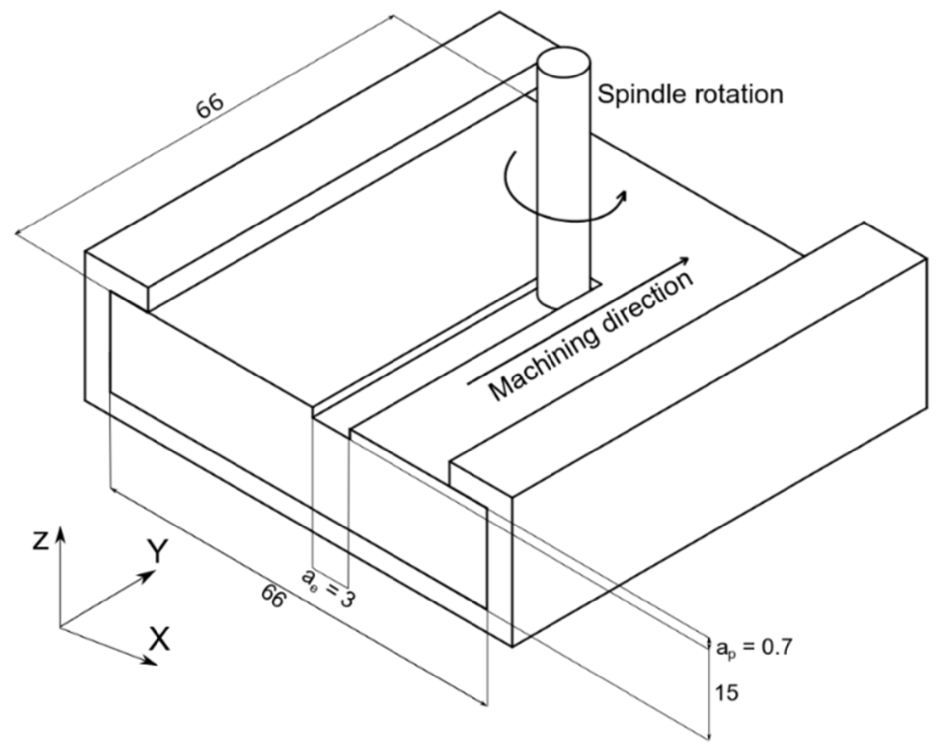
The axial depth of cut which is the immersion axial depth of the tool, ap;
-
The radial depth of cut which is the radial engagement of the tool in the material, ae.
Machining process parameters such as feed per tooth, cutting speed and depth of cut are substantially different for green ceramics compared to those for metals and sintered ceramic [25]. The softer nature of green ceramics dictates a less aggressive approach. Green machining requires a rigid fixture because of its low elastic modulus. Surface damages are generally chipping, pull-outs, grooving, and other artefacts. These damages can be reduced by modifying binder properties or machining parameters. Easler et al. [25] show that a threshold of cutting speed can be defined. Above the threshold, the cutting temperature reaches a critical value and so cutting tool material starts losing its hot hardness. Moreover, the ceramic particles are abrasive. Consequently, the tool wear must frequently be inspected to avoid an increase of bulk work piece temperature. In the green machining, the most popular tool materials are tungsten carbide and diamond [25].
Moreover, the cutting force associated to the cutting tool wear also has an impact on the surface finishing of the green part. Sanchez et al. suggest the presence of abrasive mechanism as the machining condition do not favor any other wear mechanism. [28].
Previous researches have therefore studied the influence of several process parameters such as the cutting speed and the feed rate, but no reliable method has been found to determine the optimal machining parameters and their impact on the surface quality in green machining.
In ductile materials, these cutting parameters may be determined through experiments. The tool-material coupling standard NF E66-520-5 assumes that the specific cutting energy is a global indicator of the quality of the cutting operation (e.g., surface quality, tool wear, repeatability). The specific cutting energy is the energy required to remove a material volume. This standard was applied with success on the Y-TZP material at the pre-sintering stage in a previous study [5]. This study shows that the toughening transformation is activated at the pre-sintering state and the behavior of material is similar to ductile material.
The aims of this paper are to apply the tool-material coupling standard method on the green Y-TZP to study the material behavior and the impact on surface quality, and to verify if this standard for ductile materials can be used to determine the cutting parameters.

2. Material and Methods

2.1. Material

The Belgian Ceramic Research Centre manufactures green blanks of black Y-TZP. To obtain green bodies, a fine yttria stabilized zirconia powder (3 mol% yttria–TZ-3Y-SE–Tosoh Corporation) was selected as the raw material. This powder has an actual particle size of around 100 nm and a specific surface area of 7 m2/g according to the supplier. To process the powder, an aqueous zirconia slurry was first prepared containing 60% of dry matter and Dolapix CE-64 (0.5% per mass of zirconia) as the dispersant. After milling for 2 h at natural pH in presence of large zirconia beads (5 mm), the slurry was then subsequently grinded in a laboratory agitator bead mills (Minicer–NETZSCH) in presence of 0.2 mm zirconia beads. Particle size distribution analysis (MALVERN) was performed at different grinding times to ensure that the maximum particle size was not exceeding 1 μm. A milling time of 4 h was found to be sufficient to mill a batch of slurry containing 1.2 kg of zirconia. 5 min before the end of grinding, three blanks are processed with a variation of binder percentage (1/2/3 wt%) of organic binder (Zusoplast—Zschimmer and Schwartz) was added in the slurry for strengthening the green bodies. After removing the grinding medias with a 500 µm mesh, each slurry was freeze dried for 24 h (Martin Christ) and then sieved at 100 µm to break the (poorly cohesive) agglomerates resulting from drying.
To obtain green-state workpieces, the powder was die-pressed at 20 MPa with a square mold having a side length of 70 mm. To ensure an optimal distribution of density within the samples, uniaxial compression was followed by an isostatic compaction at 195 MPa during 5 min.

2.2. Experimental Preparation

The experiments were performed on a 3-axis machine-tool. The maximum spindle speed is 35,000 RPM. The tool has a carbide cylindrical diameter of 3 mm and two flutes.
To be consistent with the standard, a set of experiments is carried out by only changing the cutting speed for each slot, while measuring the cutting power during the slotting operation. Table 1 shows the values that are chosen for the cutting speed. The other machining parameters are fixed at 0.7 mm for the axial depth of cut ap, 3 mm for the radial depth of cut ae and 0.048 mm/tooth for the feed per tooth fz.
Figure 1 shows the schematic assembly for the slotting tests.
The specific cutting energy Wc, i.e., the energy required to remove a unitary volume of material, is calculated from the measurements with the help of the following equation:
W c = P c Q = 1000   P c V f a p a e = 1000   P c f z   N   Z   a p a e
where Vf (mm/min) the feed rate which is the linear speed of the tool along its trajectory in the material, and Z the number of flutes.
The power is directly measured on the spindle, the cutting power, Pc, is obtained by the difference between idling power and working power. Figure 2 shows the evolution of power during a slotting test. The working power is the power generated by the machine when the tool removes material.
The roughness is measured for each slot with the multi-line roughness measurement tool of VK-X-Series Keyence with a cutoff λc of 0.7 mm. The roughness is the mean of 21 profiles spaced on the slotting width.

3. Results

3.1. Specific Cutting Energy

Figure 3 shows the evolution of the specific cutting energy (SCE) in relation to cutting speed for various percentages of binder. The specific cutting energy increases when the binder percentage increases. The curves follow a logarithmic tendency. The evolution of the curves is similar when the percentage of binder is higher than 2 wt%.

3.2. Surface Quality.

Figure 4 shows the evolution of the mean of arithmetic roughness (Ra) and the maximum height (Rz) in relation to cutting speed for each blank. Ra stays relatively constant around 2 µm for each cutting speed but also for each binder percentage. By contrast, the evolution of Rz is different according to wt% binder. In fact, the blank with 2 wt% has a Rz relatively constant around 13 µm for each cutting speed. By contrast, the evolution of the two others is not constant but it is stables in a short range between 139 and 179 m/min.

4. Discussion

The evolution of the specific cutting energy in green machining is not similar to the evolution of the specific cutting energy in pre-sintered (or ductile material) machining. In a pre-sintered block, a consolidation at the grain boundary maintains the grains between them with a sufficient percentage of metastable tetragonal phase to ensure the material ductility [5]. In the case of green machining, the specific cutting energy increases when the cutting speed increases following a logarithmic evolution. The material removal mechanism is therefore mainly due to the binder itself. The behavior of green ceramics could be assimilated to a non-Newtonian fluid behavior and more particularly to a pseudo-plastic fluid behavior [29]. The viscosity decreases when the cutting speed increases. Thereby, the rheological properties of the green body, which is composed of powders and binder, has an influence on the machinability [29].
In addition, the specific cutting energy is relatively low and shows that the material removal mechanism is mainly due to the tangent edges of the tool. Figure 5 shows the status of the tool after machining operations. Tool wear occurs on the tangential edges despite the low specific cutting energy because the ceramic particles held by the binder are strongly abrasive.
In the case of green machining, the material removal mechanism is due to the binder used. By increasing the percentage of binder, the forces generated to remove material become greater. Alias and Shapee also show the influence of wt% binder on the viscosity in green tapes ceramic in Low Temperature Co-fired Ceramic (LTCC ) technologies [30]. Nevertheless, the tendency seems similar after a threshold percentage. This shows that a minimum amount of binder is required into the system in order to have a pseudo-plastic behavior allowing repeatability at high cutting speeds. Table 2 shows the relative difference between two slotting tests with the same cutting parameters.
In fact, the deviation decreases when the cutting speed increases but only for the blanks with 2 and 3 wt% binder. Thereby, these cutting parameters allow to have a repeatable operation. These tendencies complement the literature review that mentions a need of a high cutting speed to machine a green body. In the case of a blank with 1 wt% binder, the polymer matrix is not sufficient to uniformly keep the ceramic powder compact.
Despite the variation of specific cutting energy, the arithmetic roughness (Ra) is relatively stable around 2 µm for each blank and whatever the cutting speed. It results that the binder does not influence the Ra even though the percentage by weight increases. By contrast, the other amplitude indicator is directly impacted. Indeed, at low cutting speed, Rz is different for each blank with an Rz value increasing when the wt% rises.
This phenomenon is essentially due to the risk of pullout that is more important at a low cutting speed. In fact, rubble clumps on the machined surface lead to an important variation of the Rz value at a low cutting speed. These rubble clumps caused by the material pullout are shown on Figure 6. After a threshold, the Rz value is relatively stable for each blank before varying slightly from 1 wt% and 3 wt%. This rubble clump is not evacuated by the rotation of the tool, and therefore it agglomerates on the green compact causing a degradation of the surface state which can directly impact the mechanical properties of the ceramic part.
Indeed, Wanga et al. [31] show that there is a correlation between surface roughness and flexure strength. The risk of crack propagation will occur at the bottom of the roughness profile valley. The cutting speed therefore has an influence on the risk of crack initiation and the evolution of the Rz value can be used as an indicator to show this risk of crack. In fact, this initiation of microcracks will already reduce their propagation during sintering operation and therefore a monoclinic phase will already be present on the final part. An important variation of this monoclinic phase after sintering will lead to a non-repeatability of the mechanical properties. It is therefore essential to keep the roughness Rz as stable as possible to guarantee process reliability.

5. Conclusions

The green body does not use the transformation toughening mechanism since there still has not been any sintering operation which allows to give mechanical properties (due to the phase change of the material). The machinability is influenced by the binder which gives a pseudo-plastic behavior to the green body which depends on the rotational speed of the tool.
Despite the non-ductile behavior of the material, the machining operations becomes repeatable at high cutting speeds. In fact, the relative deviation is reduced when the cutting speed is higher if the binder percentage is large enough. A minimum binder percentage must be used to ensure the uniformity of the compact. Above the minimum binder percentage, the tendencies are similar for the SCE evolution with a shift that increases when the binder is added to the system because the required forces are greater to remove the material volume.
The surface quality is similar whatever the binder percentage. Ra and Rz roughness values are steady when cutting speed rises despite the increase of specific cutting energy. The roughness is stable whatever the cutting speed and the binder percentage. A risk of pullout is detected at low cutting speed if the binder percentage is not adequate.
Finally, the machining quality depends on the rotational speed of the tool because the material removal mechanism is mainly due to the interaction of the material with the cutting edge of the tool. The tool must be in permanent contact with the material, avoiding shocks between the sharp edges and the material during each rotation of the tool. The cutting speed of the tool must be as high as possible to ensure sufficient and repeatable machining quality.

Author Contributions

Conceptualization, A.D. and F.D.; methodology, A.D.; formal analysis, A.D. and N.P.; investigation, E.R.-L.; resources, F.P.; writing—original draft preparation, A.D.; writing—review and editing, A.D., F.D. and E.R.-L.; supervision, F.D. and E.R.-L. All authors have read and agreed to the published version of the manuscript.

Funding

This research received no external funding

Acknowledgments

The research was conducted in cooperation with the Belgian Ceramic Research Centre and OPTEC laser systems.

Conflicts of Interest

The authors declare no conflict of interest.

References

  1. Lee, H.J.; Choi, N.; Yoon, E.-S.; Cho, I.-J. MEMS devices for drug delivery. Adv. Drug Deliv. Rev. 2018, 128, 132–147. [Google Scholar] [CrossRef] [PubMed]
  2. Sant, S.; Tao, S.L.; Fisher, O.Z.; Xu, Q.; Peppas, N.A.; Khademhosseini, A. Microfabrication technologies for oral drug delivery. Adv. Drug Deliv. Rev. 2011, 64, 496–507. [Google Scholar] [CrossRef] [PubMed] [Green Version]
  3. Yamamuro, T. Bioceramics. In Biomechanics and Biomaterials in Orthopedics; Poitout, D.G., Ed.; Springer: London, UK, 2004. [Google Scholar] [CrossRef]
  4. Adatia, N.D. Fracture Resistance and Surface Treatment of y-tzp Prepable Ceramic Abutments and Bars. Master’s Thesis, University of North Carolina at Chapel Hill, Chapel Hill, NC, USA, 2006. [Google Scholar]
  5. Demarbaix, A.; Rivière-Lorphèvre, E.; Ducobu, F.; Filippi, E.; Petit, F.; Preux, N. Behaviour of pre-sintered Y-TZP during machining operations: Determination of recommended cutting parameters. J. Manuf. Process. 2018, 32, 85–92. [Google Scholar] [CrossRef]
  6. Brog, J.-P.; Chanez, C.-L.; Crochet, A.; Fromm, K. Polymorphism, what it is and how to identify it: A systematic review. RSC Adv. 2013, 3, 16905. [Google Scholar] [CrossRef] [Green Version]
  7. Hannink, R.H.J.; Kelly, P.M.; Muddle, B.C. Transformation Toughening in Zirconia-Containing Ceramics. J. Am. Ceram. Soc. 2004, 83, 461–487. [Google Scholar] [CrossRef]
  8. Deville, S.; Chevalier, J. Martensitic Relief Observation by Atomic Force Microscopyin. J. Am. Ceram. Soc. 2003, 27, 2225–2227. [Google Scholar] [CrossRef]
  9. Fook, P.; Berger, D.; Riemer, O.; Karpuschewski, B. Structuring of Bioceramics by Micro-Grinding for Dental Implant Applications. Micromachines 2019, 10, 312. [Google Scholar] [CrossRef] [Green Version]
  10. Poulet, A. Etude du comportement à la rupture de céramiques de type ZrO2 CeO2 monolithiques et composites renforcés par une phase secondaire d’alumine. Ph.D. Thesis, University of Mons, Mons, Belgium, 1998. [Google Scholar]
  11. Leu, M.C.; Delli, P.; Walker, M.P. Digital Design and Fabrication in Dentistry. In Bio-Materials and Prototyping Applications in Medicine; Bártolo, P., Bidanda, B., Eds.; Springer: Boston, MA, USA, 2008. [Google Scholar] [CrossRef]
  12. Sanon, C. Lumière sur la zircone 3Y-TZP utilisée en implantologie orale: Étude de la relation entre la microstructure et la durabilité. Ph.D. Thesis, INSA Lyon, Lyon, France, 2015. [Google Scholar]
  13. Demarbaix, A.; Rivière-Lorphèvre, R.; Ducobu, F.; Filippi, E.; Petit, F. The Hybrid Machining of Ceramic: The choice of production stage. In Proceeding of the International Conference & Exhibition EUSPEN, Hanover, Germany, 30 May–1 June 2017. [Google Scholar]
  14. Petit, F. Green Machining of Ceramics. Ref. Modul. Mater. Sci. Mater. Eng. 2019. [Google Scholar] [CrossRef]
  15. Ferraris, E.; Vleugels, J.; Guo, Y.; Bourell, D.; Kruth, J.-P.; Lauwers, B. Shaping of engineering ceramics by electro, chemical and physical processes. CIRP Ann. 2016, 65, 761–784. [Google Scholar] [CrossRef]
  16. Ito, Y.; Kizaki, T.; Fujii, T.; Yuasa, Y.; Sugita, N. Precision Machining of Yttria-stabilized Tetragonal Zirconia Polycrystal by High-speed Milling. Int. J. Autom. Technol. 2017, 11, 862–868. [Google Scholar] [CrossRef]
  17. Arif, M.; Rahman, M.; San, W.Y. Analytical model to determine the critical conditions for the modes of material removal in the milling process of brittle material. J. Mater. Process. Technol. 2012, 212, 1925–1933. [Google Scholar] [CrossRef]
  18. Li, R.W.K.; Chow, T.W.; Matinlinna, J.P. Ceramic dental biomaterials and CAD/CAM technology: State of the art. J. Prosthodont. Res. 2014, 58, 208–216. [Google Scholar] [CrossRef] [PubMed] [Green Version]
  19. Mitov, G.; Gessner, J.; Lohbauer, U.; Woll, K.; Muecklich, F.; Pospiech, P. Subcritical crack growth behavior and life data analysis of two types of dental Y-TZP ceramics. Dent. Mater. 2011, 27, 684–691. [Google Scholar] [CrossRef] [PubMed]
  20. Luthardt, R.G.; Holzhüter, M.S.; Rudolph, H.; Herold, V.; Walter, M.H. CAD/CAM-machining effects on Y-TZP zirconia. Dent. Mater. 2004, 20, 655–662. [Google Scholar] [CrossRef]
  21. Studart, A.R.; Filser, F.; Kocher, P.; Gauckler, L.J. Fatigue of zirconia under cyclic loading in water and its implications for the design of dental bridges. Dent. Mater. 2007, 23, 106–114. [Google Scholar] [CrossRef]
  22. Filser, F.T. Direct Ceramic Machining of Ceramic Dental Restorations. Ph.D. Thesis, Swiss Federal Institute of Technology Zurich, Zurich, Switzerland, 2001. [Google Scholar]
  23. Onler, R.; Korkmaz, E.; Kate, K.; Chinn, R.; Atre, S.V.; Ozdoganlar, O.B. Green micromachining of ceramics using tungsten carbide micro-endmills. J. Mater. Process. Technol. 2019, 267, 268–279. [Google Scholar] [CrossRef]
  24. Dhara, S.; Su, B. Green Machining to Net Shape Alumina Ceramics Prepared Using Different Processing Routes. Int. J. Appl. Ceram. Technol. 2005, 2, 262–270. [Google Scholar] [CrossRef]
  25. Easler, T.; Khalfalla, Y.; Benyounis, K. Green Machining. Ref. Modul. Mater. Eng. 2016. [Google Scholar] [CrossRef]
  26. Helu, M.; Behmann, B.; Meier, H.; Dornfeld, D.; Lanza, G.; Schulze, V. Impact of green machining strategies on achieved surface quality. CIRP Ann. 2012, 61, 55–58. [Google Scholar] [CrossRef] [Green Version]
  27. Association Française de Normalisation AFNOR (1999)—NF E 66-520-5 (E). Working Zones of Cutting Tools—Part 5: Application to Milling Technology; AFNOR Group: La Plaine Saint-Denis, France, 1999. [Google Scholar]
  28. Sanchez, L.; Bukvic, G.; Fiocchi, A.A.; Fortulan, C.A. Allowance removal from green pieces as a method for improvement surface quality of advanced ceramics. J. Clean. Prod. 2018, 186, 10–21. [Google Scholar] [CrossRef] [Green Version]
  29. Kazemian, S.; Prasad, A.; Huat, B. Review of Newtonian and non-Newtonian fluids behaviour in the context of grouts. Geotech. Asp. Undergr. Constr. Soft Ground 2012, 321–326. [Google Scholar] [CrossRef]
  30. Alias, R.; Mohd, S. Rheological Behaviors and Their Correlation with Printing Performance of Silver Paste for LTCC Tape. Rheology 2012. [Google Scholar] [CrossRef] [Green Version]
  31. Wang, H.; Aboushelib, M.; Feilzer, A.J. Strength influencing variables on CAD/CAM zirconia frameworks. Dent. Mater. 2008, 24, 633–638. [Google Scholar] [CrossRef] [PubMed]
Figure 1. Schematic assembly for the slotting tests dimensions in mm.
Jmmp 04 00050 g001
Figure 2. Evolution of power during a slotting test.
Jmmp 04 00050 g002
Figure 3. Specific cutting energy in relation with the cutting speed for various percentages of binder
Jmmp 04 00050 g003
Figure 4. Evolution of roughness in relation with cutting speed for various percentages of binder.
Jmmp 04 00050 g004
Figure 5. Tool wear after machining operations.
Jmmp 04 00050 g005
Figure 6. Rubble clumps caused by the material pullout (Vc = 98 m/min in the green body with 3 wt%).
Jmmp 04 00050 g006
Table 1. Parameters for the experimental plan.
Variation of Cutting Speed Vc (m/min)
98124139152179193208221236
Table 2. Relative deviation of specific cutting energy between two slotting tests with the same cutting parameters.
Vc (m/min)Relative Difference of Deviation
1 wt%2 wt%3 wt%
980.760.540.50
1240.640.580.45
1390.540.510.39
1520.300.430.34
1790.650.380.28
1930.590.310.31
2080.620.200.23
2210.620.120.12
236/0.050.08

