1. Introduction
The investigation of the frictional behavior under conditions comparable to those in the tool/chip and the tool/workpiece contact zone has been the scope of several researchers. To determine the occurring friction between the tribo-partners in machining, different approaches have been followed in the scientific literature. One major issue regarding the investigation of acting mechanisms of the cutting fluid in machining is that different contact conditions occur in machining. In 1963, Zorev described the contact conditions, which led to the development of a friction model that is still one of the most widely used to describe the contact conditions. The friction on the rake face, respectively in the tool chip contact zone, is characterized by static friction due to adhesive bonds between the chip and the tool on the one hand and by sliding friction between the tool and the chip after a certain contact length on the other hand [
1].
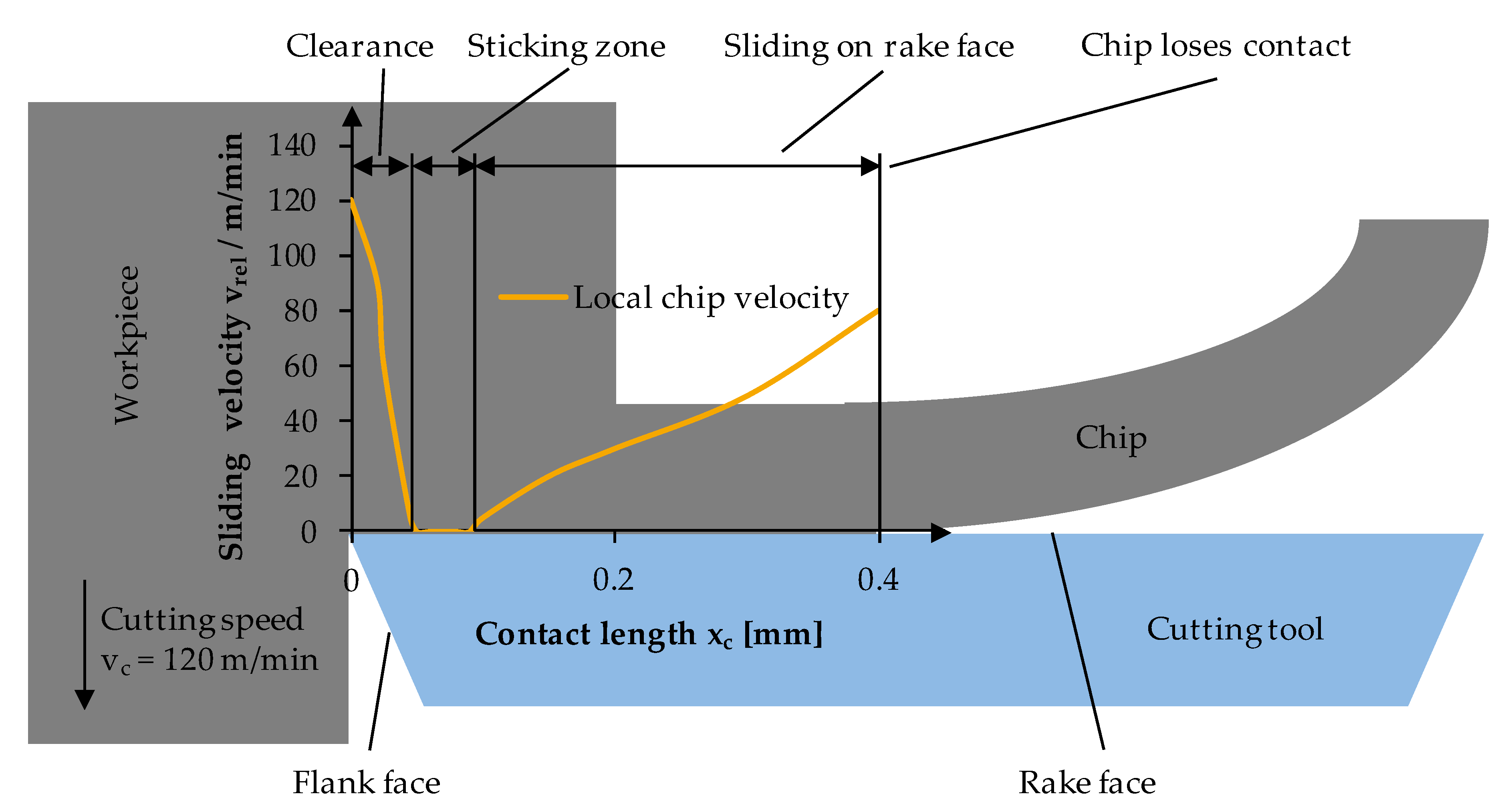
Bonnet described the different friction parts on the rake face in the machining of steel that are shown in
Figure 1 [
2]. Directly behind the cutting edge, the chip velocity rapidly shrinks to zero. For a certain contact length, the chip material has a sliding velocity of zero, which starts to increase for the rest of the tool–chip interface, before the chip loses contact to the tool. Subsequently, a constant friction coefficient over the whole tool–chip contact length, as used for many simulations, cannot be considered practical.
The contact stresses
σn in the area close to the cutting edge on the rake face can reach more than 2000 MPa [
3]. Therefore, the contact reaches 100% in metal cutting processes, which contributes to the perception that cutting fluids can act in the sliding friction zone, but are not able to penetrate into the sticking friction zone. Due to this, the focus of most tribometer experiments is the investigation of the action of cutting fluids under sliding friction. Other studies investigated the frictional aspects from a theoretical point, e.g., by using slip-line models [
4,
5,
6]. Since some of the approaches have the drawback of overlapping effects that are difficult to differentiate, the frictional phenomena have been investigated by utilizing analogy tests to determine the friction coefficient
under specific conditions [
7].
Real tribological systems, such as those in the machining process, are usually very complex and difficult to investigate at great expense. The reasons for this are the overlapping friction and wear mechanisms in the real system, which sometimes reinforce or weaken each other. For this reason, standardized tribometers are used to investigate tribological systems as an abstraction of real systems [
8]. In total, the tribological contact is simulated in different degrees of abstraction in more than 100 different tribometers. The ‘standard test method’ in tribology is the pin-on-disc tribometer, in which a counter body is applied to a rotating base body with a defined normal force on adjustable radii [
9]. The coefficient of friction µ can be calculated from the relation of friction and normal force. However, since the tribological conditions are far from those encountered in conventional tribological tests, conventional tribological tests cannot be used when determining the frictional behavior in the machining processes [
10].
In order to overcome the limitations, especially in terms of the transferability of the results from conventional tribometrical tests to the domain of machining, various tribometers have been developed. Olson et al. proposed one of the first variants in 1989 [
11]. The design is similar to a longitudinal face turning process, in which the end face of a tube is machined. Shortly after the tool, a pin is attached, which rubs over a constantly renewed surface. Due to the low stiffness of this concept, the required contact pressures cannot be achieved. With this test setup, automated long-term tests are only possible to a limited extent, since the pipe must be changed.
In 1991, Hedeqvist and Olsson presented a further test bench [
12]. In this variant, a cylindrical pin follows a helical path along a rotating shaft. The contact surface is not the front side of the pin, but the circumferential surface. After the pin has travelled the entire length of the shaft, the surface can be renewed by a longitudinal circular turning process and the test can be continued. This enables long-term tests to be carried out.
Grzesik published another proposal in which a linear frictional contact is established between the basic body and the counter body [
13]. He also did not achieve the usual contact pressure, which occurs in machining, and, in addition, worked with a non-renewable surface of the counter body.
To solve the problem of low contact pressures, Claudin used a design in which the spherical end of the pin is pressed by a pneumatic cylinder onto a shaft, which is clamped in a lathe [
14]. Similar to Hedenqvist, the pin moves in translational direction to the shaft. In addition, a cutting tool has been integrated to produce a new surface, which is subsequently improved in a grinding step. With this design, it is possible to generate a maximum contact pressure of 3 GPa at a maximum speed of 200 m/min.
Zemzemi combined the test stands of Claudin and Olsson [
15]. Similar to Olsson, a tube is used as the rotating counter body, the pin rubs against its front side. The same equipment as for Claudin guarantees the contact pressure. Due to this modified design, it is possible to increase the maximum friction speed considerably.
Ozlu used a simpler experimental setup, which compared the friction parameters of the orthogonal rotation process of a tube with those from a pin-on-disc test [
16]. For the tribological test, the counter body was clamped in a lathe. For the material/cutting material pairings selected by the author (C50/WC and C50/coated WC), it was shown that the different contact pressures do not have any significant influence on the coefficient of friction.
Brocail used a conventional tensile testing machine [
17] for the test bench. A rod, which is fixed to the machine table, serves as the base body, while a ball, which is pressed against the cylindrical surface, is moved upwards. The rod is heated up to 1250 °C, the ball to 300 °C. With this configuration, it is possible to reproduce the conditions during machining well, except for the relative velocity. A fresh surface cannot be guaranteed with this configuration neither are long-term tests practical.
Trauth et al. developed a friction test bench in 2017, which can be regarded as a pin-on-cylinder tribometer with an axial feed [
18]. Compared to conventional tribometers, such as the pin-on-disc tribometer, the test setup is designed to ensure that the tool rubs over an unmachined workpiece surface with each revolution. A lathe realizes the rotary movement of the workpiece in the form of a shaft and the translatory movement of the workpiece (feed). A hydraulic actuator applies the normal force of the tool on the workpiece.
However, the developed approaches to determine the frictional interactions at the tool–chip interface have two inherent drawbacks. One drawback of the approaches are the occurring loads and the transferability of the results to the machining process. Partly, the achievable relative velocities are below the relative velocities between tool and chip and the normal pressures are far away from those occurring in the machining process. Furthermore, the approaches investigated solely dry friction conditions and neglected therefore the influence of cutting fluid on the frictional interactions.
An approach that is capable to reproduce the mechanical contact conditions of the cutting process has been developed by Klocke et al. [
7,
19]. In their frictional set-up, an orthogonal cutting process on a lathe has been modified in such a way that the cutting tool insert has an extremely negative rake angle [
6]. Due to the negative rake angle, the chip formation process was suppressed, wherefore the process can be considered as a high-speed deformation process. The experimental set-up has to be considered as a closed tribo-system, since the tool rubs over the same surface after one rotation of the workpiece. To realize an open tribo-system, the set-up of an orthogonal friction test has been realized on a broaching machine tool [
19]. The set-up let to the development of a temperature-dependent friction model and has further been used in several publications [
20,
21,
22].
However, most of the research conducted so far did not investigate the influence of the cutting fluid in metal cutting, nor in interrupted cutting. Sterle et al. investigated in their study the influence of different cutting fluids and cooling strategies for a wide range of relative velocities on the frictional behavior using an open tribometer [
23]. The investigated cutting fluids and cooling strategies embraced dry machining, coolant, emulsion, liquid CO
2 (LCO
2), minimum quantity lubrication (MQL), MQL+LCO
2, and solid lubricant MoS
2. In their experiments, an exponentially decreasing trend was identified when increasing the relative velocity for dry cutting. In case of using emulsion, a large initial increase of the friction coefficient was observed when increasing the relative velocity, which decreased slightly for higher relative velocities. The decreasing trend of the friction coefficient for higher relative velocities was due to the self-lubrication with higher temperatures.
With regards to the focused high-pressure cutting fluid supply, Machado and Wallbank described the acting mechanisms of the focused high-pressure cutting fluid supply from the rake face, which is the most common application way of this technology [
24]. In their model, they utilized the two-zone friction model by Zorev [
1]. Therefore, they described the stress distribution in the continuous contact on the rake face for flood cooling and high-pressure cutting fluid supply. The contact length
lch was reduced by the cutting fluid jet force
Fjet. Therewith, the focused cutting fluid jet marginally reduced the sticking zone by mechanical action, whereas the sliding zone was reduced decisively by mechanical as well as lubricating effects. Interestingly, no significant changes of the cutting force
Fc occurred [
24]. The results of Machado and Wallbank, which were gathered when machining Ti-6Al-4V and Inconel 701, are supported by many other researchers for other materials, such as stainless steel X2CrNiMo 22-5 and X2CrNiMoN 17 14 3, bearing steel 100Cr6 and many others [
25,
26,
27].
Kaminski and Alvelid have shown that under machining conditions with industrial relevance, pressure levels over
p = 700 bar are necessary to change the conditions of friction significantly in order to lower the process forces. Ref. [
28] Such high pressure levels are achievable in laboratory scale, but not in industrial processes, where the supply pressure of most machine tools is about
p = 80 bar and in some exceptional cases up to
p = 300 bar. Therefore, it can be concluded that for investigations of the frictional conditions under high-pressure cutting fluid supply, the relevance of sliding friction dominates in comparison to sticking friction.
Summarizing the state of the art, the existing tribometers partly do not represent the contact conditions of machining with interrupted cuts, such as the milling process. Furthermore, most of experimental investigations focus on dry friction and do not consider the influence of cutting fluid. Therefore, a novel experimental set-up is demonstrated within this paper to investigate the influence of the application of cutting fluid on the frictional conditions in interrupted machining, such as the milling process. Hence, the question if the interrupted cut enables the application of cutting fluid when the cutting edge is not engaged in order to ensure a sufficient lubrication during the contact time needs to be answered. Moreover, it is unknown, whether higher cutting fluid supply pressures are beneficial in interrupted cuts on the coefficient of friction in the sliding zone as it is the case in continuous operations. Finally, the necessary volumetric flow rates and pressure levels are necessary to be elaborated together with a suitable impact point of the cutting fluid jet.
Therefore, a test bench has been developed, which is capable to reproduce the conditions of metal cutting in terms of the relative velocities and the applied thermo-mechanical loads as well as capable to investigate the influence of the cutting fluid. The experimental set-up has been built on a conventional lathe with a workpiece having grooves in axial direction to reproduce the conditions of interrupted cutting. The frictional tests have been conducted by varying the setting parameters fluid pressure, volumetric flow rate, relative velocity, normal force, and cutting fluid impact point. The investigations have been conducted for two different workpiece materials. The following chapters are highlighting firstly the experimental boundary conditions of the conducted tests, followed by the experimental results regarding the investigated influencing parameters. In
Section 4, a discussion of the experimental results will be given, followed by the conclusions of this work.
3. Results
This chapter highlights the experimental results of the conducted friction experiments. Therefore, the chapter is divided according to the analyzed influencing parameters, starting with the relative velocity and followed by the contact pressure, cutting fluid supply pressure, volumetric flow rate, and cutting fluid impact point.
3.1. Influence of the Relative Velocity
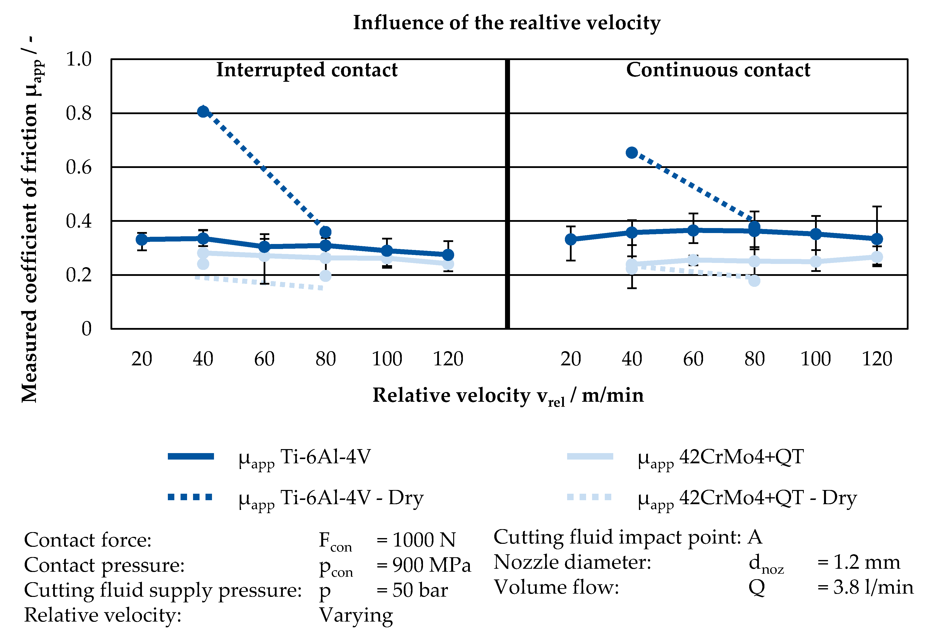
To investigate the influence of the relative velocity between the contact partners on the frictional conditions, the relative velocity has been varied in six (Ti-6Al-4V) and five (42CrMo4+QT) stages from 20 m/min (Ti-6Al-4V) respective 40 m/min (42CrMo4+QT) to 120 m/min, being representative for the chip velocity in metal cutting operations. The results of the conducted experiments are illustrated in
Figure 5, showing the coefficient of friction (CF) over the investigated relative velocities. The left side of the diagram shows the interrupted contact, whereas the right side shows the continuous contact. During the experiments, the reference condition of cutting fluid supply has been used with a cutting fluid pressure of
p = 50 bar and a volumetric flow rate of
Q = 3.8 L/min.
As it can be seen in
Figure 5, no distinct influence of the relative velocity on the measured CF can be determined for the investigated condition of cutting fluid supply. For the test conditions of interrupted contact, the CF is around
= 0.3 with slightly lower CF for 42CrMo4+QT. This is in agreement with previous publications, showing an asymptotical CF for high relative velocities [
23]. However, the almost constant CF for the investigated relative velocities is attributed to the wetting of the tool due to the grooves in the workpiece enabling a sufficient lubrication of the contact zone.
When comparing the results in terms of the CF between the two contact conditions of interrupted and continuous contact, the CF appears to be larger for the continuous contact for Ti-6Al-4V and slightly larger for 42CrMo4+QT. The differences for the Ti-6Al-4V alloy can be explained by the better lubrication of the contact zone between tool and workpiece, which is beneficial for this material. In contrast, the slightly lower CF for the 42CrMo4+QT can be attributed to expected higher temperatures in case of the continuous contact, resulting in a higher self-lubrication of the material. This explanation is supported by the conducted friction test, where no cutting fluid was supplied. For these experiments, the determined CF was in the magnitude or lower than their counterparts, where cutting fluid has been supplied.
For the dry friction experiments in combination with Ti-6Al-4V a significant decrease of the CF can be observed within the domain of relative velocities from 40 to 80 m/min. Due to these observations, a strong beneficial influence of cutting fluid can be identified for machining of Ti-6Al-4V, especially for lower relative velocities.
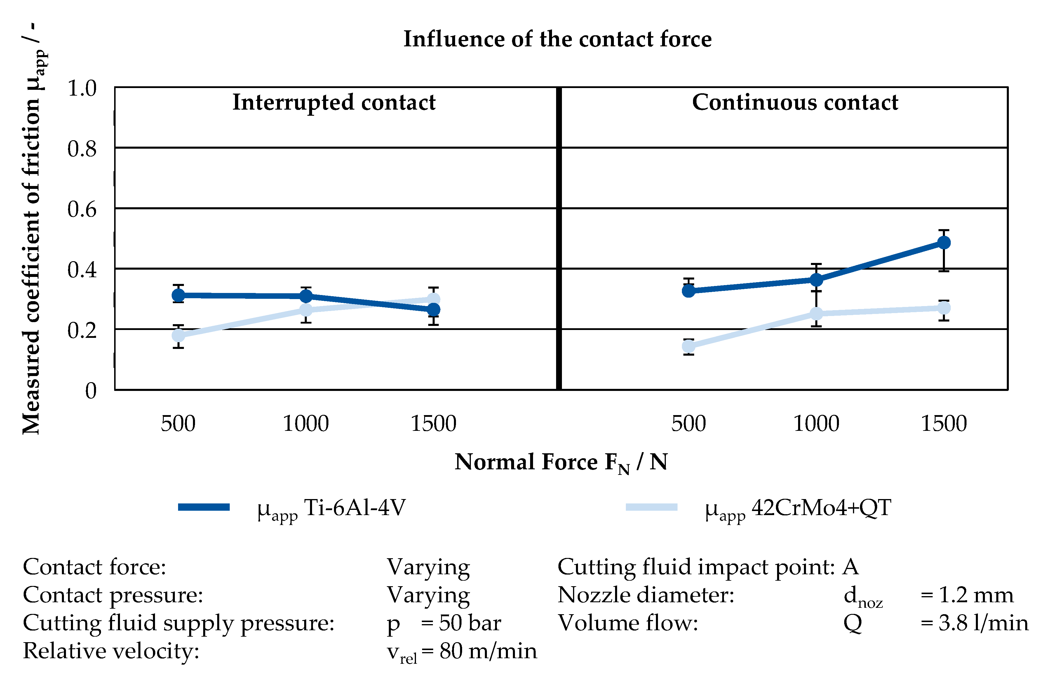
3.2. Influence of the Normal Force
To investigate the influence of the contact pressure between the tool and workpiece on the friction, the normal force has been varied in three stages from 500 N to 1500 N. The feed has been increased until the predefined contact force was reached. The results of the conducted experiments are shown for both investigated alloys in
Figure 6. For Ti-6Al-4V in the interrupted contact, a slight decrease can be observed with increasing normal force. It is expected that the thermal softening effect of the workpiece material due to the higher plastic deformation causes the decreasing trend of the CF. However, for the interrupted contact, the experimental results show that a sufficient wetting of the surface due to the grooves is still given and that the CF is, therefore, not affected to a large extent. For the 42CrMo4, the influence of the increased normal force is oppositional to the Ti-6Al-4V alloy. When increasing the normal force, an increase of the CF can be observed for 42CrMo4+QT. This trend is deducted to the low frictional effect of the cutting fluid for 42CrMo4+QT, which has been observed for the previous experiments as well. Higher normal forces result in this case in higher normal pressures, which cannot be compensated by the cutting fluid.
The beneficial effect of the cutting fluid for Ti-6Al-4V alloy is reinforced when analyzing the experimental results of the continuous cut. In this case, an increase of the CF can be observed for higher normal forces. These results can be explained by an insufficient wetting of the contact region by the cutting fluid. In the case of the interrupted contact, the cutting fluid was still brought into the contact zone due to the grooves. For continuous contact, the normal pressures are too high, wherefore the lubrication of the contact region cannot be realized sufficiently anymore.
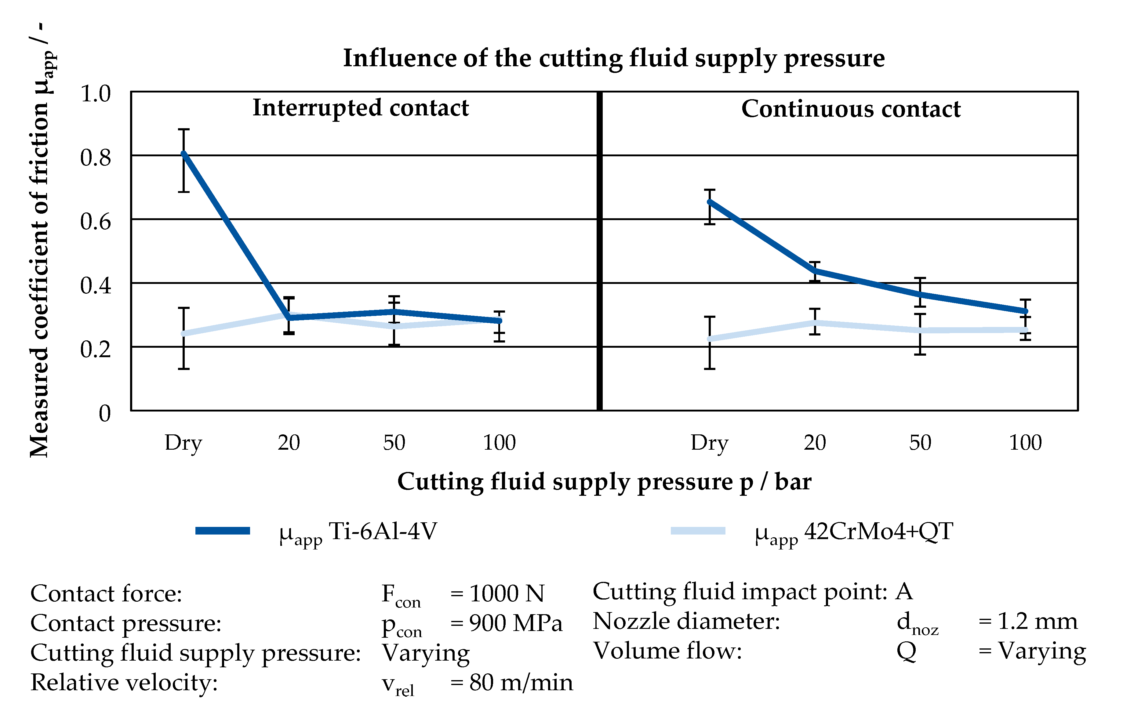
3.3. Influence of the Cutting Fluid Supply Pressure
The cutting fluid supply pressure was set directly at the high-pressure pump. Three different pressures of
p = 20 bar,
p = 50 bar, and
p = 100 bar were used.
Figure 7 shows the influence of the cutting fluid supply pressure on the coefficient of friction.
For the interrupted contact, the supply pressure has no noticeable influence on the friction. The CF is about = 0.3 for both materials. With an increase of the supply pressure, no significant variation of the CF is observable. This indicates that the intermitted contact enables a sufficient wetting of the contact surfaces. Moreover, the agents of the cutting fluid that is applied during the interruption act lubricating during the entire contact time. The contact times are so short that the agents are drawn out of the cutting zone, since the CF is almost constant during the contact time. On the other hand, during the continuous contact, the CF decreases with higher supply pressures when using the workpiece material Ti-6Al-4V. Apparently, higher supply pressures lead to a better supply of cutting fluid in the contact zone and, thus, to a reduction of friction. The CF decreases from the value of = 0.44 (p = 20 bar) to = 0.31 (p = 100 bar), which is equal to a decrease of approximately 30%. In contrast to this, the CF when machining 42CrMo4+QT shows no significant influence by the supply pressure, neither for continuous, nor for interrupted contact. The CF is constantly at about = 0.3 for all pressure stages. The assumed reason is the self-lubricating effect of the alloying element sulfur (<0.035%). This assumption becomes more evident when comparing the experiments under dry conditions with the experiments under cutting fluid supply. The CF in the interrupted cut was more than twice as high when comparing the dry experiment to the experiment with a supply pressure of p = 20 bar with the workpiece material Ti-6Al-4V, which has no self-lubricating alloying elements. When using 42CrMo4+QT, the CF was lower in the interrupted cut even when comparing the dry experiment to the experiment with a supply pressure of p = 20 bar. This can be traced back to the thermal softening effect during dry machining of 42CrMo4+QT. With an increasing workpiece temperature, the tensile strength decreases. Hence, the normal force exerted on the cutting tool decreases, which consequently leads to a lower CF.
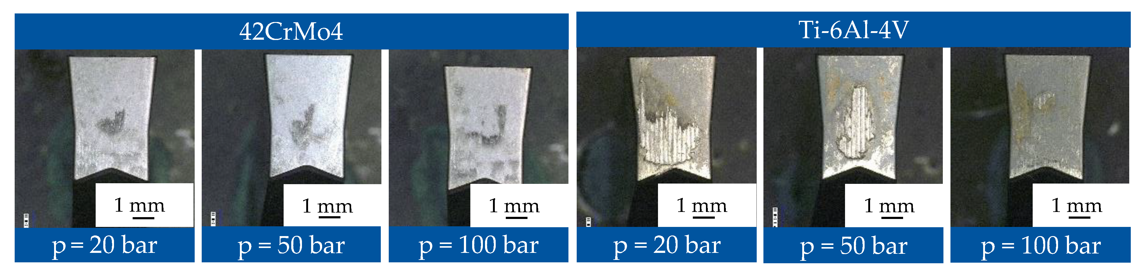
In terms of wear of the cutting tool inserts, an increasing supply pressure had a highly wear reducing effect in the experiments with the workpiece material Ti-6Al-4V,
Figure 8. Opposed to this, the effect of the cutting fluid supply pressure on tool wear with the workpiece material 42CrMo4+QT was negligible. This supports the hypothesis that Ti-6Al-4V demands high lubrication properties on the cutting fluid supply strategy, whereas 42CrMo4+QT has sufficient self-lubrication properties under the examined parameter range.
3.4. Influence of the Volumetric Flow Rate
If an incompressible fluid, like the utilized cutting fluid, flows through a tube with a defined cross section
A, the mass flow—and as a result, the volumetric flow rate
Q—stays constant according to the equation of continuity, Equation (1) [
41].
By transposing the
Bernoulli’s equation, the jet velocity can be expressed according to Equation (2), and depends therefore on the pressure difference between ambient pressure and supply pressure [
41].
When inserting Equation (2) in Equation (1), it can be stated that a change in volumetric flow rate can be achieved with a constant supply pressure by the change of the coolant nozzle diameter, which is expressed in Equation (3) by the cross section
A [
41].
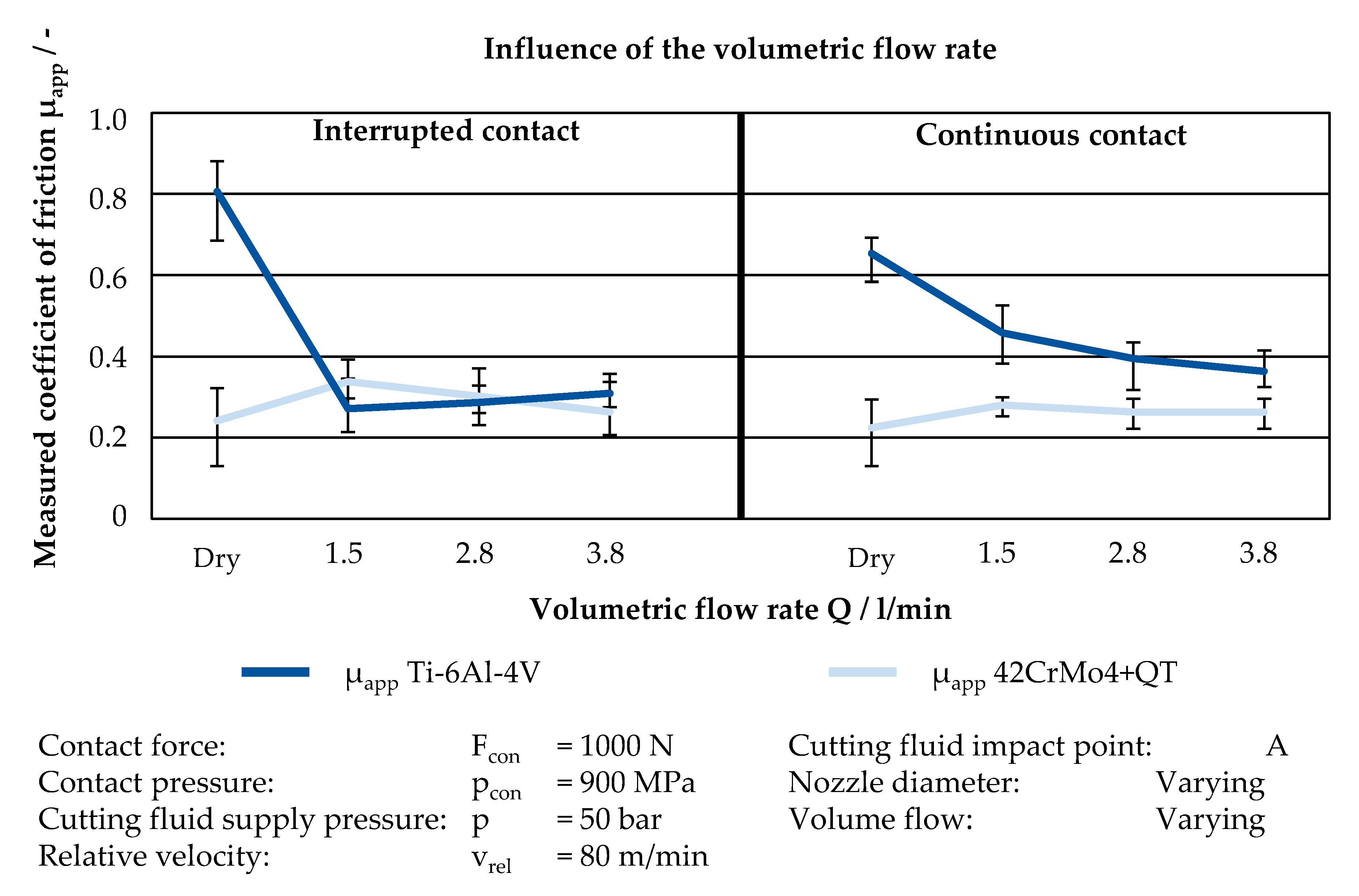
The volumetric flow rate was therefore varied via the nozzle diameter dnoz under a constant cutting fluid supply pressure of p = 50 bar during the experiments. The resulting volumetric flow rates were Q = 1.5 L/min with a nozzle diameter d = 0.8 mm, Q = 2.8 L/min with a nozzle diameter d = 1.0 mm and Q = 2.8 L/min with a nozzle diameter d = 1.2 mm.
The measured data from the friction experiments are shown in
Figure 9. Analogous to the results of the influence of the supply pressure, an increase of the volumetric flow rate did not lead to a noticeable difference in the CF for both materials during the interrupted contact. In the continuous contact, the CF decreased with an increasing volumetric flow rate when using titanium as workpiece material. The CF decreased from about
µapp = 0.46 (
Q = 1.5 L/min) to
µapp = 0.36 (
Q = 3.8 L/min), which equals a decrease of approximately 22%.
When machining 42CrMo4+QT, the self-lubricating effect occurred and, consequently, no influence of higher volumetric flow rates on the CF was traceable. Moreover, the assumed thermal softening leads to a lower CF when comparing dry to wet machining, also under varying volumetric flow rates.
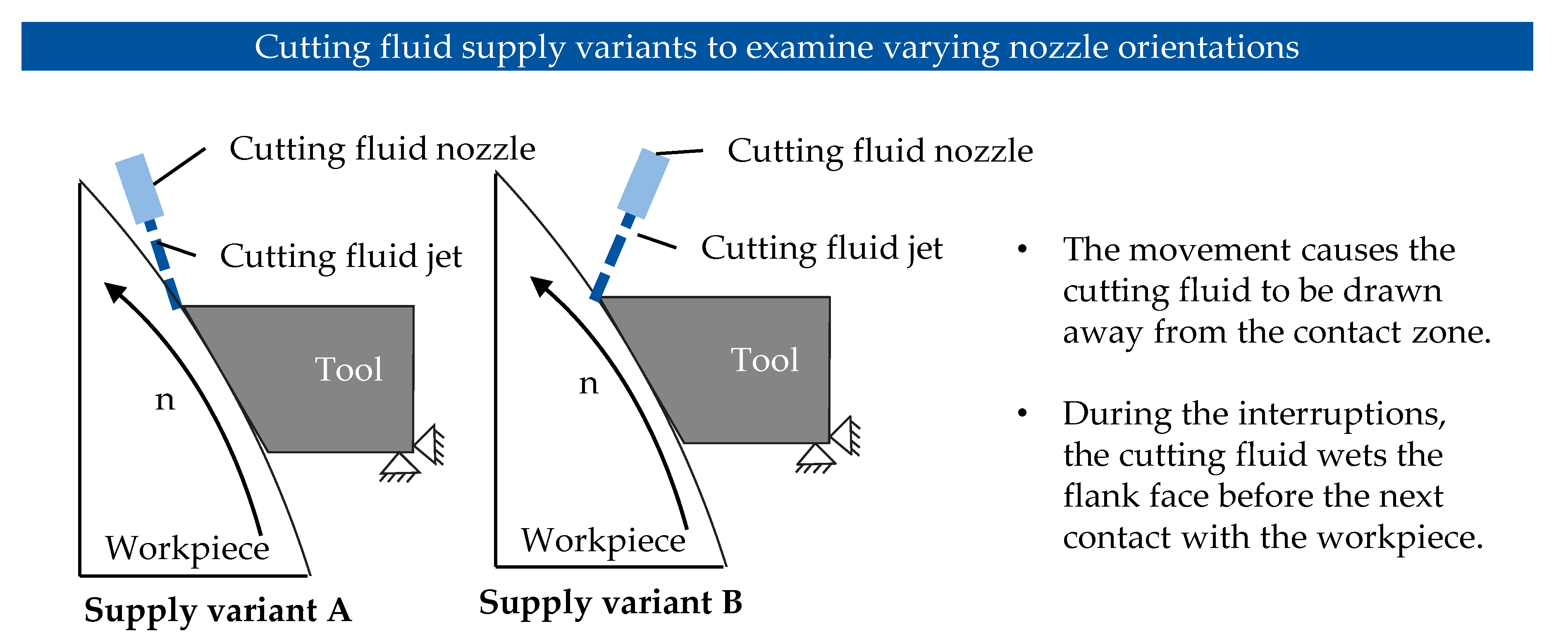
3.5. Influence of the Cutting Fluid Impact Point
The two investigated cutting fluid impact points, as a result of a varying impact angle, are illustrated in
Figure 10. The first supply impact point (A) correspondents to the supply of cutting fluid into the contact zone between chip and tool. The impact point (B) is set directly in front of the flank face to show the effect when the cutting fluid impacts in front of the wedge between tool and emerging chip, which may lead to atomization and a lack of penetrability into the contact zone.
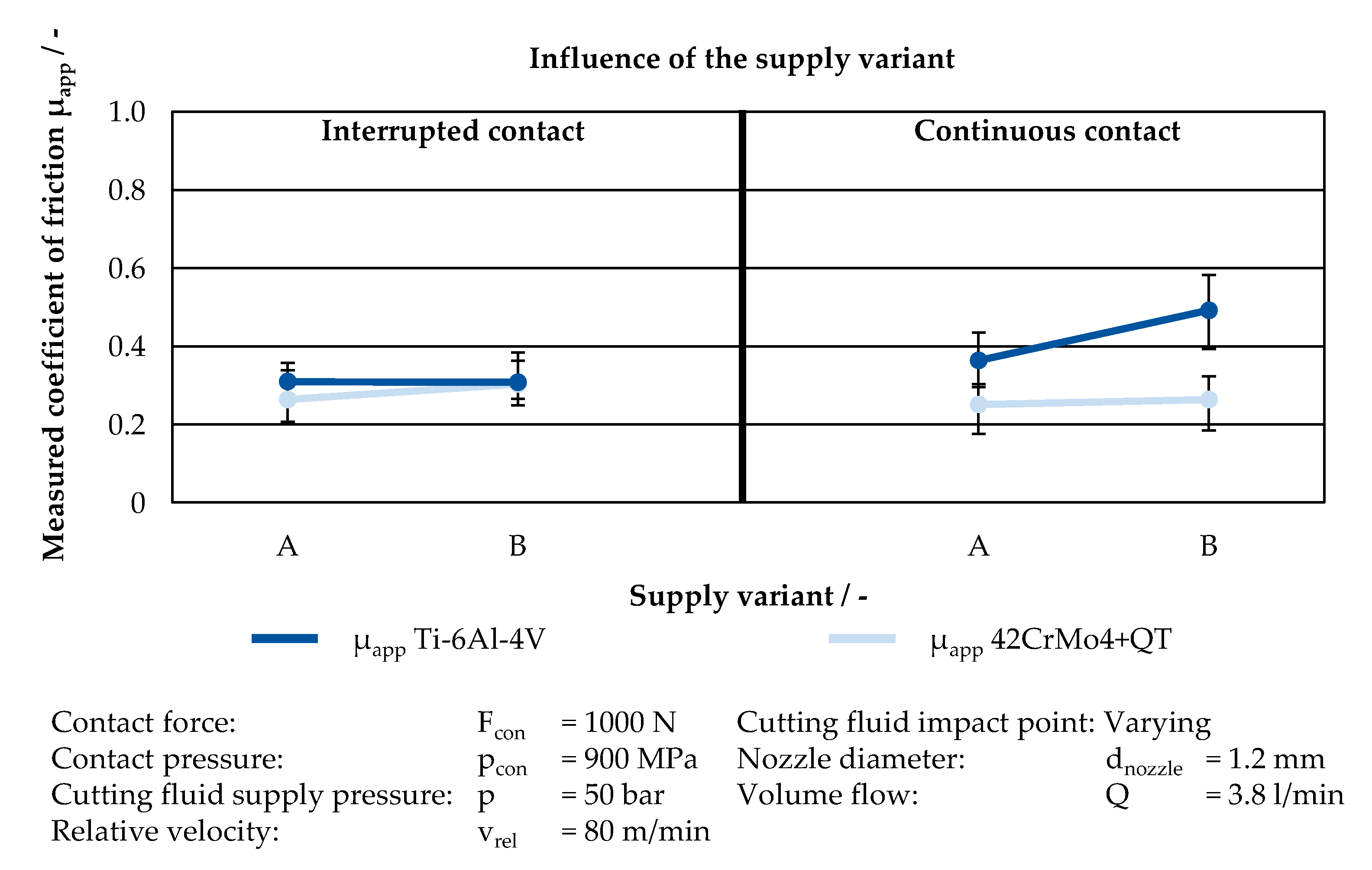
The CF in dependency of the cutting fluid impact point are shown in
Figure 11. While the impact point has no considerable influence on the CF for the interrupted contact, the influence on the CF for Ti-6Al-4V under continuous contact conditions is distinct. The CF increased from
µapp = 0.39 by about 26% to
µapp = 0.49. The vast influence of the cutting fluid impact point on the CF when using titanium indicates that the cutting fluid is not able to penetrate the contact zone or is drawn away before the agents can act in the contact zone. According to the previous examinations, the cutting fluid has nearly no impact on the friction with 42CrMo4+QT as workpiece material. Therefore, it can be said that for the CF of 42CrMo4+QT it is of subordinate importance if and where the cutting fluid is applied, because of the self-lubrication effect of the material. However, the cutting fluid impact point has a vast influence on the CF when machining titanium. In the interrupted contact, the cutting fluid is able to wet the contact zone, because of the interruption by the grooves in the workpiece. On the other hand, in continuous contact, the friction rapidly increases once the cutting fluid is drawn away from the contact zone. As a result, the CF in continuous conditions correspondents approximately to the CF for the dry experiments.
4. Discussion
The conducted experiments on the two alloys under investigation revealed distinct differences between the two materials regarding their frictional behavior under metal cutting conditions. Based on the investigated influencing factors, a self-lubricating effect has been observed for 42CrMo4+QT resulting in an overall lower coefficient of friction in comparison to the coefficient of friction of Ti-6Al-4V. The self-lubricant effect of the 42CrMo4+QT can be attributed to the alloying element sulfur, which has a content of lower than 0.035% in 42CrMo4+QT. The observed effect becomes more evident, when comparing the conducted experiments under dry conditions with those where cutting fluid has been supplied to the contact area. For these experiments, no distinct influence of the cutting fluid supply on the coefficient of friction of 42CrMo4+QT over a wide range of relative velocities can be observed.
In contrast to these observations on 42CrMo4+QT, the supply of the utilized cutting fluid had a major influence of the coefficient of friction for Ti-6Al-4V. For dry contact conditions, the coefficient of friction was significantly higher than the counterpart, where cutting fluid has been supplied. Furthermore, just slight differences of the two contact conditions (interrupted vs. continuous contact) occurred over the investigated relative velocities. However, the differences between the contact conditions became more distinct when increasing the contact normal force of the tribo-partners. Therefore, slight differences over the investigated relative velocities are attributed to the low contact normal force of F = 1000 N. For this contact normal force and the resulting contact normal pressure, a wetting of the contact region is still expected to occur under the continuous contact, wherefore the coefficient of friction is reduced. For higher contact normal forces, the wetting of the contact region cannot be realized anymore under constant contact conditions. This is in difference to the interrupted contact, where the coefficient of friction remained low, even for higher contact normal forces. Due to the grooves in the workpiece, the contact region of tool and workpiece was still sufficiently wetted with cutting fluid.
The impact of the cutting fluid supply parameters can be expressed by the following fluid-mechanical contemplations of the cutting fluid jet force when using the high-pressure cutting fluid supply. The hydraulic jet force of the cutting fluid depends on the density of the cutting fluid
, the volumetric flow rate
Q, and the jet velocity
vjet. Equation (4) expresses the jet force
Fjet, when the dynamic pressure
pdyn is the subtraction of the static pressure
psta from the total pressure
ptot. As a result, the mechanical force of the cutting fluid jet force
Fjet increases proportionally to the volumetric flow rate, but it only increases to the square root of the cutting fluid dynamic pressure
pdyn. This relationship reveals the more effective way of increasing the jet force
Fjet by the volumetric flow rate compared to the dynamic pressure
pdyn [
42]
The higher the jet force, the greater the penetrability is of the cutting fluid jet into the contact zone between the tool and the chip or workpiece. However, an increase of the volumetric flow rate at the same supply pressure is only possible with an increase of the cutting fluid nozzle diameter. Hence, the cutting fluid jet diameter enlarges. Therefore, the force per area is not increased with an increase of volumetric flow rate when increasing the nozzle diameter. Therefore, the hypothesis of the steam barrier theory is in contrast to the results. This steam barrier hypothesis claims that parts of the cutting fluid evaporate when getting into contact with the hot surfaces, which leads to a formation of a steam barrier. This barrier of steam prevents new cutting fluid from reaching the immediate contact zone. The dominant influencing factor to break the steam barrier is the supply pressure, since it has to overcome the opposing steam pressure [
27,
43,
44]. However, the results show that volumetric flow rate has a distinct influence on the CF, which can be explained by the higher cutting fluid jet force that improves the penetrability into the contact zone.
The investigations with regards to the impact point of the cutting fluid revealed a lower CF when using Variant A compared to Variant B. This observation of the influence of the cutting fluid impact point can be attributed to a better penetrability of the cutting fluid, which in turn is a consequence of an occurring channeling effect for Variant A. In this case, the channeling effect occurs, because the same amount of cutting fluid has to flow through a smaller cross section, which also has been reported by Klocke et al. [
45]. This constriction accelerates the fluid comparable to an unsteady nozzle. A cutting fluid jet with a higher velocity exerts a higher force on the barrier that impedes the cutting fluid from penetrating into the contact zone. Therefore, the penetration is locally facilitated. If the fluid jet on the other hand is too far away from the contact zone or first hits an obstacle, like the back of the chip or the tool, atomization and a loss in velocity occurs, like in Variant B. Therefore, the penetrability into the contact zone is decreased, such as in the findings from [
42,
46,
47]. The results regarding the influence of the cutting fluid impact points highlight the importance of the nozzle design of cutting tools in continuous and interrupted machining processes. For these processes, a nozzle design leads to a better lubrication effect between the tool and the workpiece or chip, which in turn improves the process itself.
5. Conclusions
The investigations on the mechanical settings parameters revealed distinct differences between their influences on the investigated workpiece materials. For the 42CrMo4+QT no distinct influence of the cutting fluid supply was identified, which is attributed to a self-lubricating effect of the alloying element sulfur. This is further supported by the observations of the conducted dry friction experiments. Under dry conditions, the CF was lower compared to wet conditions in the interrupted and the continuous contact. This effect is attributed to the thermal softening during the dry tests, which contributes to the self-lubrication.
In contrast to 42CrMo4, a significant influence of the cutting fluid on the coefficient of friction for Ti-6Al-4V has been observed. For this alloy, the influence of the relative velocity on the coefficient of friction was law, whereas a distinct influence of the contact normal force has been identified. These observations are attributed to the wetting effect under the conditions. In case of the continuous contact, the wetting of the contact zone cannot be realized anymore for higher contact normal forces. However, for the interrupted contact the wetting of the contact region was possible, even for higher contact normal forces due to the machined grooves in the workpiece.
During the continuous contact, no influence of the cutting fluid supply pressure has been identified for Ti-6Al-4V, whereas for the interrupted contact an increase of the cutting fluid supply pressure resulted in a decrease of the CF. The variation of the volumetric flow rate showed similar effects, which is opposed to the stream barrier theory. This theory claims that the supply pressure is the dominant setting parameter to overcome the counteracting steam pressure of the evaporating steam in the contact zone. This impairs new cutting fluid from reaching the contact zone. The observed effect can be explained by the theoretical contemplation that the cutting fluid jet force Fjet increases proportionally to the volumetric flow rate, but it only increases to the square root of the cutting fluid dynamic pressure pdyn. Hence, the impact of the cutting fluid jet force Fjet is of superordinate importance in regard to the penetrability into the contact zone.
The cutting fluid impact point has a major influence in the continuous contact when machining Ti-6Al-4V, whereas in the interrupted contact no influence was identified. An impact point directly into the cutting zone was more efficient compared to an impact point in front of the zone.
Therefore, it can be concluded that in interrupted cutting with high-pressure cutting fluid supply the dominant factor to reduce tool wear is the cooling effect over the lubricating effect. When machining materials with a self-lubricating effect, such as 42CrMo4+QT, the application of cutting fluid can increase the CF. Moreover, the most efficient way of cutting fluid supply is directly into the wedge between the tool and the chip.
Based on the presented results, further research needs were identified. The investigation can be extended to other alloys. The developed test bench and procedure could be meaningful for the in-depth analysis of cause-effect relationships when machining materials with a self-lubricant effect. Furthermore, the effect of different cutting fluid concentrations or types shall be addressed in the future.


