Article

Micromechanism of Damage of the Graphite Spheroid in the Nodular Cast Iron During Static Tensile Test

by
Małgorzata Warmuzek
and
Adelajda Polkowska
*
Łukasiewicz Research Network—Foundry Research Institute, Zakopiańska 73, 30-418 Kraków, Poland
*
Author to whom correspondence should be addressed.
J. Manuf. Mater. Process. 2020, 4(1), 22; https://doi.org/10.3390/jmmp4010022
Submission received: 30 January 2020 / Revised: 5 March 2020 / Accepted: 8 March 2020 / Published: 10 March 2020

Abstract

:
This work was focused on two particular phenomena contributing to a damage process of nodular cast iron under tensile stress: Internal destruction of graphite nodule and debonding at graphite/matrix (G-M) interface. The G-M debonding was analyzed depending on the phase characteristics of the metal matrix and with the increase in the distance of the observation field from the main crack surface. Typical morphological effects of decohesion in the graphite-matrix microregions related to an internal structure of graphite nodule were revealed and classified. The obtained results of the microscopic observations suggest that the path of both types of internal cracks in the graphite nodule passed through areas of weakened cohesion. Detailed microscopic observations allowed revealing some additional phenomena associated with G-M debonding along the G/M interface. In the most ductile of the tested alloys, with ferritic and ausferritic matrix, the G-M debonding was preceded by the formation of a layer of shifted graphene plates in the external envelope of the spheroid. In the alloys of polyphase pearlitic and ausferritic matrix, the revealed morphology of the G-M interface suggests that G-M debonding might be delayed by the interaction with some phase components as cementite lamellae and austenite plates.

1. Introduction

Cast iron with spheroidal graphite is considered as a perspective structural material for designers of machine parts, due to the favorable ratio of strength to plasticity as compared to that of grey cast iron.
Usually, an optimization of properties of this material for specific applications was carried out by a selection of its chemical composition and by controlling the casting technology [1,2,3]. In the published works some attempts have been also presented to modify the matrix microstructure by tailoring heat treatment parameters, e.g., in the case of austempered ductile irons (ADIs) [1,2,3,4,5,6] or spheroidal cast irons (SCIs) in welded joints [7].
A material having a phase composition as that of the spheroidal cast iron cannot be considered as a continuous one. The effect of second phase properties and interface interactions should be taken into account. Many of the recently elaborated models of the mechanism of damage of ductile cast iron assume that graphite spheroids are no longer just “micro-voids”, but constituents of a microstructure with specific mechanical properties [8,9,10,11]. Morphological features of graphite particles, such as shape [8,12,13,14], degree of sphericity [15,16], size and distribution [17] have been also taken into account as the parameters affecting the material destruction. According to the mesoscopic point of view proposed by Bonora [17], the damage course is determined by a sequence of irreversible processes localized in the material microregions composed of graphite spheroid and metal matrix: G-M debonding, cracks inside graphite spheroids, fracture in the metal matrix.
Data on the mechanical properties of graphite, such as strength and plasticity published in the literature [8,18,19,20,21,22] seem to be strongly influenced by applied measurement procedures and specimen size. The measurements performed on bulk specimens confirmed high brittleness, low hardness, and poor tensile strength of graphite. Both types of interatomic bonds presented in the elementary cell of graphite are strictly subordinated to its geometry, i.e., covalent bonds exist along the “a” direction and the van der Waals bonds along the “c” direction, (Figure 1a). A strong anisotropy of graphite properties, reported in Ref. [22,23,24,25] results from different cohesion forces that are active along two perpendicular axis “a” and “c”. However, it has been also documented that the internal structure of entire graphite spheroid is involved in its damage (Figure 1b) [24,25]. According to detailed investigations of the spheroid’s morphology around the nucleus in the central area, the concentric layers of basal graphite plates (graphene plates) were arranged in the radial sectors, formed in the successive stages of growth from the liquid alloy (a core), and then, in the solid state during the alloy cooling (external rims).
Thus, a detailed analysis of the microstructural effects associated with the local decohesion at the G-M interface and the internal destruction of spheroids seems to be necessary to develop a model of damage of the ductile cast iron based on a micromechanical approach [18,20,21,26,27,28,29,30].
The morphology of fracture surface, especially areas of graphite/matrix interface in cast irons having different matrix, were presented in Ref. [31]. The morphological features of the G-M interface, revealed in the bottom of the cavities remaining after removal of the graphite spheroids and on the surface of the spheroids still embedded in the matrix, indicated a variety of debonding paths and internal cracks. A relationship between the morphological features of the G-M interface, the path of cracking inside the spheroid, and the matrix microstructure, was estimated. Therefore, in order to confirm the relationship between microstructure and the G-M debonding mode, additional investigations were carried out. In particular, these experiments were focused on revealing the subsequent stages of damage process, also inside graphite spheroid.
In this work, a microscopic approach is used to describe in detail two phenomena initiating the destruction process in the examined material: Internal cracks of the graphite nodule and the G-M debonding. The crack path in the tested specimens is discussed depending on the macroscopic properties of the material, the phase composition of the metal matrix, and parameters of applied heat treatment. Based on detailed microscopic observations, the microstructural determination of the local effects of damage inside the graphite spheroid and at the G-M interface, is analyzed.

2. Materials and Methods

2.1. Materials for Examination

The examined material was nodular cast iron. The specimens were taken from three different grades having chemical compositions presented in Table 1.
Two alloys of the experimental series SCI, designated as SNi9 and SNi11, were examined as cast states. Alloy marked as ADI was examined as cast state and after the austempering heat treatment described in Ref. [4]. The graphite particles in the examined alloys were properly formed spheroids, ascribed mainly to group VI (according to EN ISO 945–1). The mechanical properties of the examined alloys and microstructure descriptions are presented in Table 2.

2.2. Examinations

Microscopic observations were made on metallographic cross-sections prepared perpendicularily to the crack surface, after standard tensile tests. Tensile tests were carried out at room temperature, according to the PN EN ISO 6892–1 standard, by using EU20 universal testing machine. The SEM observations were carried out on the metallographic cross-sections, prepared according to general procedures, elaborated for spheroidal cast iron [4,32]. Samples were mounted in a conductive resin, grinded on abrasive papers of 250–1000 gradation, and polished with diamond pastes having a gradation of 9, 3, 1, 0.25 μm. Finally, all samples were polished twice with a 0.25 μm paste and etched in 4% nital. The microregions for detailed microscopic observations situated near the main fracture and along the specimen axis at a distance of 1, 3, and 5 mm were selected for observations. On the metallographic cross-section each spheroid is visible as a circle. The circles, with the maximum diameter observed on the cross-section of each specimen (i.e., 68–72 µm) with the visible area of the nucleus, were chosen for observations because they were assumed to represent spheroids cut through the center [33]. This method of selection of the spheroid cross-sections for microscopic examinations allowed us to avoid areas of possible interaction of stress fields from adjacent spheroids. Observation sites on the spheroid’s cross-sections were assigned to the pole and equator of the circle, according to the relative orientation between the specimen axis and the direction of the tensile force. The arrangement of analyzed microregions in the examined specimens is schematically presented in Figure 2.
The observations were carried out by means of FEI SCIOS, field emission gun scanning electron microscope (FEG SEM), equipped with two types of secondary electron detectors (SE), ETD and in-lens, and detector of the electron backscatter diffraction patterns (EBSD).

3. Results

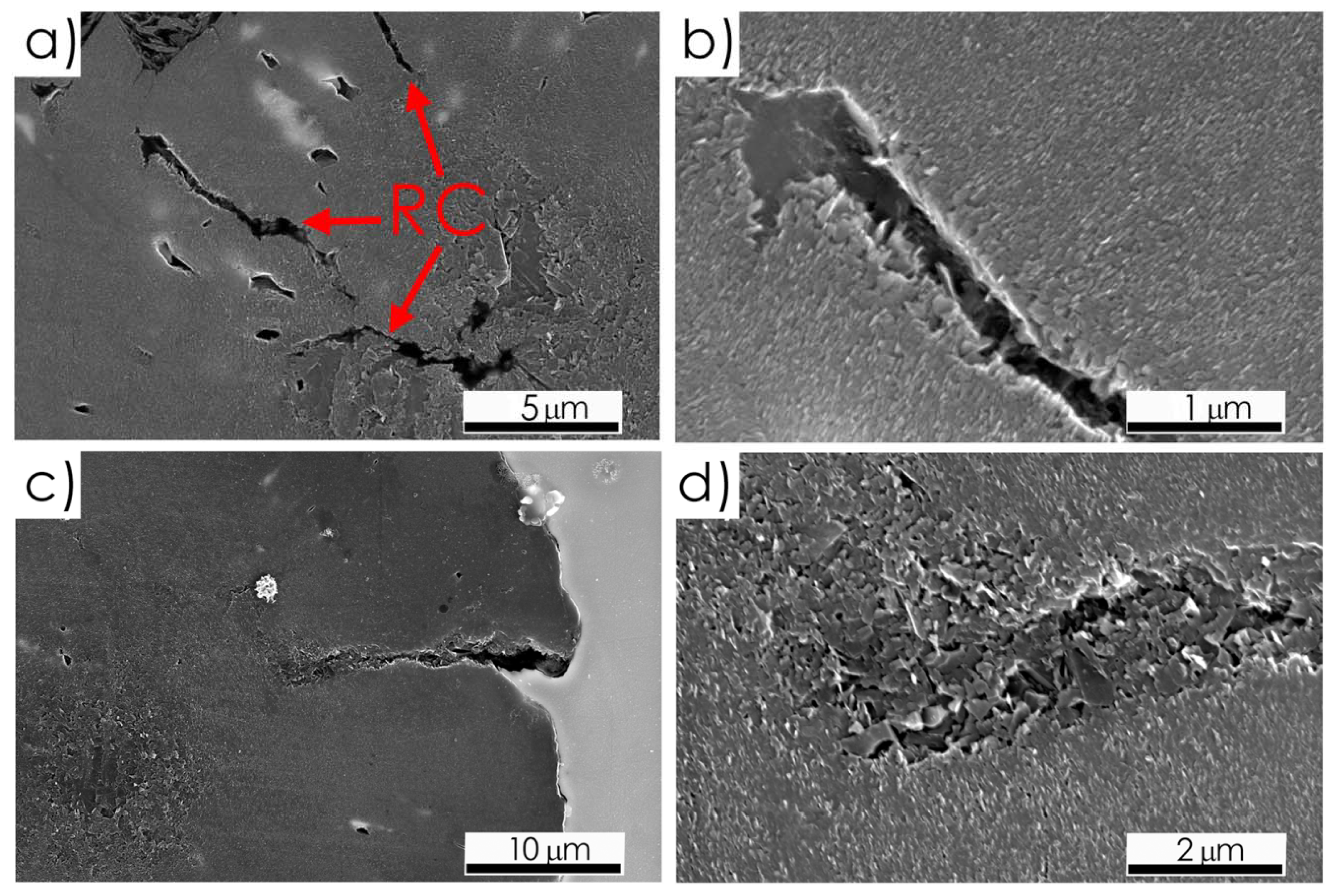
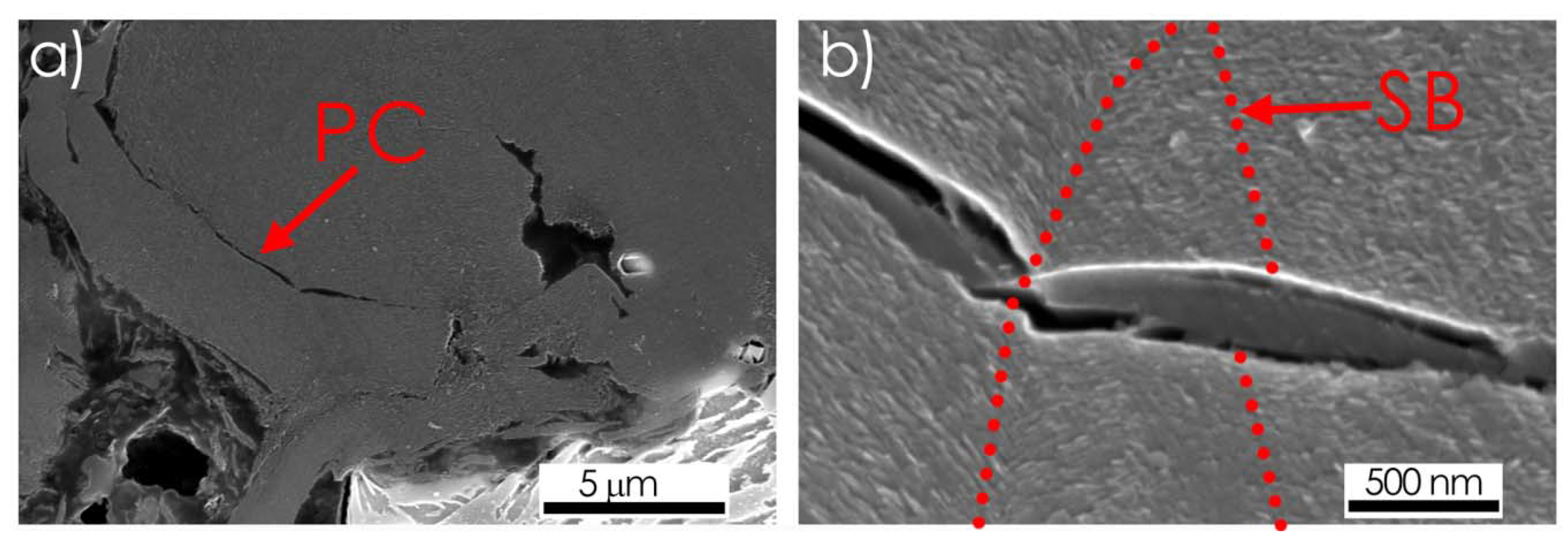
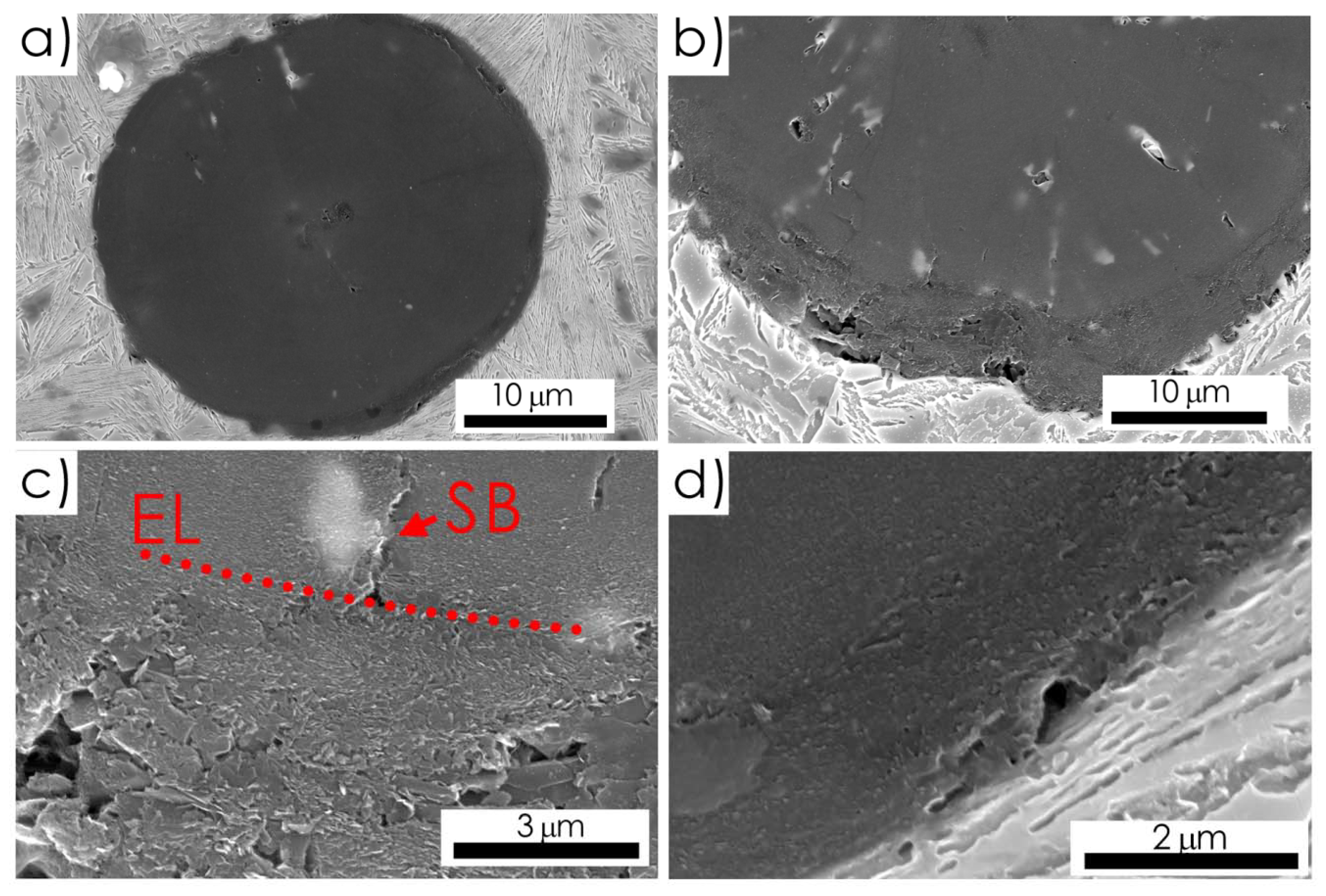
3.1. Internal Destruction Inside Graphite Nodule

Detailed microscopic observations revealed that some effects of the internal destruction, in the form of the characteristic micro-voids, were visible in the center of the spheroid’s cross-section, even in those spheroids located more than 5 mm from the main fracture, where the deformation rate was already rather low. Thus, they can be attributed to the early stage of the material damage.
The micro-voids (Figure 3), visible around the nucleus of the examined spheroid, were characterized by a less ordered, nonsectoral arrangement of base graphite plates. In works published previously [27,28], this effect of the spheroid destruction was denoted as a central disgregation.
In the SNi9 alloy specimen, tested in as cast state, the pure G-M debonding in the pole area of the G-M interface, defined as a simple break in the graphite-matrix bonds, appeared as the next stage of damage. However, a morphology of the spheroid’s surface seemed to point out that G-M debonding was preceded by the formation of a layer of shifted graphene plates at the G-M interface (Figure 4).
A mutual displacement of individual layers of graphene was observed in two sites of the spheroid’s cross-section: In the center (Figure 3 and Figure 5a) and on the periphery (Figure 4 and Figure 5b).
In spheroids located at a distance shorter than 3 mm from the main crack, both in those partially separated and in those still completely embedded in the matrix, a complex network of internal cracks was visible (Figure 6a). Some cracks, oriented radially, initiated in the center of the spheroid (Figure 6a,b) reached the boundary of the outer rim (Figure 6b) after passing through the entire core.
In the spheroids situated near the main fracture surface, some radial cracks were initiated on the G-M interface in the equatorial region (Figure 6c) and then passed between two radial sectors, to finally stop in the area of shifted graphene plates still remaining in the core (Figure 6d).
Traces of decohesion in the form of concentric cracks were observed in the outer layers of the spheroid. Details of the path of a such peripheral crack were presented in Figure 7. The concentric cracks were formed circumferentially, probably between the primary sectoral core and the subsequent outer layers (Figure 7a). As it is documented in Figure 7b, the first traces of decohesion appeared as a result of the separation of individual graphene plates. Then, the developing crack changed direction at the boundary of adjacent radial sectors.

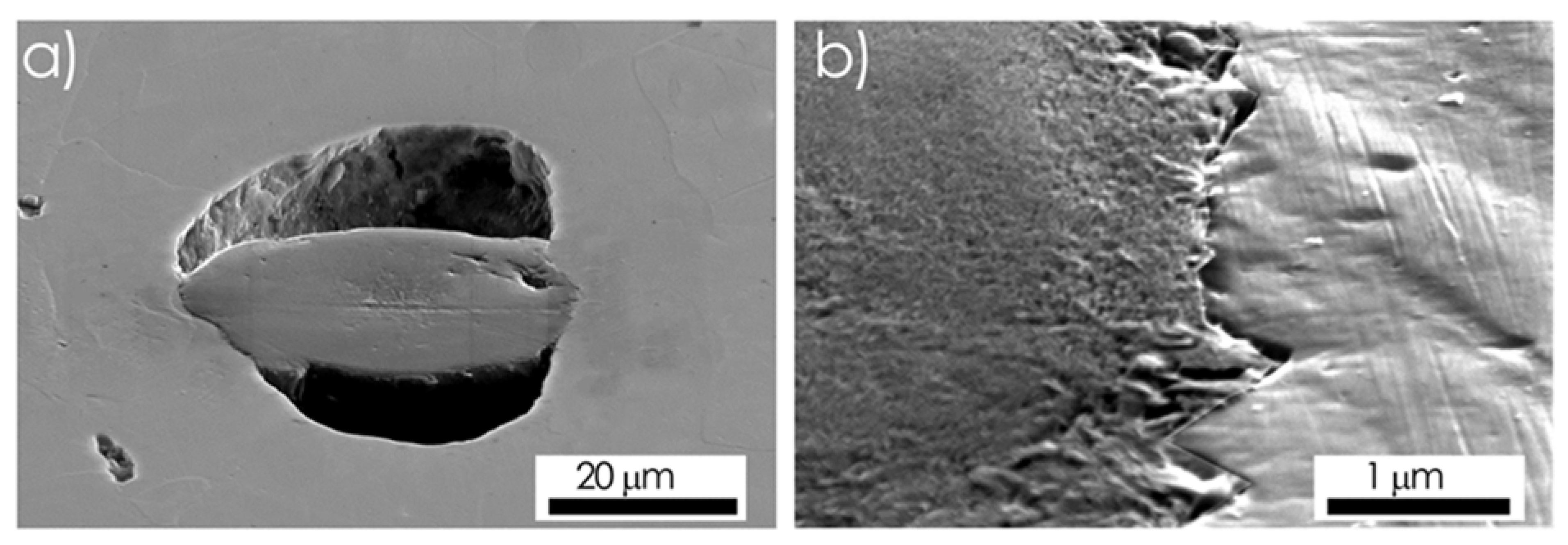
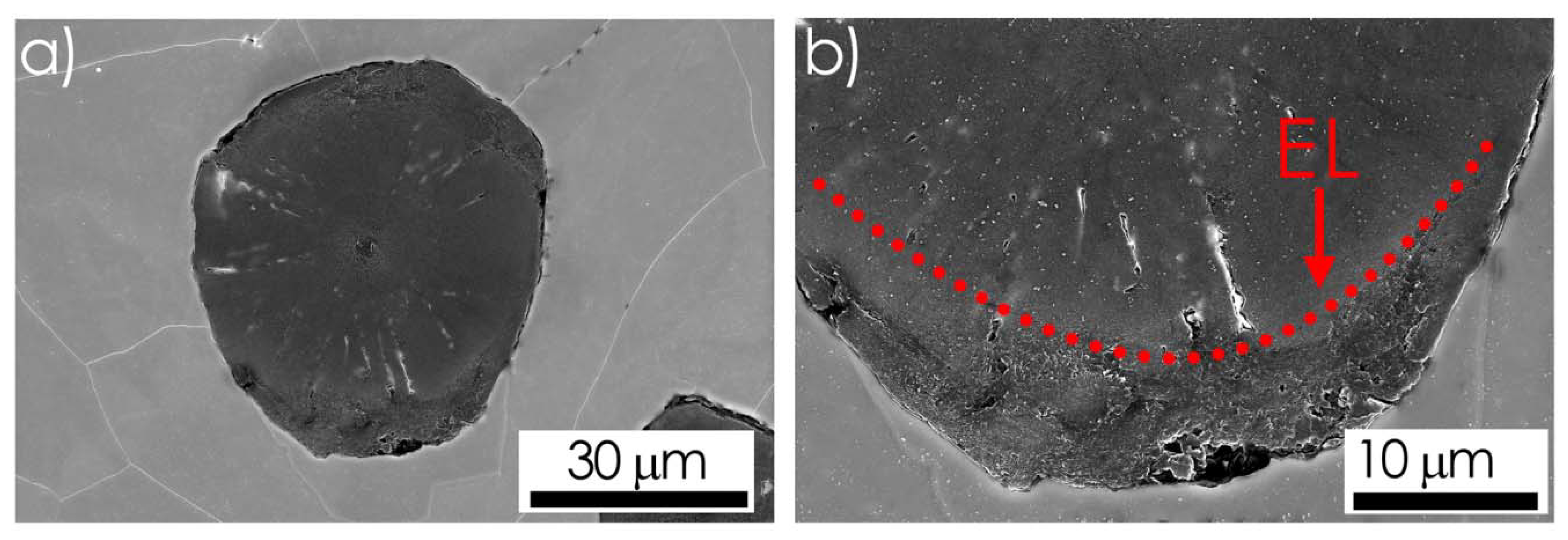
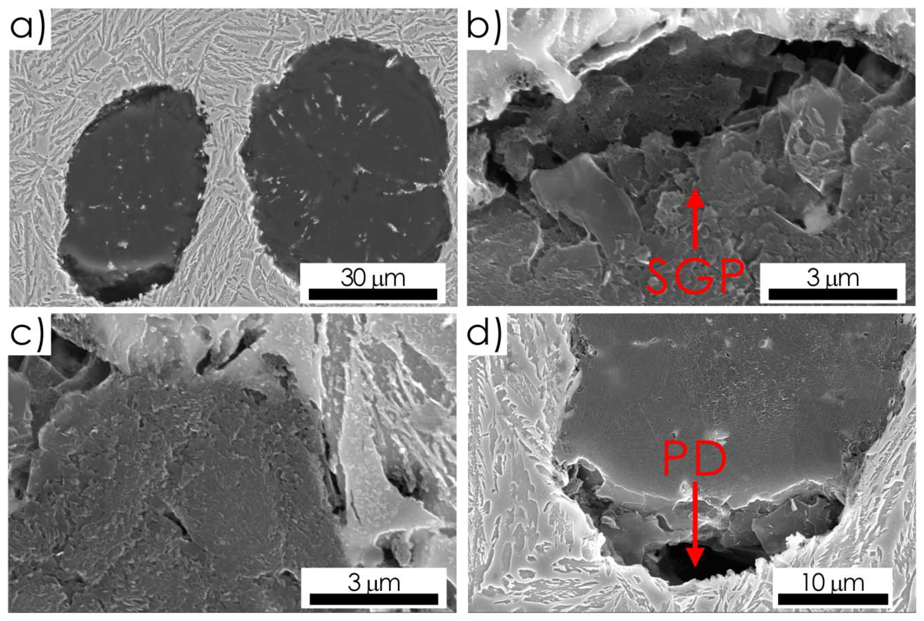
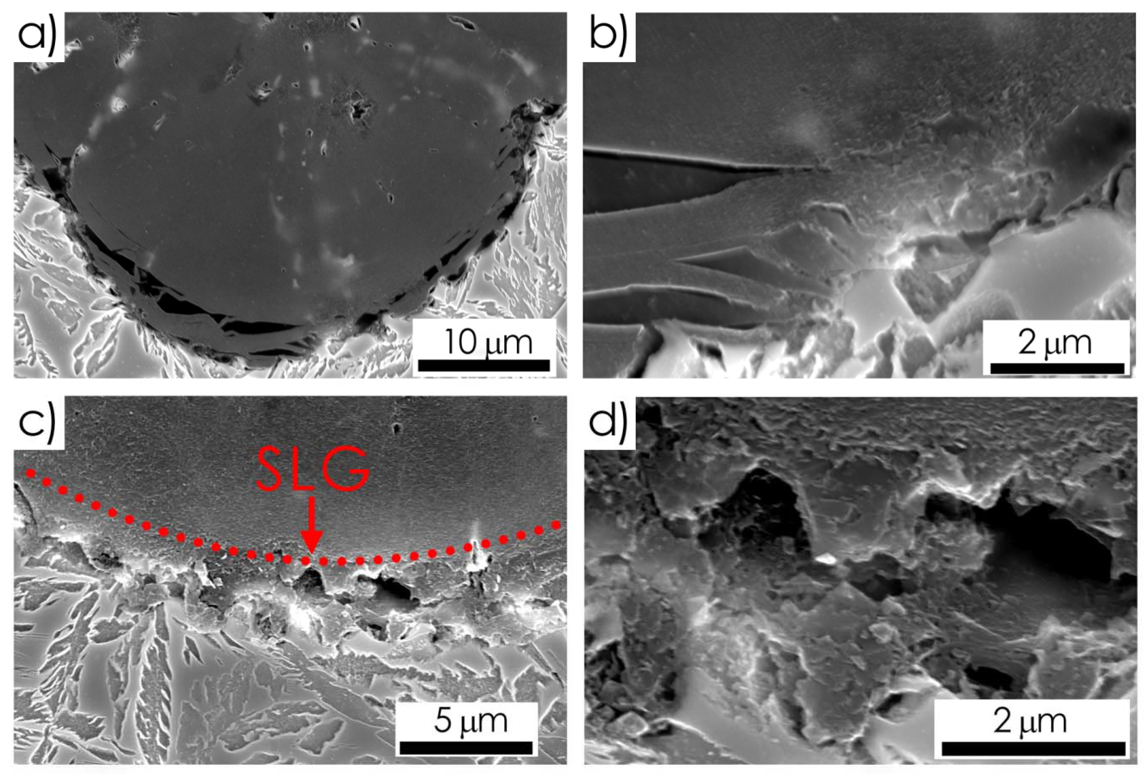
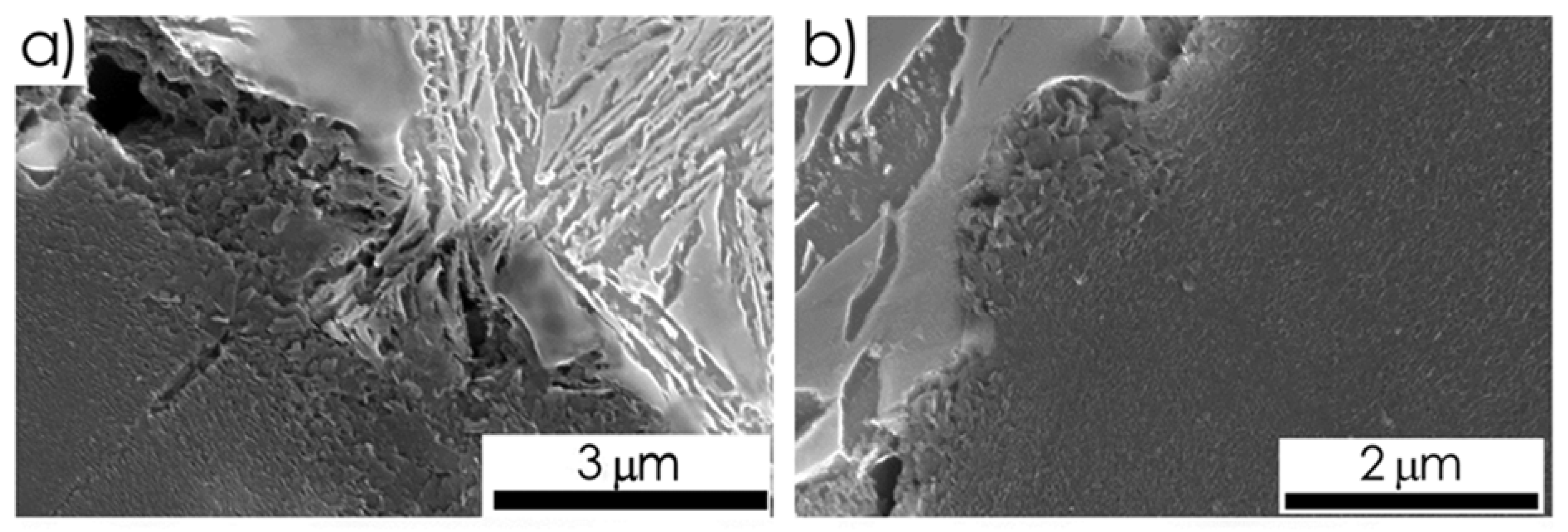
3.2. Graphite-Metal Matrix Debonding

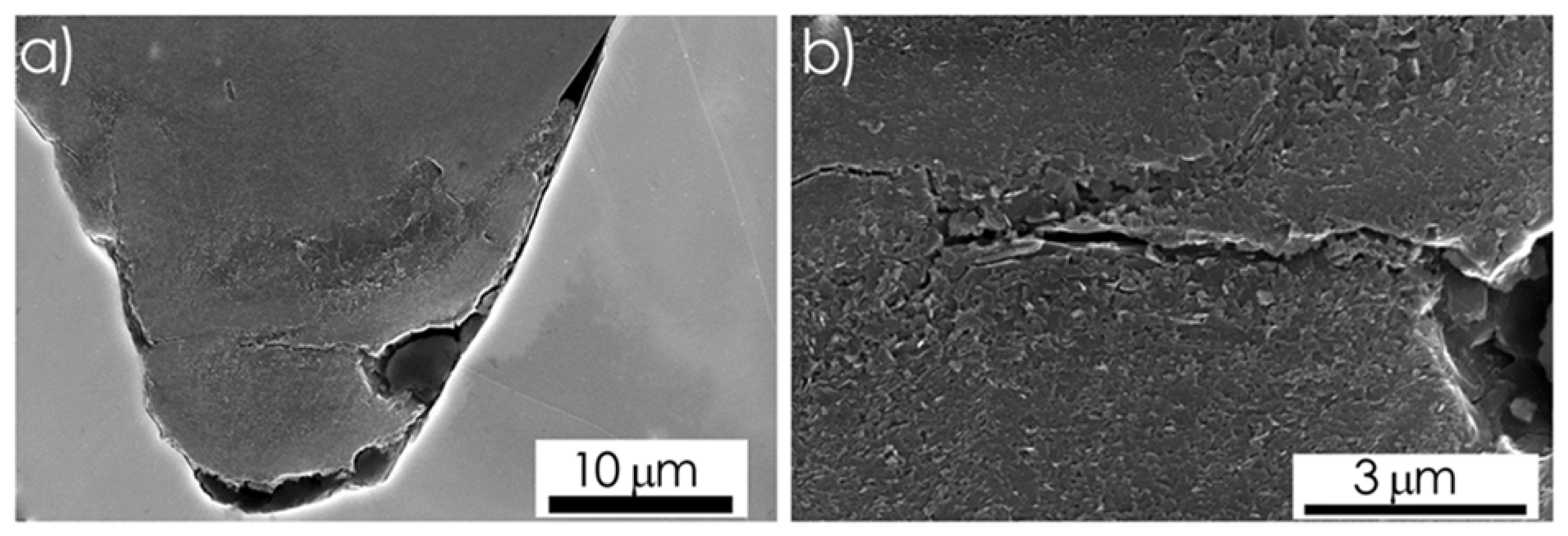
3.2.1. Debonding at Graphite/Ferrite Interface

In the spheroidal ferritic cast iron alloys examined in the as-cast state (SNi9 and SNi11 specimens) effects of the G-M debonding were observed not only near the main fracture surface but also in a distance of 1 mm and longer (Figure 8 and Figure 9). The lens-like or elliptical voids, elongated along the direction of external tensile stress, appeared in the area of the spheroid pole even before the initiation of cracks in the adjacent metal matrix (Figure 8a).
In the equatorial area, cohesion at the G-M interface was sustained longer (Figure 8 and Figure 9). Nevertheless, in the matrix corresponding to the nodule equator, a zig-zag profile of the G-M interface and the traces of local matrix deformation, as shear bands and twins (Figure 8b), were visible.
In the examined micro-areas at a distance from the main fracture of 3 mm or more, the pure pole G-M debonding effect was less frequently observed. At this distance, the first traces of destruction of the spheroid in the form of a layer of shifted graphene plates appeared in its outer shell (Figure 9b). In the most ductile specimen (the SNi9 one), such traces of destruction in pole areas of spheroid could be observed even at a distance of 5 mm from the main fracture surface.
Some visual effects of the apparent spheroid elongation along the stress direction appeared (Figure 9b) with the shift of graphene layers in the pole area. Especially, in microregions near the surface of the main fracture, the observed ratio of apparent elongation of some spheroids damaged in such a way, was quite large (Figure 10a) and comparable to that observed for the ellipsoidal voids formed after the pure pole debonding (Figure 8a).
However, in the area near the fracture surface mainly a complex path of cracks, i.e., onion-like cracks, was observed [26,29]. It seems that such cracks were initiated by separating the outer shell of the spheroid from its core in the pole area (Figure 11a). There was also a complete debonding at the G-M interface in the equatorial area, probably at the last stage of separating the spheroid from the matrix (Figure 11a). In this part of the G-M interface at the pole, where only a partial debonding took place, concentric layers of shifted graphene plates were visible (Figure 11b).
It is found that also the cracks at the G-M interface and inside the spheroid, visible in Figure 10, can be considered as an initial stage of the formation of onion-like cracks.

3.2.2. Debonding at Graphite/Ferrite Interface

The pearlite/graphite interfaces dominated in the ADIs specimen, examined as cast state. The traces of the pole G-M debonding at the pearlite/graphite interface were revealed mainly near the main fracture (Figure 12). The other traces of the G-M debonding and those of the internal destruction of nodules were practically not noticed at a distance larger than 1 mm from the main fracture surface.
Detailed observations of the G-M debonding area, especially near the spheroid pole, revealed a different effect of ferrite and cementite lamellas on the decohesion start at the G-M interface. As it is presented in Figure 12b–d, cementite lamellas were very often kept in contact with graphite, while the ferrite plates were found to be already separated from the spheroid surface. Therefore, the total G-M debonding may have been delayed.

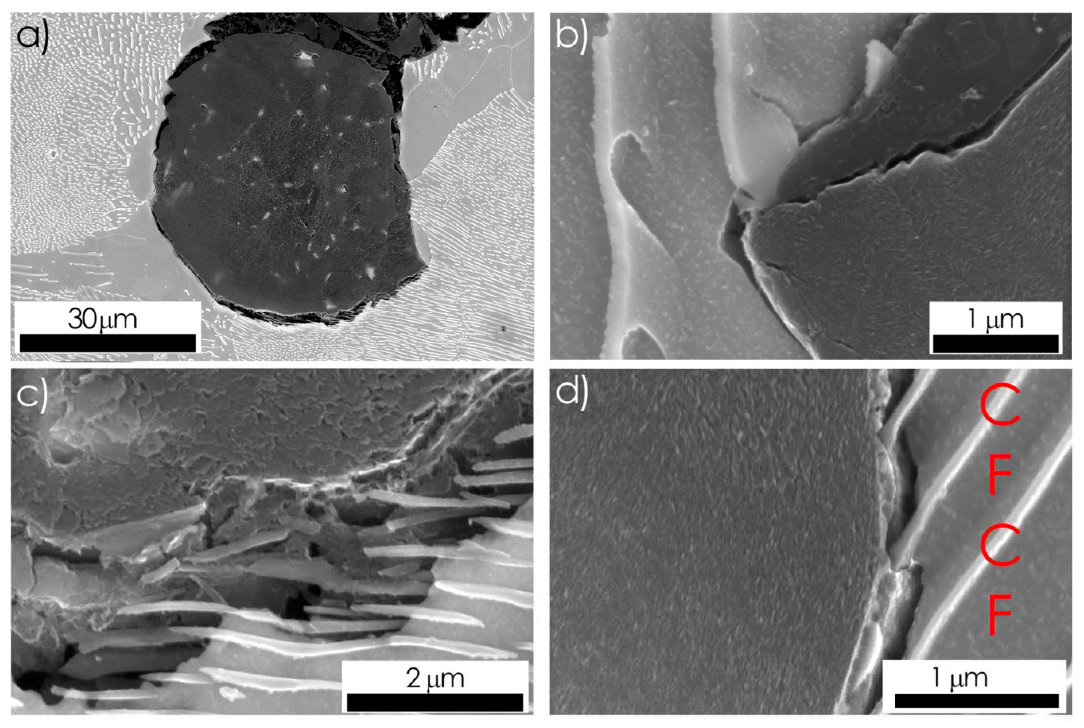
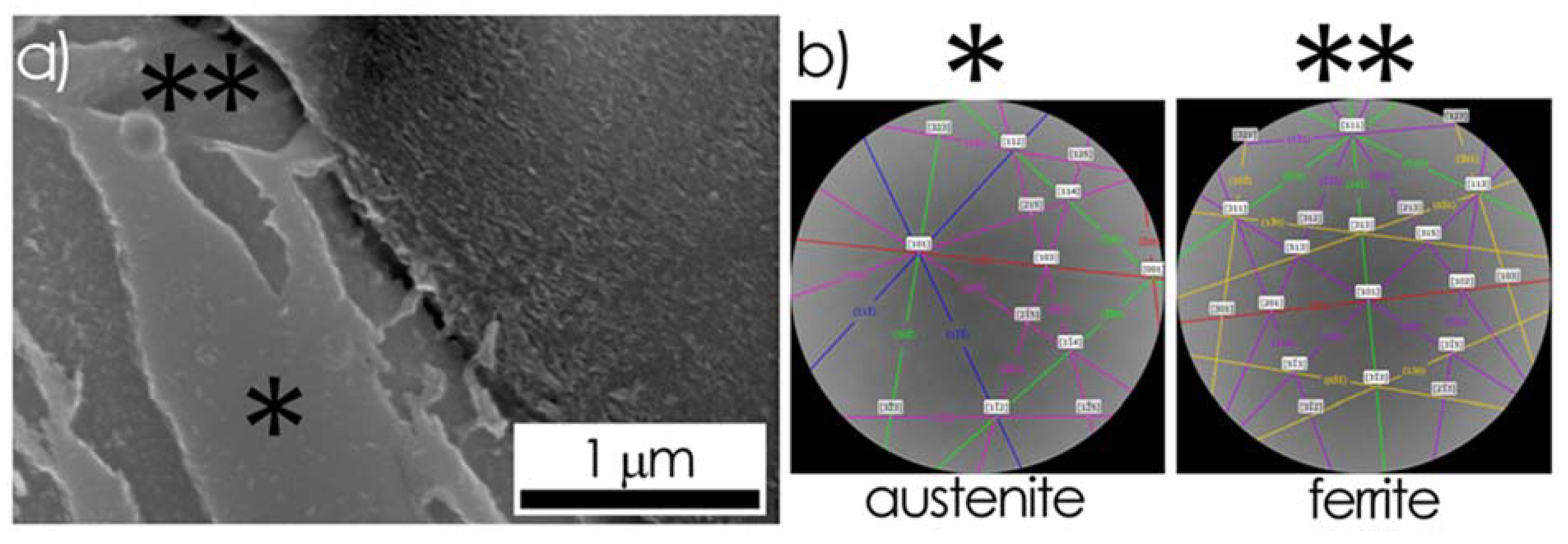
3.2.3. Debonding at Graphite/Ausferrite Interface

In alloys having the ausferritic matrix, the first traces of G-M debonding in the form of micro-voids, appeared in spheroids located at a distance larger than 3 mm from the main surface of the crack (Figure 13 and Figure 14). The G-M interface morphology features visible in Figure 13a, suggest that in some areas of the interface, a close G-M contact was remained for a longer time. Electron backscatter diffraction patterns, shown in Figure 13b, recorded in two microregions marked in Figure 13a, allow identifying areas of closer G-M contact as austenite plates (Figure 13b). Similarly, the result of the EBSD analysis presented in Figure 13b, revealed that the G-M debonding was initiated in ferrite microregions.
In samples with the ausferrite matrix (Figure 14), the layers of displaced graphene plates began to form in the outer shell of the spheroid (primarily at its poles) even before the G-M debonding was started (Figure 14b–d). Radial microcracks seemed to be initiated in the core and then they passed along the boundaries between sectors up to the center of the spheroid (Figure 14b,c).
Nevertheless, the observed G-M debonding mode was very diverse, even in spheroids located at the same distance from the fracture surface (Figure 15). While in one spheroid the total G-M debonding occurred at both poles (Figure 15a,b,d), in the other one only a layer of displaced or crushed graphene plates was observed (Figure 15c).
However, in the spheroids near the main fracture surface, a damage mode typical for the onion-like crack was mainly observed (Figure 16). It was characterized by a crack path passing circumferentially between the core and the outer shells of the spheroid. In addition, it was observed that some changes in the outer layer of the spheroid appeared after applied heat treatment were reflected in the course of the internal crack path.
As a result of the heat treatment, especially cyclic austempering, incorporation of matrix particles into the graphite spheroid took place at the G -M interface (Figure 16 and Figure 17). In a spheroid with morphology modified in this way, the first peripheral crack began to develop along the boundary between the core and the primary outer shield, while the second crack passed between graphite and embedded matrix particles.
In addition, some traces of damage can also be observed at the G-M interface, in the form of delamination (Figure 16d) and displacement of graphene plates (Figure 16b,d and Figure 17b).

4. Discussion of the Results

The framework for discussing the results was determined by two phenomena listed in the material damage sequence: (I) Destruction of the graphite spheroid and (II) graphite-matrix debonding. Microscopic observations of the examined specimens showed that discontinuities within graphite spheroids usually develop gradually as the specimen deformation increased. The presented morphological classification of these discontinuities takes into account their location on the nodule cross-section: Central discontinuities, defined as “disgregations” (Figure 3 and Figure 5a), and internal cracks having radial or diagonal (Figure 6), and peripheral/circumferential paths (Figure 7).
A small central discontinuity, visible as a cavity on the cross-section of the spheroid, was formed, as a result of breaking bonds between particular layers of graphene by a randomly oriented tensile force [27,28]. The morphology of these discontinuities was characterized by the presence of concentric, bent layers of graphene, in the nucleus area. In these areas, the growth of the graphite crystal proceeded on the faceted front, by attaching individual carbon atoms to subsequent crystallographic planes. The results of numerical simulations of residual stress distribution [20,21,27] showed their concentration in the center of the spheroid. Therefore, such central “disgregations” were recognized as initiators of radial cracks in spheroids [10,21,27,28].
However, the radial cracks were not always observed (Figure 3a) in spheroids with visible central disgregation, especially at a larger distance from the main fracture surface, in the area of less strain rate. Local compressive stresses at the G-M interface may prevent the radial crack opening, as it was previously stated [26,27,28,29].
In all tested specimens, the traces of the radial crack initiation were observed not only in central disgregations, but also at the G-M interface (Figure 6, Figure 15, Figure 16, Figure 17 and Figure 18), what was previously mentioned in the work of Cooper et al. [8]. The misorientation of graphene blocks between sectors [25,34], especially in large spheroids, could be not enough to accommodate all network mismatches that resulted from the multiplication of grown ledges [25,34]. Therefore, internal areas of open volume defects, and even small cavities on the matrix-graphite interface (Figure 9 and Figure 10), seem to be preferred initiation sites of radial cracks. The radial cracks mainly passed along the intersectoral boundaries in the core of spheroid (Figure 6, Figure 14b,d, Figure 17a and Figure 18a). The choice of such a path can be explained by possible weakening of bonds due to crystallographic mismatch between graphene plates and by an increase in the residual meridional stress located along the sector boundaries, as demonstrated in the numerical simulation in Ref. [27].
Peripheral cracks were observed in spheroids completely embedded in the matrix (Figure 7), as well as in those where the G-M debonding was previously initiated (Figure 6 and Figure 11). Observations carried out at microscopic magnification of 80000x (Figure 18b) showed that the peripheral crack starts with breaking of bonds between basic graphene plates in one sector and then passed to the neighboring one (Figure 7b). The binding energy of Van der Waals bonds (7 kJ/mol) connecting the basic graphene planes in the elementary cell along the “c” direction, is rather small as compared to the binding energy of covalent bonds (524 kJ/mol) between carbon atoms in the graphene plane along the “a” direction (Figure 1a) [11,23]. The covalent bonds in the basic plane (along the “a” direction) were less often broken also due to their more random orientation relative to the direction of tensile stress [34,35]. Thus, both types of internal cracks identified in the observed graphite spheroids usually passed through the area of weakened cohesion, the radial cracks along sector boundaries, and the peripheral cracks between individual graphene plates.
In spheroids, in which no direct traces of the G-M debonding were recognized a mutual displacement of graphene plates in their outer shell was revealed (Figure 4, Figure 5b, Figure 7b, Figure 8b, Figure 9b, Figure 14b–d, Figure 15b–d, Figure 16c,d, Figure 17 and Figure 18c).
The “a-a” graphene plates in the outer shell of spheroid (visible in Figure 18c) appear to be parallel to the direction of tensile stresses. Observations made by transmission electron microscopy (TEM) [35,36] on the spheroid cross-section showed that individual blocks of graphene in the outer shell are smaller than that in sectors located in the central core. In addition, it was found that the degree of relative misorientation between them in the outer shell is greater than in the core and similar to that in “microcrystalline graphite” [35].
Thus, it could be assumed, that local stresses at the G-M boundary that are active at an early stage of matrix deformation, could cause displacements of small blocks of graphene in the outer shell, although they are still insufficient to cause the irreversible G-M debonding and cracks in the metal matrix.
Typical microstructural effects appearing at successive stages of spheroid damage under tensile stress are schematically summarized in Figure 18 as follows: Radial cracks (Figure 18a), peripheral cracks (Figure 18b), and displacement and rotation of graphene blocks in the outer shells (Figure 18c).
Observations of the fracture surface showed that after the complete specimen failure, spheroids visible on the fracture surface were completely or only partially separated from the matrix [30]. However, in our work the traces of an initial stage of separation from the metal matrix, were revealed on both poles of the spheroid even at a distance larger than 5 mm from the main fracture.
In contrast, a cohesion on the G-M interface in the equatorial area was usually maintained longer, regardless of the matrix microstructure (Figure 8, Figure 9, Figure 12 and Figure 14). Analysis of the stress field along the spheroid’s equator in Ref. [27] during tensile tests assumed a domination of tangential stresses. Slip lines and shear bands observed at the nodule equator in the ferritic matrix (Figure 8b) could confirm its local deformation due to a tangential stress activity at the G-M interface. Therefore, in the equatorial area of the G-M interface, only mutual displacement of graphite and matrix occurred in the early stage of damage.
The pure G-M debonding phenomenon was defined as a complete separation of graphite nodule from the alloy matrix along the G-M interface [18,28]. In situ observations of the G-M debonding course [26,28,29,34], showed that this process began when the actual stress exceeded the yield strength of the metal matrix. According to Bonora [18], the pure G-M debonding could begin at a very early stage of a tensile experiment, even in the elastic range of metal matrix deformation. However, the value of the local tensile stress must overcome cohesion forces at the G-M interface. The strengthening of the G-M interface can be attributed to two phenomena: The unsaturated van der Waals bonds on graphite nodule surface (as suggested by He [9]), and compressive stress field in the metal matrix around spheroid [18,20,28].
The effect of the G-M interface strengthening by local residual stress was attributed to incompatible matrix (M) and graphite (G) deformation [28] and thermal stress arising on the surface of the spheroid when cooling the alloy in solid state [20,27]. The value of these local stresses reached a maximum near the G-M interface, which was confirmed based on the results of dislocation density calculations. It was shown that the dislocation density in matrix at the G-M interface was 7 ~ 6.4 × 10¹² m−2, and at a distance of 20 µm from the interface only 1.2–1.6 × 10¹² m−2 [37]. The estimated value of critical stress, necessary to G-M debonding at room temperature was less than 80 MPa [10], and rather small compared to the yield strength of tested cast iron samples (Table 2). In the ferritic alloy with high ductility (SNi9), the pure G-M debonding without visible spheroid destruction was observed mainly in the regions near the main crack (Figure 8a). Based on the size of the voids around graphite spheroid in the pole areas, it can be assumed that in these regions of the specimen a high deformation of matrix occurred. Thus, this result can confirm previous findings of Bonora [18] and di Cocco [28].
Although the pure G-M debonding was the main damage mechanism in the pearlitic cast iron, as reported in [30], our observations of the G-M debonding in the pole area of the perlite/graphite interface showed that the cementite lamellas remained still in close contact with the surface of the spheroid (Figure 12), while the ferrite plates were already separated.
Thus, this local decohesion delay in the areas of contact of graphite with cementite lamellas can be considered as an effect of the microstructural strengthening of the G-M interface. A similar tendency to delayed separation was found for austenite plates on the G-M interface in ausferritic cast iron (Figure 13 and Figure 15).
At this stage of the examinations, it is difficult to indicate physical causes of a such local cohesion enhancement. However, factors such as chemical composition, interface energy, and crystal structure of phase constituents should be taken into consideration.
Other internal damage mode of the spheroid, very often observed in the examined samples, can be described as “onion” crack [28,29,30].
Onion-like cracks were found in all alloys tested, with the exception of ADI in the cast state, in which the graphite/pearlite interfaces dominated. According to our observations, the onion-like debonding developed as last stage of the peripheral cracks. The main path of these cracks passed along the boundary between the sectoral core of the spheroid and its outer shell (Figure 6, Figure 14 and Figure 17). This result is consistent with the result obtained during the in situ tests presented in Refs. [26,28,29,30]. Such a path of peripheral crack leading to the final onion-like debonding could be favored by some characteristic features of the boundary between the core and the outer rim, i.e., step change in the microhardness [12,28,29] and an increase in the residual stresses value [10,28]. The isothermal austempering [4] carried out at high temperature (the ADI 390 specimen) or for a long time (the ADI cyclic specimen) caused modification of the spheroid morphology. Therefore, an additional factor determining the path of damage appeared. The results of the scratch tests carried out to assess the strength of the G-M interface showed that its value may also be affected by the morphology of the G-M interface, i.e., the shape of graphite [38]. In the superficial layers of the spheroids, embedded small metallic matrix particles were visible. New G-M interfaces between graphite and embedded matrix particles constituted additional crack paths. Thus, the onion-like cracks path in heat-treated alloys has become more complicated as compared to that observed in the as cast state (Figure 16).
Another specific feature of the damage process occurring in the tested samples was the apparent “elongation” observed in spheroids located at a short distance from the main surface of the crack (Figure 10 and Figure 15). Such an apparent "elongation" of the spheroid, called “healing” or “graphite flow”, was observed during a high temperature tensile test [26], and also under compressive load at room temperature [14].
The effect of visual elongation of graphite nodules revealed in the examined specimens resulted from gradual filling of micro-voids, forming at the nodule poles, with crushed graphite particles from the outer shell (Figure 9, Figure 10a, Figure 14 and Figure 15). According to our observations, only the outer layer of the graphite nodule seemed to "flow", while its sectoral core remained undeformed (Figure 5b, Figure 9b, Figure 10a, Figure 11b, Figure 14b,c, Figure 15, Figure 16 and Figure 17).
The damage course at G-M interface in the examined alloys determined by distance from main fracture surface and by matrix microstructure was summarized in Table 3.

5. Summary Conclusions

The analysis of the obtained results focused on the phenomenological approach to the microstructural effects of damage, mainly due to a posteriori method which was used to observe them. Nevertheless, obtained results of microscopic observations regarding selected effects of destruction in the microregion around the graphite spheroid allowed us to propose the introduction of some microstructural factors into the previously described micromechanical models of ductile cast iron damage.
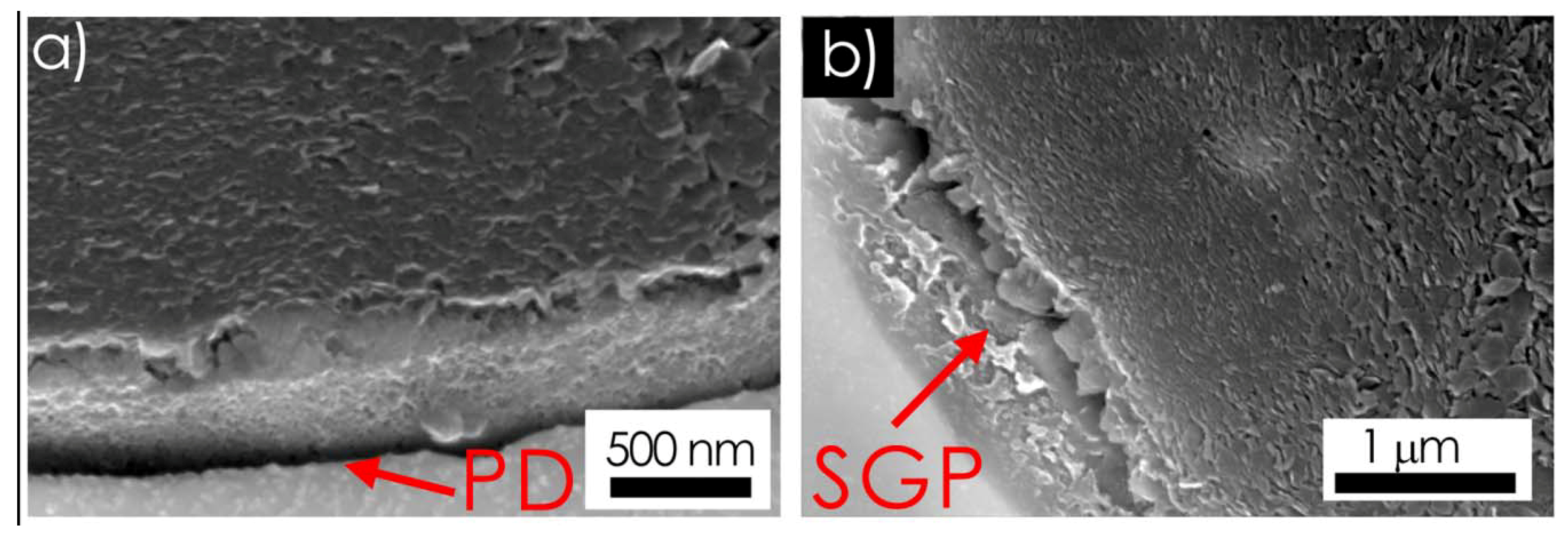
  • In alloys with a ferritic ductile matrix, on the cross-section of the specimen near the main crack, i.e., in an area with a relatively high matrix ductility, at the pole area of the graphite/ferrite interface, the dominant damage mechanism was a pure GM debonding, preceded by a slight shift of graphene plates in the surface spheroid layers.
  • The displacement of graphene plates in individual sectors of the outer shell at the spheroid poles, observed in ferrite and ausferrite matrix alloys, seems to be an intermediate stage of damage preceding the pure G-M debonding and onion-like cracks.
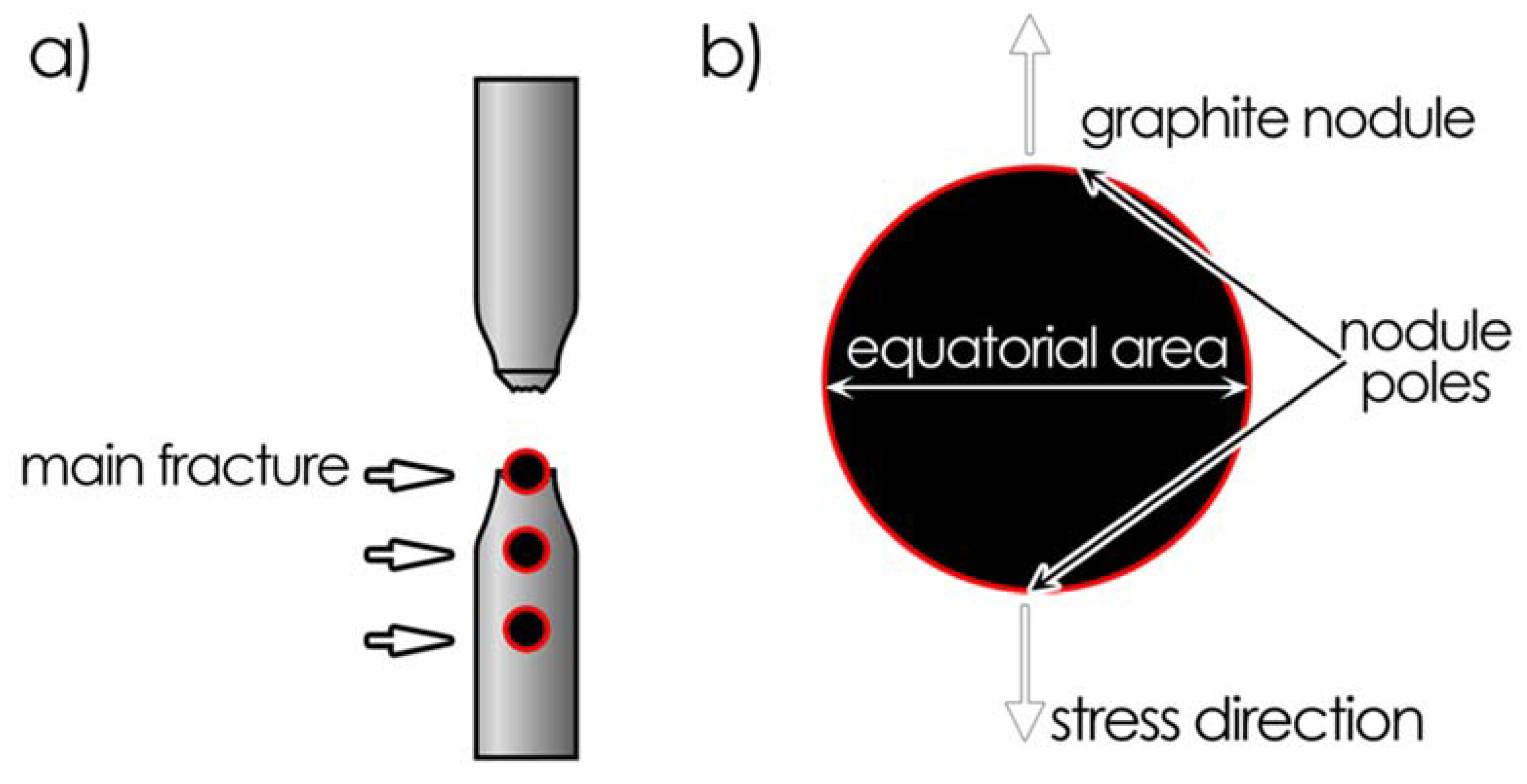
  • The effect of apparent elongation of the spheroid, observed near the main fracture surface, can be attributed to the displacement of crushed graphene plates that fill the empty spaces formed at poles of spheroid, developing as the matrix deforms. It can be assumed that such a mechanism of internal spheroid destruction results from the local interaction between the actual tensile stress, the strain rate in the matrix adjacent to the spheroid pole, the G-M boundary strength and the stress necessary to displace the graphene blocks in the microcrystalline outer layer.
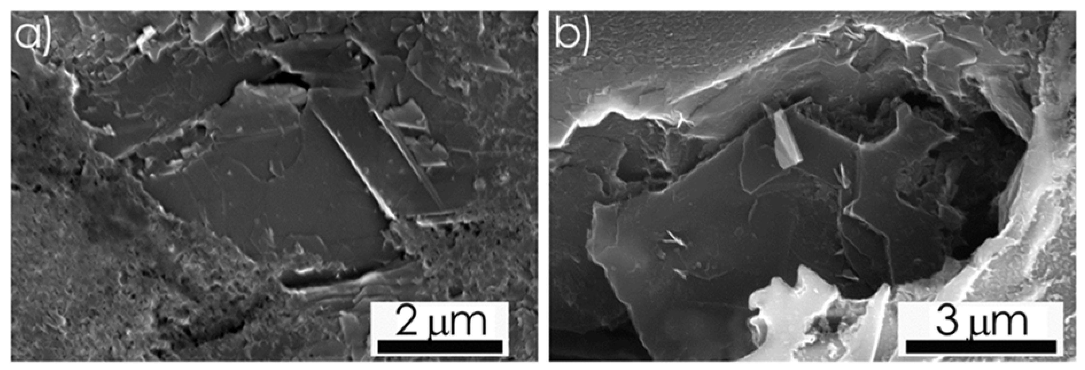
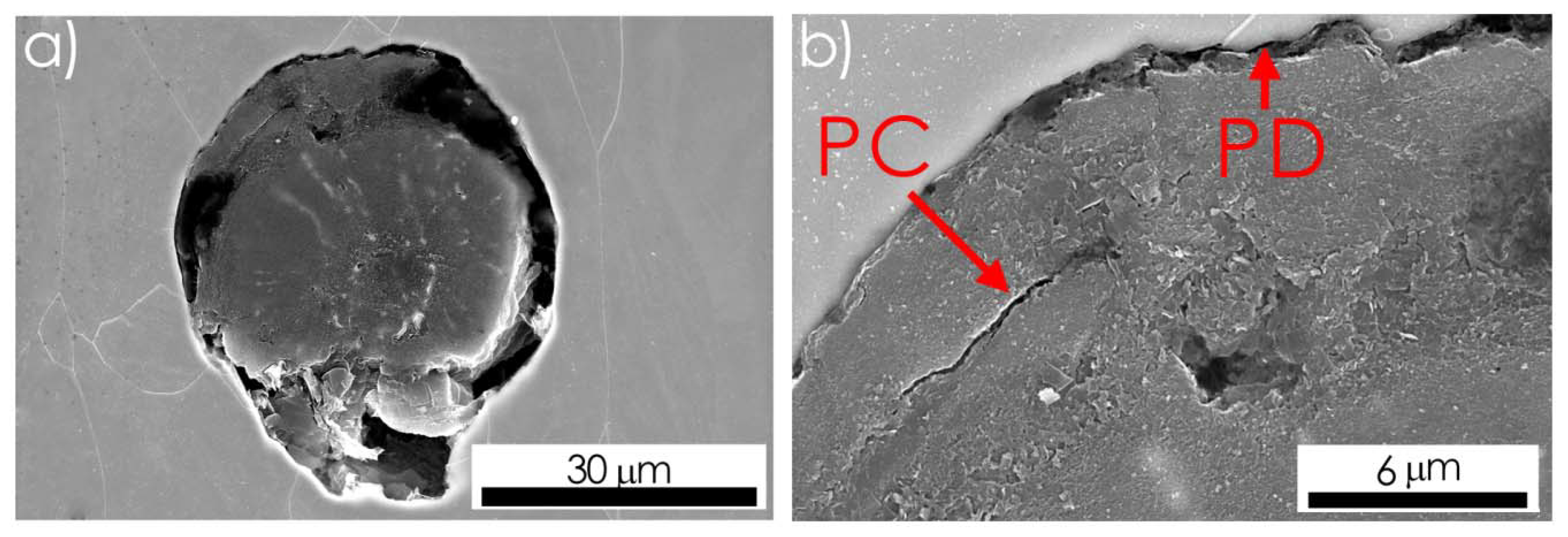
  • In multiphase alloys the G-M debonding may be blocked by some phase components of matrix, as indicated by the presence of close phase contact still observed on the graphite/austenite and graphite/cementite interfaces, even when local separation at the graphite/ferrite interface was already occurred. This local delay of irreversible process of the G-M debonding can be considered one of the microstructural factors determining the actual value of the ultimate tensile strength/elongation ratio for the ductile cast iron with a multi-phase matrix.
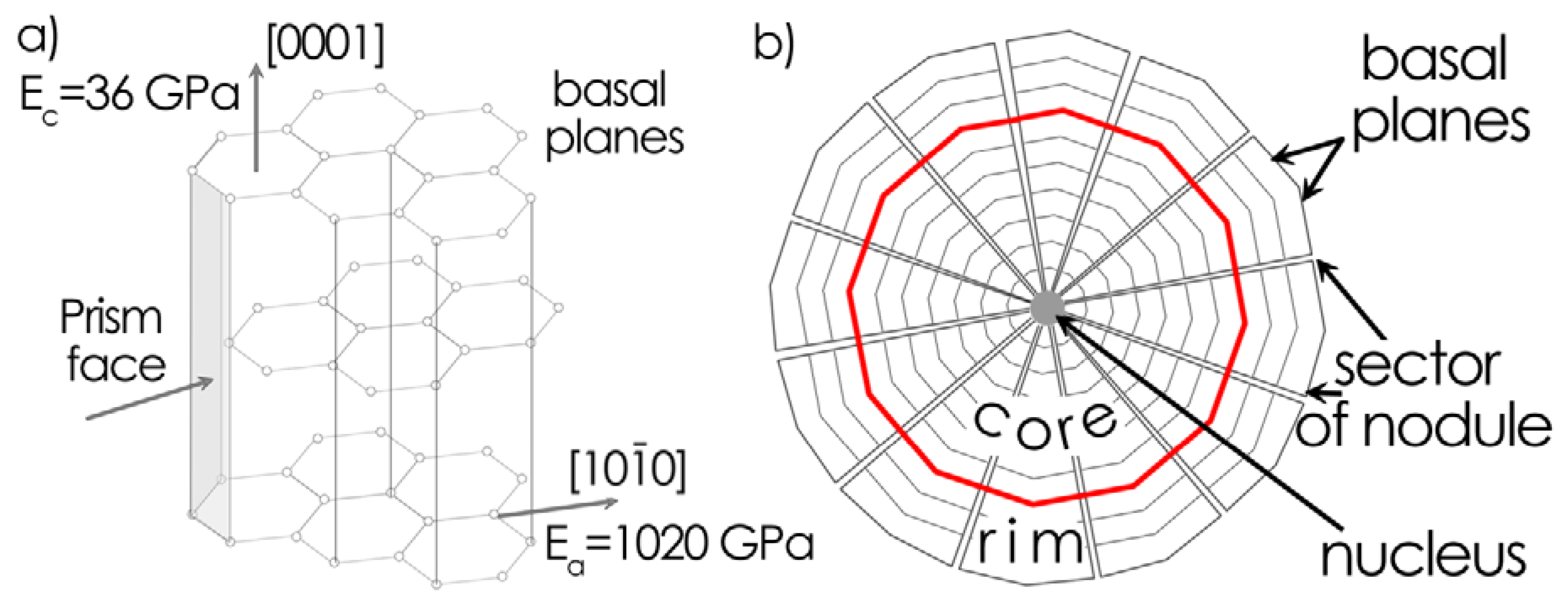
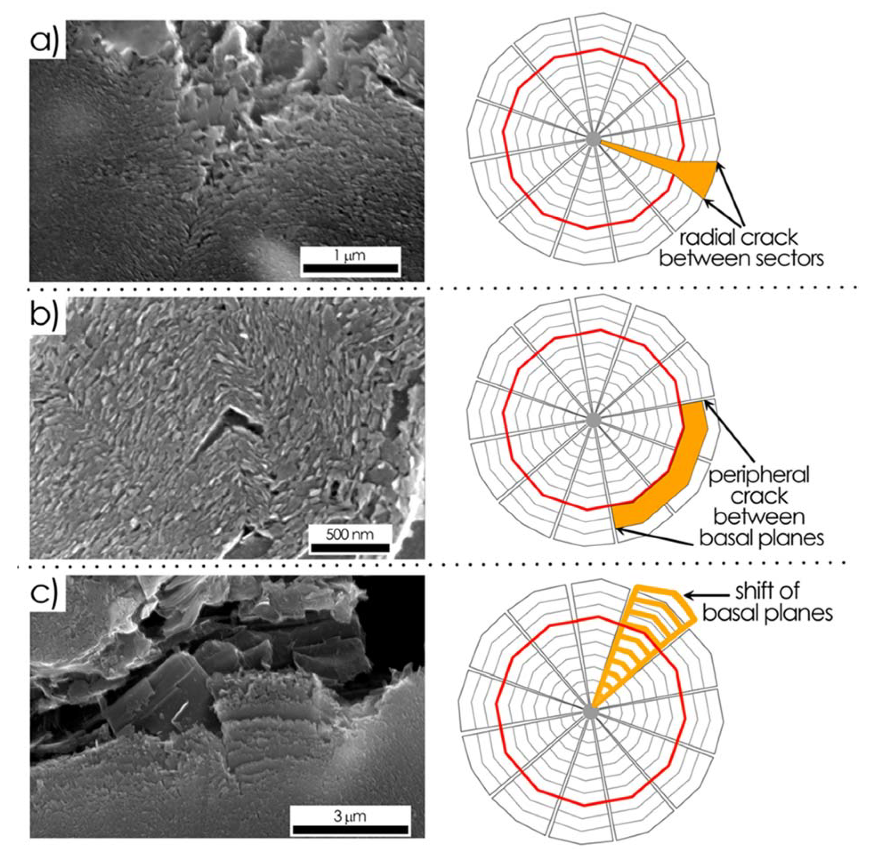
  • The results of microscopic observations suggest that internal cracks in the graphite spheroid passed through areas of weakened cohesion, radial cracks across sector boundaries, and peripheral cracks between graphene layers. Thus, the actual state of the sectoral and layered structure of the graphite spheroid and anisotropy of interatomic bonds in the graphite crystal lattice may be factors determining its destruction during a tensile test.

Author Contributions

Conceptualization, M.W. and A.P.; methodology, M.W.; software, M.W. and A.P.; investigation, M.W. and A.P.; writing—original draft preparation, M.W.; writing—review and editing, A.P.; funding acquisition, M.W. All authors have read and agreed to the published version of the manuscript.

Funding

This research was funded by the Polish National Science Centre (NCN), grant number UMO-2013/09/B/ST8/02061 and Foundry Research Institute, grant number 7003/2017.

Acknowledgments

The authors would like thank Wojciech Polkowski (Łukasiewicz Research Network—Foundry Research Institute) for his help with editing the manuscript.

Conflicts of Interest

The authors declare no conflict of interest.

References

  1. Hughes, C.H. Ductile Iron; ASM Handbook; ASM Casting ASM International: Materials Park, OH, USA, 2004; p. V15. [Google Scholar]
  2. Petrus, Ł.; Bulanowski, A.; Kołakowski, J.; Brzeżański, M.; Urbanowicz, M.; Sobieraj, J.; Matuszkiewicz, G.; Szwalbe, L.; Janerka, K. The influence of selected melting parameters on the physical and chemical properties of cast iron. Arch. Foundry Eng. 2020, 20, 105–110. [Google Scholar]
  3. Nofal, A.A. Advances in metallurgy and applications of ADI. J. Metall. Eng. 2013, 2, 1–18. [Google Scholar]
  4. Gazda, A.; Warmuzek, M.; Bitka, A. Optimization of mechanical properties of complex, two-stage heat treatment of Cu–Ni (Mn, Mo) austempered ductile iron. J. Therm. Anal. Calorim. 2018, 132, 813–822. [Google Scholar] [CrossRef] [Green Version]
  5. Putatunda, S.K. Development of austempered ductile cast iron (ADI) with simultaneous high yield strength and fracture toughness by a novel two-step austempering process. Mater. Sci. Eng. A 2001, 315, 70–80. [Google Scholar] [CrossRef]
  6. Fatahalla, N.; Hussein, O. Microstructure, mechanical properties, toughness, wear characteristics and fracture phenomena of austenitised and austempered low-alloyed ductile iron. Open Access Libr. J. 2015, 2, 1–16. [Google Scholar] [CrossRef]
  7. Marques, E.S.V.; Silva, F.J.G.; Paiva, O.C.; Pereira, A.B. Improving the mechanical strength of ductile cast iron welded joints using different heat treatments. Materials 2019, 226, 2263. [Google Scholar] [CrossRef] [PubMed] [Green Version]
  8. Cooper, C.A.; Elliott, R.; Young, R.J. Investigation of elastic property relationships for flake and spheroidal cast irons using Raman spectroscopy. Acta Mater. 2002, 50, 4037–4046. [Google Scholar] [CrossRef]
  9. He, Z.R.; Lin, G.X.; Ji, S. Deformation and fracture of cast iron with an optimized microstructure. Mater. Charact. 1997, 38, 251–258. [Google Scholar] [CrossRef]
  10. Dong, M.J.; Prioul, C.; François, D. Damage effect on the fracture toughness of nodular cast iron: Part I. Damage characterization and plastic flow modeling. Metall. Mater. Trans. A 1997, 28, 2245–2254. [Google Scholar] [CrossRef]
  11. Dai, P.Q.; He, Z.R.; Zheng, C.M.; Mao, Z.Y. In-situ SEM observation on the fracture of austempered ductile iron. Mater. Sci. Eng. A 2001, 319–321, 531–534. [Google Scholar] [CrossRef]
  12. Di Cocco, V.; Iacoviello, D.; Iacoviello, F.; Rossi, A. Graphite nodules influence on DCIs mechnical properties: Experimental and numerical investigation. Procedia Eng. 2015, 109, 135–143. [Google Scholar] [CrossRef] [Green Version]
  13. Fragassa, C.; Radovic, N.; Pavlovic, A.; Minak, G. Comparison of mechanical properties in compacted and spheroidal graphite irons. Tribol. Ind. 2016, 38, 49–59. [Google Scholar] [CrossRef] [Green Version]
  14. Pachla, W.; Mazur, A.; Skiba, J.; Kulczyk, M.; Przybysz, S. Effect of hydrostatic extrusion with back pressure on mechanical properties of grey and nodular cast irons. Arch. Metall. Mater. 2011, 56, 945–953. [Google Scholar] [CrossRef] [Green Version]
  15. Mohammed, A.D.; Kachi, M. Effects of Features of Graphite Nodules on Stress Concentration in Nodular Graphite Cast Iron Material under Multi-Axial Loading. Int. J. Appl. Eng. Res. 2017, 12, 656–663. [Google Scholar]
  16. Gaudig, W.; Mellert, R.; Weber, U.; Schmauder, S. Self-consistent one-particle 3D unit cell model for simulation of the effect of graphite aspect ratio on Young’s modulus of cast-iron. Comput. Mater. Sci. 2003, 28, 654–662. [Google Scholar] [CrossRef]
  17. Seetharamu, S.; Srinivasan, N.; Mangalgir, P.D. Effect of graphite size and spacing in spheroidal cast iron: An analytical on the elastic constants of analytical approach. J. Indian Inst. Sci. 1981, 63, 213–226. [Google Scholar]
  18. Bonora, N.; Ruggiero, A. Micromechanical modeling of ductile cast iron incorporating damage. Part I: Ferritic ductile cast iron. Int. J. Solids Struct. 2005, 42, 1401–1424. [Google Scholar] [CrossRef]
  19. Fukumasu, N.K.; Pelegrino, P.L.; Cueva, G.; Souza, R.M.; Sinatora, A. Numerical analysis of the stresses developed during the sliding of a cylinder over compact graphite iron. Wear 2005, 259, 1400–1407. [Google Scholar] [CrossRef]
  20. Andriollo, T.; Thorborg, J.; Tiedje, N.S.; Hattel, J. Modeling of damage in ductile cast iron – The effect of including plasticity in the graphite nodules. IOP Conf. Ser. Mater. Sci. Eng. 2015, 84. [Google Scholar] [CrossRef] [Green Version]
  21. Andriollo, T.; Hattel, J. On the isotropic constants of graphite nodules in ductile cast iron: Analitycal and micromechanical investigations. Mech. Mater. 2016, 96, 138–150. [Google Scholar] [CrossRef] [Green Version]
  22. Tsai, J.-L.; Tu, J.-F. Characterizing mechanical properties of graphite using molecular dynamics simulation. Mater. Des. 2010, 31, 194–199. [Google Scholar] [CrossRef]
  23. Pina, J.C.; Kouznetsova, V.G.; Geers, M.G.D. Thermo-mechanical analyses of heterogeneous materials with a strongly anisotropic phase: The case of cast iron. Int. J. Solids Struct. 2015, 63, 153–166. [Google Scholar] [CrossRef]
  24. Stefanescu, D.M.; Alonso, G.; Larranaga, P.; De la Fuente, E.; Suarez, R. On the crystallization of graphite from liquid irone-carbone-silicon melts. Acta Mater. 2016, 107, 102–126. [Google Scholar] [CrossRef]
  25. Qing, J.; Richards, V.L.; Van Aken, D.C. Growth stages and hexagonalrhombohedral structural arrangementsin spheroidal graphite observed in ductile iron. Carbon 2017, 116, 456–469. [Google Scholar] [CrossRef] [Green Version]
  26. Hervas, I.; Thuault, A.; Hug, E. Damage analysis of a ferritic simo ductile cast iron submitted to tension and compression loadings in temperature. Metals 2015, 5, 2351–2369. [Google Scholar] [CrossRef] [Green Version]
  27. Andriollo, T.; Thorborg, J.; Tiedje, N.; Hattel, J. A micro-mechanical analysis of thermo-elastic properties and local residual stresses in ductile iron based on a new anisotropic model for the graphite nodules. Modelling Simul. Mater. Sci. Eng. 2016, 24. [Google Scholar] [CrossRef] [Green Version]
  28. Di Cocco, V.; Iacoviello, F.; Cavallini, M. Damaging micromechanisms characterization of a ferritic ductile cast iron. Eng. Fract. Mech. 2010, 77, 2016–2023. [Google Scholar] [CrossRef]
  29. Di Cocco, V.; Iacoviello, F.; Rossi, A.; Iacoviello, D. Macro- and microscopical approach to the damaging micromechanisms analysis in a ferritic ductile cast iron. Theor. Appl. Fract. Mech. 2013, 69, 26–33. [Google Scholar] [CrossRef]
  30. Iacoviello, F.; Di Cocco, V.; Rossi, A. Pearlitic ductile cast iron: Damaging micromechanisms at crack tip. Frat. Integrita Strut. 2013, 25, 102–108. [Google Scholar] [CrossRef] [Green Version]
  31. Warmuzek, M.; Polkowska, A.; Gazda, A. Microscopic approach to micromechanism of damage in spheroidal cast iron. Article in press. Microsc. Res. Tech. 2020, 1–9. [Google Scholar] [CrossRef]
  32. Gouveia, R.M.; Silva, F.J.G.; Paiva, O.C.; Andrade, M.F.; Silva, L.; Moselli, P.C.; Papis, K.J.M. Study of the heat-treatments effect on high strength ductile cast iron welded joints. Metals 2017, 7, 382. [Google Scholar] [CrossRef] [Green Version]
  33. Velichko, A.; Holzapfel, C.; Mücklich, F. 3D Characterization of Graphite Morphologies in Cast Iron. Adv. Eng. 2007, 9, 39–45. [Google Scholar] [CrossRef]
  34. Lacaze, J.; Theuwissen, K.; Laffont, L.; Véron, M. Misorientations in spheroidal graphite: Some new insights about spheroidal graphite growth in cast irons. IOP Conf. Ser. Mater. Sci. Eng. 2016, 117, 1–6. [Google Scholar] [CrossRef]
  35. Theuwissen, K.; Lacaze, J.; Laffont, L. Structure of graphite precipitates in cast iron. Carbon 2016, 96, 1120–1128. [Google Scholar] [CrossRef] [Green Version]
  36. Monchoux, J.P.; Verdu, C.; Thollet, G.; Fougères, R.; Reynaud, A. Morphological changes of graphite spheroids during heat treatment of ductile cast irons. Acta Mater. 2001, 49, 4355–4362. [Google Scholar] [CrossRef]
  37. Zhang, Y.B.; Andriollo, T.; Fæster, S.; Liu, W.; Hattel, J.; Barabash, R. 3D local residual stress and orientation gradients near graphite nodules in ductile cast iron. Acta Mater. 2016, 121, 173–180. [Google Scholar] [CrossRef] [Green Version]
  38. Lopez-Covaleda, E.A.; Sepideh-Ghodrat, I.D.; Kestens, L.A.I.; Sacre, C.H.; Pardoen, T. Proposal of characterization procedure of metal–graphite interface strength in compacted graphite iron. Materials 2018, 11, 1159. [Google Scholar] [CrossRef] [Green Version]
Figure 1. A structure of graphite nodule: (a) Elementary cell of the graphite crystal lattice [23], (b) a sectorial arrangement of the crystallographic planes in the graphite nodule [25].
Jmmp 04 00022 g001
Figure 2. Arrangement of the observed microregions; (a) on the examined cross-section of specimen, (b) in graphite nodule.
Jmmp 04 00022 g002
Figure 3. Morphology of area of the initial stage of graphite spheroid destruction, the central disgregation (CD), SEM: (a) At a distance of 3 mm from fracture surface, specimen SNi11, (b) at a distance of 1 mm from the fracture surface, specimen austempered ductile iron (ADI)390.
Jmmp 04 00022 g003
Figure 4. Morphology of graphite/matrix (G-M) interface in S9Ni specimen at a distance of 5 mm from fracture surface, SEM: (a) A local pole G-M debonding (PD) at the graphite/ferrite interface, (b) a G-M debonding in equatorial area of the graphite/ferrite interface with shifted graphene plates (SGP).
Jmmp 04 00022 g004
Figure 5. Initial stage of internal destruction of graphite spheroid, SEM: (a) The central disgregation with shifted graphene plates (SGP) at a distance of 3 mm from the fracture surface, specimen SNi11, (b) a local shift of the graphene plates (SGP) at G-M interface, at a distance of 1 mm from fracture surface, specimen ADI390 (SGP).
Jmmp 04 00022 g005
Figure 6. Radial cracks (RC) inside a graphite spheroid in SNi11 specimen, SEM: (a) Radial cracks (RC) initiated in the disgregation area at a distance of 1 mm from the fracture surface, (b) enlarged area visible in (a), (c) an intersectoral crack initiated in the outer layer of graphite nodule, near the G-M interface, (d) enlarged area visible in (c).
Jmmp 04 00022 g006
Figure 7. Peripheral cracks (PC) inside graphite spheroid in ADI310 specimen at a distance of 3 mm from the fracture surface, SEM: (a) Decohesion path between core and external rim, (b) separation of the particular graphene basal plates in neighboring radial sectors, enlarged area of (a) (SB: Sector boundary).
Jmmp 04 00022 g007
Figure 8. Debonding area at the G-M interface in SNi9 specimen, around a spheroid located near fracture, SEM: (a) A pure G-M debonding at poles of spheroid, (b) a zig-zag profile at the G-M interface, traces of deformation inside the ferritic matrix.
Jmmp 04 00022 g008
Figure 9. Initial stage of spheroid destruction in SNi9 specimen at a distance of 3 mm from the main fracture surface, SEM: (a) Spheroid apparently elongated in tensile stress direction, with local debonding at G-M interface (b) outer rim morphology in bottom pole of spheroid (SB: Sector boundary; EL: External layer).
Jmmp 04 00022 g009
Figure 10. Intermediate stage of destruction in graphite spheroid in SNi9 specimen, at a distance of 1 mm from the main fracture surface, SEM: (a) Micro-cavities at G-M interface in spheroid elongated in stress direction, (b) local crack in the area of the shifted graphene plates.
Jmmp 04 00022 g010
Figure 11. Complete debonding of the graphite spheroid due to the onion-like cracking in spheroid near the fracture surface, specimen SNi9, SEM: (a) An outer rim of the graphite spheroid separated from the nodule core; (b) area of shifted basal plates locally bonded at the G-M interface (PC: Peripheral crack; PD: Pole debonding).
Jmmp 04 00022 g011
Figure 12. G-M debonding in graphite spheroid in the area near the fracture surface, ADI specimen, SEM: (a) General morphology of the G-M interface, and (bd) cementite lamellae blocking partially the G-M debonding, (b,c) in pole area, (d) in equatorial area (C: Cementite; F: Ferrite).
Jmmp 04 00022 g012
Figure 13. Local debonding path at the G-M interface in the ADI390 specimen, at a distance of 3 mm from the fracture: (a) SEM image, (b) electron backscatter diffraction patterns acquired from microregions marked in (a).
Jmmp 04 00022 g013
Figure 14. Graphite spheroid at a distance of 3 mm from the fracture surface in the ADI310 specimen, SEM: (a) The G-M interface morphology, (b,c) shifted basal graphite plates in the external rim (SB: Sector boundary; EL: External layer), (d) an initial stage of the local G-M debonding in pole area at the G-M interface.
Jmmp 04 00022 g014
Figure 15. Graphite nodules in a microregion near fracture area in the ADI390 specimen, SEM: (a) Effects of the local G-M debonding (b) the local debonding on top pole of a graphite spheroid visible shifted graphene plates (SGP), (c) matrix particles embedded in the external rim, (d) local complete pole G-M debonding (PD) on bottom pole of spheroid, visible shifted graphene plates (SGP).
Jmmp 04 00022 g015
Figure 16. Morphology of the G-M interface in a spheroid near the fracture surface, (ADI cyclic specimen), SEM: (a) Secondary layer around the primary spheroid, separated with peripheral crack in pole area, (b) enlarged area of (a), (c) a peripheral crack between primary core and secondary layer of graphite (SLG), (d) shift of basal plates in secondary layer, enlarged area of (c).
Jmmp 04 00022 g016
Figure 17. Morphology of the G-M interface, top pole area in spheroid near fracture surface (ADI cyclic specimen), SEM: (a) A micro-volume of matrix embedded in the spheroid surface rim, (b) initial stages of the G-M debonding, local cracks and shift of graphene plates.
Jmmp 04 00022 g017
Figure 18. Internal damage effects in the graphite nodule due to tensile stresses: (a) Radial crack formation between particular sectors, (b) a peripheral crack initiated between basal planes in two neighboring sectors, (c) a displacement of the basal graphite plates combined with shift and rotation of basal graphite plates in particular sectors in the external rim.
Jmmp 04 00022 g018
Table 1. Chemical composition of the examined specimens (wt%, Fe bal.).
MaterialSerie des.CSiMgMnCuMoNiCr
SCISNi93.384.020.0560.190.05-0.92 -
SNi113.253.990.0720.190.06-1.80-
ADIADI3.662.380.0700.210.530.160.850.05
Table 2. The mechanical properties and microstructure description of the examined alloys.
MaterialSpecimen DesignationMatrix MicrostructureTensile Yield Strength, MPaUltimate Tensile Strength, MPaElongation to Fracture, %
SCISNi9 (as cast)Ferrite + 10% perlite51063117.8
SNi11(as cast)Ferrite + 20% perlite55069412.0
ADIADI (as cast)Ferrite + 90% perlite5247722.7
ADI310 (austempered at 310 °C)Ausferrite (austenite)132414243.5
ADI390 (austempered at 390 °C)Ausferrite (austenite)71010258.4
Table 3. G-M debonding mode and internal cracks path observed in the examined cast iron types.
Distance from Fracture>3 mm>1 mmNear Fracture
MatrixDamage Mode
MonophaseFerriticPure G-M debondingLens -like pole voids
at G/M interface
Total debonding:
-Pure
at G-M interface
-onion-like
at core-external rim interface
Graphene layers shift
at G/M interface
Lens-like pole voids filled with crushed graphene layers at G-M interface
Peripheral cracks at core-external rim interface
Radial cracksRadial cracks
PolyphasePearliticLocal G-M debonding
F-G crack
C-G contact
Elliptical pole voids at G-M interfaceTotal debonding:
At G-M interface
Radial cracksRadial cracks
AusferriticLocal G-M debonding
F-G crack
A-G contact
Lens -like areas partially filled with crushed graphene layers at G-M interfaceTotal debonding:
-Onion like:
-peripheral cracks at core-external rim interface
Peripheral cracks at core-external rim boundaries and inside external layer of secondary particles
Total debonding:
-Onion like:
-Peripheral cracks inside external layer of secondary graphite
Radial cracksRadial cracks

