Abstract
Hot stamping by partition heating of Al–Si coated boron steel sheets is currently utilized to produce parts of the car body-in-white with tailored microstructural and mechanical characteristics. This paper investigates the evolution of the Al–Si coating and its tribological and wear performances in the case of direct heating at the process temperatures of 700 °C, 800 °C, and 900 °C, skipping the preliminary austenitization as it may happen in the case of tailored tempered parts production. A specifically designed pin-on-disk configuration was used to reproduce at a laboratory scale the process thermo-mechanical cycle. The results show the morphological and chemical variation of the Al–Si coating with heating temperature, as well as that the friction coefficient, decreases with increased temperature. Furthermore, the results proved that the adhesive wear is the main mechanism at the lower temperature, while abrasive wear plays the major role at the higher temperature.
1. Introduction
Hot stamping of boron steel sheets has become the most popular technology for producing components of the car body-in-white, in order to meet the increasing demands for the reduction of the vehicle weight and the improvement of passenger safety [1]. During the conventional hot stamping process, the sheets of quenchable boron steel 22MnB5 are usually provided with an Al–Si coating in order to prevent scale formation and decarburization when furnace heated before stamping [2]. After being heated above the austenitization temperature, they are simultaneously deformed and quenched between cooled dies, finally achieving a fully martensitic microstructure suitable for structural parts of high mechanical resistance. The conventional hot stamping process presents some evident advantages compared to conventional stamping at room temperature, such as formability improvement, forming load reduction, and spring-back decrease [3]. Furthermore, it makes it possible to manufacture components with tailored microstructure [4], and thus with different mechanical properties on different zones, enhancing their functionality. This result can be achieved by controlling the thermal cycle undergone by the workpiece, and several strategies are proposed in literature [5].
Among these, hot stamping by partition heating has been proposed to manufacture components of the car body-in-white with tailored properties to further improve the vehicle crashworthiness [6]. The main difference with the conventional hot stamping lies in the heating procedure of the blank. The blank region that requires higher strength is heated above the steel Ac3 (austenite-to-ferrite hypoeutectoid transformation) temperature, whereas the region that requires higher elongation is heated below the Ac1 (austenite-to-pearlite eutectoid transformation) temperature, with a transition region forming that characterized by a temperature gradient between Ac1 and Ac3. The heated blank is then stamped and quenched between cooled dies, following the same procedure of the conventional hot stamping process; as such, a tailored component with different volume fractions of martensite in different regions can be produced. The process allows manufacturing tailored components with less energy expenditure compared to conventional hot stamping and without introducing micro-structural changes in the areas heated below Ac1. Using this kind of process, Mori et al. [7] produced a tailored hat-shaped part using bypass resistance partition heating with high selective heating capabilities, obtaining a reduced length of the transition zone between the areas with different microstructures. Mu et al. [8] optimized the partition heating parameters, then produced an M-shaped part and a cup-shaped part with tailored properties [9]; furthermore, they developed a calibrated finite element (FE) model of the hot stamping process by partition heating [10].
The different temperatures in the heated blank may have an impact on the tribological characteristics at the blank-die interface in terms of blank coating behaviour, heat transfer, friction coefficient, and tool wear. In this context, it is mandatory to investigate the influence of the blank temperature on the tool wear characteristics, in order to have a deeper knowledge of the process.
As described above, the heated blank owns different temperatures in different regions, which may affect the evolution of the Al–Si coating. Ghiotti et al. [11] investigated the influence of the heating temperature, holding time, and cooling rate on the Al–Si coating behavior of the 22MnB5 boron steel, showing that iron diffused into the Al–Si coating forms an Al-Fe-Si ternary alloy. Pelcastre et al. [12] investigated the evolution of the morphology and microstructure of the Al–Si coating at different heating conditions, finding that Fe5Al2 and FeAl2 formed at the surface of the coating. It is worth noting that the characteristics of the Al–Si coating after heating considerably influences the hot stamping process. Gui et al. [13] and Wang et al. [14] investigated the thermo–mechanical behaviour and cracking characteristics of the Al–Si coating on hot stamped boron steel parts, showing that micro-cracks and voids appeared after austenitization, and that cracking behaviour was sensitive to the tensile state of stress.
Some researches on tribology and wear tests devoted to conventional hot stamping of Al–Si coated boron steel sheets are available in literature. Pelcastre et al. [15] investigated the mechanism of galling at elevated temperatures during hot stamping of Al–Si coated boron steel sheets by analyzing the behaviour of the actual hot forming tools. Kondratiuk et al. [16] performed sheet forming tests to study the wear mechanism by analyzing the tools used to produce a rotationally symmetrical cup. These experiments making use of actual hot stamping tests can effectively describe the tool wear phenomena, but they are costly and time consuming. Some other investigations were performed making use of laboratory testing devices, such as a sliding, reciprocating, and vibrating (SRV) machine [17], a deep drawing process simulator [18], hot strip drawing devices equipped with roller hearth furnace [19], an induction heating system [20], or infrared image furnace [21]. However, these devices are not usually able to accurately reproduce the thermal and mechanical conditions the tools cyclically encounter during the actual hot stamping process. Ghiotti et al. [22,23] proposed a novel approach to wear testing during hot stamping of boron steel sheets, using a universal tribometer equipped with a pin-on-disk configuration and an electrical furnace, capable to reproduce on the pin the same heating and cooling cycles experienced by the tools during the industrial hot stamping process. They utilized this equipment to investigate the tribological behaviour and wear characteristics during conventional hot stamping of Al–Si coated boron steel sheets [24,25].
However, on the basis of the literature review, there is still a lack of information regarding the analysis of the influence that the heating temperatures characteristic of the hot stamping by partition heating have on both the chemical and morphological evolution of the Al–Si coating and the tool wear mechanisms.
In this framework, the paper focuses on the influence that the thermal and mechanical parameters that are characteristic of hot stamping by partition heating have on the wear behaviour of the tribopair made of Al–Si coated 22MnB5 steel and AISI H11 tool steel. Firstly, the influence of the heating temperature on the evolution of the Al–Si coating is investigated by means of thermal simulation experiments, scanning electron microscopy (SEM), energy-dispersive x-ray (EDX) spectroscopy, and 3D profiler analyses. In the second section, wear tests are carried out using the experimental apparatus proposed in [22], using for the first time testing temperatures relevant to hot stamping by partition heating. The influence of the heating temperature on the tribological characteristics and wear mechanisms at increasing number of cycles is evaluated and analyzed by means of SEM, EDX, 3D profiler, and weight measurement analyses.
2. Reference Process
The reference industrial process is the hot stamping of boron steel sheets by partition heating to manufacture body-in-white components with tailored properties. The main differences, if compared with hot stamping, lie in the heating procedure: one segment of the metal blank is heated up to about 900 °C and soaked for 3–5 min to realize fully austenitization, while the remaining part of the blank is heated at about 700 °C, inducing a transition region with a temperature between 700 °C and 900 °C. The partition heating can be realized by means of specially designed heating equipment, such as furnaces with separated chambers [26], furnaces with special plate clamping devices [10], bypass resistance heating systems [7], and selective heating laser-based systems [27]. After heating, the blank is automatically transferred as quickly as possible to the forming press, with a transfer time usually controlled between 5 and 10 s. Then, the cooled dies are closed and kept clamped at a dwell pressure between 5 and 15 MPa to quench the component with a cooling rate above 27 °C/s suitable to obtain a fully martensitic structure where needed. On the contrary, the blank segment heated at 700 °C retains its initial ferritic-pearlitic microstructure regardless of the cooling rate. The industrial hot stamping process by partition heating is usually performed without any lubricant and the tools are usually reground after producing 2000–3000 tailored components, the same of the conventional hot stamping process.
3. Experimental
3.1. Materials
The blank material is the Al–Si coated boron steel 22MnB5 produced by ArcelorMittal™ (Luxembourg City, Luxembourg), whereas the material of the tools is the hardened hot working tool steel AISI H11. The chemical composition, the micro-hardness at room temperature and the surface roughness (Sa) of both materials in the as-delivered conditions are reported in Table 1. Figure 1 shows the surface topography of both the blank (a) and tool (b) in the as-delivered conditions, measured by means of a 3D surface profilometer SensofarTM (Barcelona, Spain) Plu Neox.

Table 1.
Chemical composition (in wt%), hardness (room temperature), and surface roughness of the blank and tool in the as-delivered conditions.

Figure 1.
As-delivered conditions: (a) Surface topography of the blank and (b) surface topography of the tool.
3.2. Testing Equipment
Thermal simulations and wear tests at elevated temperatures have been carried out on a Universal Mechanical Tester UMT-3 tribometer by Bruker™(Billerica, MA, USA) equipped with an electrical furnace (see the whole apparatus and some details in Figure 2). The furnace allots to heat the Al–Si coated 22MnB5 black up to 1000 °C, following a predefined thermal cycle measured by means of K-type thermocouple located inside the furnace and controlled in a closed-loop configuration by a controller unit. The blank is fixed on a rotation table inside the furnace driven by an electrical motor. The pin, mounted on the pin holder, can be moved along both the vertical and horizontal directions. The pin load and torque are measured by ultra-accurate strain-gauge sensors, which are used to calculate the friction coefficient during testing according to the Coulomb’s law. In order to ensure a constant load, the normal force is measured by a dedicated load cell, and its signal is used by the machine controller to adjust the pin vertical position. During the test, the pin temperature is constantly measured by a K-type thermocouple embedded inside it.
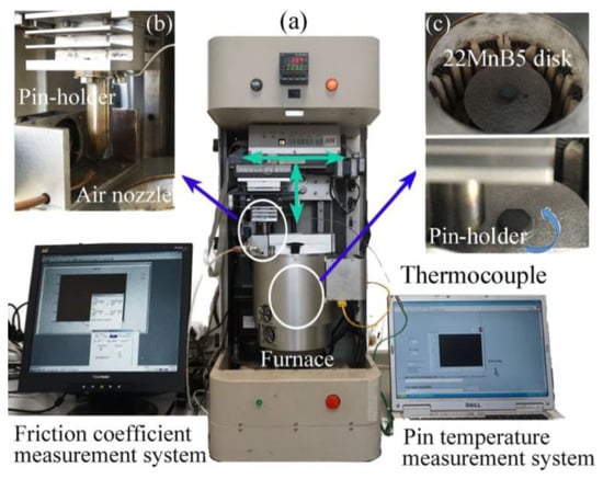
Figure 2.
(a) UMT-3 tribometer; (b) pin cooling system; (c) heating chamber.
For the sake of keeping the same thermal conditions characterizing the actual hot stamping process by partition heating, an air nozzle is used to cool down the pin outside the chamber (see Figure 2b) after a predefined amount of cycles. The pin cooling rate can be adjusted by changing the air pressure air up to eight bars. More details about the testing equipment can be found in [22,24].
3.3. Thermal Simulation Tests
Different heating temperatures are expected to change the morphology and chemical composition of the Al–Si coating, which may lead to different tribological behavior and wear mechanisms. To this regard, thermal simulation tests were firstly performed using the furnace of the UMT-3 tribometer in order to investigate the influence of the heating temperature on the evolution of the Al–Si coating. The experimental plan is shown in Table 2. Three different temperatures were chosen relevant of the hot stamping process by partition heating: 700 °C, where no austenitization occurs as demonstrated in [3,28], and is therefore indicative of the blank temperature in the low-temperature region; 900 °C, where a fully austenitization occurs, and therefore indicative of the blank condition in the high-temperature region; and 800 °C, where the blank is partially austenitized, on behalf of the transition region [3,28].

Table 2.
Experimental plan of the thermal simulation tests.
During the tests, a rectangular blank with a length of 20 mm and width of 5 mm is placed inside the furnace, pre-heated at the target temperature, and held for 6 min. Then the blank is taken out and quenched in water to cool it down to room temperature. Afterwards, the blank section is polished to carry out SEM and EDX analyses of the coating in the thickness direction. Furthermore, the surface morphology of the coating is analyzed through SEM and 3D profiler.
3.4. Wear Tests
Before starting each wear tests, the pin and the blank are cleaned in ether using an ultrasonic cleaner and then air dried. The weight of the initial pin is measured in order to evaluate its volume and weight variation after different cycles. Afterwards, the pin is installed on the pin holder, whereas the blank is fixed on the rotation table inside the furnace. Table 3 reports the wear testing parameters, which reproduce the same thermal and mechanical conditions of the actual hot stamping process by partition heating.

Table 3.
Experimental plan of the wear tests.
The procedure applied for wear testing is as follows: after the furnace reaches the set temperature, the pin enters into the furnace and is brought into contact with the blank at a normal contact pressure equal to 7 MPa, meanwhile the blank is made to rotate reaching a tangential velocity under the pin of 15 mm/s for 5 s. Afterwards, the pin is moved out from the furnace and cooled down for 15 s by the air nozzle. The same steps are repeated until the end of the test.
After repeating the process 100 times, the sliding track is changed in order to make the pin come in contact with new blank surface and virgin coating. It is worth noting that the disk rotating velocity must be adjusted when changing the sliding track in order to keep the same sliding speed. For every disk, four sliding tracks, each used for 400 cycles, are performed and then a new disk is installed. After 200, 400, 1200, and 2000 cycles, the pin is dismounted and cleaned in ether. Then, its weight is measured, and its surface condition evaluated using SEM, EDX, and 3D optical profiler analyses.
4. Results and Discussion
4.1. Chemical and Morphological Evolution of the Al–Si Coating
The SEM images of the cross sections of the blanks after the thermal simulation tests at 700 °C, 800 °C, and 900 °C are shown in Figure 3 together with the results of the EDX micro-chemical analysis.
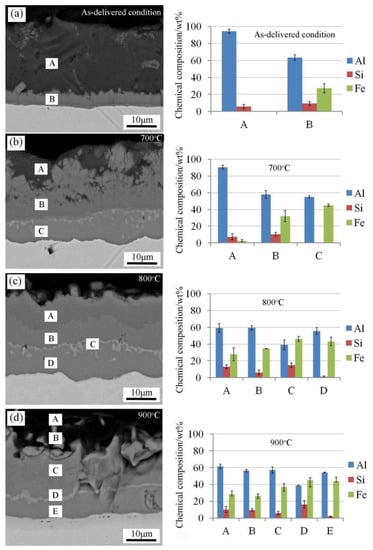
Figure 3.
Morphology and chemical composition of the Al–Si coating heated at different temperatures: (a) as-delivered condition, (b) 700 °C, (c) 800 °C, and (d) 900 °C.
A clear influence of the heating temperature on the evolution of the Al–Si coating can be appreciated. The coating of the blank in as-delivered condition presents two zones: (A) the Al–Si coating, and (B) the interface area between the steel substrate and the coating. This interface zone is made of a ternary mixture containing approximately 64% aluminum, 9% silicon, and 27% iron. The coating of the blank heated at 700 °C presents instead three zones: (A) characterized by the presence of iron, contrary to the as-delivered condition, proving that iron starts diffusing from the interface area to the coating; (B) with a higher presence of iron; and (C) close to the substrate with the highest amount of iron. When the blank is heated at 800 °C, the coating shows four zones: (A), (B), and (C) are characterized by a higher amount of iron compared to the 700 °C sample whereas zone (D) close to the substrate presents a little amount of silicon. When the blank is heated to 900 °C, the number of layers continues increasing and the coating is composed of approximately 5 zones (A–E). In these five zones, the lowest amount of the aluminum is 39% in zone D and the lowest silicon amount is 2% in zone E, which is the same of the 800 °C blank.
Figure 4 shows the SEM images and 3D profiler maps of the coating tested at different temperatures, carried out on the central zone of 50 × 50 mm samples, with a repeatability of three. After the thermal cycle at 700 °C, several peaks appear on the surface, making the coating rougher than in the as-delivered condition, with the surface roughness Sa equal to 4.87 µm (±0.35; Figure 4b). If the holding temperature is increased up to 800 °C, the density and dimension of these peaks decrease, and the surface roughness Sa decreases to 2.73 µm (±0.32; Figure 4c). Whereas at 900 °C, only a few peaks can be observed, but in some zones the coating becomes thinner and distributed in a less homogeneous way, resulting in the surface roughness Sa equal to 4.36 µm (±0.28; Figure 4d). The variation of the coating surface topography can be attributed to the chemical diffusion of iron [23].
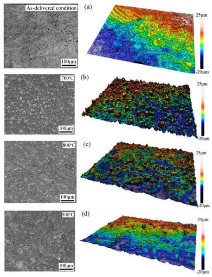
Figure 4.
Scanning electron microscopy (SEM) images and 3D profiler maps of the coating surface heated at different temperatures: (a) as-delivered condition, (b) 700 °C, (c) 800 °C, and (d) 900 °C.
4.2. Friction Coefficient
The temperature history of the pins tested at 700 °C, 800 °C and 900 °C is shown by Figure 5a. It can be seen that the temperature reaches a steady state after 200 s, then a reproducible thermal cycle is kept, where the heating and cooling steps are basically consistent with the actual hot stamping process. The maximum temperature reached by the pin when heating the disk at the three different temperatures are 209 °C, 228 °C, and 268 °C, respectively. This simulates the tools behaviour in hot stamping by partition heating where each segment reaches a different maximum temperature. As in all the tested conditions the pin temperature does not exceed 300 °C, it is possible to assume negligible hardness loss effects, as is decrease from 51 ± 1.5 HRC at room temperature to 49 ± 1.5 HRC at 300 °C [24].
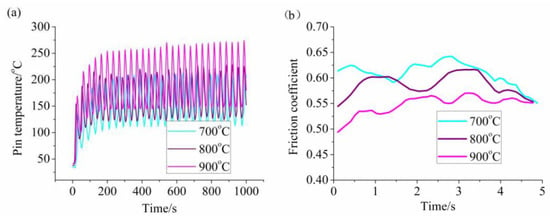
Figure 5.
(a) Evolution of the pin temperature and (b) friction coefficient with time at varying temperature.
The friction coefficient during the test is evaluated according to the Coulomb’s law as in Equation (1):
where is the horizontal force and the vertical one acquired by the strain gauge sensors, is the shear stress, the normal stress, and the apparent contact area. The variation of the friction coefficient obtained every 200 cycles when the disk is heated at 700 °C, 800 °C, and 900 °C is shown in Figure 5b. The friction coefficient decreases at increasing heating temperature, with mean values of the friction coefficient equal to 0.609 (±0.022), 0.591 (±0.020), and 0.547 (±0.018) at 700 °C, 800 °C, and 900 °C, respectively. On one hand, the shear strength of the coating becomes lower at increasing heating temperatures, thus resulting in the decrease of the friction coefficient. On the other hand, more oxidation occurs at increasing heating temperatures, and the oxide particles may play the function of lubricants, therefore causing the reduction of the friction coefficient.
Figure 6 shows the SEM images of the blank and the pin after 200 cycles as a function of the test temperature. It can be seen that the blanks surfaces tested at 800 °C (Sa = 6.25 μm) and 900 °C (Sa = 10.88 μm) have a similar appearance, but are less rough than the one of the disk tested at 700 °C (Sa = 16.33 μm), keeping the same trend described in Figure 4, before the wear tests. Furthermore, the asperities that characterize the heated disk surface are easier to deform at a higher temperature, thus producing a smoother sliding surface. In regards to the surface of the pins, a similar phenomenon can be observed. Massive material adheres to the surface of the pin tested at 700 °C, whereas the surface of the pin tested at 900 °C is very smooth. The more significant surface flattening for both the blank and the pin at the highest heating temperature can also explain the reduction of the friction coefficient at increasing temperature.
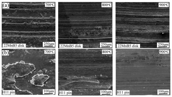
Figure 6.
SEM images of the disks (a) and the pins (b) after 200 cycles when tested at different temperatures.
4.3. Wear Mechanisms
The wear mechanisms arising on the pins tested at different temperatures at increasing sliding cycles were identified through SEM, EDX micro-chemical, and 3D profiler analyses, as well as measurements of the pins weight. Figure 7 shows the SEM images and EDX analysis on the pins surface tested at 700 °C, 800 °C, and 900 °C after 200 cycles. For the pin tested at 700 °C, the bright areas consist of only chromium and iron, whereas oxygen, aluminum and silicon are also present in the dark areas, which were transferred to the pin surface from the blank coating. At the testing temperature of 800 °C the observations confirm the results already found in [24], where aluminum can be found in both the analyzed points 1 and 2, but with a content of aluminum in spectrum 2 higher than that in spectrum 1. When the pin is tested at 900 °C, the content of oxygen in the dark areas reaches values up to 40.81%, which was much higher when compared with the pins tested at 700 °C and 800 °C, proving that oxidation increases at increasing heating temperatures. The EDX analysis indicates that adhesion wear occurred on the pins regardless of the testing temperature, witnessed by the presence of chemical elements of the blank coating. However, the content of silicon on the dark area of the pin tested at 700 °C was 8.33%, which was much higher than that of the pins tested at 800 °C and 900 °C; therefore when a larger amount of the blank coating is transferred to the pin surface then the adhesion wear seems to be severe at the lowest testing temperature.
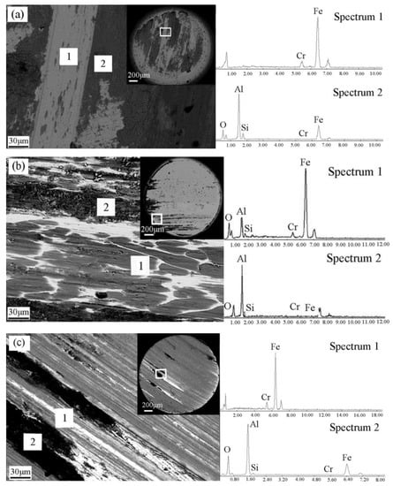
Figure 7.
SEM images and energy-dispersive x-ray (EDX) analysis of the pin surfaces after 200 cycles when tested at: (a) 700 °C, (b) 800 °C [24], and (c) 900 °C.
As the number of cycles were increased at 400, 1200, and 2000, cycle the contact surfaces of the pin cycles were observed and analyzed by means of SEM images and 3D profiler maps, as shown in Figure 8 for the different testing temperatures. The pins tested at 700 °C show severe adhesion as reported in Figure 8a with a large amount of material from the blank coating attached to the pin surface after 400 cycles. Then the amount of adhered material gradually decreased as it was removed by the mutual sliding with the blank as the number of cycles increased. When the testing cycles reached 2000, few scratches appeared, showing that adhesion and abrasive wear phenomena occur simultaneously. The wear mechanisms changed at higher testing temperatures, as already found by Ghiotti et al. [24], at 800 °C, and shown by Figure 8b where more scratches are evident without any massive adhesion as seen on the surface of the pin tested at 700 °C. The same behaviour became more evident at 900 °C (Figure 8c) and can be attributed to the formation of more oxidation particles at an elevated temperature. These wear particles can act as a three-body abradant between two contacting surfaces or a two-body abradant embedded on one surface, resulting in the abrasive damage of the surfaces. Furthermore, the surface of the pin tested at 900 °C was smoother and showed more shallow scratches compared with the pin tested at 800 °C. However, the variations of the pin weight after different numbers of cycles shown by Figure 9b highlight how the abrasive wear is more severe at the higher temperature, as the weight loss is greater at 900 °C. This difference of the surface conditions may be related to the characteristics of the oxidation particles at the different testing temperatures, as the presence of more severe scratches seems to be related to the presence of bigger and harder three-body abradant particles.
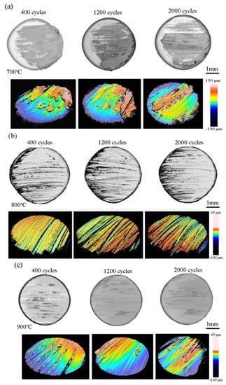
Figure 8.
Topography of the pin surfaces at increasing numbers of cycles when testing at (a) 700 °C, (b) 800 °C [24], and (c) 900 °C.
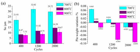
Figure 9.
Surface roughness Sa (a) and weight variation (b) of the pins tested at different temperatures and measured after 400, 1200, and 2000 cycles.
Figure 9a,b show the surface roughness Sa and weight variation of the pins at the tree temperatures after 400, 1200, and 2000 cycles, respectively. The results confirm the evolution of the wear mechanisms as described above. The surface roughness basically increased with the cycle number, but it was larger at the lowest temperature due to the adhesive wear that took places at 700 °C, which causes the increase of the surface roughness due to the material transfer from the blank. The analysis of the pin weight variation at varying numbers of cycles leads to similar conclusions, as at 700 °C the pin is heavier after 400 and 1200 cycles when compared with the initial one. This indicates that adhesive wear is the main wear mechanism at the lowest temperature. For the pin tested at 800 °C, the weight showed a small increment after 400 cycles, but then it decreased after 1200 and 2000 cycles, proving that adhesive and abrasive wear occur simultaneously. However, the weight of the pin tested at 900 °C always decreased across increasing number of cycles, showing that abrasive wear always plays the dominating role at the highest temperature.
5. Conclusions
Thermal simulation tests and wear tests, replicating the same thermal and mechanical cycles characterizing the hot stamping process by partition heating, were performed to investigate the influence of the heating temperature on the evolution of the Al–Si coating and the wear mechanisms. The following main conclusions can be drawn from this study.
- When heating the metal blank, iron from the substrate gradually diffuses to the Al–Si coating surface, forming a more complex structure as the heating temperature increases.
- The surface topography of the Al–Si coating changes at different heating temperatures, becoming rougher as a consequence of the formation of peaks than the as-delivered condition; however, the surface roughness decreases when the heating temperature increases from 700 °C to 900 °C.
- The friction coefficient decreases at increasing heating temperatures, as a consequence of both the lower shear strength of the coating and the presence of more and softer oxidation particles at higher temperatures.
- Adhesive wear seems to be dominant at 700 °C while abrasive wear becomes more relevant as the temperature increases. This behaviour is proven by the analysis carried out on the material transferred from the Al–Si blank coating to the pin surface.
- The SEM images, 3D profiler maps, surface roughness, and weight variation of the pins after different number of cycles demonstrate the difference in the wear mechanisms at different heating temperatures: adhesive wear is the primary wear mechanism at the lowest testing temperature, whereas abrasive wear plays a more dominating role at higher temperatures.
Author Contributions
Investigation, Y.M. and M.S.; Supervision, A.G.; Writing—original draft, Y.M.; Writing—review and editing, E.S. All authors have read and agreed to the published version of the manuscript.
Funding
This study was supported by the National Natural Science Foundation of China (Grant No. 51705018 and U1564202) and China Scholarship Council (Grant No. 201706460070).
Conflicts of Interest
The authors declare no conflict of interest.
References
- Karbasian, H.; Tekkaya, A.E. A review on hot stamping. J. Mater. Process. Technol. 2010, 210, 2103–2118. [Google Scholar] [CrossRef]
- Borsetto, F.; Ghiotti, A.; Bruschi, S. Investigation of the high strength steel Al-Si coating during hot stamping operations. Key Eng. Mater. 2009, 410–411, 289–296. [Google Scholar] [CrossRef]
- Mori, K.; Bariani, P.F.; Behrens, B.A.; Brosius, A.; Bruschi, S.; Maeno, T.; Merklein, M.; Yanagimoto, J. Hot stamping of ultra-high strength steel parts. CIRP Ann. 2017, 66, 755–777. [Google Scholar] [CrossRef]
- Merklein, M.; Wieland, M.; Lechner, M.; Bruschi, S.; Ghiotti, A. Hot stamping of boron steel sheets with tailored properties: A review. J. Mater. Process. Technol. 2016, 228, 11–24. [Google Scholar] [CrossRef]
- Merklein, M.; Johannes, M.; Lechner, M.; Kuppert, A. A review on tailored blanks production, application and evaluation. J. Mater. Process. Technol. 2014, 214, 151–164. [Google Scholar] [CrossRef]
- George, R.; Bardelcik, A.; Worswick, M.J. Hot forming of boron steels using heated and cooled tooling for tailored properties. J. Mater. Process. Technol. 2012, 212, 2386–2399. [Google Scholar] [CrossRef]
- Mori, K.; Maeno, T.; Mongkolkaji, K. Tailored die quenching of steel parts having strength distribution using bypass resistance heating in hot stamping. J. Mater. Process. Technol. 2013, 213, 508–514. [Google Scholar] [CrossRef]
- Mu, Y.H.; Wang, B.Y.; Zhou, J.; Kang, Y.; Li, X.T. Heating parameters optimization of hot stamping by partition heating for tailored properties. ISIJ Int. 2017, 57, 1442–1450. [Google Scholar] [CrossRef]
- Mu, Y.H.; Wang, B.Y.; Zhou, J.; Huang, X.; Li, X.T. Hot stamping of boron steel using partition heating for tailored properties: Experimental trials and numerical analysis. Metall. Mater. Trans. A 2017, 48, 5467–5479. [Google Scholar] [CrossRef]
- Mu, Y.H.; Zhou, J.; Wang, B.Y.; Wang, Q.L.; Ghiotti, A.; Bruschi, S. Numerical simulation of hot stamping by partition heating based on advanced constitutive modelling of 22MnB5 behaviour. Finite Elem. Anal. Des. 2018, 147, 34–44. [Google Scholar] [CrossRef]
- Ghiotti, A.; Bruschi, S.; Borsetto, F. Tribological characteristics of high strength steel sheets under hot stamping conditions. J. Mater. Process. Technol. 2011, 211, 1694–1700. [Google Scholar] [CrossRef]
- Pelcastre, L.; Hardell, J.; Rolland, A.; Prakash, B. Influence of microstructural evolution of Al-Si coated UHSS on its tribological behavior against tool steel at elevated temperatures. J. Mater. Process. Technol. 2016, 228, 117–124. [Google Scholar] [CrossRef]
- Gui, Z.X.; Liang, W.K.; Liu, Y.; Zhang, Y.S. Thermo-mechanical behavior of the Al-Si alloy coated hot stamping boron steel. Mater. Des. 2014, 60, 26–33. [Google Scholar] [CrossRef]
- Wang, K.; Jin, Y.M.; Zhu, B.; Zhang, Y.S. Investigation on cracking characteristics of Al-Si coating on hot stamping boron steel parts based on surface strain analysis. Surf. Coat. Technol. 2017, 309, 282–294. [Google Scholar] [CrossRef]
- Pelcastre, L.; Hardell, J.; Herrera, N.; Prakash, B. Investigation into the occurrence of galling during hot forming of Al-Si-coated high-strength steel. Proc. Inst. Mech. Eng. Part J J. Eng. Tribol. 2010, 225, 487–498. [Google Scholar] [CrossRef]
- Kondratiuk, J.; Kuhn, P. Tribological investigation on friction and wear behavior of coatings for hot sheet metal forming. Wear 2011, 270, 839–849. [Google Scholar] [CrossRef]
- Mu, Y.H.; Wang, B.Y.; Huang, M.D.; Zhou, J.; Li, X.T. Investigation on tribological characteristics of boron steel 22MnB5-tool steel H13 tribopair at high temperature. Proc. Inst. Mech. Eng. Part J J. Eng. Tribol. 2017, 231, 165–175. [Google Scholar] [CrossRef]
- Boher, C.; Le Roux, S.; Penazzi, L.; Dessain, C. Experimental investigation of the tribological behavior and wear mechanisms of tool grades in hot stamping of a high-strength boron steel. Wear 2012, 294–295, 286–295. [Google Scholar] [CrossRef]
- Venema, J.; Matthews, D.T.A.; Hazrati, J.; Wormann, J.; Van den Boogaard, A.H. Friction and wear mechanisms during hot stamping of Al-Si coated press hardening steel. Wear 2017, 380–381, 137–145. [Google Scholar] [CrossRef]
- Tian, X.W.; Zhang, Y.S.; Li, J. Investigation on tribological behavior of advanced high strength steels: Influence of hot stamping process parameters. Tribol. Lett. 2012, 45, 489–495. [Google Scholar] [CrossRef]
- Azushima, A.; Uda, K.; Yanagida, A. Friction behavior of aluminium-coated 22MnB5 in hot stamping under dry and lubricated conditions. J. Mater. Process. Technol. 2012, 212, 1014–1021. [Google Scholar] [CrossRef]
- Ghiotti, A.; Bruschi, S.; Medea, F.; Hamasaiid, A. Tribological behavior of high thermal conductivity steels for hot stamping tools. Tribol. Int. 2016, 97, 412–422. [Google Scholar] [CrossRef]
- Ghiotti, A.; Bruschi, S.; Sgarabotto, F.; Bariani, P.F. Tribological performances of Zn-based coating in direct hot stamping. Tribol. Int. 2014, 78, 142–151. [Google Scholar] [CrossRef]
- Ghiotti, A.; Sgarabotto, F.; Bruschi, S. A novel approach to wear testing in hot stamping of high strength boron steel sheets. Wear 2013, 302, 1319–1326. [Google Scholar] [CrossRef]
- Ghiotti, A.; Bruschi, S.; Medea, F. Comparison of tribological and wear performances of Al-Si and Zn coatings in hot stamping of boron steel sheets. Wear 2015, 332–333, 810–821. [Google Scholar] [CrossRef]
- Boeke, J.; Krogmeier, J.; Reinhold, P. Continuous Furnace Used in the Production of Vehicle Components, e.g. B-Columns, Comprises Two Zones Lying Opposite Each Other and Separated from Each Other by a Thermal Insulating Separating Wall. Germany Patent Number DE10256621B3, 3 December 2002. [Google Scholar]
- Sagar, V.R.; Wärmerfjord, K.; Söderberg, R. Geometrical variation from selective laser heat treatment of boron steel. Porc. Cirp 2018, 75, 409–414. [Google Scholar] [CrossRef]
- Svec, T.; Merklein, M. Hot Stamping—Process Window for the Auste- nitization of Dualphase Steel. In Proceedings of the 4th International Conference on Hot Sheet Metal Forming of High-Performance Steel, Lulea, Sweden, 9–12 June 2013; pp. 275–282. [Google Scholar]
© 2020 by the authors. Licensee MDPI, Basel, Switzerland. This article is an open access article distributed under the terms and conditions of the Creative Commons Attribution (CC BY) license (http://creativecommons.org/licenses/by/4.0/).