Prediction of Plate Crown during Aluminum Hot Flat Rolling by Finite Element Modeling


Abstract
:1. Introduction
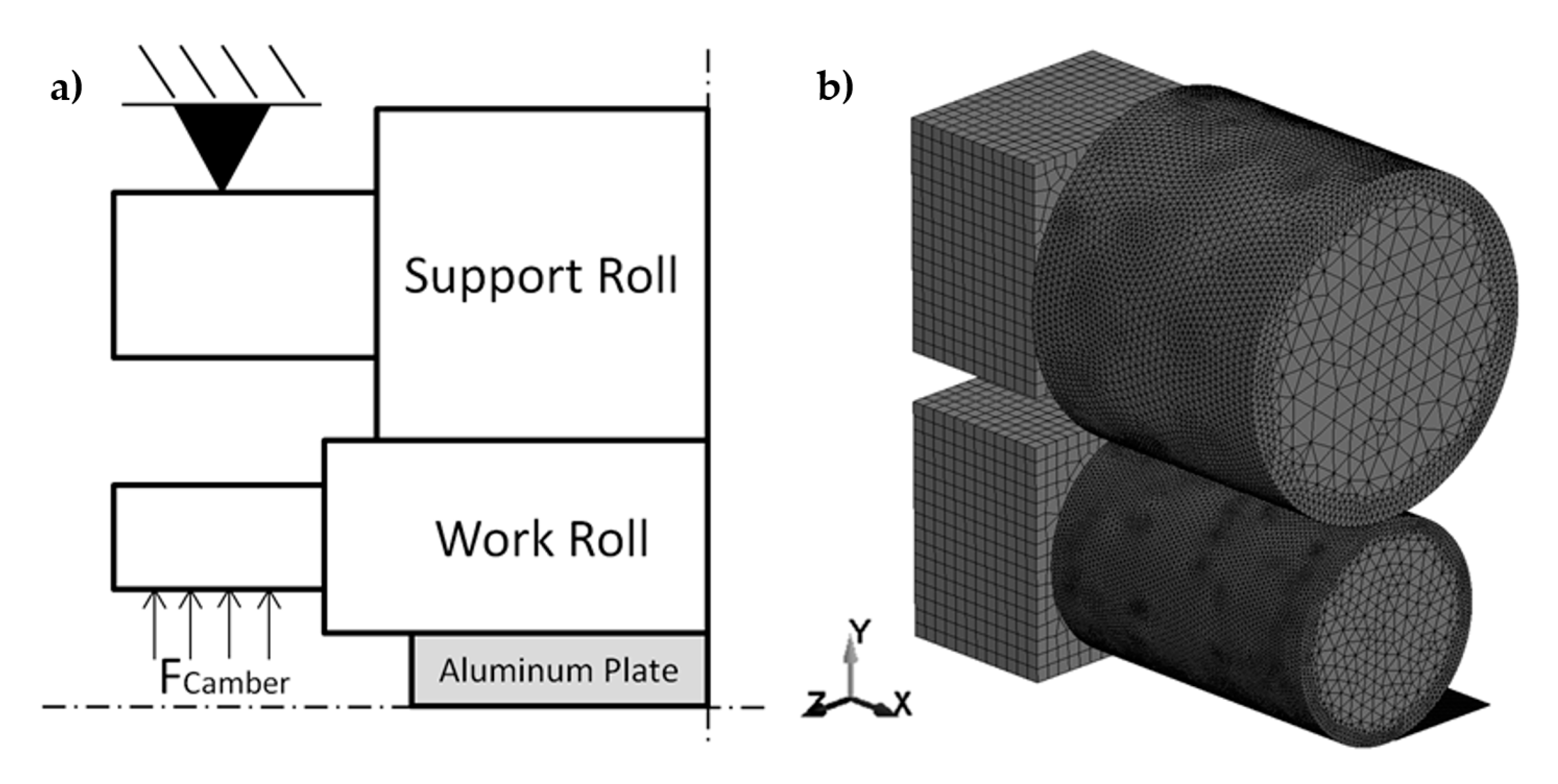
2. Simulation Model
3. Simulation Results
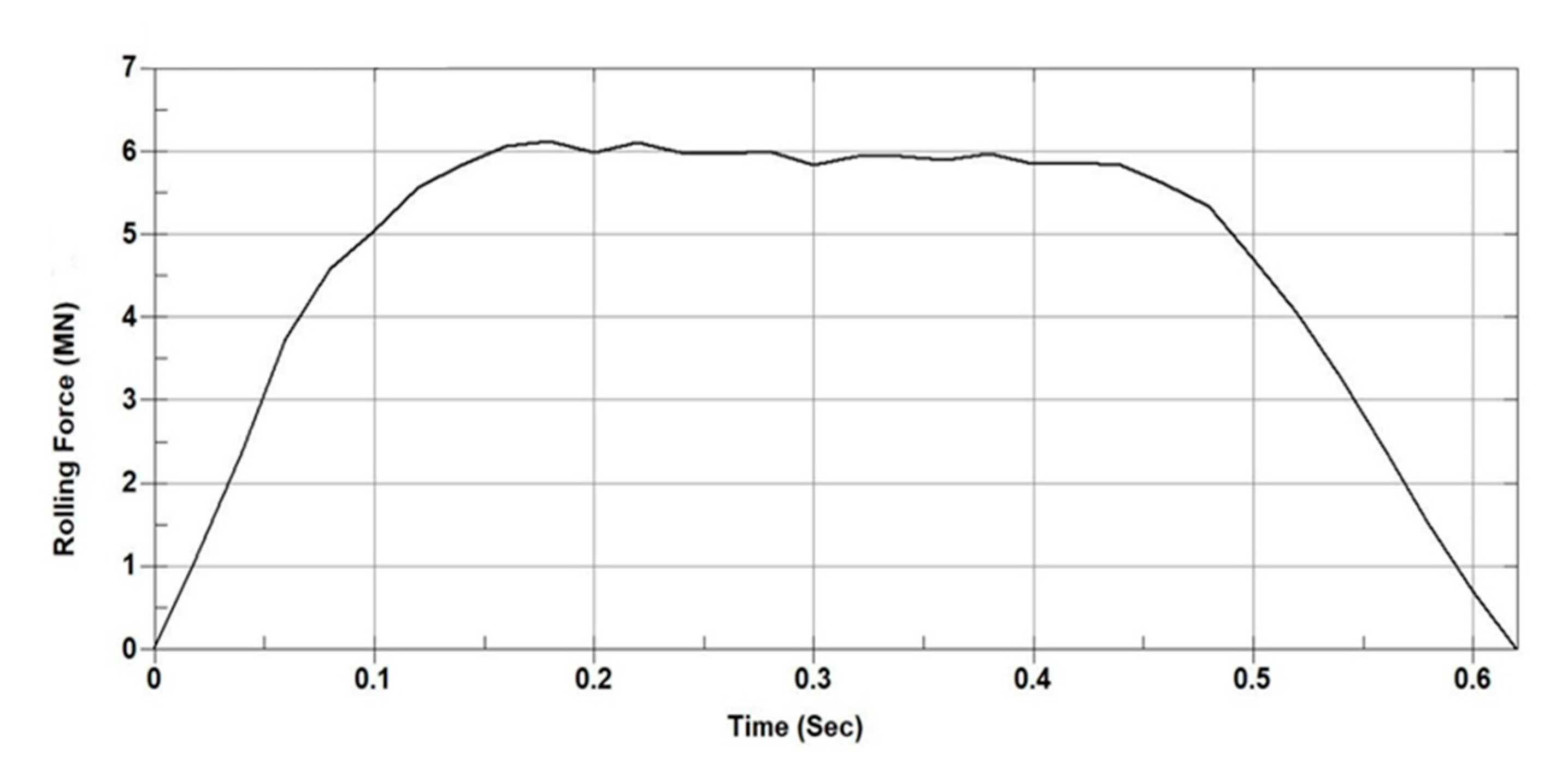
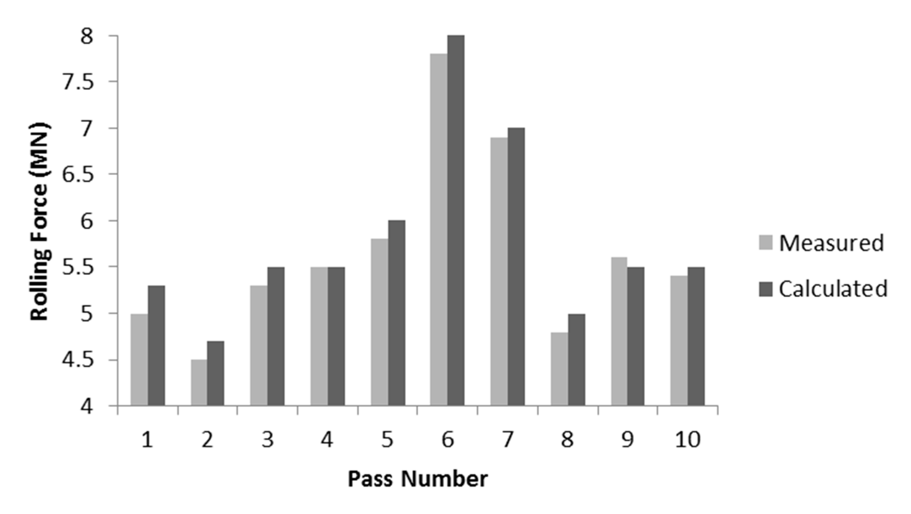
3.1. Force Calculation
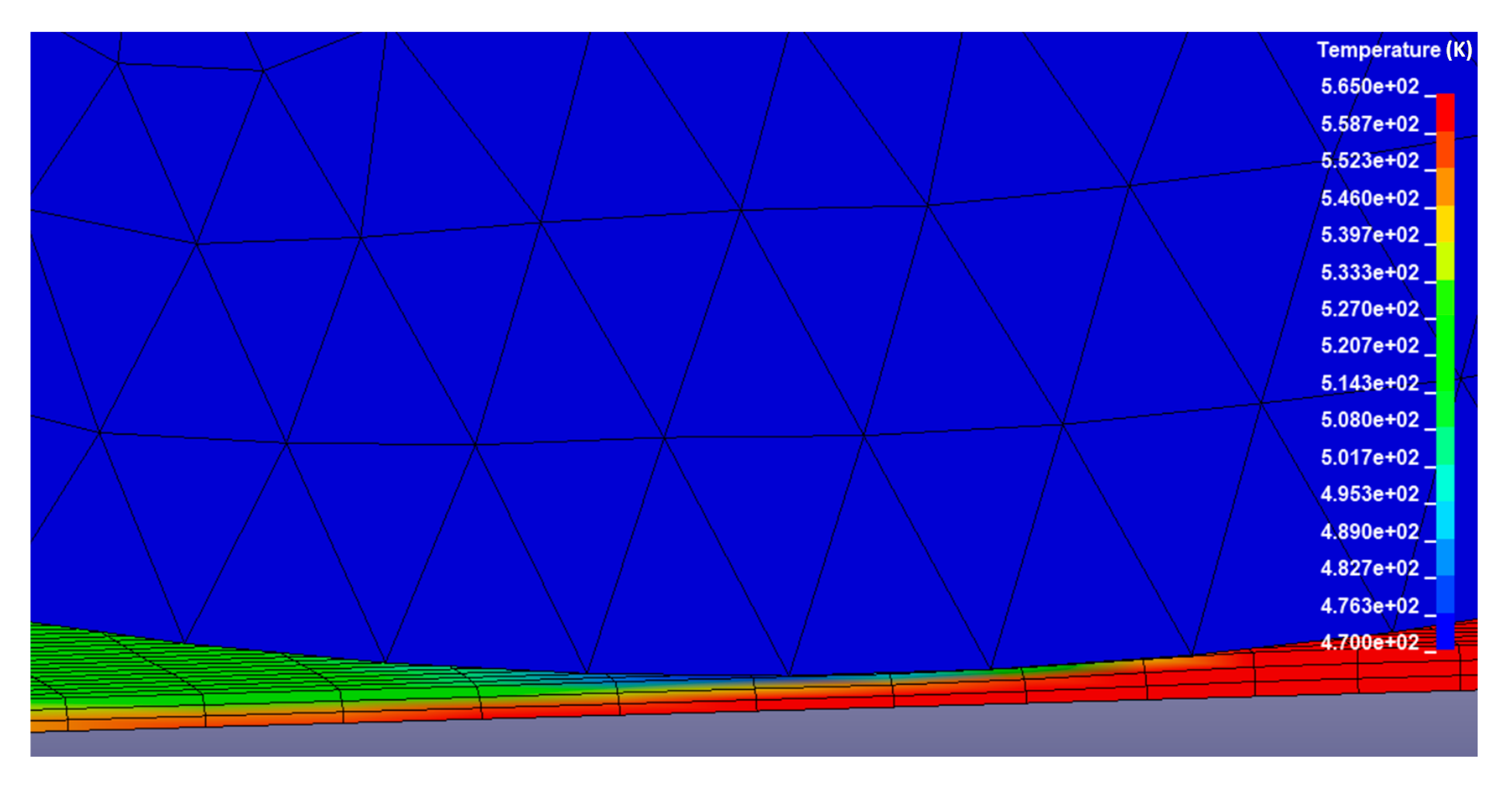
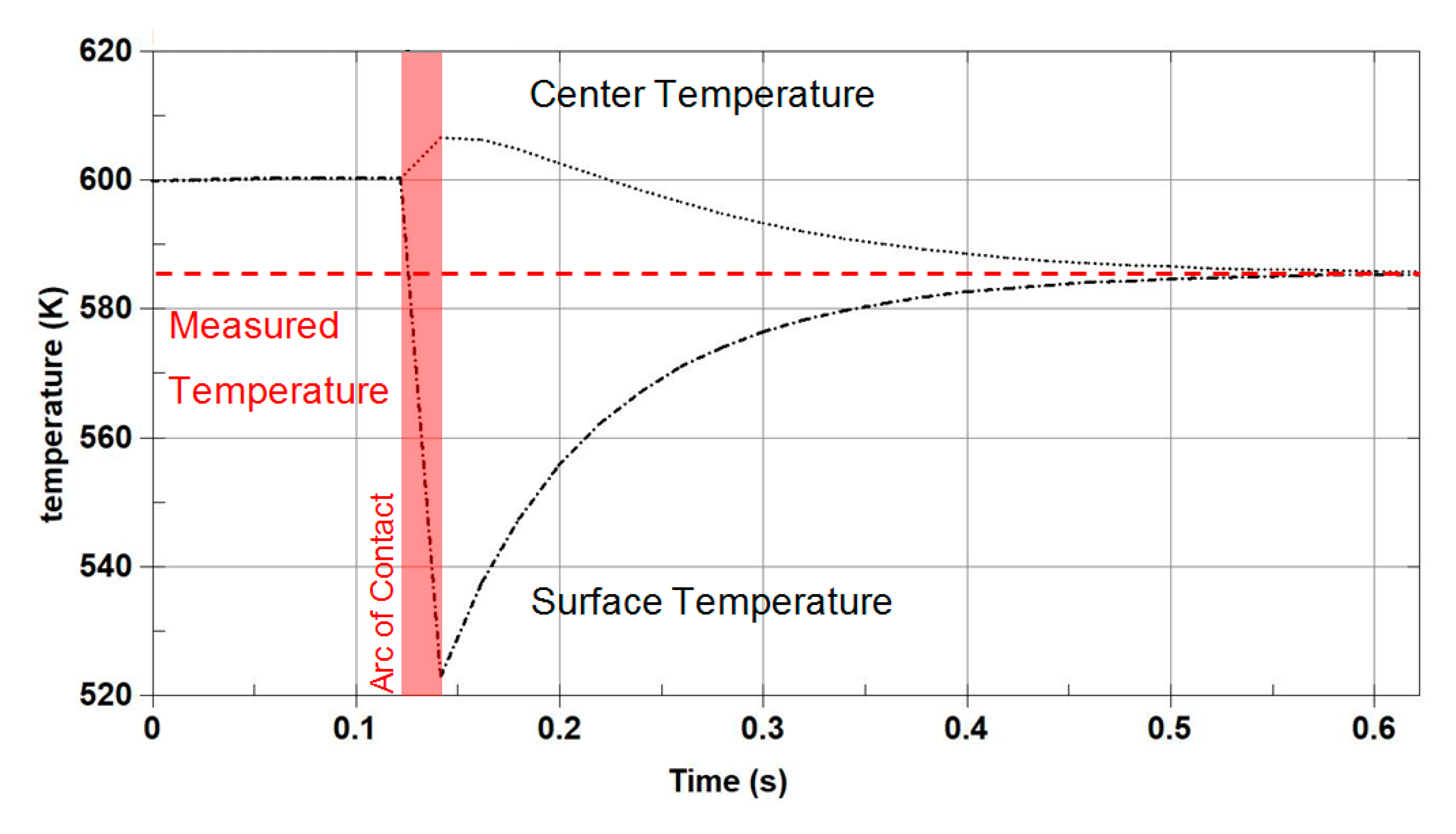
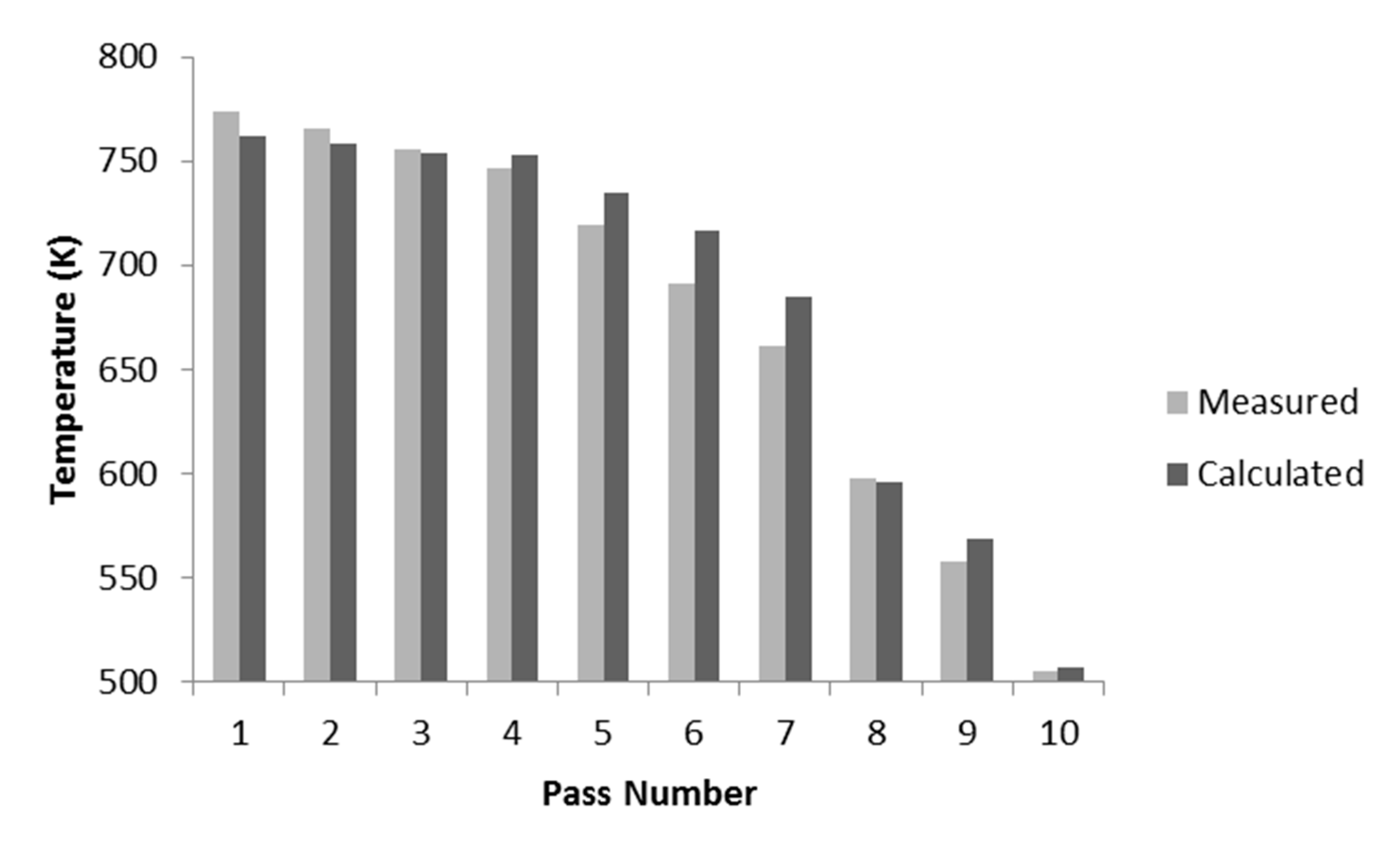
3.2. Thermal Analysis
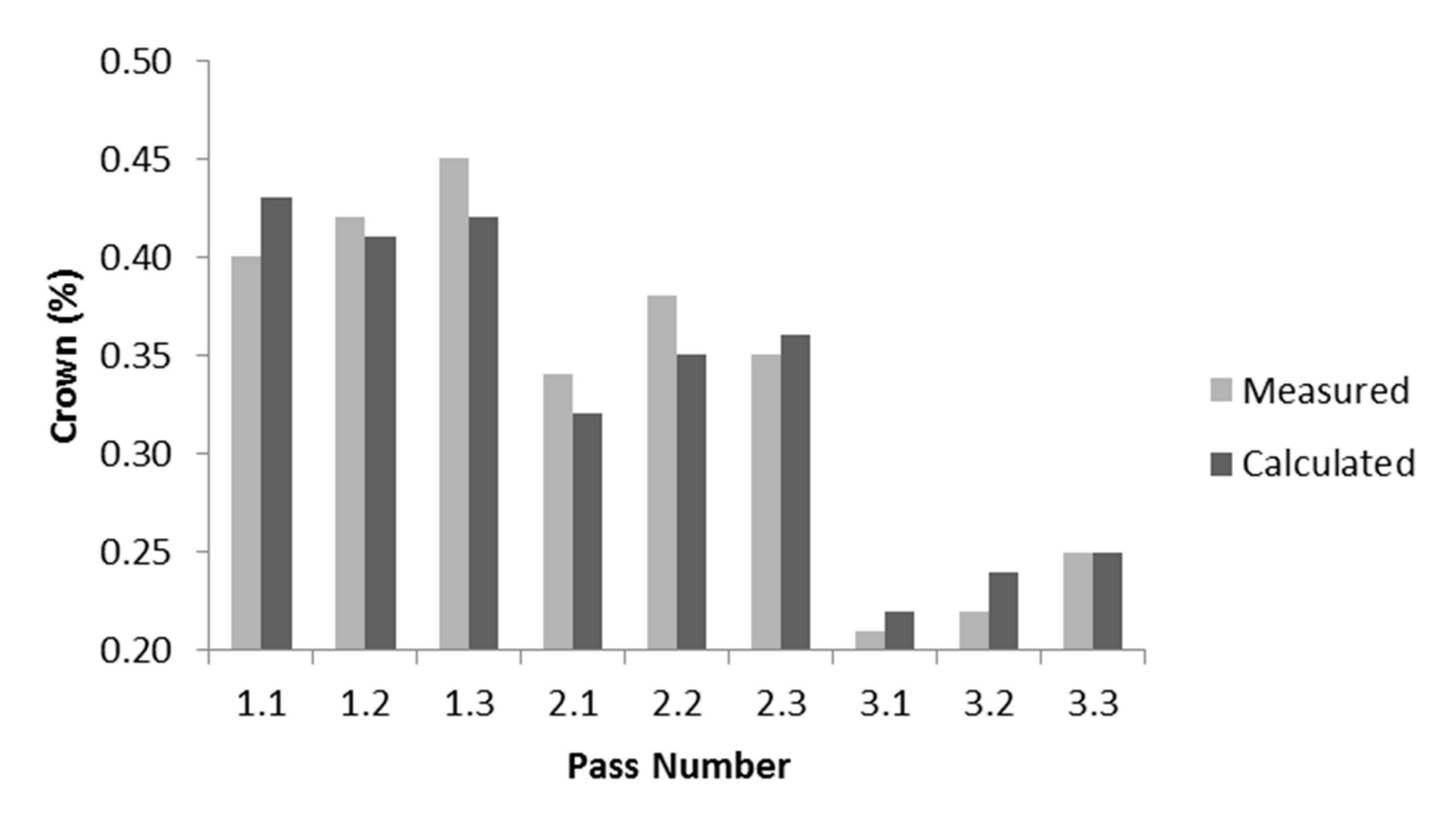
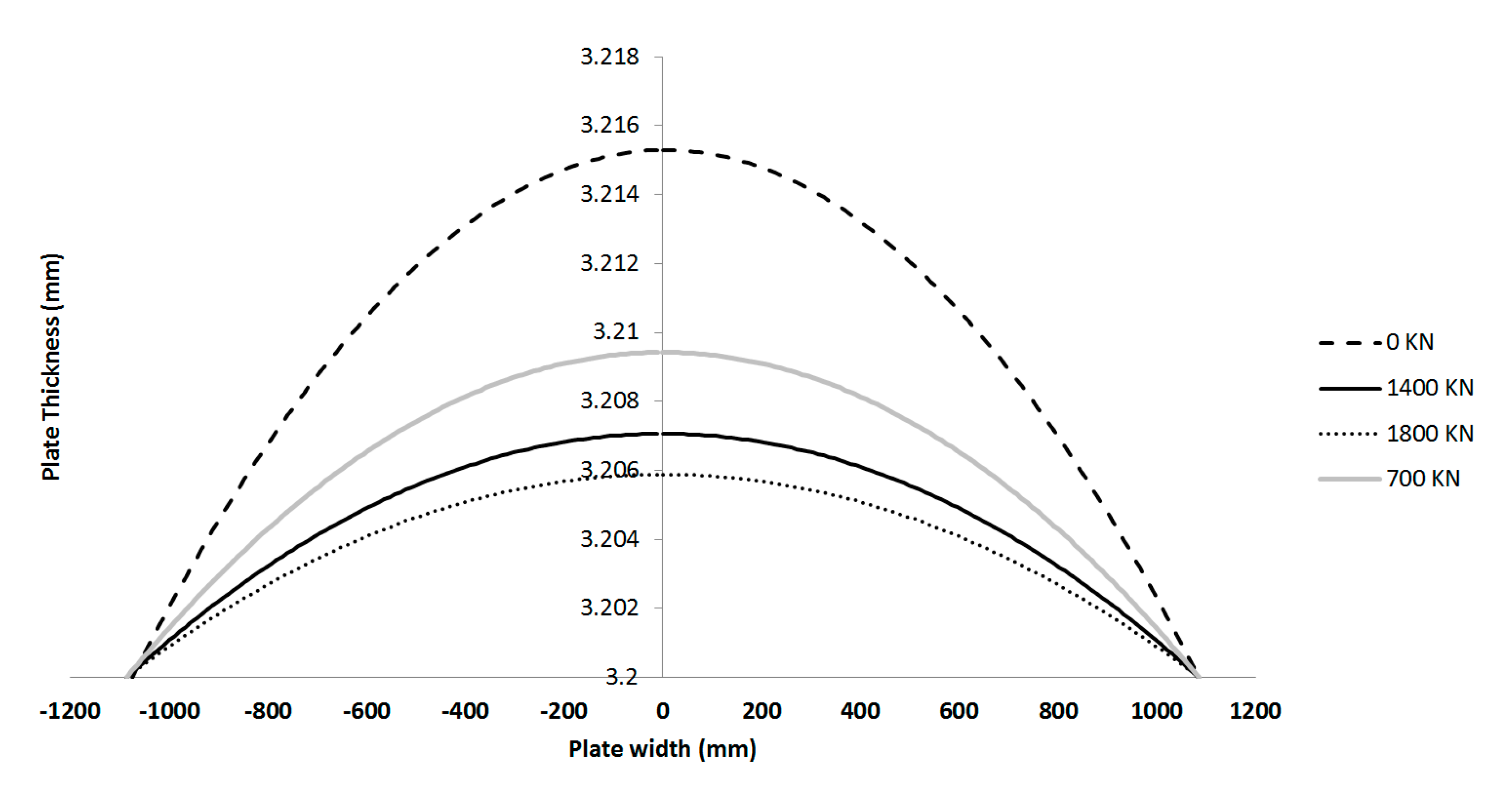
3.3. Profile Prediction
3.4. Discussion
4. Conclusions
Author Contributions
Funding
Acknowledgments
Conflicts of Interest
References
- Liu, C.; He, A.; Qiang, Y.; Guo, D.; Shao, J. Effect of Internal Stress of Incoming Strip on Hot Rolling Deformation Based on Finite Element and Infinite Element Coupling Method. Metals 2018, 8, 92. [Google Scholar] [CrossRef]
- Sato, M.; Kuchi, M. Profile and Flatness Set Up System for Rolling Mill. IHI Eng. Rev. 2009, 42, 26–31. [Google Scholar]
- Sun, W.Q.; Li, B.; Shao, J.; He, A.R. Research on crown and flatness allocation strategy of hot rolling mills. Int. J. Simul. Model. 2016, 12, 327–340. [Google Scholar] [CrossRef]
- Nandan, R.; Rai, R.; Jayakanth, R.; Moitra, S.; Chakraborti, N.; Mukhopadhyay, A. Regulating Crown and Flatness during Hot Rolling: A Multiobjective Optimization Study Using Genetic Algorithms. Mater. Manuf. Process. 2005, 20, 459–478. [Google Scholar] [CrossRef]
- Cawthorna, C.J.; Loukaides, E.G.; Allwood, J.M. Comparison of analytical models for sheet rolling. Procedia Eng. 2014, 81, 2451–2456. [Google Scholar] [CrossRef]
- Szűcs, M.; Krállics, G.; Lenard, J. A Comparative Evaluation of Predictive Models of the Flat Rolling Process. Periodica Polytech. Mech. Eng. 2018, 62, 165–172. [Google Scholar] [CrossRef]
- Domanti, S.A.; Edwards, W.J.; Thomas, P.J.; Chefneux, I.L. Application of foil rolling models to thin steel strip and temper rolling. In Proceedings of the International Rolling Conference on Flat Products, Dusseldorf, Germany, 20–22 June 1994; pp. 1–8. [Google Scholar]
- Kang, Y.; Jang, Y.; Choi, Y.; Lee, D.; Won, S. An Improved Model for Camber Generation During Rough Rolling Process. ISIJ Int. 2015, 55, 1980–1986. [Google Scholar] [CrossRef]
- Lee, S.H.; Song, G.H.; Lee, S.J.; Kim, B.M. Study on the improved accuracy of strip profile using numerical formula model in continuous cold rolling with 6-high mill. J. Mech. Sci. Technol. 2011, 25, 2101–2109. [Google Scholar] [CrossRef]
- Steinboeck, A.; Ettl, A.; Kugi, A. Dynamical Models of the Camber and the Lateral Position in Flat Rolling. Appl. Mech. Rev. 2017, 69, 040801. [Google Scholar] [CrossRef]
- Fukushima, S.; Washikita, Y.; Sasaki, T.; Nakagawa, S.; Buei, Y.; Yakita, Y.; Yanagimoto, J. High-Accuracy Profile Prediction Model for Mixed Scheduled Rolling of High Tensile Strength and Mild Steel in Hot Strip Finishing Mill; NIPPON STEEL & SUMITOMO METAL TECHNICAL REPORT No. 111; UDC 621. 771. 237. 016. 2: 62–523; Senior Researcher, Integrated Process Research Lab.: Kashima City, Japan, 2016. [Google Scholar]
- Gavalas, E.; Pressas, I.; Papaefthymiou, S. Mesh sensitivity analysis on implicit and explicit method for rolling simulation. Int. J. Struct. Integr. 2018, 9, 465–474. [Google Scholar] [CrossRef]
- Kapil, S.; Eberhard, P.; Dwivedy, S.K. Dynamic Analysis of Cold-Rolling Process Using the Finite-Element Method. J. Manuf. Sci. Eng. 2016, 138, 041002. [Google Scholar] [CrossRef]
- Linghu, K.; Jiang, Z.; Zhao, J.; Li, F.; Wei, D.; Xu, J.; Zhang, X.; Zhao, X. 3D FEM analysis of strip shape during multi-pass rolling in a 6-high CVC cold rolling mill. Int. J. Adv. Manuf. Technol. 2014, 74, 1733–1745. [Google Scholar] [CrossRef]
- Nakhoul, R.; Montmitonnet, P.; Legrand, N. Manifested flatness defect prediction in cold rolling of thin strips. Int. J. Mater. Form. 2015, 8, 283–292. [Google Scholar] [CrossRef]
- Sherstnev, P.; Melzer, C.; Sommitsch, C. Prediction of precipitation kinetics during homogenisation and microstructure evolution during and after hot rolling of AA5083. Int. J. Mech. Sci. 2012, 54, 12–19. [Google Scholar] [CrossRef]
- Simon, P.; Falkinger, G.; Scheiblhofer, S. Hot Rolling Simulation of Aluminium Alloys using LS-Dyna. In Proceedings of the 11th European LS-DYNA Conference, Salzburg, Austria, 9–11 May 2017. [Google Scholar]
- Yoon, S.J.; Shin, T.J.; Lee, J.S.; Hwang, S.M. Three-Dimensional Finite Element Analysis of Skin-Pass Rolling and New Models for Process Control. J. Manuf. Sci. Eng. 2017, 139, 091003. [Google Scholar] [CrossRef]
- Gautam, V. Finite element analysis of deflection of rolls and its correction by providing camber on rolls. Int. J. Res. Aeronaut. Mech. Eng. 2013, 1, 42–47. [Google Scholar]
- Shigaki, Y.; Montmitonnet, P.; Silva, J.M. 3D finite element model for roll stack deformation coupled with a Multi-Slab model for strip deformation for flat rolling simulation. In Proceedings of the AIP Conference Proceedings, Dublin, Ireland, 26–28 April 2017; Volume 1896, p. 190018. [Google Scholar] [CrossRef]
- Acar, D.; Türköz, M.; Gedikli, H.; Halkacı, H.S.; Cora, Ö.N. Warm Hydromechanical Deep Drawing of AA 5754-O and Optimization of Process Parameters. J. Eng. Mater. Technol. 2018, 140, 011012. [Google Scholar] [CrossRef]
- Couch, R.; Becker, R.; Rhee, M.; Li, M. Development of a Rolling Process. Design Tool for Use in Improving Hot Roll Slab Recovery; Lawrence Livermore National Laboratory: Livermore, CA, USA, 2004. [Google Scholar]
- Bagheripoor, M.; Bisadi, H. Effects of rolling parameters on temperature distribution in the hot rolling of aluminum strips. Appl. Ther. Eng. 2011, 31, 1556–1565. [Google Scholar] [CrossRef]


| Work Roll | Value |
|---|---|
| Length (mm) | 3000 |
| Diameter (mm) | 950 |
| Support Roll | |
| Length (mm) | 2500 |
| Diameter (mm) | 1500 |
| Aluminum Strip | Value |
|---|---|
| Poisson’s ratio | 0.33 |
| Young’s modulus [GPa] | 70 |
| A [MPa] | 103 |
| B [MPa] | 296.6 |
| C | 0.4368 |
| n | −0.003101 |
| m | 1.2451299 |
| Steel Rolls | |
| Poisson’s ratio | 0.3 |
| Young’s modulus [GPa] | 200 |
| Aluminum Strip | Value |
|---|---|
| Density [Kg/m3] | 2700 |
| Heat Capacity [J/(kg K] | 904 |
| Thermal Conductivity [W/m K] | 220 |
| Steel Rolls | |
| Density [Kg/m3] | 7800 |
| Heat Capacity [J/(kg K] | 485 |
| Thermal Conductivity [W/m K] | 38 |
| Frictional Boundary | Value |
|---|---|
| coefficient of friction, | 0.4 |
| shear factor, | 0.8 |
| Thermal Boundary | |
| Heat Transfer Coefficient, [KW/m2K] | 100 |
© 2019 by the authors. Licensee MDPI, Basel, Switzerland. This article is an open access article distributed under the terms and conditions of the Creative Commons Attribution (CC BY) license (http://creativecommons.org/licenses/by/4.0/).
Share and Cite
Gavalas, E.; Papaefthymiou, S. Prediction of Plate Crown during Aluminum Hot Flat Rolling by Finite Element Modeling. J. Manuf. Mater. Process. 2019, 3, 95. https://doi.org/10.3390/jmmp3040095
Gavalas E, Papaefthymiou S. Prediction of Plate Crown during Aluminum Hot Flat Rolling by Finite Element Modeling. Journal of Manufacturing and Materials Processing. 2019; 3(4):95. https://doi.org/10.3390/jmmp3040095
Chicago/Turabian StyleGavalas, Evangelos, and Spyros Papaefthymiou. 2019. "Prediction of Plate Crown during Aluminum Hot Flat Rolling by Finite Element Modeling" Journal of Manufacturing and Materials Processing 3, no. 4: 95. https://doi.org/10.3390/jmmp3040095
APA StyleGavalas, E., & Papaefthymiou, S. (2019). Prediction of Plate Crown during Aluminum Hot Flat Rolling by Finite Element Modeling. Journal of Manufacturing and Materials Processing, 3(4), 95. https://doi.org/10.3390/jmmp3040095