1. Introduction
Nickel-based Inconel 625 alloy has numerous applications in the aeronautics, aerospace, marine, chemical, and petrochemical industries [
1,
2]. The alloy is generally used in a medium temperature range (250–593 °C) for structural applications requiring high strength and excellent corrosion resistance, and in a high temperature range (over 593 °C) for applications calling for outstanding creep resistance (ASTM E139-11, ASTM B444). These service properties can be achieved by conventional manufacturing technologies such as forging, rolling, or extrusion [
3,
4,
5,
6]; laser powder bed fusion (LPBF) additive manufacturing (AM) technology, however, offers numerous advantages over conventional manufacturing, more specifically in terms of its ability to fabricate parts with near net shapes, unique designs, added functionalities, low buy-to-fly ratios, and high productivity [
7,
8,
9,
10]. Moreover, LPBF is capable of producing fully functional parts directly from metal powder without the need for specialized tooling and intermediate processing steps.
It should nevertheless be noted that complex heat effects, which occur during LPBF and are related to highly localized multiple melting–remelting of powder and of underlying bulk materials, differ from those seen during conventional casting and welding. They are also responsible for strongly non-equilibrium heat and mass transfer and solidification phenomena leading to grain refinement, texture development, and the formation of unusual metastable phases [
11,
12,
13]. High residual stresses resulting from a combination of significant temperature gradients and high cooling rates represent another peculiarity of LPBF; to avoid distortions and cracking, printed parts must therefore be subjected to post-processing stress relief heat treatment before they can even be removed from the build plate [
14,
15].
To mitigate the undesirable effects of LPBF processing on the microstructure of parts (columnar structure and precipitation formation), various post-processing heat treatments have been proposed [
12,
13,
16,
17]. These treatments frequently differ from those recommended for conventionally processed IN625 alloy parts, because of the previously mentioned structural features related to LPBF processing. For example, only a small amount of recrystallized structure is found in the LPBF IN625 alloy at 980 °C (~0.8 T
m) [
12], while in the conventionally deformed (ε = 0.4) IN625 alloy, annealing in the 900–980 °C temperature range results in full recrystallization [
18]. A fully recrystallized structure has been observed in the LPBF IN625 alloy only at temperatures higher than 1100 °C [
12,
13,
16]. Thus, numerous studies on LPBF-fabricated alloys have aimed to find an original sequence of post-processing heat treatments, which can include solution treatment, homogenization annealing, aging, etc., in order to render the service properties of LPBF parts comparable or superior to those of conventionally manufactured alloys of similar compositions.
An excellent combination of outstanding corrosion resistance and superior creep resistance, as well as the relatively high tensile strength of nickel-based IN625 alloy (up to 600 °C), make it an interesting choice for aerospace applications. It has been shown that post-processing annealing of LPBF IN625 alloy can significantly improve its room temperature ductility as compared to its as-built state [
13,
19,
20,
21]. However, the assessment of mechanical properties cannot solely be limited to room temperature testing, especially for materials dedicated for service at elevated temperatures. In this context, it is known that conventionally processed nickel-based superalloys face the risk of embrittlement at temperatures higher than 600 °C, and that thermal treatments can affect this mechanical behavior either positively or negatively [
22].
It has been shown, for example, that at 538 °C, the mechanical resistance and the elongation to failure of an IN625 alloy that was electron beam-melted and then hot isostatically pressed (HIP, 1120 °C, 100 MPa, 4 h) were close to those of wrought IN625 alloy [
23]. At 760 °C, however, as compared to its wrought counterpart, the laser powder-fused IN625 alloy (HIP under the same conditions as above) manifested significantly lower ductility, but similar mechanical resistance [
16,
24]. Notwithstanding the preceding, such information is very limited, which makes it difficult to compare the tensile properties of printed and wrought IN625 parts. The outstanding creep resistance of wrought IN625 alloy favors its use at elevated temperatures, but, as was the case with the tensile properties, we could not find any publicly available information on the creep properties of 3D-printed IN625 alloy.
Unlike IN625 alloy, LPBF IN718 alloy, as a precipitation-hardened alloy with a higher mechanical resistance at elevated temperatures [
25], has been covered by many studies [
26,
27,
28,
29,
30]. It was shown that LPBF IN718 alloy manifested a high build-orientation-related anisotropy of its creep properties, caused by preferentially oriented distributions of dendrites and precipitations formed during LPBF processing [
26]. Furthermore, the application of the solution (980 °C, 1 h) and aging (718 °C/8 h + 621 °C/10 h) heat treatments recommended by the AMS5662 specifications for forged and welded IN6718 alloy to the LPBF IN718 alloy led to lower creep rupture times, compared to the as-built state [
26]. It was shown that this property degradation stems from the replacement of particle-shaped δ phase precipitates located in the interdendritic regions of the as-built alloy by needle-shaped δ phase precipitates located in the equiaxed structure of the solution-treated and aged alloy.
For the same LPBF IN718 alloy, limited data are available on its microstructure and mechanical behavior after post-processing HIP treatments. Similarly to the above-mentioned influence of the δ phase morphology, it was shown in Reference [
28] that at 650 °C, the HIP-treated alloy (1200 °C, 103 MPa, 4 h) exhibited a lower creep rupture time compared to the as-built state. Note that this comparison was flawed, since the materials in both states were tested under the same stress of 650 MPa (~0.8 of YS for the as-built alloy), which put the HIP material under less favorable conditions, since HIP reduces the mechanical resistance characteristics of the printed material. Nevertheless, it was assumed that the needle-like δ phase grain boundary precipitates found in crept HIP-treated samples could be a cause of lower creep lifetimes, but their origins were not clear; it was uncertain whether the precipitation took place during HIP or if it occurred during creep testing at 650 °C. A comparison of the HIP LPBF IN718 alloy and the conventional hot-rolled IN718 alloy showed that the former manifested shorter creep lives than the latter under the same testing conditions [
28].
It was also shown in Reference [
27] that the application of the HIP conditions recommended for the wrought IN718 to the LPBF IN718 alloy (1180 °C, 175 MPa, 4 h [
31]) triggered three concurrent phenomena, namely, microstructure homogenization, δ phase dissolution, and the formation of coarse carbide precipitates. When these phenomena were combined, they significantly improved the creep rupture time at 650 °C and 550 MPa, as compared to what was obtained in the as-built state.
Based on the above-mentioned observations, two main objectives can be established for future work: (a) Building a comprehensive database of the mechanical behaviors of LPBF IN625 alloy over a wide temperature range; for this study, the application of heat treatments recommended for the wrought alloy of the same composition was considered reasonable as a first approximation; (b) establishing a correlation between the mechanical properties of LPBF IN625 alloy and its microstructure (size of structural elements, nature and morphology of precipitates), with the ultimate goal of optimizing the post-processing conditions for this material.
This work focused on the first objective. The tensile and creep behaviors of laser powder-fused IN625 alloy subjected to stress relief (SR) annealing, solution treatment (ST), and hot isostatic pressing (HIP) were studied. The tensile behavior was studied in the 25 to 871 °C temperature range (68 to 1600 °F), with this range corresponding to the widest service diapason recommended for IN625 alloy [
32]. The creep behavior was studied at 760 °C (1400 °F) under various stresses, this temperature corresponding to the onset of the high temperature embrittlement phenomenon observed in our previous work [
16]. The correlation between the mechanical behavior and the structural features will form the core of the next publication.
It should be noted that since LPBF IN625 alloy in its as-built condition is characterized by a significantly high level of residual stresses and a strongly heterogeneous microstructure, it is not suitable for practical use, and was therefore excluded from consideration in this study. Meanwhile, the microstructure and the mechanical properties of the as-built LPBF IN625 alloy at room and elevated temperatures can be found elsewhere [
16,
24].
Note also that in this work, the exact heat and HIP treatment conditions have been omitted and the tensile testing stress values measured normalized to protect proprietary partner information.
2. Material and Methods
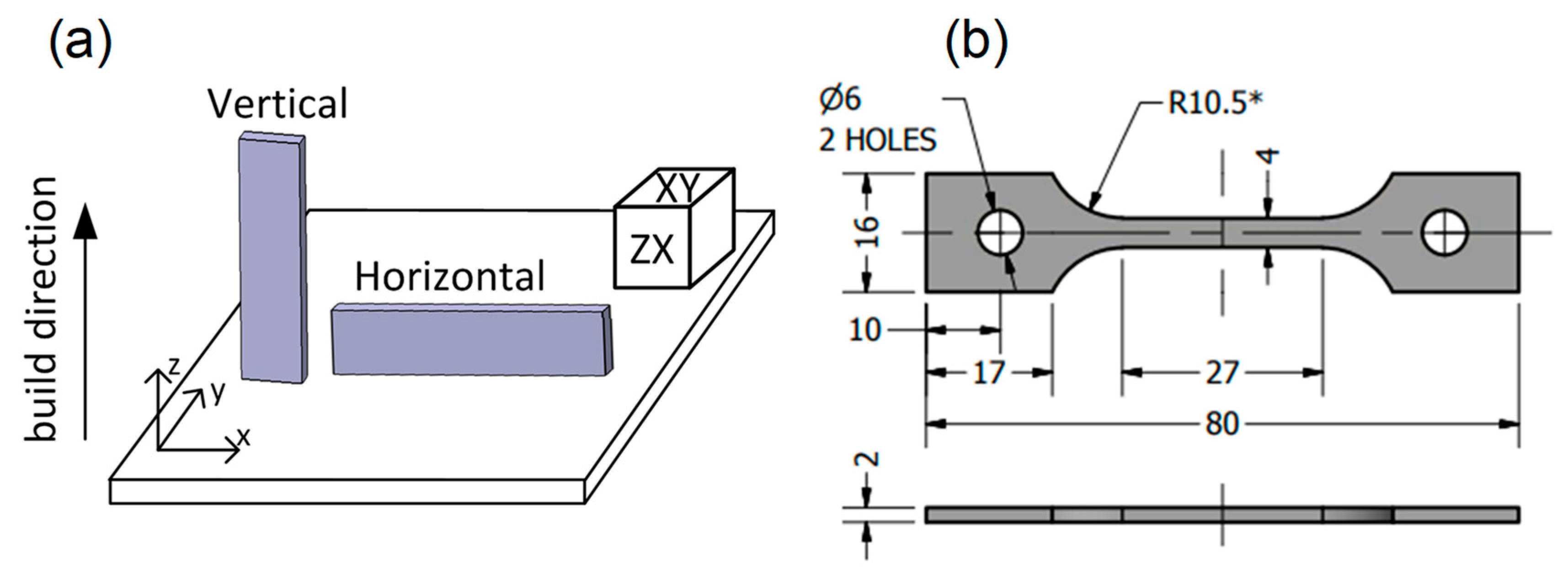
In this study, IN625 powder (EOS GmbH, Munich, Germany) with a chemical composition corresponding to UNS N06625 and ASTM B443 was used. An EOSINT M290 (EOS GmbH, Munich Germany) laser powder bed fusion system equipped with a 400 W ytterbium fiber laser and the EOS IN625_Surface 1.0 Parameter Set (laser power ~300 W, scanning speed ~1000 mm/s, hatching space ~0.1 mm, and layer thickness ~40 µm) was employed to fabricate two types of specimens: 10 × 10 × 10 mm
3 cubic specimens for microstructure evaluation, and 85 × 18 × 3 mm
3 rectangular blanks for tensile testing (
Figure 1a). The blanks were built in two directions relative to the build plate, as defined in
Figure 1a, and have been referred to as vertical or horizontal (parallel or perpendicular to the build direction, respectively) throughout this paper. The chemical compositions of the IN625 powder, the as-built LPBF alloy, and the wrought annealed alloy (reference) are shown in
Table 1.
Following the LPBF, the build plate with cubic and rectangular specimens was subjected to stress relief (SR) annealing at ~900 °C for 1 h (EOS recommendations), followed by forced air cooling (~1.5 °C/s) [
10,
33]. The SR treatments were carried out in a Nabertherm H41/N furnace under argon continuous flow (~15 L/min). Next, all the printed specimens were cut from the platform, using a reciprocated saw, and the rectangular blanks were machined by EDM (electrical discharge machining) to obtain the dumbbell-shaped tensile testing specimens shown in
Figure 1b.
Finally, some SR specimens were reserved for future study, while the others were subjected to either hot isostatic pressing (HIP, Avure Technologies, Quintus QIH-3, Columbus, OH, USA) under pressurized argon atmosphere, followed by furnace cooling (~0.1 °C/s) [
34,
35,
36]; or high temperature solution treatment (ST) for 1 h in an open-air furnace (Pyradia, Longueuil, QC, Canada), followed by air cooling (~0.5 °C/s) (
Figure 2). Both the HIP and ST post-treatments were expected to homogenize the as-built LPBF microstructure and decrease the anisotropy of the IN625 alloy’s mechanical properties. Since HIP is time- and resource-consuming, and can result in undesirable grain growth [
16], ST is seen as its economic and technologically sound alternative.
For this study, it was decided to carry out both treatments at the same temperature in the 1100–1150 °C range. This decision can be explained by the fact that HIP at this temperature had already been successfully used to reduce processing-induced porosity, and to homogenize and recrystallize LPBF-built microstructures [
16,
24,
34]. On the other hand, for a high carbon version of IN625 alloy (~0.045 wt. %C), a typical ST temperature is also in the 1100–1150 °C range [
37].
For reference, wrought IN625 alloy annealed at 980 °C (
Table 1), provided by McMaster Corp. and corresponding to ASTM B443 (Grade 1, with a grain size of ~13 µm), was also characterized in the framework of this study. The Grade 1 (fine-grained) alloy was chosen because it possessed higher mechanical characteristics above 600 °C than the solution-treated Grade 2 (coarse-grained) alloy. The temperature- and time-dependent behaviors of the LPBF and wrought IN625 alloys were compared in this study from the perspective of their concurrent industrial use.
Tensile testing with a strain rate of 10−3·s−1 was conducted at 25, 427, 538, 593, 649, 760, and 871 °C (68, 800, 1000, 1100, 1200, 1400, and 1600 °F) using an MTS 810 testing system equipped with an infrared radiant heating furnace. High temperature testing was realized under argon atmosphere at a flow rate of 5–18 L/h. Prior to tensile testing, specimens were heated at a heating rate of 1 °C/s and maintained at the test temperature for 10 min. The temperature was controlled using three K-type thermocouples in contact with the specimen surface and evenly distributed along its gauge length to control the uniformity of the temperature distribution. The strain was calculated using data provided by the LVDT (linear variable differential transducer) of the testing machine. After each treatment and for each testing temperature, the yield strength (YS corresponding to 0.2% offset strain), the ultimate tensile strength (UTS), and the elongation to failure (ε) were determined. For each experimental point, three specimens were tested, and the mean values of YS, UTS, and ε and their confidence ranges at a confidence probability of p = 0.95 were calculated.
Creep tensile testing was conducted at 760 °C (1400 °F) at 0.5, 0.7, and 0.9 of the YS with a loading rate of 10 N·s−1. The testing system, atmosphere, gas flow, and heating rates for the creep testing were identical to those of the elevated temperature tensile testing. Three tests were conducted for each creep condition, and the rupture time (τ), the fracture strain (ε), and the steady or secondary creep rates () were determined.
The fracture morphology and microstructure were analyzed using scanning electron microscopy (SEM, Hitachi TM3030 system and Hitachi SU8230 system equipped with an electron backscatter diffraction (EBSD) unit). The microstructural analysis was performed on the horizontal (XY) and vertical (ZX) reference faces of the cubic specimens (
Figure 1a). All the specimens were polished manually (down to 1 μm grit size), and then using a vibrometer and colloidal silica (0.05 μm grit size). For EBSD analysis, samples were tilted at 70° and scanned at 20 kV, with a step of 1–2 μm.
4. Discussion
Grain size and grain orientation. It was shown that LPBF processing was responsible for the formation of an anisotropic microstructure. The SR specimens contained grains elongated in the build direction with the dominant [001] texture, inherited from the as-built material. The grain length was more than twice the layer thickness, while the average width was about 20 µm. During the ST and HIP treatments, grain growth caused the microstructure to become nearly equiaxed with a random texture. The average grain sizes after the ST and HIP treatments were about 20 and 45 µm, respectively [
16].
Map of the mechanical properties. The mechanical properties obtained at a 10
−3·s
−1 strain rate across a wide range of temperatures are shown in
Figure 10a–c for the SR-, ST-, and HIP-treated LPBF IN625 alloys, respectively. The mechanical properties of the vertical and horizontal SR specimens have been presented here, while the properties of the ST and HIP specimens are limited to those of the vertical specimens. For reference, the mechanical properties of the wrought annealed alloy are also illustrated in
Figure 10d.
Regarding the mechanical properties overall, all specimens exhibited a decrease in the YS and UTS values as the test temperature increased, due to enhanced plastic flow causing tensile deformation at relatively lower stresses (
Figure 5). However, their elongations to failure evolved differently, as discussed further.
Tensile strength characteristics (YS, UTS): The results show that at room temperature, the SR specimens exhibited the highest mechanical strengths (YS and UTS) (
Figure 10a) and their mechanical strength characteristics exceeded those reported in the ASTM F3056-14 standard (min. 275 MPa (YS) and min. 485 MPa (UTS)) and EOS datasheet (min. 414 MPa (YS) and min. 827 MPa (UTS)) for LPBF IN625 alloy. Regarding other studies, the mechanical properties at room temperature of the SR specimens obtained in this study were comparable to those reported in References [
13,
19,
21,
38] for the as-built LPBF IN625 alloy. However, the high mechanical strength of the SR specimens came with a significant orientation dependency in the mechanical characteristics due to a strong microstructure anisotropy, which was inherited from the as-built material [
16]. Thus, a finer microstructure in the build plane resulted in higher YS and UTS values of the horizontal specimens as compared to their vertical counterparts. By contrast, the ST and HIP specimens containing equiaxed grains and a random texture manifested build-orientation-independent behavior, but lower mechanical strength characteristics. The equiaxed grain structure and reduced mechanical strength characteristics after post-treatments performed at temperatures higher than 1100 °C have also been reported in References [
13,
21].
At elevated temperatures of up to 593 °C, the YS and UTS values decreased continuously with increasing temperature for all the tested specimens. The orientation dependency and the high mechanical strength characteristics of the SR specimens were preserved at these temperatures. The YS and UTS values of the ST and HIP specimens were still slightly lower than those of the wrought annealed alloy.
With a further temperature increase to up to 760 °C, a rapid decrease in mechanical strength characteristics was observed for the SR specimens, which was caused by dynamic recrystallization [
24]. As a result, no difference was observed between the YS and UTS values. The ST- and HIP-treated specimens were capable of maintaining their structural strength to up to 760 °C, and their UTS values became comparable to those of the SR specimens. For the ST- and HIP-treated specimens, dynamic recrystallization took place at 871 °C. At this temperature, the YS and UTS values of all the tested specimens were comparable.
Elongation to failure: From RT to intermediate temperatures (538 °C), the elongations to failure increased for all the specimens. However, the peak in elongations was observed at 593 °C for the SR specimens, and at 538 °C for the ST and HIP specimens. Note that for the wrought annealed alloy, the elongation always increased with an increase in testing temperature (
Figure 10d). At higher temperatures, the LPBF alloy manifested a significant reduction in elongation. Such a significant decrease in elongation of the LPBF alloy at 760 °C was accompanied by changes in fracture pattern due to weakening of the grain boundaries at elevated temperatures (ductile/brittle transition) [
24]. Moreover, the intergranular cracking mode led to a significant increase in the orientation dependency for the SR specimens in the 593–871 °C temperature range. The elongated grains oriented along the axis of testing were responsible for higher elongations of the vertical SR specimens as compared to their horizontal counterparts. After the ST and HIP treatments, the grains became equiaxed and their mean size increased, resulting in elongations to failure higher than for the horizontal SR, but lower than for the vertical SR specimens.
The elevated temperature embrittlement observed in this study is a known phenomenon for many Ni-based alloys. The reasons for this behavior are subject to discussion [
22]. In particular, the embrittlement has been attributed to intergranular precipitates, grain boundary shearing or sliding, gas phase embrittlement, dynamic strain aging, grain boundary segregation, and glide plane decohesion [
22]. For IN625 alloy, this phenomenon is mostly associated with precipitates (carbides, M
23C
6 and M
6C, and δ phase) distributed along grain boundaries [
2,
24,
39,
40]. More specifically, according to Reference [
24], cracks preferentially propagate along grain boundaries containing M
6C carbides.
Finally, it should be mentioned that the mechanical behaviors of the ST- and HIP-treated specimens were similar (
Figure 10b,c). While the YS and UTS values of the ST specimens were slightly higher, their elongations were slightly lower than those of the HIP specimens.
High-temperature creep properties. It was found that as well as the tensile properties, the SR-annealed alloy exhibited orientation dependency of its creep behavior: vertically built specimens showed higher lifetimes and lower rupture strains compared to their horizontally built counterparts (
Figure 7 and
Figure 8). Despite the high lifetimes of the vertical SR specimens as compared to the vertical ST and wrought specimens (
Figure 11), the anisotropy in mechanical properties of the SR LPBF IN625 alloy makes its behavior unpredictable. Thus, heat treatment including only stress-relief annealing is not recommended for the practical use of LPBF IN625 alloy.
Regarding the ST-treated LPBF alloy, at the same creep-to-yield stress ratio, the ST specimens exhibited significantly improved creep properties as compared to the reference wrought annealed alloy. However, in the “absolute creep stress-rupture time” diagram (
Figure 11), at first sight, the ST specimens still had an advantage over the wrought annealed alloy, especially at intermediate and low stresses (≤200 MPa). Using the “strain–time” creep curves, the steady creep rates were measured and are collected in
Figure 12. It was clearly observed that the higher the applied stress, the higher the steady creep rate, which led to shorter lifetimes for the SR, ST, and wrought alloys, and a higher fraction of the intergranular fracture areas for the SR and ST alloys. However, it was seen that under the same creep stress of ≥150 MPa, the steady creep rates for the wrought and SR-treated LPBF alloys were higher than that for the ST-treated LPBF alloy.
In general, creep behavior depends strongly on the metallurgical structure, i.e., the grain and particle sizes, the concentration of the alloying elements, and the creep conditions: stress and temperature. All the structure characteristics mentioned will affect the structural stability against vacancies and dislocations mobility, grain boundary diffusion, and, consequently, crack initiation and propagation at high temperatures under creep stresses [
41]. In this study, for example, concentrations of Fe and C in the LPBF alloy were lower than in the wrought alloy. Note that according to the data of Heubner [
42], elevated contents of Fe and C in IN625 negatively affect the creep behavior, especially at high temperatures.
Ni-based superalloys are polycrystalline and multiphase materials, and as such, correlating their properties with structural features is not straightforward. In particular, regarding the grain size influence, some data for IN718 demonstrate that an increase in grain size reduced the total creep rupture time, regardless of whether their grain boundaries are clean or intensively decorated with δ precipitates (67%) [
43]. However, in classic cases, the trend is just the opposite: the coarser the structure, the greater the creep resistance [
41]. A possible explanation for these discrepancies is probably related to the testing methodology: the same stress would create more severe creep conditions for coarse-grained structures with lower strength characteristics (YS, UTS) than for fine-grained structures with higher strength characteristics.
It has also been shown that the greater the density of δ precipitates at IN718 alloy grain boundaries, the shorter the total creep time, but when this density exceeds 45%, the creep time increases rapidly [
43]. It has been suggested that with an increase in the density of precipitates at grain boundaries, the formation of wedge cracks at triple points can be delayed to the stage where creep voids around precipitates situated far from the triple edges are able to grow into unstable cracks. Thus, the beginning of the tertiary stage, characterized by rapid crack propagation, is delayed. Note, however, that in this study, all the creep tests were carried out at the same stresses, and thus, the variations in the mechanical strength of alloys with different precipitation densities were not taken into account.
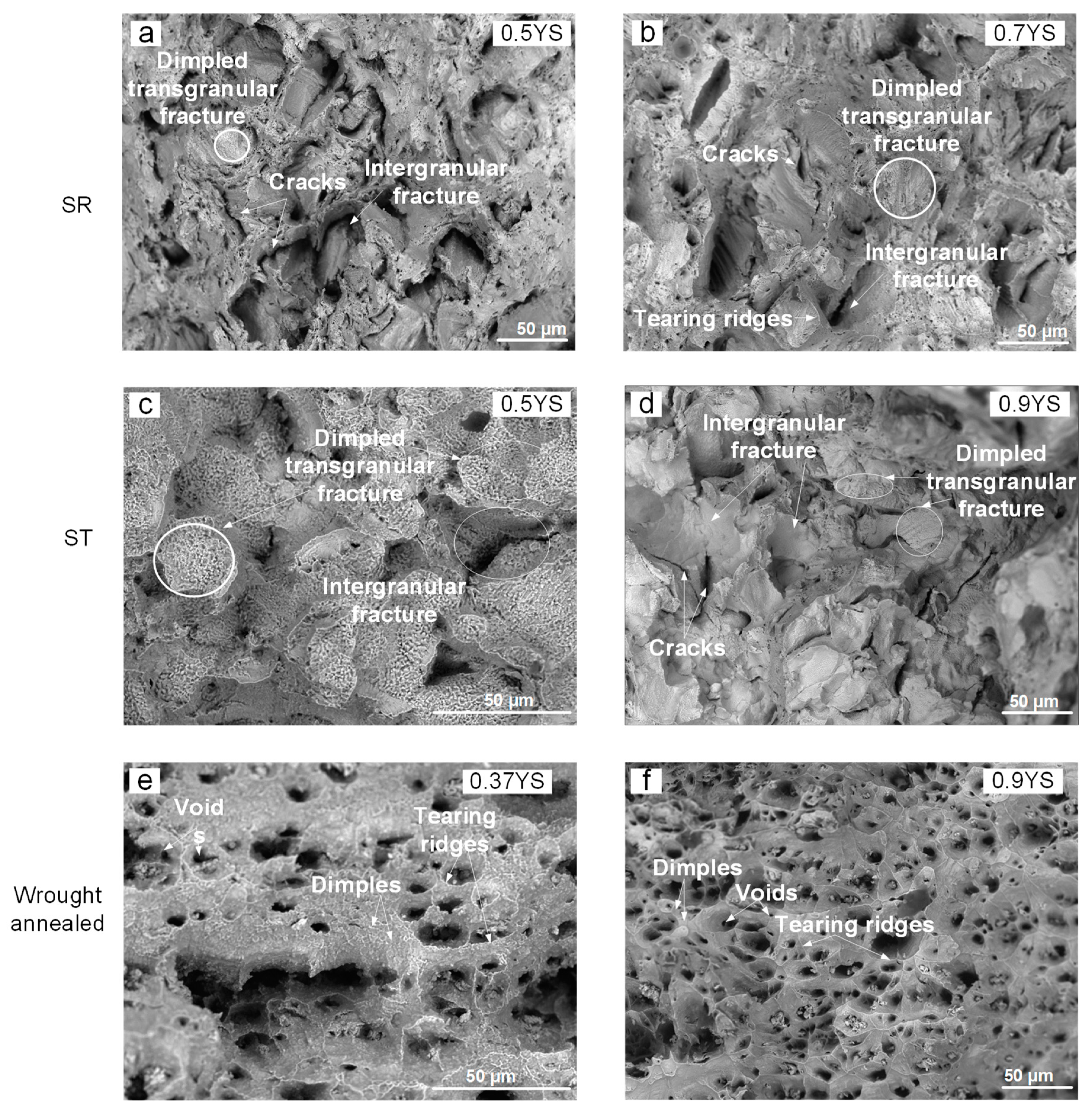
A correlation between the creep rate (
Figure 7) and the fractography (
Figure 9) observations was be noted. For example, the specimens of the wrought annealed alloy accumulated a significant elongation to failure during their final (tertiary) creep stage, which was reflected by a dimpled fracture surface. At the same time, the ST specimens manifested a long, steady creep stage related to grain boundary sliding, void formation, and crack initiation, which was reflected by fast intergranular/transgranular crack propagation to failure.
Since the aim of the present article was mainly to present the tensile and creep properties of LPBF IN625 alloy, the authors will concentrate more efforts on establishing a correlation between the structural features and the functional properties in the next publication. However, to summarize, the SR-treated IN625 alloy contained needle-like δ phase and globular precipitates of M
6C carbides on grain boundaries [
24], whereas the grain structures and phase states of the ST- and HIP-treated alloys were comparable. It has been previously shown that HIP dissolves the δ phase precipitates, forms MC, and homogenizes initially anisotropic SR-structure [
24]. Thus, the presence of a significant quantity (that should be evaluated) of intergranular δ phase precipitates in vertical SR specimens reinforces grain boundaries against the sliding and formation of voids under stresses. After ST, in the case of an equiaxed grain structure with inter- and transgranular carbides, the creep lifetime is less significant, but the ST structure still has advantages over the wrought annealed specimen.
Summary. It was seen that the SR-treated LPBF alloy exhibited the highest anisotropy, i.e., build orientation dependency, and the least predictable mechanical behavior, as compared to its ST- and HIP-treated counterparts. Therefore, the SR alloy is the least safe material for practical use, especially at elevated temperatures. The ST and HIP treatments improved the alloy homogeneity and provided isotropic properties, thus making these alloys more application-safe. The mechanical strength characteristics of the LPBF alloy after the ST and HIP treatments satisfied the ASTM B444 standard requiring high strength in the 25–593 °C (68–1100 °F) temperature range.
Note that while the HIP alloy can be seen as a material with more uniform mechanical characteristics and improved ductility over the ST-treated alloy, this advantage came at the expense of the lower strength characteristics.
Furthermore, at T ≥ 650 °C, special attention must be paid to the time-dependent properties (creep). It was seen that although the LPBF alloy manifested much lower static ductility at these temperatures, it offered significantly longer rupture times under stresses of <200 MPa, as compared to its wrought annealed counterpart (
Figure 13).


