Article

Scale, Material Concentration, Stress Relief and Part Removal Effects on the Dimensional Behaviour of Selected AlSi10Mg Components Manufactured by Laser Powder Bed Fusion

Department of Mechanical Engineering, École de technologie supérieure (ÉTS), Montreal, QC H3C 1K3, Canada
*
Author to whom correspondence should be addressed.
J. Manuf. Mater. Process. 2019, 3(2), 49; https://doi.org/10.3390/jmmp3020049
Submission received: 2 May 2019 / Revised: 27 May 2019 / Accepted: 13 June 2019 / Published: 18 June 2019
(This article belongs to the Special Issue Recent Development in Metal Additive Manufacturing)

Abstract

:
Laser Powder Bed Fusion (LPBF) is a predominant Additive Manufacturing (AM) process. While metallic LPBF is gaining popularity, one of the barriers facing its wider industrial use is the current relatively limited knowledge with respect to its dimensional and geometrical performance, as well as the inability to predict it. This paper presents an experimental investigation of the geometrical and dimensional deviations of selected LPBF-manufactured components according to the ASME Y14.5 (2009) standard. In this study, two types of axisymmetric parts (cylinder and cylindrical pyramid) were designed with three different levels of material concentration, and replicated at three different scales for a total of 18 test artifacts. These parts were manufactured from AlSi10Mg powder using an EOSINT M280 printer, subjected to stress relief annealing at 300 °C for two hours, removed from the platform and finished by micro shot peening. A complete statistical analysis was carried out on the artifacts before and after each post-processing step. The results of this investigation allowed for the quantification of the intra- (same part) and inter- (different parts) scale effects, as well as of the material concentration, stress relief, part removal and micro shot peening effects on the overall three-dimensional (3D) profile deviations and on the dimensional deviations of some selected features (e.g., diameter, thickness). For example, cylindrical pyramid parts showed the following average deviations of their outside diameters: a −63 µm shrinkage of the as-built part diameter as compared to its computer-assisted design (CAD) value, a +20 µm expansion after stress relief annealing as compared to the precedent step, a −18 µm shrinkage after part removal and, finally, a −50 µm shrinkage after micro shot peening.

1. Introduction

Additive Manufacturing (AM) is the term used for technologies that produce three-dimensional (3D) functional parts from nominal computer-assisted design (CAD) files using typically layer-by-layer material deposition techniques. These technologies do not require conventional tooling to build components since the shape is produced by adding, rather than removing or deforming, material. The material can be polymer, metal, composite, ceramic, concrete or even human cells. Many AM processes have been developed and are commercially available, including Stereolithography (STL), Fused Deposition Modelling (FDM), Three-Dimensional Printing (3DP), Powder Bed Fusion (PBF), Direct Metal Deposition (DMD) and Sheet Lamination (SL). The PBF technologies include two variants depending on the nature of the heat source: the Electron Beam Powder Bed Fusion (EBPBF) and the Laser Powder Bed Fusion (LPBF). AM standard terminologies are framed by ISO/ASTM 52900:2015 [1] and their general principles are described in ISO/ASTM52901-16 [2].
LPBF is one of the most used processes for metallic AM, which builds three-dimensional parts directly from metal powder. In a chamber filled with inert gas, a high-power laser beam selectively scans a thin layer of metallic powder, resulting in local melting. Dimensional accuracy prediction and control remains a major concern when it comes to the industrial adoption of this technology.
To investigate the process feasibility and transpose the information collected into the process performance, many researchers have proposed AM test artifacts that are meant to quantify the capabilities, limitations and accuracy of the machine and the process, and to diagnose specific processing defects [3]. Richter and Jacobs [4] suggested that the standard test artifact should be large enough to test the performance of the machine near the edges of the platform as well as near the center, have a substantial number of small, medium and large features and have both holes and bosses to aid in verifying beam width compensation. In addition, it should not take too long to build, nor consume a large quantity of material, and should be easy to measure. Byun et al. [5] added that the test part should also have evaluation features to assess whether or not it is possible to manufacture fine features under the specific AM process. Accordingly, these fine features should be set up in all axes, and their size should be varied while considering the improvement in the process mechanisms and resolutions of AM machines. Kruth et al. [6] stated that such artifacts should not only be used to analyse the process limitations, but also to optimise the process iteratively. Some other authors have made notable advances in the field of AM artifact design [7,8,9,10,11,12,13,14,15,16,17].
Globally, to date, researchers have focused more on the feasibility issues and less on the statistical effects of processing and post-processing operations on final part deviations. Knowing that geometrical deviations strongly impact the service performance of structural parts, this lack of reliable metrological information hinders widespread industrial adoption of AM technologies.
To fill this gap, different authors have studied and tried to predict dimensional and geometrical deviations of AM parts with varying levels of success. For example, Singh et al. [18] quantified the effects of laser power, scan spacing, powder bed temperature, hatch length and scan count on the geometrical deviations of Selective Laser Sintering (SLS) polyamide parts. Next, Huang et al. [19] investigated the compensation of the geometrical deviations on SLA SI500 (resin) parts. They presented a statistical predictive compensation approach to predict and improve the quality of cylindrical and prismatic parts. However, only the XY plane deformation errors were taken into account, while the Z coordinate was ignored. Moreover, after the compensation, the parts still presented the same systematic deformation pattern as before, and only the average profile deviation was improved, but not entirely corrected.
Similar works can be found on metal AM. For example, Zongo et al. [20] carried out an intra- and inter-repeatability study of profile deviations, and the results of the investigation demonstrated that the LPBF performance for geometrical variations of 147 identical AlSi10Mg parts falls within a range of 230 µm at a 99.73% confidence level. Using the same process, powder and stress relief annealing heat treatment, Calignano et al. [21] studied the dimensional limits of geometries with sharp edges. They quantified the effect of STL file tolerances on the printed part deviations. Next, Van Bael et al. [22] investigated the geometrical controllability of LPBF-built Ti6Al4V porous structures by means of a feedback loop between the design and the printed part deviations. After two iterations, the average pore size mismatch was decreased from 45 to 5%. Li et al. [23] investigated the effect of micro-vibrations on the final part’s porosity and mechanical properties. They demonstrated that 969 Hz vibrations can decrease the density of AlSi10Mg parts printed using a KUKA six-axis robot from 100 to 99.1%. Next, Liu et al. [24] demonstrated that if each layer is scanned twice, the part density increases by 0.1%, and if it is scanned three times, the density is increased further by 0.3%. It is evident that these modifications in processing sequence must have affected not only the part density but also its geometry; this last aspect was not considered in these works.
Notwithstanding the above, the number of metrological studies of AM processes is still limited. This paper isolates and quantifies the intra- (same part) and inter- (different parts) scale effect, and the material concentration, stress relief (SR), part removal (PR) and micro shot peening effects on the 3D profile deviations of selected simplified test components. The results of these analyses can serve as an accessible experimental database for the validation of numerical models intended to predict the geometrical and dimensional deviations of LPBF parts. The ultimate goal of this study is to improve the design support for the LPBF technologies.
The paper is organised as follows. Section 2 describes the part used and the experiment protocol followed. The results are presented and discussed in Section 3. Finally, a summary is provided and future work is described in Section 4.

2. Methodology

To isolate, test and quantify the effects influencing LPBF part geometrical deviations, two test artifacts were designed. The first, referred to as the Shape A artifact, is a cylindrical part containing a coaxial cylindrical pocket displaying a diameter of half of the full cylinder (Figure 1). This artifact was manufactured in 12 versions. The variables are the pocket depth (from P1 being one-fourth depth to P4 completely hollow) and the part size (from S1 small to S3 large), as described in Figure 1. The Shape B artifact is a four-step cylindrical pyramid. This artifact was manufactured in six versions. The variables are the absence or presence of a coaxial pocket with a diameter of half of the smallest cylinder (P0 means no pocket and P4 stands for completely hollow) and the part’s relative scale S1–S3, as described in Figure 1.
The pocket depth variant (P) allows for the isolation and quantification of the impact of the material concentration on the part deviations, while the scale variant (S) allows for the isolation and quantification of the impact of the scale effect on the part deviations.
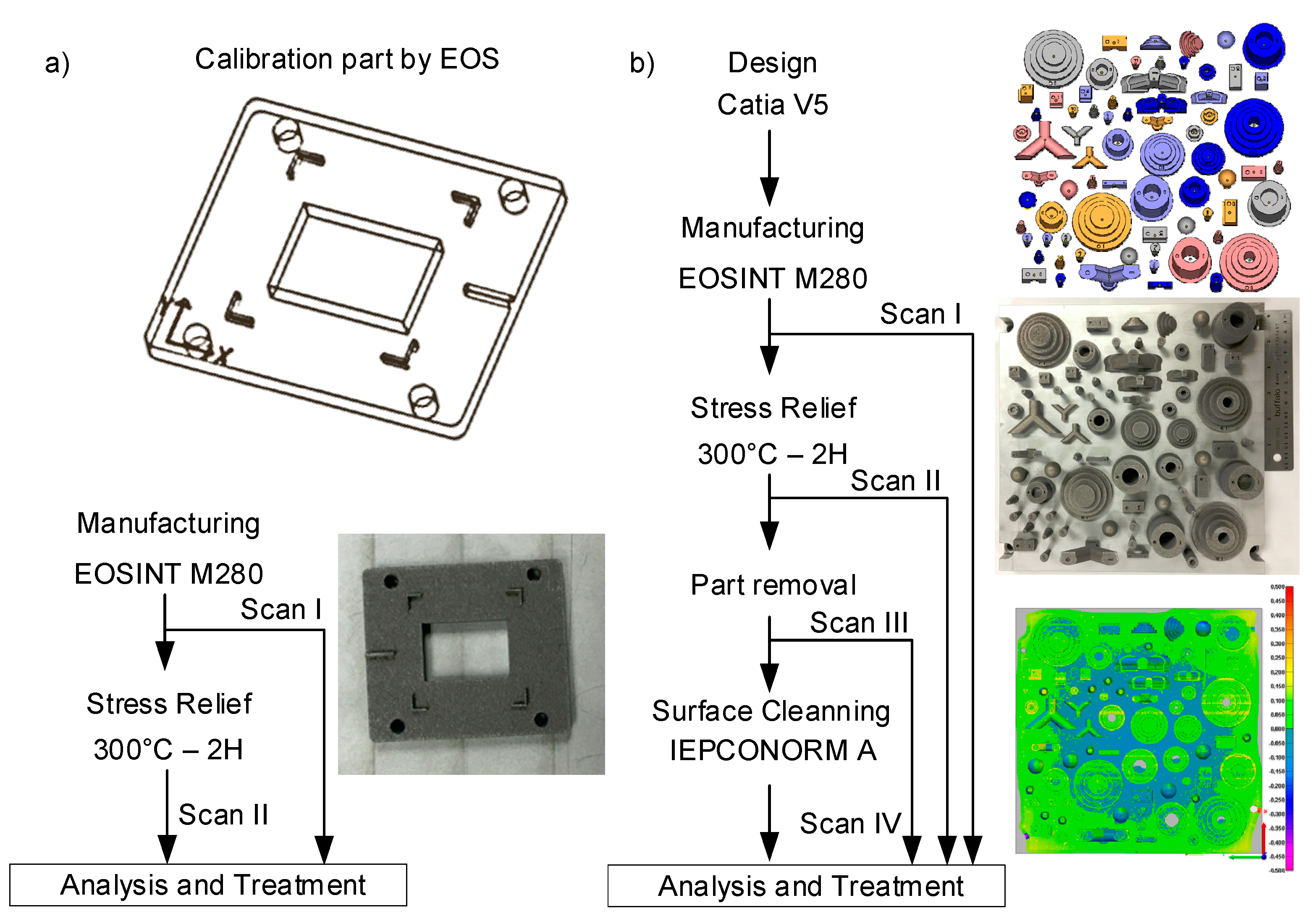
All of the parts of this study were printed using an EOSINT M280 system (Electro Optical System, Germany), and AlSi10Mg powder with the AlSi10Mg_Speed 103 process parameter set (laser power 370 W, scanning speed 1300 mm/s, hatching space 0.19 mm and layer thickness 30 µm). The used AlSi10Mg powder has a particle size distribution of D10 = 12.8 µm, D50 = 27.7 µm and D90 = 51.3 µm; the tap density 1.358 g/cm3; the apparent density 1.081 g/cm3 and the Hausner ratio 1.256 [25]. Prior to printing the test artifacts, a beam offset calibration was performed. To this end, the calibration part was printed and inspected (Figure 2a). The part was then scanned by means of a Renishaw PH10 probe mounted on a Mitutoyo Coordinate Measuring Machine (CMM) (4 µm accuracy at a 95% confidence level). Data were collected on the as-built part and after stress relief of 300 °C for two hours. The results of the as-built part’s inspection were used to assess the quality of the beam offset correction protocol suggested by the LPBF system manufacturer.
After the beam offset correction, eighteen (18) AlSi10Mg artifacts were printed using the same LPBF system, material and parameters for the calibration part (Figure 2b). The point cloud of the parts printed was obtained by means of a Metris LC50 laser scan mounted on a CMM ( ± 7 µm accuracy at a 95% confidence level) (Figure 2). Before each scan, the devices were calibrated using a master sphere and data collection was performed under multiple angles to maximize the information collection on inner surfaces. A real-time visualisation was possible with the Focus Inspector, a specialised software application. A thin layer of talcum powder was used to reduce part surface reflection. As a result, the potential point cloud density was increased to ensure the best measurements. The point clouds were then assembled from different angles and cleaned. Following a first Geometrical Deviations Extraction (GDE), a second GDE was carried out after stress relief annealing at 300 °C for two hours, as recommended by the LPBF system manufacturer. The heat treatment was conducted under an argon atmosphere followed by air-forced cooling down to room temperature. Next, a third GDE was carried out after the parts were removed from the plate using a 2°mm thick saw on a horizontal setup. Finally, as suggested by the LBPF system manufacturer, micro shot peening was then applied using an IEPCO MICRO 750 S system with the IEPCONORM-A agent (0.2–0.4 mm grain size of crushed corncob), applied with a 3 bar pressure at the perpendicular angle to the specimen surface, at a 3–5 cm distance, before the fourth and final GDE. The Gaussian best-fit technique and data alignment were performed on the GDEs using PolyWorks® v.16 (Innovmetric Metrological Software). The data were then loaded into Matlab® 2017b (MathWorks), using a code to extract the deviation at each point. Minitab® v.17 (statistical software by Minitab Inc.) was used for the graphic and statistical studies.
To sum up, the calibration analysis (Analysis A) and three types of deviation analyses were performed based on the ASME Y14.5 (2009) tolerancing standard: The scale effect analysis (Analysis B), the part material concentration effect analysis (Analysis C) and the post-processing effect analysis (Analysis D). Each of the deviation analyses was carried out using Shapes A and B artifacts.

2.1. Analysis A—Calibration Part

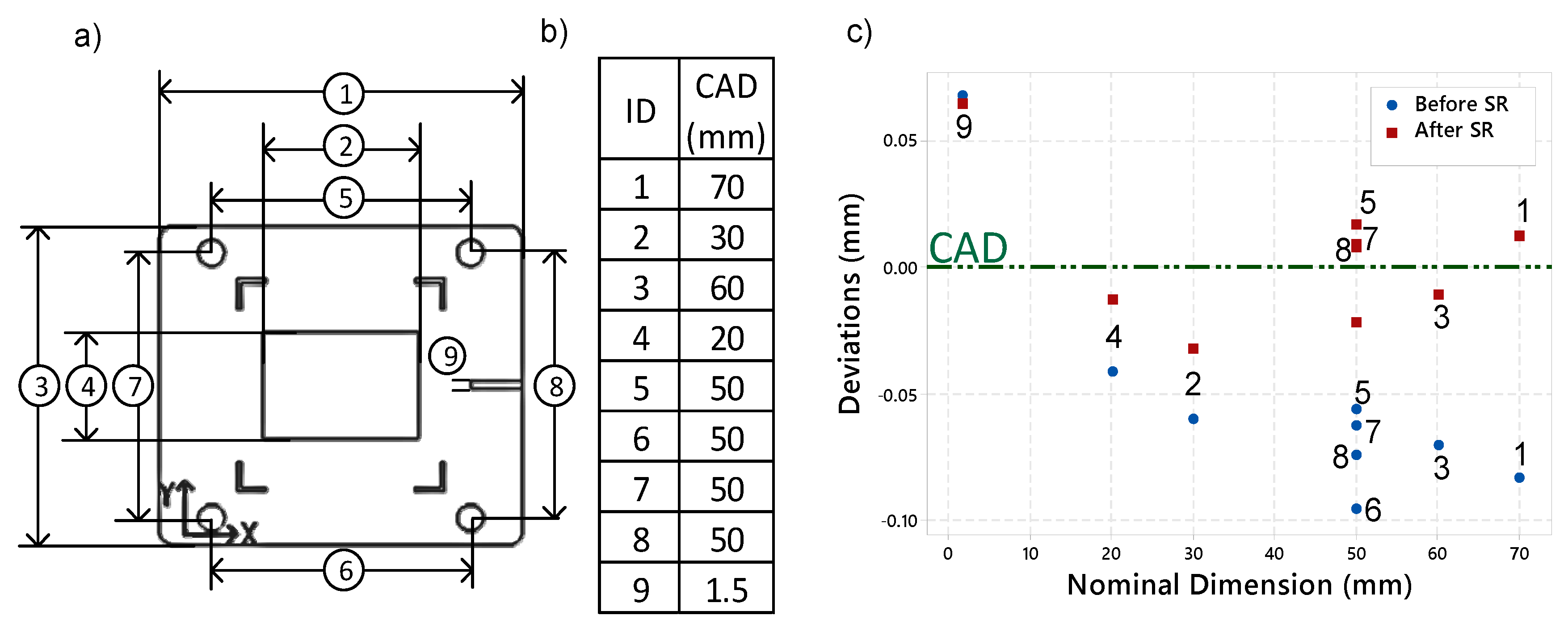
The calibration part inspection was conducted according to the plan provided by EOS. The plan specifies which feature needs to be inspected (see Figure 4a), and how to use the provided Excel sheet to calculate the beam offset, using the results of such an inspection. This analysis was carried out using the part inspection results. The correlation between the feature inspected nominal size and the stress relief effect was investigated.

2.2. Analysis B—Scale Effect

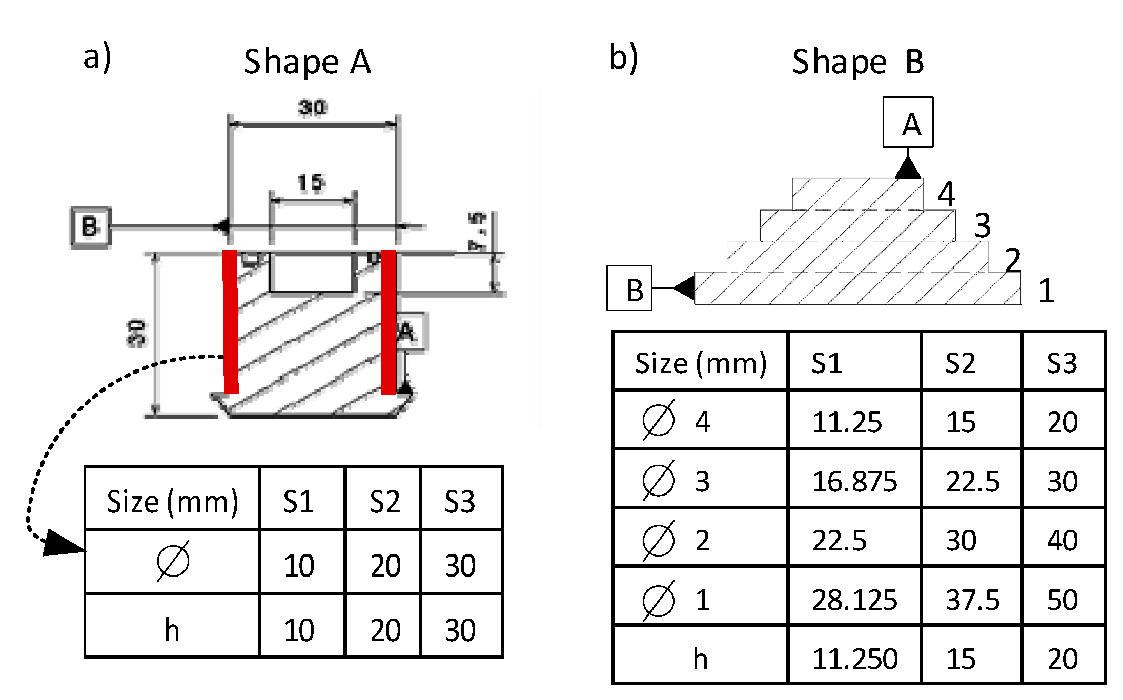
The scale effect analysis was carried out using Shapes A and B. First, an intra-part scale effect (scale effect on different features of the same printed part) was carried out using four cylindrical features of the Shape B artifacts presented in Figure 3b. The framed symbols A and B on the shapes represent the features used for the datum alignment.
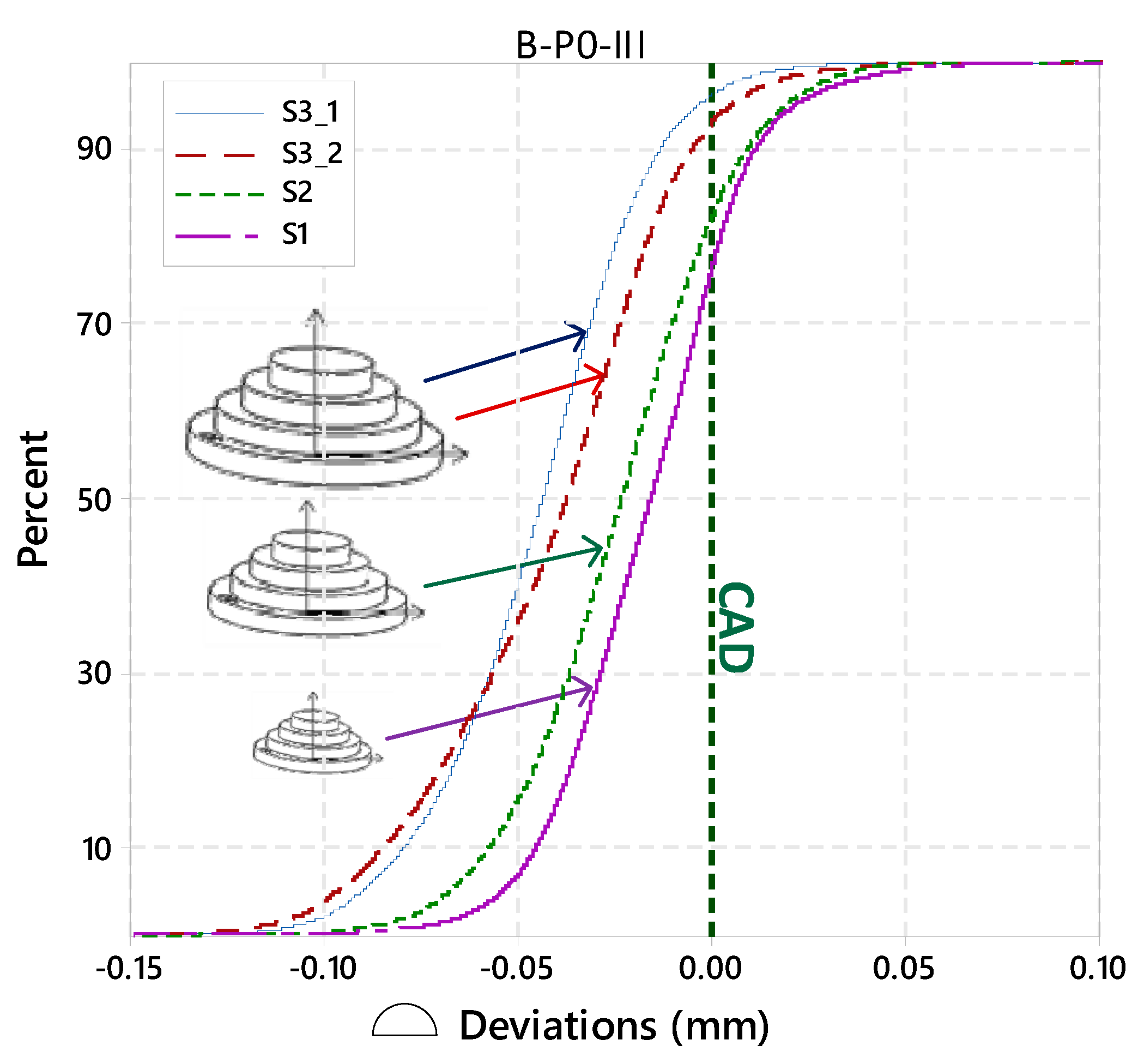
An inter-part scale effect study (comparing the same shape with different part sizes) was carried out using Shapes A and B. Regarding the Shape A artifact, the as-built external diameter deviations were extracted and compared for three different sizes, S1, S2 and S3 (Figure 3a). For the Shape B artifact, the 3D profile deviation nonparametric cumulative distribution functions (CDFs) of all the parts at S1 and S2, as well as of two parts with no pocket (P0) at S3, were used for this study (Figure 3b).

2.3. Analysis C—Material Concentration Effect

In topology optimisation, the material concentration or “pseudo-density” factor describes the layout of the material in a part within a given design space [22]. In this study, the material concentration effect was studied by means of the pockets variant (P0–P4) (Figure 1). To this end, the A-S3-P0 and A-S3-P4 artifacts were printed twice on the plate to confirm the material concentration effect on each of the two parts with different pocket depths. Comparisons were made between parts with the same global shapes and sizes, but pocketed at different depths. Regarding the Shape A artifact, the material concentration effect was studied using the 3D profile deviation of artifacts having four different pockets depths (P1–P4). The results are presented at each post-processing step (PPS). The parts used are at their biggest scale (S3). With the Shape B artifact, the part material concentration effect was studied using the 3D profile deviations of two P0 and P4 pockets depths, with each variation being printed twice. The mean 3D profile deviation is presented at each PPS. The parts used are at their biggest scale (S3).

2.4. Analysis D—Post-Processing Effect

The post-processing effect was studied by observing overall 3D profile deviations and specific feature evolution before (as-built (I)) and after each post-processing step (PPS): stress relief (II), part removal (III), and micro shot peening (IV). The analysis was carried out using Shapes A and B. Regarding the Shape A artifact, the overall 3D profile deviation mean values, before and after stress relief, and the deviation of the external diameter at each PPS were extracted and are presented. The nominal values are specified in Figure 3a. For the Shape B artifact, the overall 3D profile deviation mean values of four parts at S3 were determined. Furthermore, the diameter deviations of four cylinders of the pyramidal shape (Figure 3b) were extracted on each Shape B artifact, at each PPS.
General note: By definition, the deviation is the difference between the nominal value (as defined in the CAD file) and the experimental value extracted from the measurements. Positive deviation means that the measured value is greater than the nominal in the Maximum Material Condition (MMC) direction. Negative deviation means that the measured value is smaller than the nominal in the Least Material Condition (LMC) direction, as in ASME Y14.5.1 [23]. The interval bars presented on the graphics are the measurement system uncertainty at a 95% confidence level.

3. Results and Discussions

The geometrical and dimensional (GD&T) analysis is based on the ASME Y14.5 (2009) standard and provides the following information: (A) the calibration part deviations behaviour before and after the stress relief, (B_1) the intra-parts and (B_2) inter-parts scale effects on the Shapes A and B artifacts (18 parts), (C) the part material concentration effect and (D) the post-processing steps effect. This section displays some analytical graphs (Refer to Appendix B for numerical values).

3.1. Analysis A—Calibration Part Inspection

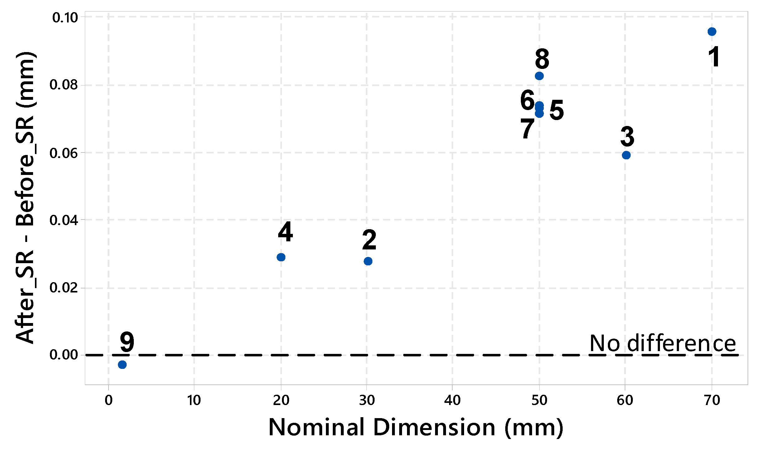
The calibration part inspection results are presented in Figure 4 and Figure 5. Figure 4 presents the deviations before the stress relief (blue) and after the stress relief (red). The numbers next to each point refer to the inspection map (Figure 4a). The measurement system used has an accuracy of 2 µm at the 95% level. Figure 5 presents the difference between the same measurements before and after the stress relief depending on the inspected nominal dimension (after SR - before SR). On the vertical axe, zero value means no differences in the inspected feature before and after SR. Positive values mean there was an SR-induced expansion of the inspected feature, while negative values mean an SR-induced shrinkage of the inspected feature.
We can observe in Figure 4 that, after the stress relief, the distances measured on the calibration part are globally closer to the CAD than before it. This can be attributed to the reduction of internal stresses and, therefore, part distortions after this treatment.
In addition, the difference between the before and after stress-relief states seems to be proportional to the feature size (Figure 5). The distances 1, 3, 5, 6, 7, and 8 have a nominal value varying from 70 to 50 mm. The stress relief expanded them to an average of +60 µm in terms of feature expansion. The distances 4 and 2 have a nominal distance of 20 and 30 mm, respectively. The stress relief expanded them to an average of +25 µm. The distance 9 has a nominal value of 1.5 mm. The stress relief shrinked it by −3 µm.

3.2. Analysis B_1—Intra-Part Scale Effect

The intra-part scale effect is the scale effect observed in features with different scales, inspected on the same part. Given that the Shape A artifact does not present features eligible for this analysis, the intra-part scale effect is only quantified and observed using the Shape B artifact.

Shape B Artifact

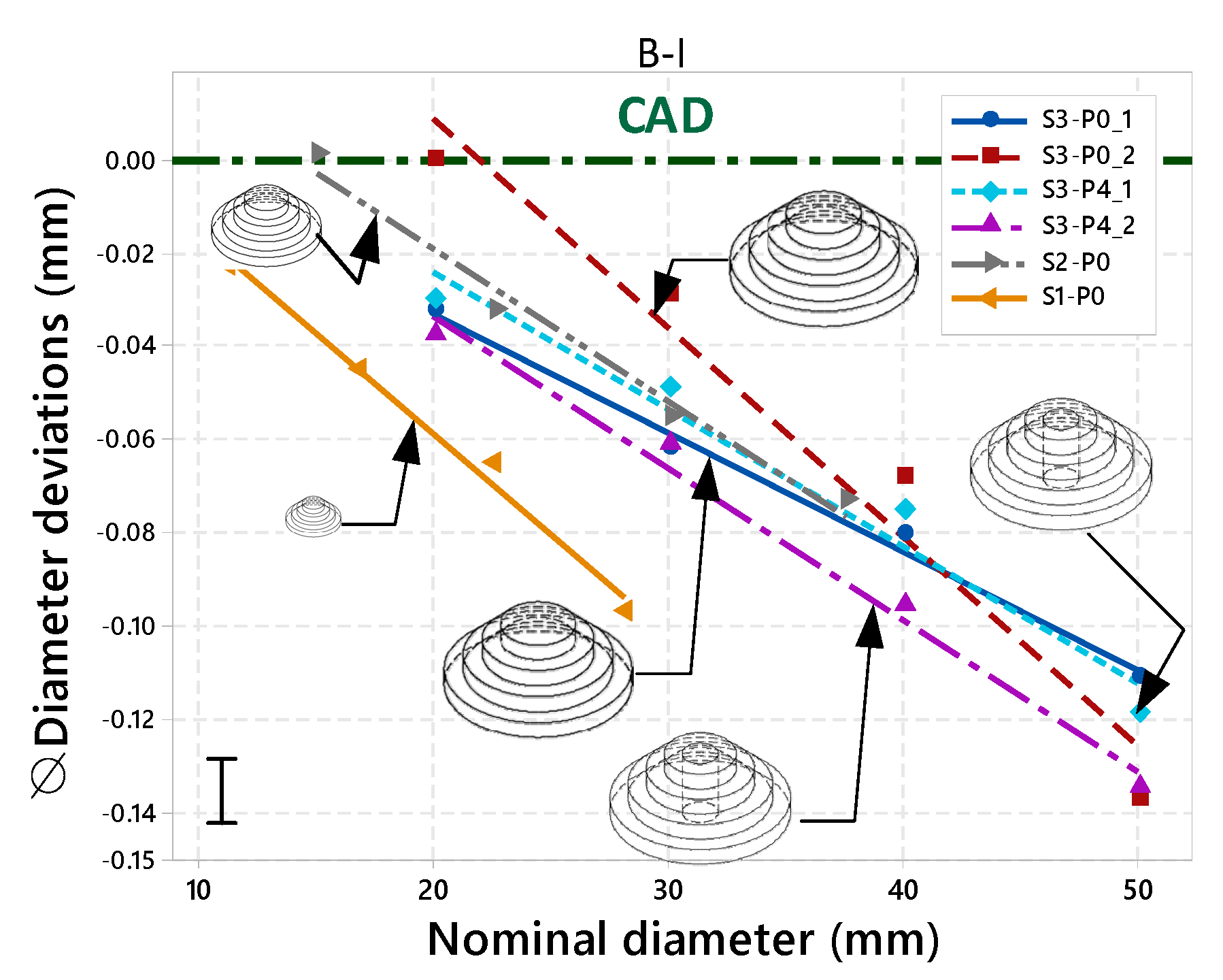
Figure 6 presents the diameter deviations at each of the four steps of the pyramidal shape. Each color represents the four diameters of the same part. Each line was fitted with the deviations of the four diameters of the same part. The measurements presented here were carried out in the as-built state (I). The figure highlights the intra-part scale effect, which is the repartition of the deviations of the same part, depending on the nominal size of the inspected feature.
This study reveals a scale effect on different features of the same part. Each of the six parts of Shape B reveals an intra-part scale effect (Figure 6). The amplitude of this intra-part scale effect seems to be correlated to its feature nominal intra size amplitude, which is the difference between the maximum and minimum sizes of the features of the same part. The four S1 parts have a feature nominal intra size amplitude of 30 mm and an intra-part scale amplitude of 97–137 µm. The S2 and S3 parts have a feature nominal intra size amplitude of 22.5 and 17.1 mm, respectively, and an intra-part scale amplitude of 74 µm for both parts. Collecting more data is needed to confirm this relationship.

3.3. Analysis B_2—Inter-Part Scale Effect

3.3.1. Shape A Artifact

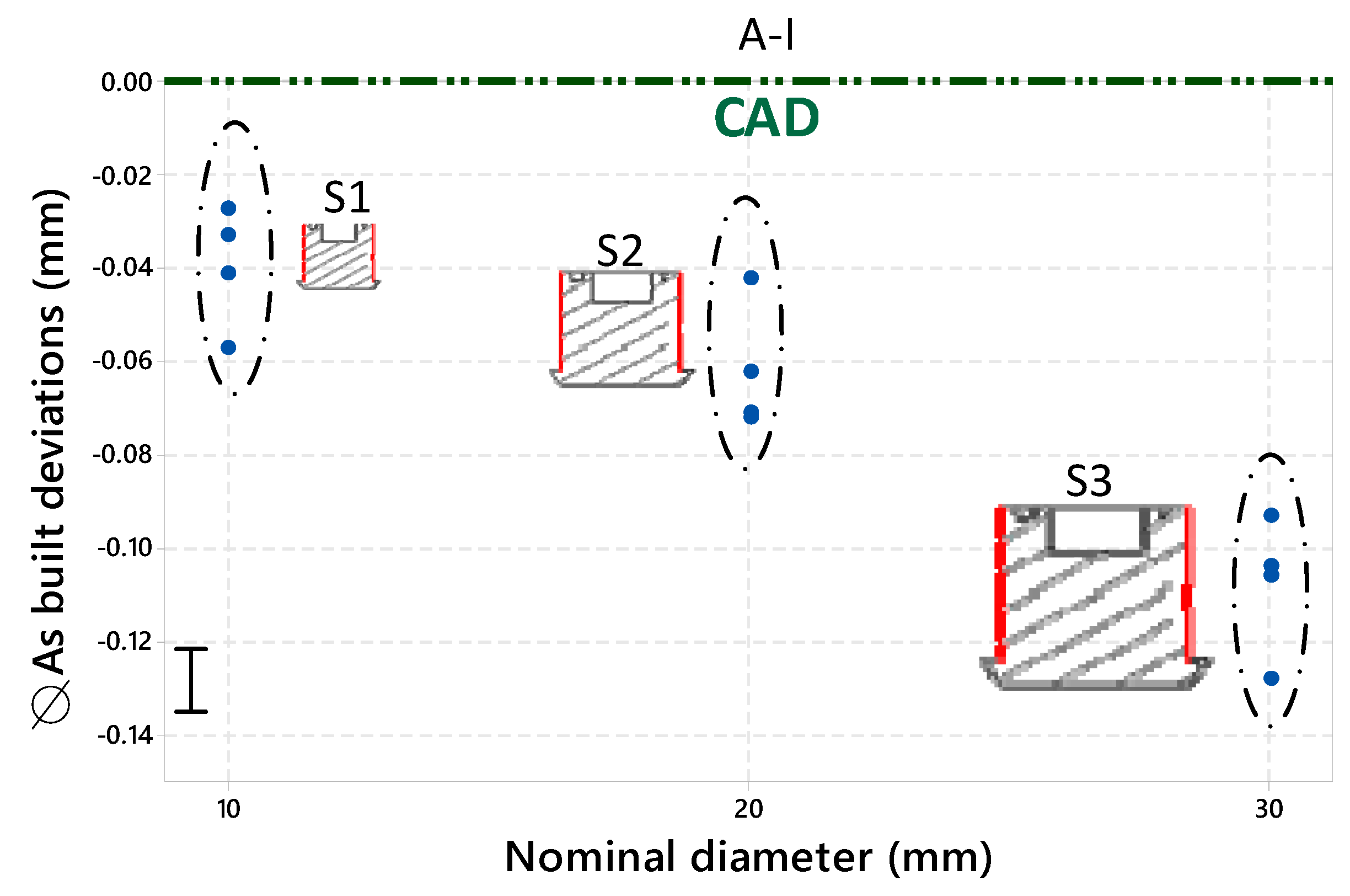
Figure 7 presents the external diameter deviations of 12 Shape A artifacts. Each column presents the deviations of the four parts having the same scale.
The external diameter study of the 12 Shape A artifacts reveals and allows us to quantify an inter-part scale effect with a mean deviation of −39 µm shrinkage (−0.39%) on the (P1 to P4) S1 parts, −61 µm shrinkage (−0.3%) on the S2 parts and −107 µm shrinkage (−0.35%) on the S3 parts. The deviations clearly show a scale effect with a relative shrinkage that is more or less stable for the 12 parts.

3.3.2. Shape B Artifact

Figure 8 presents the 3D profile deviation nonparametric cumulative distribution function of the parts with no pocket (P0) after the part removal (III). We can observe the scale effect between the four parts with three different scales.
The nonparametric cumulative distribution function of the Shape B artifact deviation shows, and allows us to quantify, an inter-parts scale effect. The part B-P0-II-S3_1 (blue) 3D profile mean deviation is −44 µm. The B-P0-II-S3_2 (red) mean deviation is −41 µm. The B-P0-II-S2 (green) mean deviation is −23 µm. The B-P0-II-S1 (purple) mean deviation is −16 µm.

3.4. Analysis C—Part Material Concentration Effect

Shape A Artifact

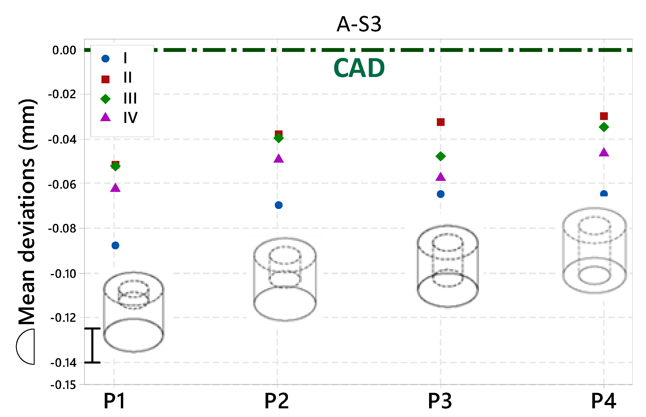
The part material concentration effect was tested using the differences in the deviations of the part having the same shape and scale, with some pockets at different depths. Figure 9 presents the 3D profile mean deviations of the parts having the same shape (A) and scale (S3), with different pocket depths P1 to P4. This figure highlights the material repartition effect on the profile deviations at each PPS.
The 3D profile mean deviation study of the four Shape A and Scale 3 artifacts seems to reveal a correlation between the part material concentration and the deviations. For the same given size, there appear to be less deviations in parts with less material concentration (manifested here by a deeper pocket) than in parts with the same shape, with the exception of a shallower pocket, and, thereby, more material concentration. Collecting more data is needed to confirm this relationship. The same effect was observed with the Shape B artifact. The analysis is in Appendix A.

3.5. Analysis D—Post-Processing Effects

3.5.1. Shape A Artifact

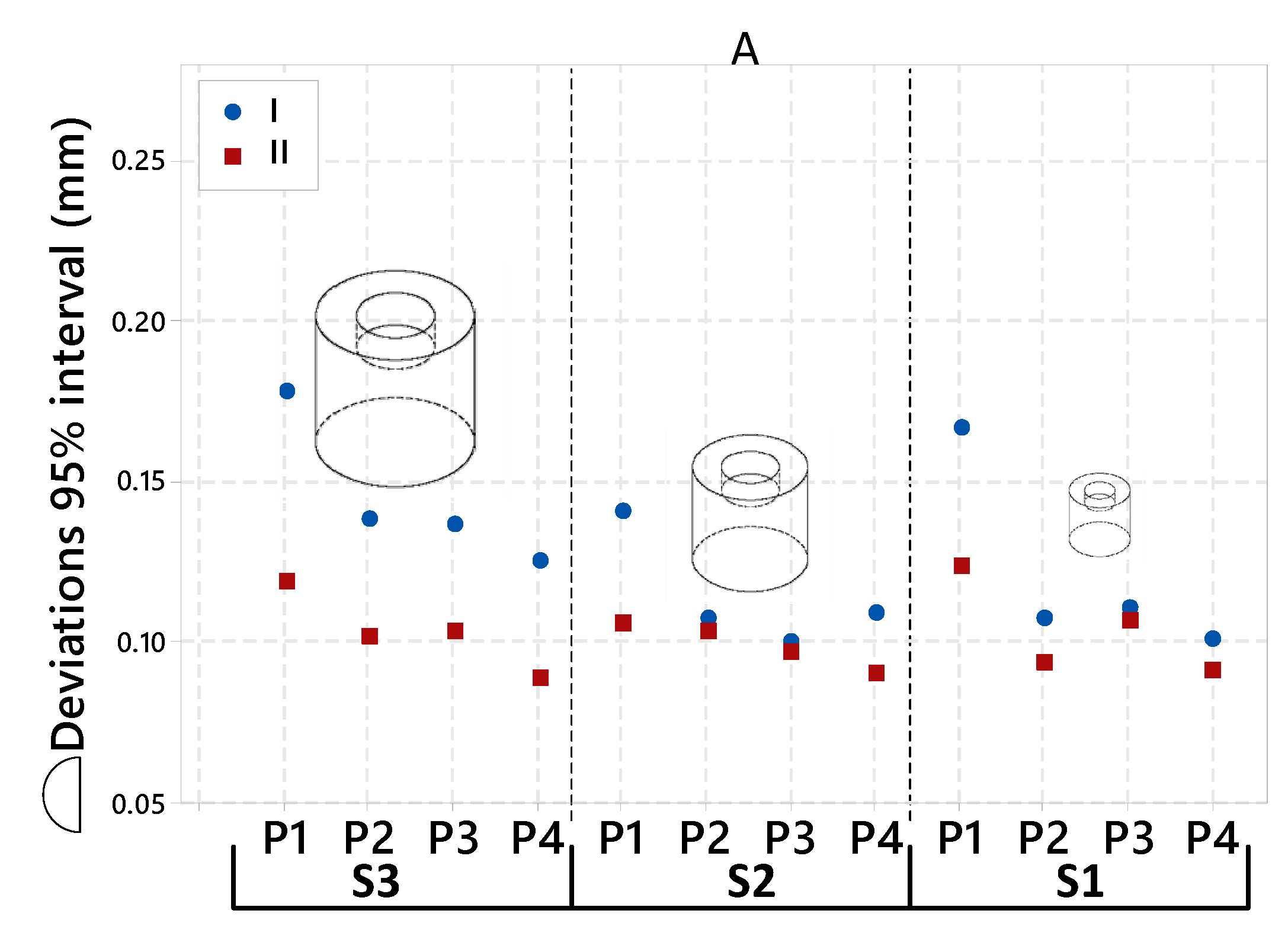
Figure 10 presents the overall 3D profile deviation 95% interval of the 12 Shape A artifacts before (I) and after the stress relief (II).
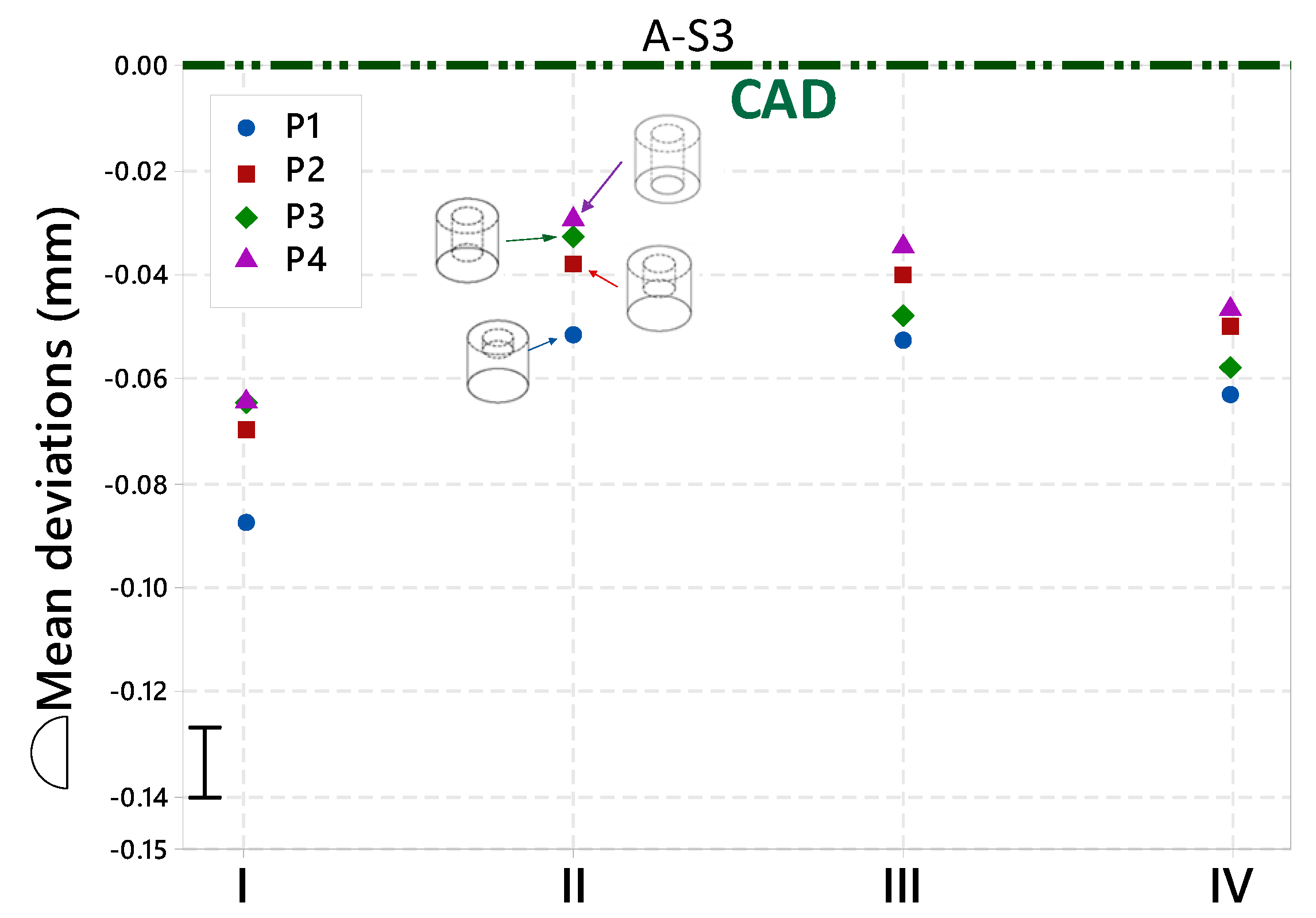
Figure 11 presents the 3D profile deviation mean value of four Shape A artifacts, only at S3, for the four different pocket depths P1–P4, at each PPS. This graph highlights the PPS effects on the profile deviations.
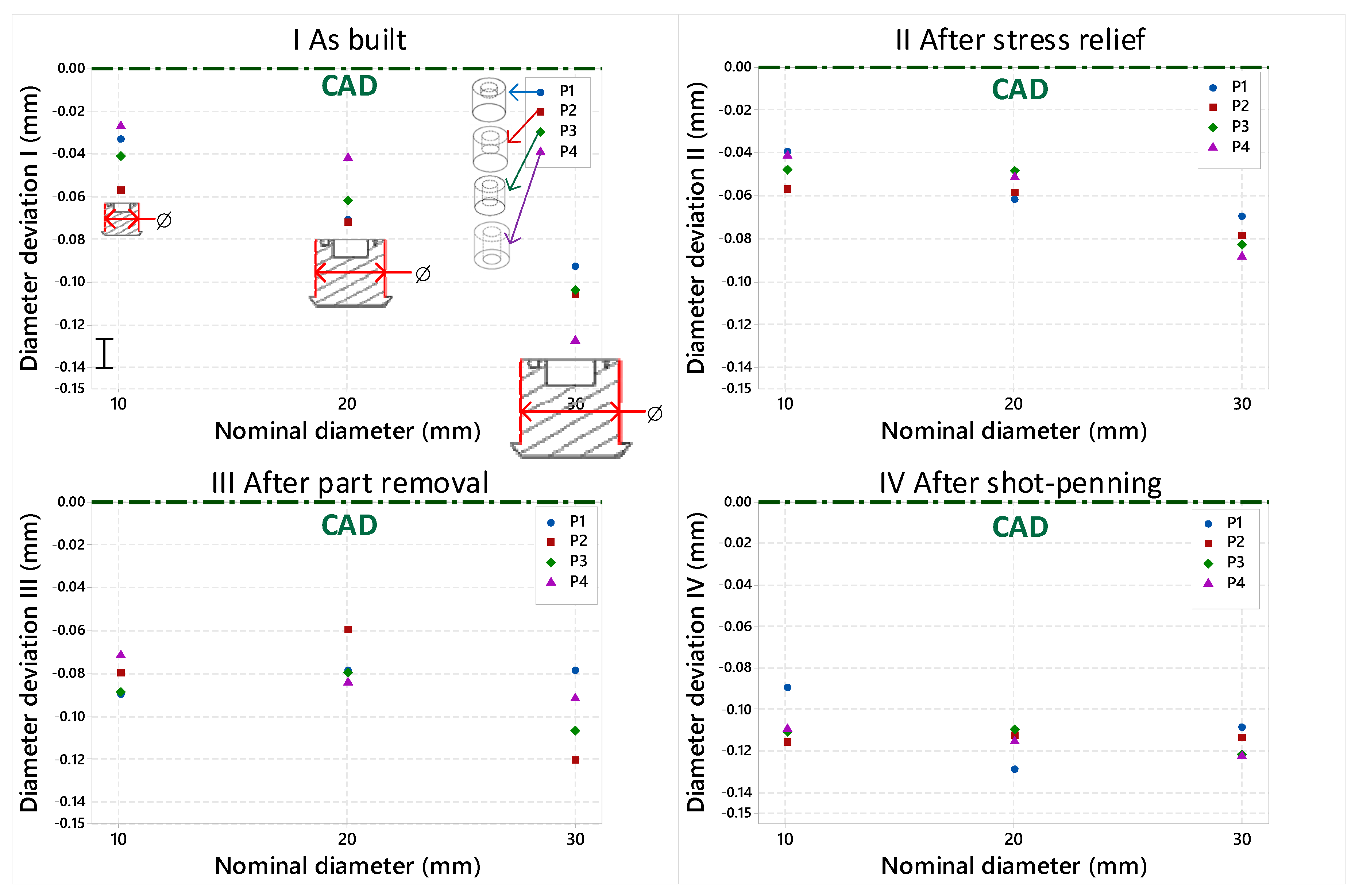
Figure 12 presents the results of the extraction of the external diameter of the Shape A artifact at each PPS. Each graph shows the deviations at one PPS. Each column corresponds to one scale, and each colour, to one pocket depth. The numerical values are available in Table A2.
The stress relief effect can be observed in the overall 3D profile deviation 95% interval. By releasing the residual stresses and preventing part distortions, this PPS positively affects the overall 3D profile deviations by slimming its non-parametric distribution function at a 95% interval (Figure 10).
Figure 11 reveals the PPS effects on the overall 3D profile deviations for the Shape A artifact, only at S3, for the four pockets depths P1–P4. We can observe that the part deviations in the as-built state (I) are, in this case, the largest of the PSSs (−65 to −88 µm). This can be attributed to the residual stresses that result from the repeated thermal expansions and contractions on the fused layers, as observed by Panda and Sahoo [26]. After the stress relief, the part deviations decrease and become closer to the CAD from +32 to +35 µm. The same observation was made by Aidibe et al. [27] on Inconel 718 parts. After part removal, the deviations increase from −1 to −15 µm. The micro shot peening removes material (unfused particles) from the surface and affects the overall 3D profile deviation mean value by an average of –10 µm. From the SR to the PR states, the part deviations increase by −10 to −25 µm on the parts.
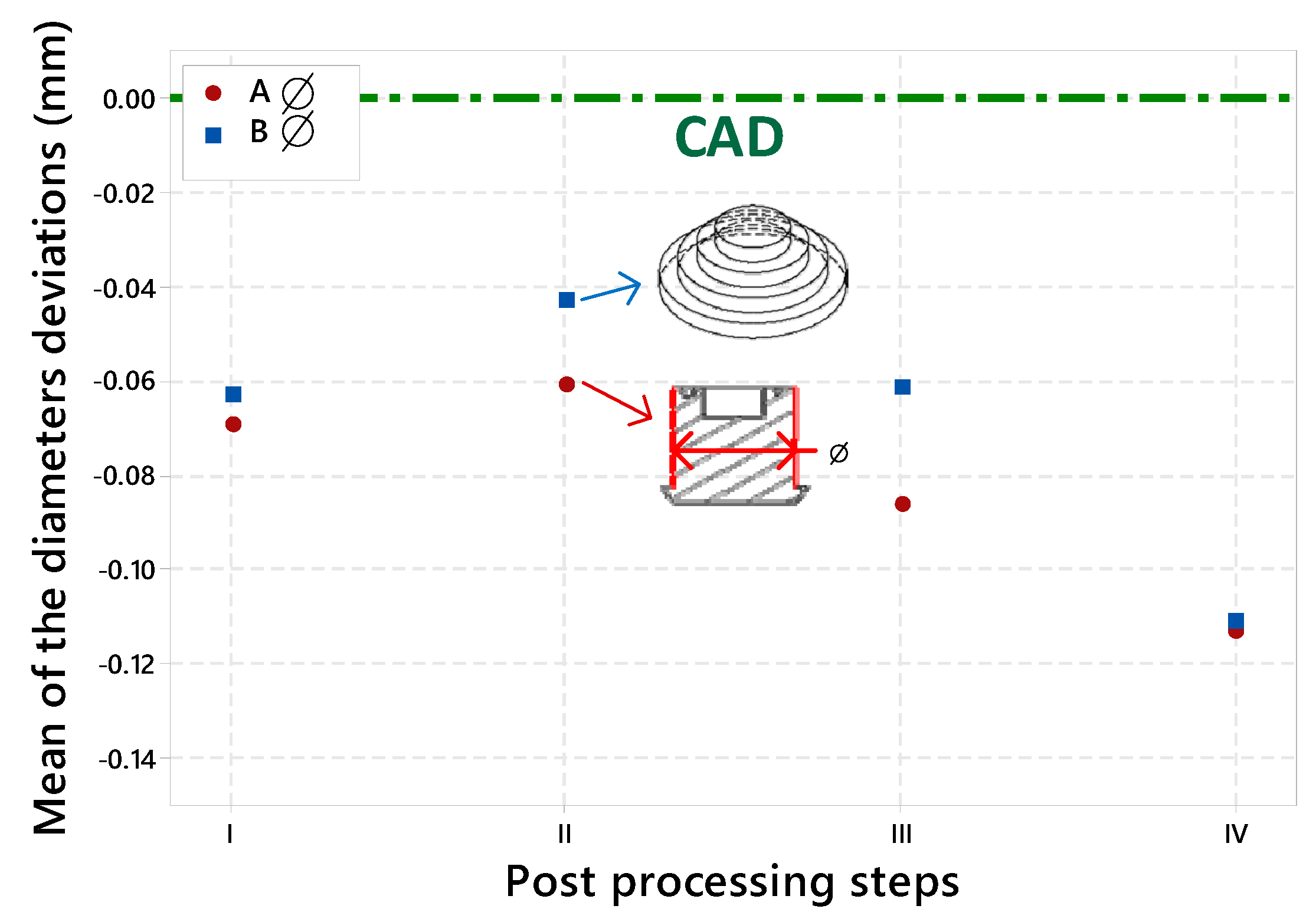
As mentioned before, there is a scale effect on the as-built parts, and SR has an effect proportional to the part scale. Those two facts result in a less severe scale effect between parts after SR, as observed in Figure 12. After stress relief, the part diameter deviations decrease at an average of +9 µm (II–I). After PR, each part shrinks for an average of −25 µm (III–II). After shot peening, the shrinkage of each part diameter increases for an average of −27 µm (IV–III). This evolution of the diameters means deviations at each PPS can be observed in Figure 15.
However, the scale effect remains after all the PPSs for the part having the greater material concentration: the Shape A (P1) artifact (Figure 12). Collecting more data is needed to confirm that the scale effect is more persistent to the PPS on the massive shapes.

3.5.2. Shape B Artifact

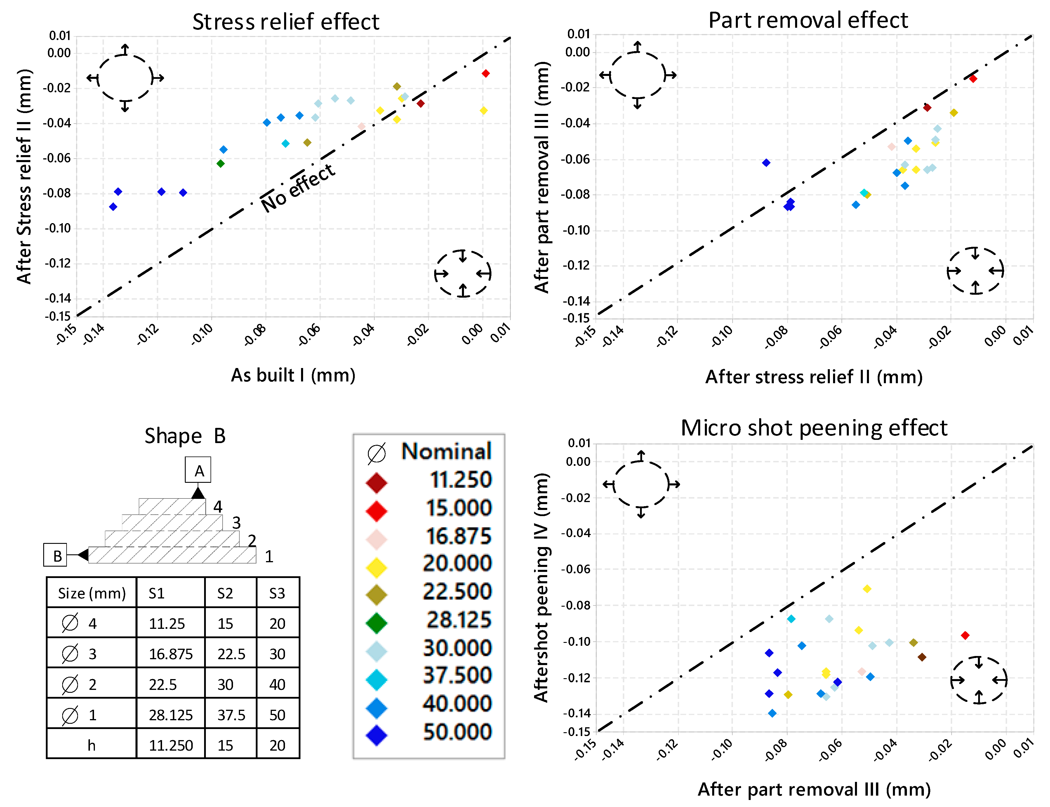
Figure 13 presents the diameter deviation of the Shape B artifact at each PPS. Each colour represents one size of nominal diameter and each point represents a distinct diameter. There are 6 parts (all Shape B artifacts) × 4 (diameters at each of the four steps of the pyramidal shape of one part), which makes 24 represented points. The 24 diameter deviations are presented at each PPS. The streaked line is a no-effect line, which means that a point on this line has not changed during the presented post-processing. The graph highlights the PPS effects.
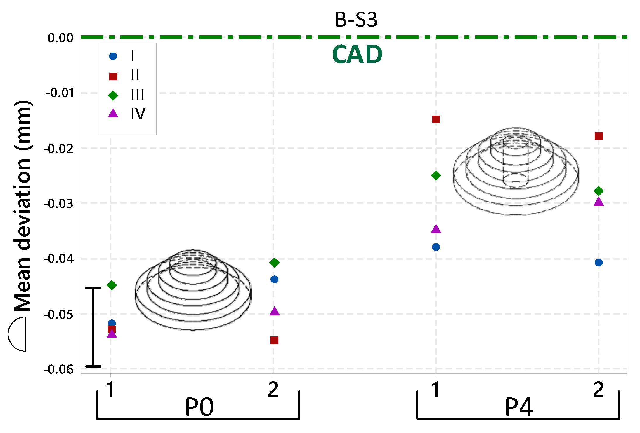
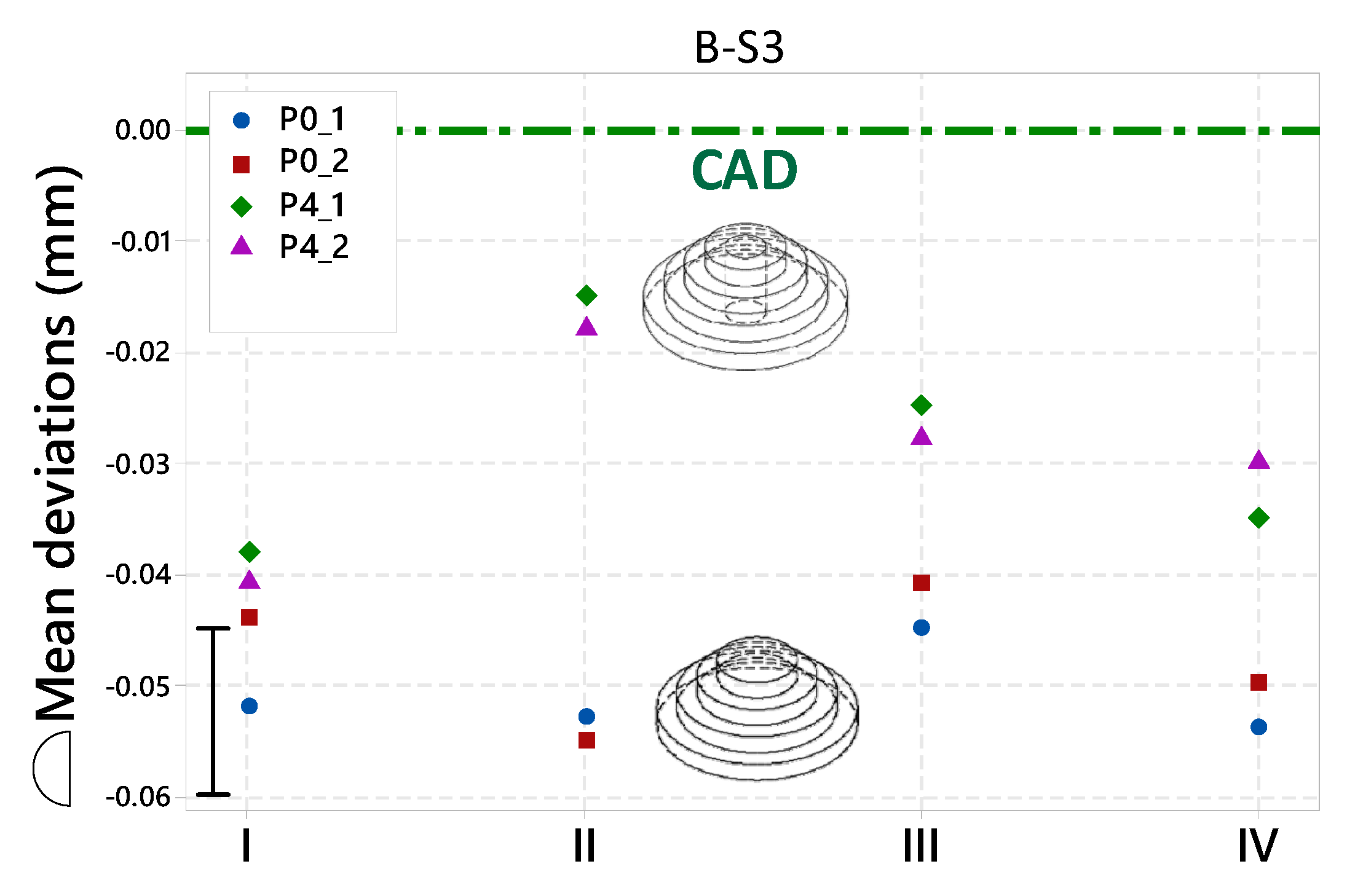
Figure 14 presents the 3D profile mean deviation of four Shape B artifacts at S3, with two of them having a pocket (P4) and the two others, without pockets (P0). Each column represents the deviation of the four parts at one PPS. Each color represents one part. This figure highlights the PPS effect on the overall 3D profile deviation depending on the material concentration.
We can observe in Figure 13 that the deviations trend, depending on the diameter scale, is highly affected by the PPSs. As observed earlier with the calibration part (Figure 5) and the Shape A artifact (Figure A2 of Appendix A), the stress relief heat treatment affects the dimensions of the artifact by an amplitude depending on their scales. The trend of the colours in Figure 13 (I/II) is highly correlated to the scale. Moreover, most of the points are above the no-effect line. This means that the diameters have expanded (at an average of +20 µm) after the stress relief. The points of Figure 13 (II/III) are under the no-effect line. This means that the diameters have decreased after the part removal (at an average of −19 µm). Also, the colour trend demonstrates a less pronounced scale effect. The points of Figure 13 (III/IV) are under the no-effect line. This means that the part diameters decreased after the micro shot peening (at an average of −49 µm). The evolution of the diameters means that deviations in the Shape B artifact at each PPS can be observed in Figure 15.
The part material concentration level seems to have a major effect on the deviation after the SR, as observed in Figure 14. For the same shape and scale, with the exception of a pocket, there is a difference in the 3D profile mean deviations of 9 µm as-built, but 38 µm after the SR.

4. Conclusions

This work is designed to isolate, evaluate and quantify the metrological performances of the laser powder bed fusion of metal powders. It presents and discusses an analysis performed on 18 specially designed artifacts printed using AlSi10Mg powder and an EOS M280 LPBF system. The study quantifies the intra- and inter- scale effects, the part material concentration effects, the printing deviations behaviour (I), the stress relief effect (II), the part removal effect (II) and the micro shot peening effect (IV) on the 3D profile deviations of the parts. Based on the obtained results, the following conclusions can be drawn:
(1)
There exists an intra-part scale effect; different features of the same part having different nominal sizes manifest different deviations.
(2)
For the parts of the same size, the lower the material concentration, the lower the number of observed deviations.
(3)
Stress relief heat treatment reduces the intra- and inter-part scale effects by expanding (MMC) the larger features more than the smaller features.
(4)
The parts removal operation globally increases the parts deviations.
(5)
Micro shot peening has a positive effect on the surface roughness, but systematically reduces the parts size.
The results of this study will serve as an accessible database of experimental values carried out according to the GD&T ASME Y14.5 (2009) standard. Therefore, they can be used to validate numerical models that aim to predict the geometrical and dimensional deviations of parts manufactured using the same process and machine, with the same powder. Enhancing the efficiency of the design for AM (DFAM) numerical models will have a positive impact on the competitiveness of AM and could boost its adoption by high-technology industries where the production cycle would greatly benefit from these technologies.

Author Contributions

The project objectives and methodology were proposed by A.T. and V.B. The specimen fabrication, scanning and data treatment were carried out by F.Z. with the help of A.T. and V.B. The article was written by F.Z. and revised by A.T. and V.B.

Funding

This research received no external funding.

Acknowledgments

The authors would like to thank École de technologie supérieure (ETS) for their support. The authors are thankful to Joel Grignon, Salah Eddine Brika, Jean-René Poulin and Ali Aidibe, who assisted in the research.

Conflicts of Interest

The authors declare no conflicts of interest.

Appendix A

Analysis C—Part Material Concentration Effect
Shape B Artifact
Figure A1 presents the 3D profile mean deviation of four Shape B artifacts, at the S3, with two of them having a pocket (P4) and the two others not having some pockets (P0). Each column represents the measurements at the four PPSs of the same part. This figure highlights the material repartition effect on the overall 3D profile deviation.
Figure A1. Three-dimensional (3D) profile mean deviations of the Shape B artifact having the biggest size (S3); Scan I (as-built); Scan II, after stress relief; Scan III, after part removal; and Scan IV, after shot peening.
Jmmp 03 00049 g0a1
The 3D profile mean deviation study of four Shape B artifacts, with two of them having a P0 and the other two a P4, reveals a clear relationship between the part material concentration and the overall 3D profile deviation. Indeed, for the same shape and scale, with the exception of a pocket, there is a difference in the 3D profile mean deviations of –9 µm as-built, –38 µm after SR, –16 µm after part removal and –19 µm on the final part (after micro shot peening), for the P0 artifacts, in the Least Material Condition (LMC) direction. The artifacts with a higher material concentration (P0 cylinders) always showed a greater number of deviations than artifacts with a lower material concentration (P4 cylinders), as observed on the Shape A artifact (Figure 9).
Analysis D—Post-Processing Effects
Shape A Artifact
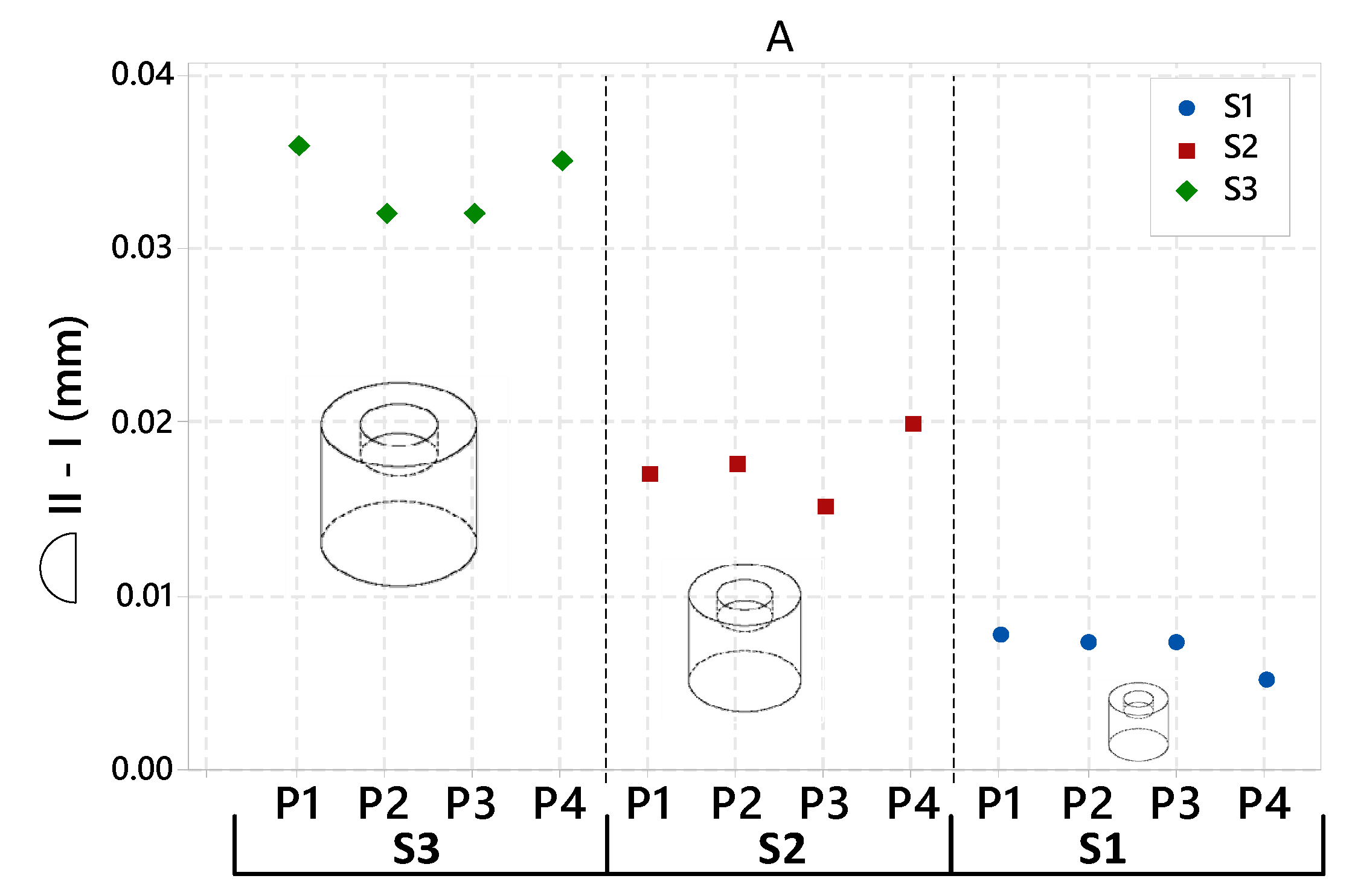
Figure A2 presents the difference between the overall 3D profile mean deviation of the 12 Shape A artifacts before (I) and after the stress relief (II). Each point represents the evolution after the SR (after SR - before SR). The graph highlights the SR effects on the overall deviation depending on the part scale.
Figure A2. Stress relief effect depending on the feature nominal size for the 12 Shape A artifacts; S1–S3 part size.
Jmmp 03 00049 g0a2
The difference between the overall 3D profile mean deviation of the 12 Shape A artifacts before (I) and after stress relief (II) shows that the stress relief effect is proportional to the part scale (Figure A2). The S3 part deviations decrease by an average of +34 µm after SR, the S2 parts deviations decrease by +17 µm and the S1 parts deviations decrease by +7 µm. These results align with the previous observations on the calibration part.

Appendix B

The mean values of the overall 3D profile deviation of each part used for this study, including the calibration part, are displayed in Table A1 and Table A4. The deviations are given at each PPS.
Table A1. Calibration part inspection results.
CAD (mm)IDIIIII-I
(mm)%(mm)%(mm)%
701−0.084−0.12%0.0120.02%0.0960.14%
302−0.06−0.20%−0.033−0.11%0.0280.09%
603−0.071−0.12%−0.011−0.02%0.0590.10%
204−0.042−0.21%−0.013−0.07%0.0290.15%
505−0.057−0.11%0.0160.03%0.0730.15%
506−0.096−0.19%−0.022−0.04%0.0740.15%
507−0.063−0.13%0.0090.02%0.0720.14%
508−0.075−0.15%0.0080.02%0.0830.17%
1.590.0674.47%0.0644.27%−0.003−0.20%
Table A2. Three-dimensional (3D) profile ( Jmmp 03 00049 i001) mean deviations ( μ ^ ) of Shape A artifacts at each post-processing step (as-built I, after stress relief II, after part removal III and after micro shot peening IV).
μ ^ (mm)S3PPSP1P2P3P4
I−0.088−0.07−0.065−0.065
II−0.052−0.038−0.033−0.03
III−0.0527−0.04−0.048−0.035
IV−0.063−0.05−0.058−0.047
S2PPSP1P2P3P4
I−0.045−0.0355−0.0411−0.0459
II−0.028−0.018−0.0261−0.0261
III−0.047−0.0311−0.0337−0.0409
IV−0.05−0.0399−0.0415−0.0462
S1PPSP1P2P3P4
I−0.0471−0.043−0.0476−0.03
II−0.0394−0.0357−0.0403−0.025
III−0.0535−0.0372−0.049−0.0358
IV−0.0568−0.0508−0.0558−0.0375
Table A3. External diameter ( ϕ ) deviations of Shape A artifacts at each post-processing step (as-built I, after stress relief II, after part removal III and after micro shot peening IV).
ϕ (mm)S3PPSP1P2P3P4
(mm)%(mm)%(mm)%(mm)%
I−0.128−0.43%−0.104−0.35%−0.106−0.35%−0.093−0.31%
II−0.089−0.30%−0.083−0.28%−0.079−0.26%−0.07−0.23%
III−0.092−0.31%−0.107−0.36%−0.121−0.40%−0.079−0.26%
IV−0.123−0.41%−0.122−0.41%−0.114−0.38%−0.109−0.36%
S2PPSP1P2P3P4
(mm)%(mm)%(mm)%(mm)%
I−0.042−0.21%−0.062−0.31%−0.07−0.36%−0.071−0.36%
II−0.052−0.26%−0.049−0.25%−0.06−0.30%−0.062−0.31%
III−0.085−0.43%−0.08−0.40%−0.06−0.30%−0.079−0.40%
IV−0.116−0.58%−0.11−0.55%−0.11−0.57%−0.129−0.65%
S1PPSP1P2P3P4
(mm)%(mm)%(mm)%(mm)%
I−0.027−0.27%−0.041−0.41%−0.057−0.57%−0.033−0.33%
II−0.042−0.42%−0.048−0.48%−0.057−0.57%−0.04−0.40%
III−0.072−0.72%−0.089−0.89%−0.08−0.80%−0.09−0.90%
IV−0.11−1.10%−0.111−1.11%−0.116−1.16%−0.09−0.90%
Table A4. Three-dimensional (3D) profile ( Jmmp 03 00049 i001) mean deviations ( μ ^ ) of Shape B artifacts at each post-processing step (as-built I, after stress relief II, after part removal III and after micro shot peening IV).
μ ^ (mm)S3PPSP0-1P0-2P4-1P4-2
I−0.052−0.044−0.038−0.041
II−0.053−0.055−0.015−0.018
III−0.045−0.041−0.025−0.028
IV−0.054−0.05−0.035−0.03
S2PPSP4
I−0.026
II−0.002
III−0.024
IV−0.027
S1PPSP4
I−0.039
II−0.021
III−0.016
IV−0.032

References

  1. Standard, A. ISO/ASTM 52900: 2015 Additive Manufacturing-General Principles-Terminology; ASTM F2792-10e1; ASTM: West Conshohocken, PA, USA, 2012. [Google Scholar]
  2. DIN, E. ISO/ASTM 52900: 2017-06 Additive Manufacturing—General Principles—Terminology (ISO/ASTM 52900: 2015); German Version EN ISO/ASTM; ASTM: West Conshohocken, PA, USA, 2017. [Google Scholar]
  3. Moylan, S.; Slotwinski, J.; Cooke, A.; Jurrens, K.; Donmez, M.A. Proposal for a standardized test artifact for additive manufacturing machines and processes. In Proceedings of the 2012 Annual International Solid Freeform Fabrication Symposium, Austin, TX, USA, 6–9 August 2012. [Google Scholar]
  4. Richter, J.; Jacobs, P. Rapid Prototyping & Manufacturing. Soc. Manuf. Eng. 1992, 12, 287–315. [Google Scholar]
  5. Byun, H.-S.; Lee, K.H. Design of a new test part for benchmarking the accuracy and surface finish of rapid prototyping processes. In Proceedings of the International Conference on Computational Science and Its Applications—ICCSA 2003, Montreal, QC, Canada, 18–21 May 2003; pp. 731–740. [Google Scholar]
  6. Kruth, J.P.; Vandenbroucke, B.; Van Vaerenbergh, J.; Mercelis, P. Benchmarking of different SLS/SLM processes as rapid manufacturing techniques. In Proceedings of the International Conference on Polymers and Moulds Innovations (PMI), Gent, Belgium, 20–23 April 2005. [Google Scholar]
  7. Loose, K.; Nakagawa, T. Benchmarking various methods of layer manufacturing systems in Rapid Prototyping. In Proceedings of the 15th Rapid Prototyping Symposium, Japan Society of Die and Mould Technology (JSDMT), Tokyo, Japan, November 1998. [Google Scholar]
  8. Zhou, J.G.; Herscovici, D.; Chen, C.C. Parametric process optimization to improve the accuracy of rapid prototyped stereolithography parts. Int. J. Mach. Tools Manuf. 2000, 40, 363–379. [Google Scholar] [CrossRef]
  9. Bakar, N.S.A.; Alkahari, M.R.; Boejang, H. Analysis on fused deposition modelling performance. J. Zhejiang Univ. Sci. A 2010, 11, 972–977. [Google Scholar] [CrossRef]
  10. Fahad, M.; Hopkinson, N. A new benchmarking part for evaluating the accuracy and repeatability of Additive Manufacturing (AM) processes. In Proceedings of the 2nd International Conference on Mechanical, Production and Automobile Engineering (ICMPAE 2012), Singapore, 28–29 April 2012. [Google Scholar]
  11. Thompson, M.K.; Mischkot, M. Design of test parts to characterize micro additive manufacturing processes. Procedia CIRP 2015, 34, 223–228. [Google Scholar] [CrossRef]
  12. Aubin, R.F. A World Wide Assessment of Rapid Prototyping Technologies; United Technologies Research Center Report; United Technologies Research Center: East Hartford, CT, USA, 1994. [Google Scholar]
  13. Fernandez-Vicente, M.; Canyada, M.; Conejero, A. Identifying limitations for design for manufacturing with desktop FFF 3D printers. Int. J. Rapid Manuf. 2015, 5, 116–128. [Google Scholar] [CrossRef]
  14. Lanzotti, A.; Del Giudice, D.M.; Lepore, A.; Staiano, G.; Martorelli, M. On the geometric accuracy of RepRap open-source three-dimensional printer. J. Mech. Des. 2015, 137, 101703. [Google Scholar] [CrossRef]
  15. Meisel, N.; Williams, C. An investigation of key design for additive manufacturing constraints in multimaterial three-dimensional printing. J. Mech. Des. 2015, 137, 111406. [Google Scholar] [CrossRef]
  16. Islam, M.N.; Sacks, S. An experimental investigation into the dimensional error of powder-binder three-dimensional printing. Int. J. Adv. Manuf. Technol. 2016, 82, 1371–1380. [Google Scholar] [CrossRef]
  17. Kniepkamp, M.; Fischer, J.; Abele, E. Dimensional accuracy of small parts manufactured by micro selective laser melting. In Proceedings of the 27th Annual International Solid Freeform Fabrication Symposium, Austin, TX, USA, 8–10 August 2016. [Google Scholar]
  18. Singh, S.; Sharma, V.S.; Sachdeva, A. Optimization and analysis of shrinkage in selective laser sintered polyamide parts. Mater. Manuf. Process. 2012, 27, 707–714. [Google Scholar] [CrossRef]
  19. Huang, Q.; Nouri, H.; Xu, K.; Chen, Y.; Sosina, S.; Dasgupta, T. Statistical predictive modeling and compensation of geometric deviations of three-dimensional printed products. J. Manuf. Sci. Eng. 2014, 136, 061008. [Google Scholar] [CrossRef]
  20. Zongo, F.; Tahan, A.; Aidibe, A.; Brailovski, V. Intra-and inter-repeatability of profile deviations of an AlSi10Mg tooling component manufactured by laser powder bed fusion. J. Manuf. Mater. Process. 2018, 2, 56. [Google Scholar] [CrossRef]
  21. Calignano, F.; Lorusso, M.; Pakkanen, J.; Trevisan, F.; Ambrosio, E.P.; Manfredi, D.; Fino, P. Investigation of accuracy and dimensional limits of part produced in aluminum alloy by selective laser melting. Int. J. Adv. Manuf. Technol. 2017, 88, 451–458. [Google Scholar] [CrossRef]
  22. Van Bael, S.; Kerckhofs, G.; Moesen, M.; Pyka, G.; Schrooten, J.; Kruth, J. Micro-CT-based improvement of geometrical and mechanical controllability of selective laser melted Ti6Al4V porous structures. Mater. Sci. Eng. A 2011, 528, 7423–7431. [Google Scholar] [CrossRef]
  23. Li, C.; Sun, S.; Liu, C.; Lu, Q.; Ma, P.; Wang, Y. Microstructure and mechanical properties of TiC/AlSi10Mg alloy fabricated by laser additive manufacturing under high-frequency micro-vibration. J. Alloys Compd. 2019, 794, 236–246. [Google Scholar] [CrossRef]
  24. Liu, B.; Kuai, Z.; Li, Z.; Tong, J.; Bai, P.; Li, B.; Nie, Y. Performance Consistency of AlSi10Mg Alloy Manufactured by Simulating Multi Laser Beam Selective Laser Melting (SLM): Microstructures and Mechanical Properties. Materials 2018, 11, 2354. [Google Scholar] [CrossRef] [PubMed]
  25. Del Re, F.; Contaldi, V.; Astarita, A.; Palumbo, B.; Squillace, A.; Corrado, P.; Di Petta, P. Statistical approach for assessing the effect of powder reuse on the final quality of AlSi10Mg parts produced by laser powder bed fusion additive manufacturing. Int. J. Adv. Manuf. Technol. 2018, 97, 2231–2240. [Google Scholar] [CrossRef]
  26. Panda, B.K.; Sahoo, S. Thermo-mechanical modeling and validation of stress field during laser powder bed fusion of AlSi10Mg built part. Results Phys. 2019, 12, 1372–1381. [Google Scholar] [CrossRef]
  27. Aidibe, A.; Tahan, A.; Brailovski, V. A Novel Industrial Test Artifact for the Evaluation of Dimensional Capabilities of Metallic Additive Manufacturing Systems. In Proceedings of the European Powder Metallurgy Association (EPMA)—Euro PM2018, Bilbao, Spain, 14–18 October 2018; p. 6. [Google Scholar]
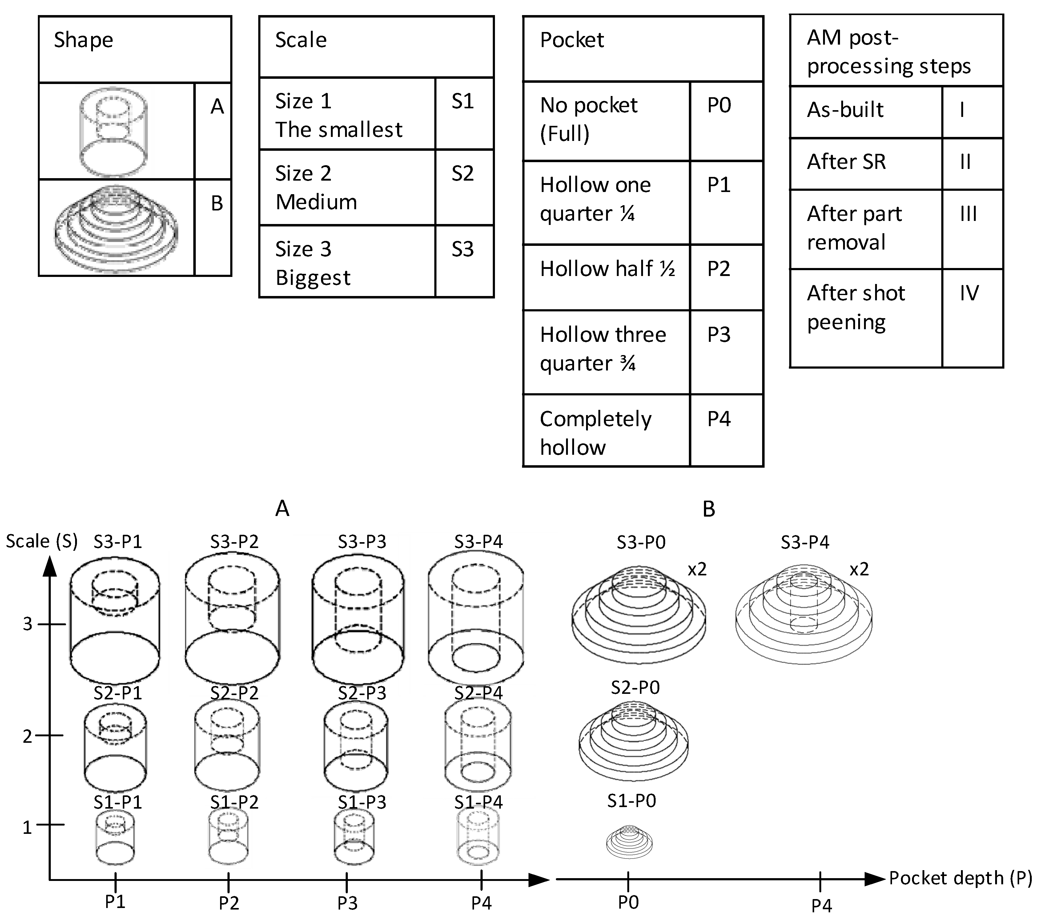
Figure 1. Variants of test artifacts.
Jmmp 03 00049 g001
Figure 2. Experimental protocol: (a) Beam offset correction, (b) Test artifacts GDEs.
Jmmp 03 00049 g002
Figure 3. Features inspected with nominal dimensions indicated in tables. (a) Shape A (b) Shape B.
Jmmp 03 00049 g003
Figure 4. (a) Calibration part inspection plan, (b) nominal values of the inspected features, and (c) inspection results.
Jmmp 03 00049 g004
Figure 5. Stress relief effect depending on the feature’s nominal size.
Jmmp 03 00049 g005
Figure 6. Intra-part scale effects of the Shape B artifacts carried out as-built, based on their cylinders’ diameters.
Jmmp 03 00049 g006
Figure 7. Inter-parts scale effects of Shape A artifacts (as-built state), based on their external diameter (highlighted in red).
Jmmp 03 00049 g007
Figure 8. Nonparametric cumulative distribution functions of four Shape B artifacts with no pockets (P0), carried out after part removal.
Jmmp 03 00049 g008
Figure 9. Three-dimensional (3D) profile mean deviations of the Shape A artifact having the biggest size S3 at each post-processing step; Scan I as-built; Scan II after stress relief; Scan III after part removal; and Scan IV after micro shot peening.
Jmmp 03 00049 g009
Figure 10. Nonparametric distribution function 95% interval of the 12 Shape A artifacts carried out as-built (blue) and after stress relief (red).
Jmmp 03 00049 g010
Figure 11. Three-dimensional (3D) profile mean deviations of the Shape A artifact having the biggest size S3, carried out at each post-processing step (as-built I, after stress relief II, after part removal III and after micro shot peening IV); P1–P4 pocket depths.
Jmmp 03 00049 g011
Figure 12. External diameter deviations of 12 Shape A artifacts at each post-processing step (as-built I, after stress relief II, after part removal III and after micro shot peening IV); P1–P4 pocket depth.
Jmmp 03 00049 g012
Figure 13. Post-processing step effects on the external diameter of 12 Shape B artifacts.
Jmmp 03 00049 g013
Figure 14. Three-dimensional (3D) profile mean deviations of the Shape B artifact having the biggest size (S3); P0–P4 designate the absence or the presence of a pocket.
Jmmp 03 00049 g014
Figure 15. The mean of the mean diameter deviation of each shape at each post-processing step.
Jmmp 03 00049 g015