Abstract
Producing metallic bipolar plates for Proton Exchange Membrane (PEM) fuel cells by forming is still a topic of research. So far, it has mainly been applied for small batches, but it offers substantial advantages regarding both costs and installation space compared to the established graphite based solutions. One new possibility for an efficient manufacturing process of these metallic bipolar plates is the forming by rolling. For the first time, this technology was used for relevant industrial scale channel geometries. By the use of an experimental rolling mill, 0.1 mm thick 316L (1.4404) stainless steel foils were roll-formed to achieve previously designed channel geometries within one rolling pass. The conducted experiments show promising results regarding the forming accuracy and the shape of the channel cross-sections. With the aim for a proof of concept in the beginning and a subsequent optimization of the process, a numerical simulation was set up prior to the real experiments and later calibrated with the experimental forming results. This calibrated model was used for further improvements of the process with the objective at reducing wrinkles and distortion. The investigation of this new process method for the manufacturing of metallic bipolar plates shows enormous potential and can lead to a more efficient and cheaper production.
1. Introduction
With reference to the challenges of rising energy requests in the technological and transportation sector, the demand of resource efficiency and environmentally friendly technologies has intensified enormously. Within these topics, alternative drive solutions are one of the most important aims to limit polluting exhausts produced by conventional combustion engines. Besides full battery electric vehicles in the short and middle range sector, fuel cells are a promising alternative, which offer long-range mobility, short refuelling cycles and zero emission during operation. One major problem that prevents a widespread market penetration is the cost for the production of fuel cell components, which are needed for a whole stack. Bipolar plates are one of these components, which would be required in an amount of approximately 700 half plates to assemble a complete fuel cell stack. Furthermore, bipolar plates have to meet high standards concerning corrosion and contact resistance, which results in expensive materials like titanium and gold coatings or time consuming complex production technologies such as hot pressing with subsequent precision milling operations. For this reason, stainless steel bipolar plates are one possible option to reduce both, material and production costs. Furthermore, several restrictions were made regarding the plate design to achieve a compromise between high energy density, flow conditions of cell media and a reduced assembly space [1]. Several technologies are available to form metallic bipolar plates, such as hydromechanical deep drawing [2,3], deep drawing with rigid dies [4,5], rubber pad forming [6,7] or special technologies like casting [8] and single point incremental forming [9]. While the mentioned manufacturing technologies of metallic bipolar plates already work well for small lot sizes [10], these methods have not been established for mass productions yet. One new possibility to enhance the productivity is given by the roll forming technology. Abeyrathna and Zhang made some first experiments according to rolling with several roll stands in one line, as known for profile rolling applications. An advantage of this technology is the reduced thinning compared to conventional deep drawing processes. However, up to now, it has not been possible to use this process for complete bipolar plate structures because it is just feasible for continuous geometries and not for closed structures. Furthermore, the plateaus on the top and the bottom of the formed geometry are still not even, which is unfavourable for further operations like welding and assembly [11,12]. In order to cope with these limitations this new roll forming strategy was developed and used for the first time to produce channels with industrial relevant scaled geometries for bipolar plates by forming 0.1 mm thick 316L (1.4404) metal foils. In the following paper, the experiments and numerical simulations are described, evaluated and improved to provide an outlook for the ongoing technological development.
2. Materials and Methods
The material used for the forming experiments is a commercial 316L (1.4404) stainless steel with a thickness of 0.1 mm and a provided chemical composition as shown in Table 1. The used coil was cold rolled and annealed to achieve an average grain diameter of 19.3 µm.

Table 1.
Chemical composition of 316L metal foils.
All specimen were cut from a coil with a stationary mechanical precision shear to the size of 52 mm × 28 mm. The rolling experiments were performed on a Duo/Quarto EW 105 × 100 strip rolling mill (Bühler und Co GmbH, Pforzheim, Germany). For the use of roll forming bipolar plate channels, adjustments had to be made on the working rolls. Within a turning and milling centre (NILES N20 MC2000, Chemnitz, Germany), pockets had to be machined in both of the roller tools, for the inserts with the geometrical structures of the bipolar plate channels (Figure 1).
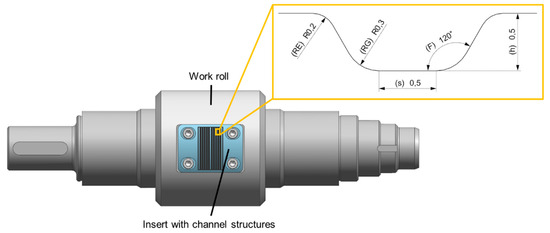
Figure 1.
Work roll with insert for roll forming of bipolar plate channel geometries (die) and enlarged drawing of the channel cross section (die).
The inserts were manufactured within a precision machining centre (Kern Pyramid Nano, Eschenlohe, Germany) in two main steps and eight intermediate steps in total. The first cutting step was done with an end mill (diameter: 11.63 mm) to provide the curved structure for the adjustment of the inserts to the exact diameter of the work rolls (105 mm). The machining parameters were set as follows: cutting speed (vc): 120 m/min, spindle speed: 3183 rpm and a feed (F) per revolution of 0.24 mm. The precision machining was done in seven subsequent steps with different spherical cutters reduced by diameter from 2 mm to 0.5 mm in the final steps. The parameters were set, descending from the first to the final precision machining steps, as follows: vc: 251 m/min to 63 m/min; spindle speed: 20,000 rpm to 40,000 rpm and F per revolution: 0.1 mm to 0.025 mm. Both manufactured inserts were fixed by screws in the provided pockets of each work roll, which were afterwards installed back into the rolling mill. The geometry of the inserts (Figure 1: cross section of the die) was designed with reference to actual metallic bipolar plate geometries with a drawing gap of 0.12 mm (0.1 mm sheet thickness, 0.02 mm offset). The dimensions of the die were given with: RE (entry radius): 0.2 mm, RG (ground radius): 0.3 mm, F (flank angle): 120°, s (channel width): 0.5 mm and h (height): 0.5 mm. To ensure an optimal alignment of the roll forming tools, pressure measurement foils (Medium Pressure (MS) Measurement Film, FUJIFILM Holdings K.K.) were used to position punch and die with the correct gap of 0.12 mm in all directions. The rolling gap (Figure 2(1)) can be adjusted manually by a wheel (Figure 2(3)) in 0.01 mm steps. For the conducted roll forming passes, the rolling gap was set to 0.12 mm with a roller speed of 3.1 rpm. The cut specimen was handled manually on a table in front of the rolling gap (Figure 2(2)) and then processed automatically by the friction between the sample and the channel geometries on the inserts of the working rolls.
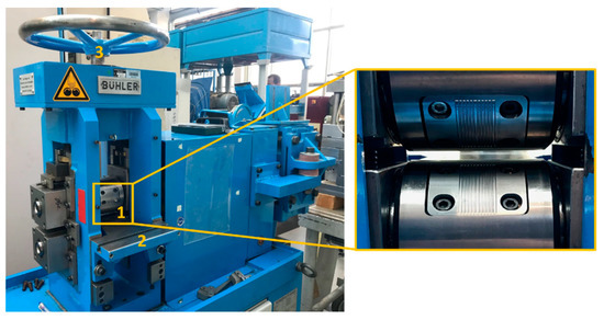
Figure 2.
Experimental setup of the roll forming process. (1) rolling gap; (2) roll table; (3) adjustment wheel.
The numerical simulations of the roll forming process were used to give proof of concept prior to the experimental try-outs on the one hand. On the other hand, the FEM was used to improve the process output and the sample quality after the successful calibration. Due to the complex incremental tool contacts in the roll forming process, simufact.forming 15.0 [13] was used to carry out the numerical analysis. To perform an identical simulation of the real process, all properties, which were needed as material data within the numerical simulation, were determined from different material tests with samples of the same coil, which were later used for forming experiments. The flow curve was calculated from bulge tests (Figure 3) and the anisotropy r-values were gained from tensile tests (r0 = 0.51; r45 = 1.45; r90 = 0.98).
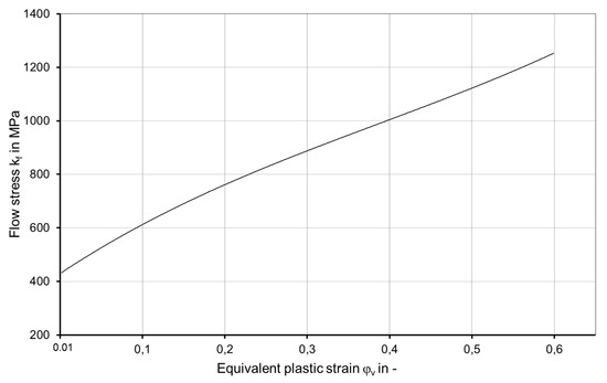
Figure 3.
Flow curve form bulge tests for 316L (1.4404), thickness: 0.1 mm.
All geometries constructed for the machining of the work rolls and inserts were simplified and transferred into the numerical simulation via the STEP exchange format (Figure 4). Additionally, a pusher was designed to overcome the roller feed in the FEM model.
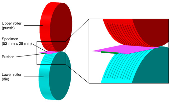
Figure 4.
FEM setup of roll forming in simufact.forming 15.0.
Process parameters such as rolling gap, rotation speed and temperatures (room temperature) were adopted from the experimental tests. At the end of the simulation, the workpiece was released from the tools to enable a free springback. A combined friction model was used with the values of µ = 0.1 for coulomb and m = 0.2 for the shear friction factor. By the use of this friction law, low contact stresses automatically lead to the coulomb formulation that is characteristic for rolling processes, whereas higher contact stresses are combined with the shear-friction model. For an exact discretization of the specimen, the sheet-mesher for hexahedral volume elements was applied with edge lengths of 0.25 mm and three elements in thickness direction. An automatic adaptive remeshing was set at a plastic strain of 0.4. To fasten the numerical calculation, the model was divided on four cores via DDM parallelization function.
3. Results and Discussion
3.1. Preliminary Numerical Analysis and Experimental Studies of the Roll Forming Process
The numerical simulation in advance to the experimental tests has demonstrated the feasibility of the roll forming process for the forming of relevant bipolar plate channel geometries. The specimen was processed successfully by the roller geometries and first characteristics were visible (Figure 5).
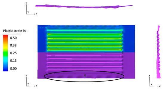
Figure 5.
FEM results (geometry (purple) and plastic strain) of the roll forming process. (1) wrinkles.
The macroscopic geometrical shape shows that the roll forming of the channels has been successful and the designed properties are clearly formed in the initial metal foil. The evaluation of the equivalent plastic strain shows some maximum values of φ = 0.36 and an average of φ = 0.27 for the radii and channel flanks (Figure 5). Furthermore, eight first type wrinkles were visible on each side in x-direction within the peripheral areas next to the flow field of the specimen (Figure 5(1)). Another phenomenon in sheet metal forming processes is the springback effect, which can be seen in both, x-direction and y-direction. This kind of springback effect is typical for the forming of metal foils by deep drawing and leads to an uneven specimen geometry, where problems in further operations like welding or assembling can occur. One further geometric uncertainty is the bending of the specimen, which normally appears within rolling processes and which in this case is caused by the small diameter of the work rolls (105 mm) and the rotational rolling kinematic. Compared to the CAD construction, the deviation in four defined points at the edges of the flow field (0.5 mm diagonal from the outer channel geometries) becomes clearly visible with a maximum distance of 1.10 mm between construction and simulated result and can be seen in the different views too (Figure 6).

Figure 6.
Comparison between FEM result of roll forming (blue) and CAD construction (green).
However, the numerical simulation proved, that the process of rolling this industrial shape bipolar plate channels in general works good, which leads to the conclusion that experimental tests have to be done, to prove the feasibility for the real process too.
In accordance to the geometries and parameters described above, the experimental tests were performed. The experiments showed equivalent results to the numerical simulations, which leads to the fact that the prediction of the numerical simulations worked very well. The channel geometries were successfully formed in the 0.1 mm metal foils by rolling, while the other geometrical characteristics, which can be seen in the numerical results (Figure 5), occurred in the experiments too (Figure 7).
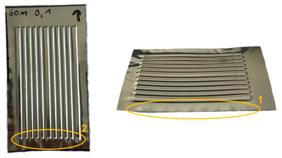
Figure 7.
Experimental roll forming results. (1); wrinkles over length (2) wrinkles over width.
A first optical analysis offers an almost identical look, as seen in the FEM results. The eight first grade wrinkles (Figure 7(1)), spread over the peripheral areas on each side over the length of the specimen, occur in the same way, as in the numerical prediction. Other forming effects, which were visible for the simulation and the experiments, are the springback effect after the release of the tools and the bending of the specimen, which directly appears during the roll forming. One effect, which is not visible in the numerical simulation are the wrinkles over the width of the specimen (Figure 7(2)). These wrinkles are limited to the experiments because there is a small offset in the radial position of the rollers, which leads to the effect that the gap in the entry area of the inserts is smaller, than in the outlet area. This means that the material in the outlet area is less restricted by geometrical boundaries and can deform in an undefined way, which also results in small wrinkles. A further challenge is given by the exact positioning of the specimen in front of the rollers. Minimal variances of the position in width and length lead to oblique or incompletely formed specimen.
Other important geometrical values are the channel height and the remaining thickness of the formed workpiece. For the influence on the channel height, the rolling gap can be adjusted. In this case, the rolling gap was set to the initial thickness of the metal foils added with 20 µm offset (0.12 mm). Another characteristic of these forming processes is the thinning effect in the radii and flanks of the channel structures. To examine the detailed effects, microsections were made and analysed under the microscope. The results show channel cross-sections, with an average height (h) of 0.32 mm and even plateaus at the tops and bottom of the channels (Figure 8).
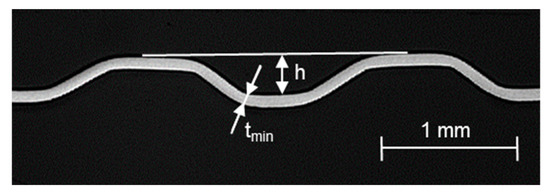
Figure 8.
Microsection of the roll formed channel cross-section (rolling gap: 0.12 mm).
Additionally it can be seen, that the formed structure of this setup developed without any significant thinning in the radii and flank areas and a minimum thickness (tmin) of 84.8 µm in one of the measured bottom radii (Figure 8). This means, that the roll forming process with the used parameters is in a very safe area regarding possible damage effects like cracks. Additionally, it has to be said, that a reduced rolling gap (< 0.12 mm) can lead to more extensive thinning.
3.2. Verification of the Numerical Roll Forming Model
For a further predictive use of the roll forming FEM model, an exact calibration has to be done. A general conformity between the simulated and the experimental geometries was directly visible for the comparison of the forming results (Figure 9).
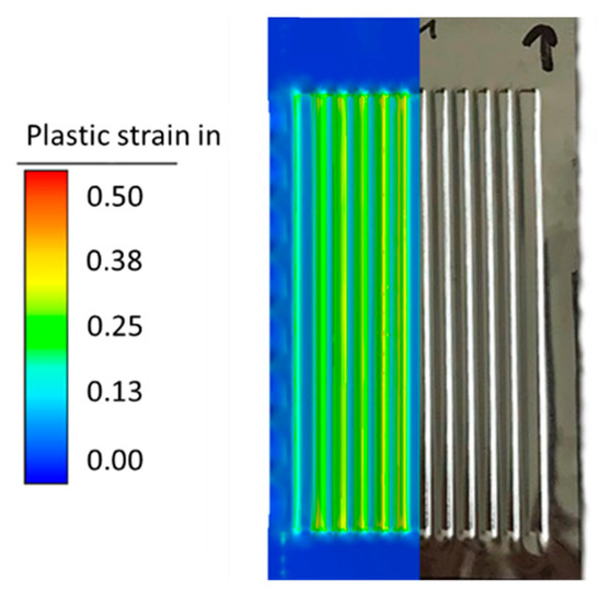
Figure 9.
Comparison between the roll forming results of FEM (plastic strain) and experiment.
As already stated, the wrinkles appear in the same amount and at the same location, which is again visible within Figure 9. For another more exact statement, the experimental samples were measured according to the macroscopic geometry and the thinning; to compare the values with the ones gained from the FEM. The results are shown in Table 2.

Table 2.
Comparison of roll forming results between experiment and FEM.
An additional measurement was done by means of the photogrammetry method (GOM ATOS Core, Braunschweig, Germany). This enables a direct comparison between the calculated numerical forming result (blue) and the experimental specimen (grey). Figure 10 shows a very good conformity for the geometrical shape, with a maximum deviation in the distance between both results of 0.29 mm.
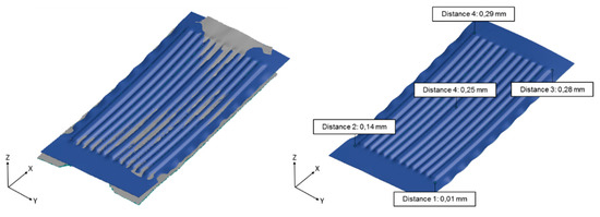
Figure 10.
(Left) Comparison between FEM result of roll forming (blue) and experiment (grey), (right) FEM geometry with distances to the experimental results.
To sum it all up, a good congruence was found between the numerical simulation and the experimental tests. The maximum deviation in the height of the channels (12.5%) seems to be relatively high concerning the percentage but in total difference, it is just 40 µm too. Nevertheless, especially the global geometrical accordance and the thickness development show a noticeably better conformity, which means, that the FE-model can be used for further process improvements. The remaining problems with the macroscopic shape of the specimen (wrinkles and bending) should be solved to improve the roll forming results.
3.3. Roll Forming Process Improvements
First of all, it was tested how the roll forming results develop if the material is processed with the initial rolling direction of the metal foil perpendicular to the roll forming direction (90°RD). It is relevant to know if it is necessary to consider the initial rolling direction of the 316L (1.4404) metal foils in the process setup, especially if it is planned to produce bipolar plates directly from the coil. The investigation was done directly in the numerical simulation with the calibrated model setup. So the rolling direction of the initial workpiece had to be changed while all of the other parameters remained the same. The forming results were compared with the numerical model, where the initial rolling direction of the metal foil is the same as the roll forming direction (0°RD). Figure 11 shows an almost identical geometry for the direct comparison.
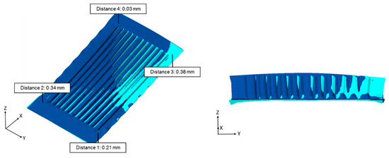
Figure 11.
Comparison between the FEM results of roll forming 0°RD (blue) and 90°RD (light green).
A more detailed look at the distances between both geometries clarifies the identical forming results with a maximum deviation of 0.38 mm. This means that the geometries show a slightly different springback effect after the release of the tools, but in general behave in the same way during the forming process. Therefore, the results show that the anisotropic characteristics of the initial material have no significant impact on the process results of the roll forming technology. For this reason, it can be stated that a production directly from the coil is possible with the used material and without any additional treatments or processes. Further improvement has to be done regarding the undesirable geometrical forming behaviour like wrinkles and the bent global structure of the workpieces.
Within deep drawing processes of metal foils, a binder can be used to enhance the quality of the products. For the roll forming process, this is not feasible. For this reason, a strip tension system was implemented numerically, to reduce the effects of wrinkling and bending within the roll forming process (Figure 12).
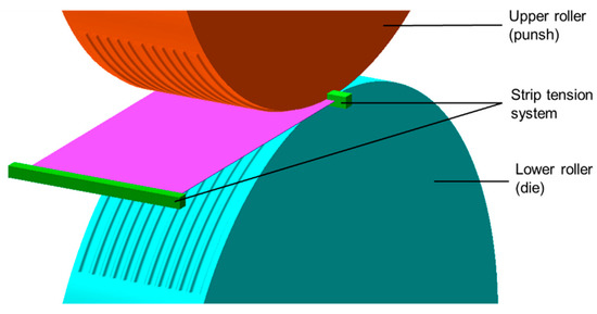
Figure 12.
FEM setup roll forming with strip tension.
Therefore, the speed of the workpiece was measured on both sides of the rolling process within the FE simulation, in front of the working rolls (entrance side) and behind the working rolls (outlet side). Both sides had to be measured because there is a different velocity of the unformed and formed material parts in conventional rolling processes. Normally the velocity for rolled products is lower on the entrance side, than on the outlet side, where the thickness is reduced. The reason is that the reduction in thickness and the related material displacement leads to a higher speed, when the thinner product leaves the rolling mill. Within the roll forming process, a different effect occurs. The material on the entrance side in front of the rolling gap shows a higher velocity (8.4 mm/s) than on the outlet side, after the forming of the specimen (8.2 mm/s). This is probably caused by the process characteristics of roll forming, where no thickness reduction of the initial material takes place, while the channel geometry is formed into the metal foil. This kind of forming process slows the velocity on the outlet side because the material flow does not take place in length direction but in height and width. For this purpose, the part of the geometry on the outlet side has a lower velocity than on the entrance side. However, to get a taut metal strip, the velocity of both strip tension elements was set to 8.2 mm/s, while all other process parameters stayed the same, like for the real process. A constant velocity of 8.2 mm/s causes tensile stresses during the roll forming process (Figure 13).
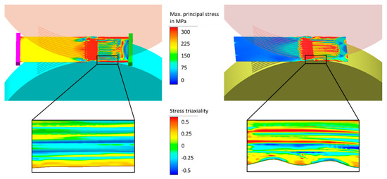
Figure 13.
Maximum principal stress during roll forming, (left) with strip tension, (right) without strip tension with enlargements of stress triaxiality.
These tensile stresses, shown by the maximum principal stress in Figure 13 enable a superposition with the compressive stresses in the wrinkled areas of the specimen, which occur during the roll forming process. While the specimen without strip tension shows values of around 5 MPa, the strip tension system increases the tensile stresses to 200 MPa. A closer look at the stress triaxiality in Figure 13 (enlargements) clarifies the mechanics behind the effects of stress superposition. On the one side, the roll forming without strip tension shows wrinkles with changing triaxiality values (−0.35: uniaxial compressive stresses and 0.43: almost uniaxial tensile stresses). On the other side, it can be seen that the roll forming setup with strip tension system only indicates positive values for the triaxiality (0.33: uniaxial tensile stresses). Therefore, it can be concluded that the superposition within the strip tension model causes a higher amount of constant tensile stresses to eliminate the compressive stresses, which occurs during wrinkling. For this reason, the strip tension also enlarges the stability of the whole specimen against distortion.
The numerical results show, that significant improvements were archived using the numerical simulated strip tension system. A look at the simulated geometry development shows an even result with just a few slight wrinkles over the length in the peripheral areas and without noticeable springback effects after the release from the tools (Figure 14).
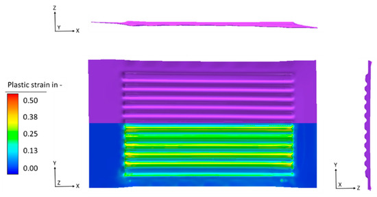
Figure 14.
FEM results (geometry (purple) and plastic strain) of the roll forming process with strip tension system.
Especially the fact, that the final bipolar plates were cut from the metal sheets after the forming process leads to the conclusion that the remaining small wrinkles in the outer areas of the specimen were of minor relevance regarding to the final product. The equivalent plastic strain develops in the same way, as seen for the roll forming without strip tension system with some peaks of φ = 0.39 at the channels front and back edges and an average of φ = 0.32 at the channel flanks. Furthermore, a small increase of thinning can be measured in the radii (thickness: 79.3 µm) and the channel flanks (thickness: 84.3 µm) compared to the forming process without strip tension system (thickness radii: 83.5 µm, channel flanks: 89.9 µm). This effect is also caused by the additional tensile stresses; applied for the process with strip tension system and therefore lead to the increased thinning. A more detailed analysis of the global geometry with a comparison to the CAD construction is shown in Figure 15.
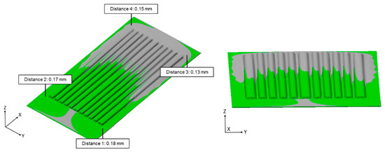
Figure 15.
Comparison between FEM result of roll forming with strip tension system (grey) and CAD construction (green).
It is clearly visible that the geometry, which was generated within the numerical calculation for the roll forming process with applied strip tension system, is in very good accordance to the constructed CAD geometry. A maximum deviation of 0.18 mm is noticeable less than the values, which were measured for the roll forming without strip tension. The exact comparison can be seen in Table 3.

Table 3.
Comparison between the numerical simulations of roll forming with and without strip tension system.
Overall, it can be concluded that the use of a strip tension system can clearly improve the workpiece quality of the roll forming process. This means that the roll forming process with strip tension system leads to results, which are comfortable to handle in subsequent operations like welding or the assembly of fuel cell stacks due to the geometrical improvements, which were achieved.
4. Conclusions
In summary, it was shown, that the roll forming process is feasible for industrial shape bipolar plate channel geometries. The numerical simulations as well as the experimental tests showed good results for the forming of the channel geometries (thinning etc.). Global forming side effects such as wrinkles and springback are visible for all specimens with the actual setup but the numerical improvements with a strip tension system showed promising results with a maximum reduction of 96.5% for the comparison with the CAD geometry. As a next step, the improvements have to be shown for real experiments by implementing a strip tension setup to the experimental rolling mill. Furthermore, some more complex geometrical shapes and bigger plates will have to be developed and tested for the roll forming of metallic bipolar plate geometries.
Author Contributions
Conceptualization, A.B.; Methodology, A.B., S.H.; Validation, A.B.; Investigation, A.B.; Writing—original draft preparation, A.B.; Writing—review and editing, B.A. and S.H.; Supervision, B.A. and S.H.
Funding
This research received no external funding.
Acknowledgments
The authors gratefully thank the Professorship for Forming and Joining of the Chemnitz University of Technology for providing the experimental rolling mill and the Professorship of Micromanufacturing Technology of the Chemnitz University of Technology for the help with the machining of the roller inserts.
Conflicts of Interest
The authors declare no conflict of interest.
References
- Peng, L.; Yi, P.; Lai, X. Design and manufacturing of stainless steel bipolar plates for proton exchange membrane fuel cells. Int. J. Hydrog. Energy 2014, 39, 21127–21153. [Google Scholar] [CrossRef]
- Maschinentechnik GmbH und Co. KG. Brennstoffzellen. Available online: http://www.graebener-maschinentechnik.de/Brennstoffzellen.gmt-brennstoffzellen.0.html (accessed on 3 December 2018).
- Osia, M.B.; Hosseinipour, S.J.; Bakhshi-Jooybari, M.; Gorgi, A. Forming metallic micro-feature bipolar plates for fuel cell using combined hydroforming and stamping processes. Iran. J. Energy Environ. 2013, 4, 87–94. [Google Scholar]
- Bong, H.J.; Lee, J.; Kim, J.-H.; Barlat, F.; Lee, M.-G. Two-stage forming approach for manufacturing ferritic stainless steel bipolar plates in PEM fuel cell: Experiments and numerical simulations. Int. J. Hydrog. Energy 2017, 42, 6965–6977. [Google Scholar] [CrossRef]
- Scherer, J. Enabling commercialization of high performance automotive stacks through integrated MBPP modules. In Proceedings of the World of Energy Solutions, Stuttgart, Germany, 12–14 October 2015. [Google Scholar]
- Elyasi, M.; Khatir, F.A.; Hosseinzadeh, M. Manufacturing metallic bipolar plate fuel cells through rubber pad forming process. Int. J. Adv. Manuf. Technol. 2017, 89, 3257–3269. [Google Scholar] [CrossRef]
- Jin, C.K.; Lee, K.H.; Kang, C.G. Performance and characteristics of titanium nitride, chromium nitride, multi-coated stainless steel 304 bipolar plates fabricated through a rubber forming process. Int. J. Hydrog. Energy 2015, 40, 6681–6688. [Google Scholar] [CrossRef]
- Jin, C.K.; Kang, C.G. Fabrication process analysis and experimental verification for aluminum bipolar plates in fuel cells by vacuum die-casting. J. Power Sources 2011, 196, 8241–8249. [Google Scholar] [CrossRef]
- Tebaay, M.; Sieczkarek, P.; Hahn, M.; Gies, G.; Tekkaya, A.E. Development of the incremental micro-forming process for small batch production of metallic bipolar plates. In Proceedings of the ASK Umformtechnik 2019, Aachen, Germany, 28–29 March 2019. [Google Scholar]
- Kroemer, J. A new way to metal bipolar plates and interconnects. In Proceedings of the f-Cell, World of Energy Solutions, Stuttgart, Germany, 12 October 2015. [Google Scholar]
- Abeyrathna, B.; Zhang, P.; Pereira, M.P.; Wilkosz, D.; Weiss, M. Micro-roll forming of stainless steel bipolar plates for fuel cells. Int. J. Hydrog. Energy 2019, 44, 3861–3875. [Google Scholar] [CrossRef]
- Zhang, P.; Pereira, M.; Rolfe, B.; Daniel, W.; Weiss, M. Deformation in micro roll forming of bipolar plate. J. Phys. Conf. Series 2017, 896. [Google Scholar] [CrossRef]
- Simufact Engineering GmbH. Simufact Forming 15.0 Release Notes; Technical Reference; Simufact Engineering GmbH: Hamburg, Germany, 2018. [Google Scholar]
© 2019 by the authors. Licensee MDPI, Basel, Switzerland. This article is an open access article distributed under the terms and conditions of the Creative Commons Attribution (CC BY) license (http://creativecommons.org/licenses/by/4.0/).