Thin-Rib and High Aspect Ratio Non-Stochastic Scaffolds by Vacuum Assisted Investment Casting


Abstract
1. Introduction
2. Methodology
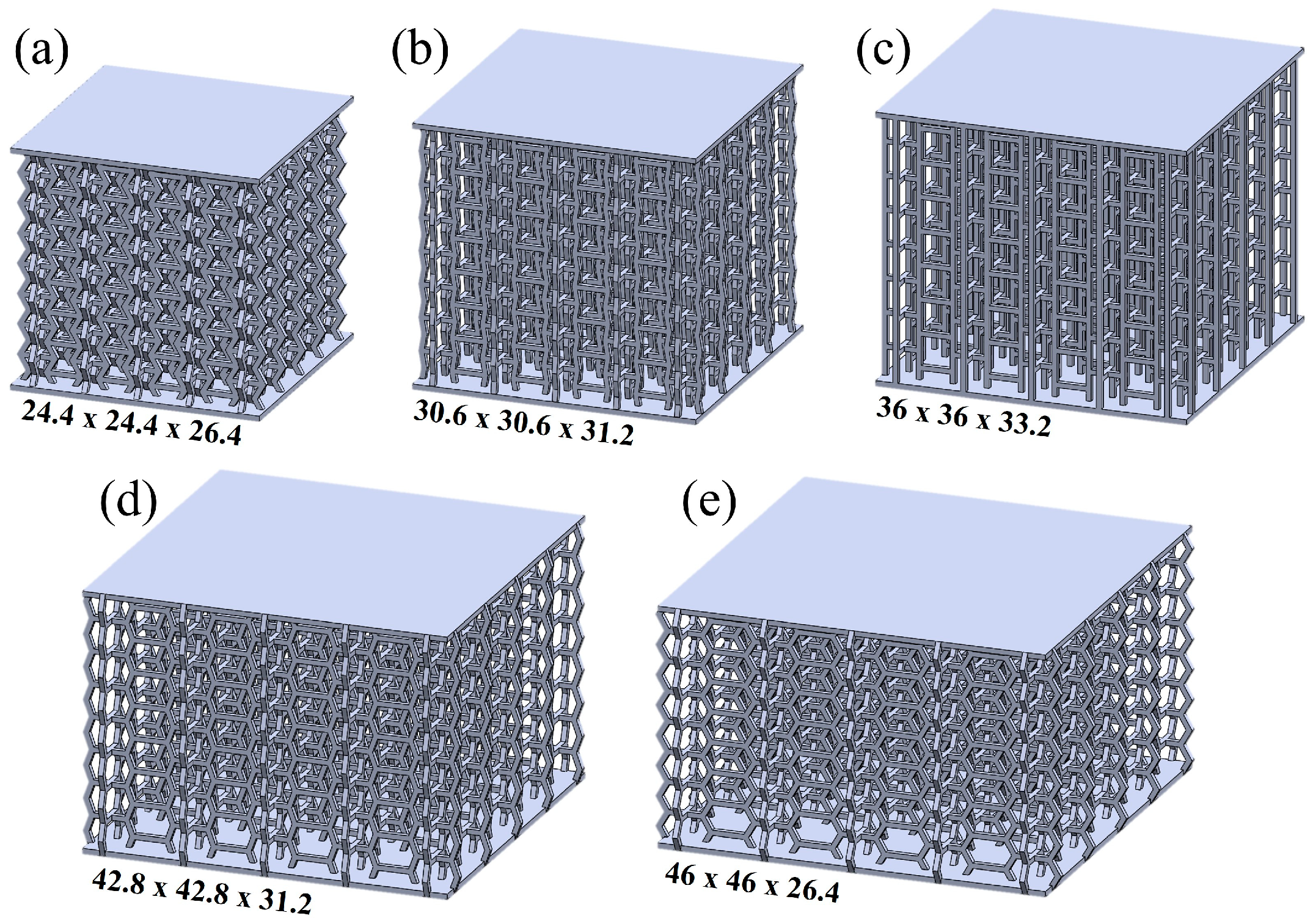
2.1. Scaffold Design and Selection
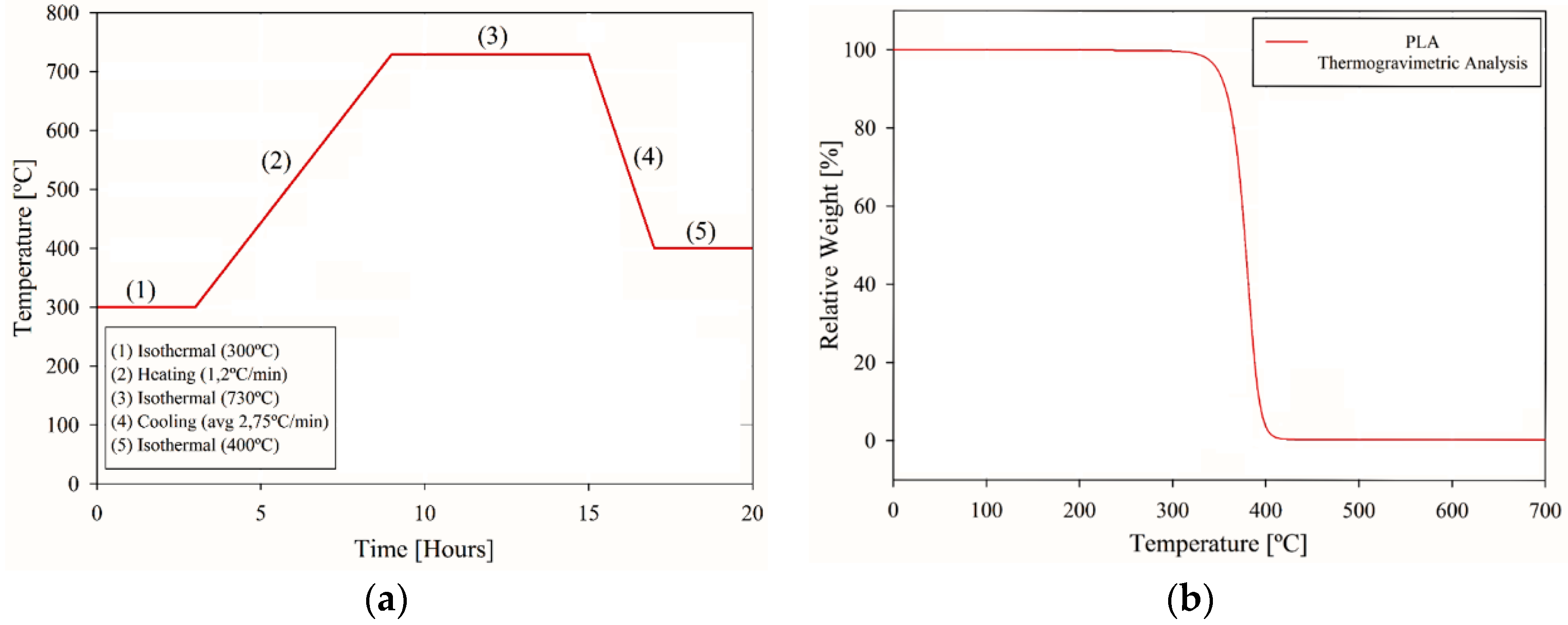
2.2. Ceramic Block Manufacturing
2.3. Vacuum Assisted Investment Casting
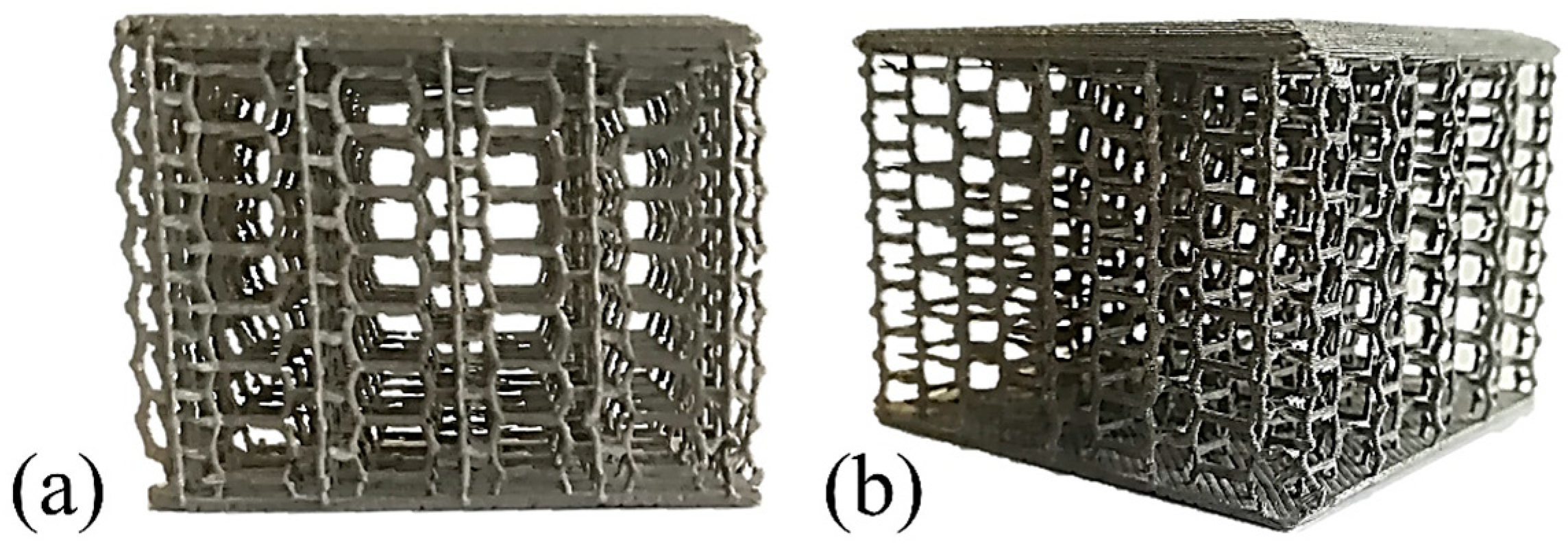
3. Results
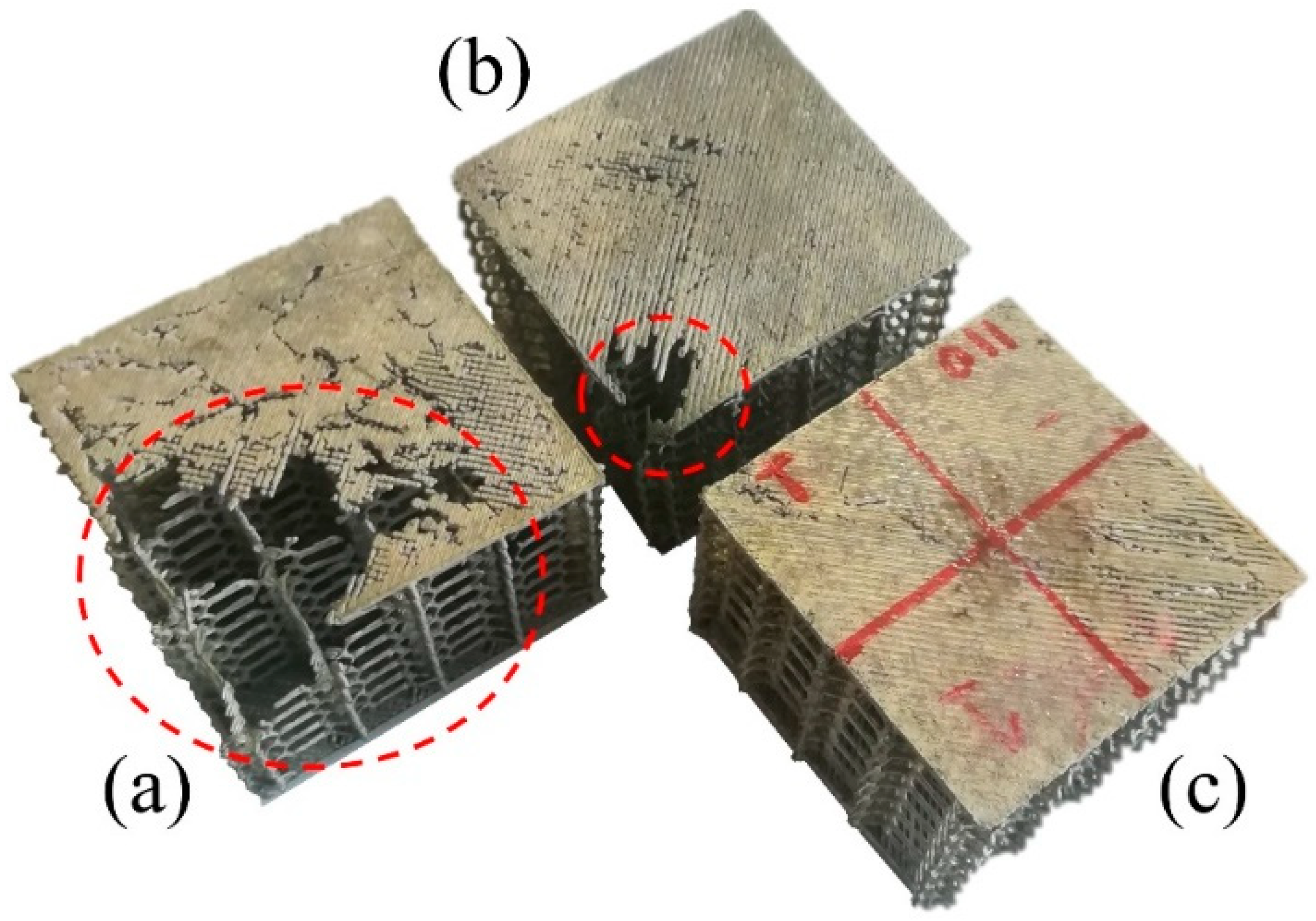
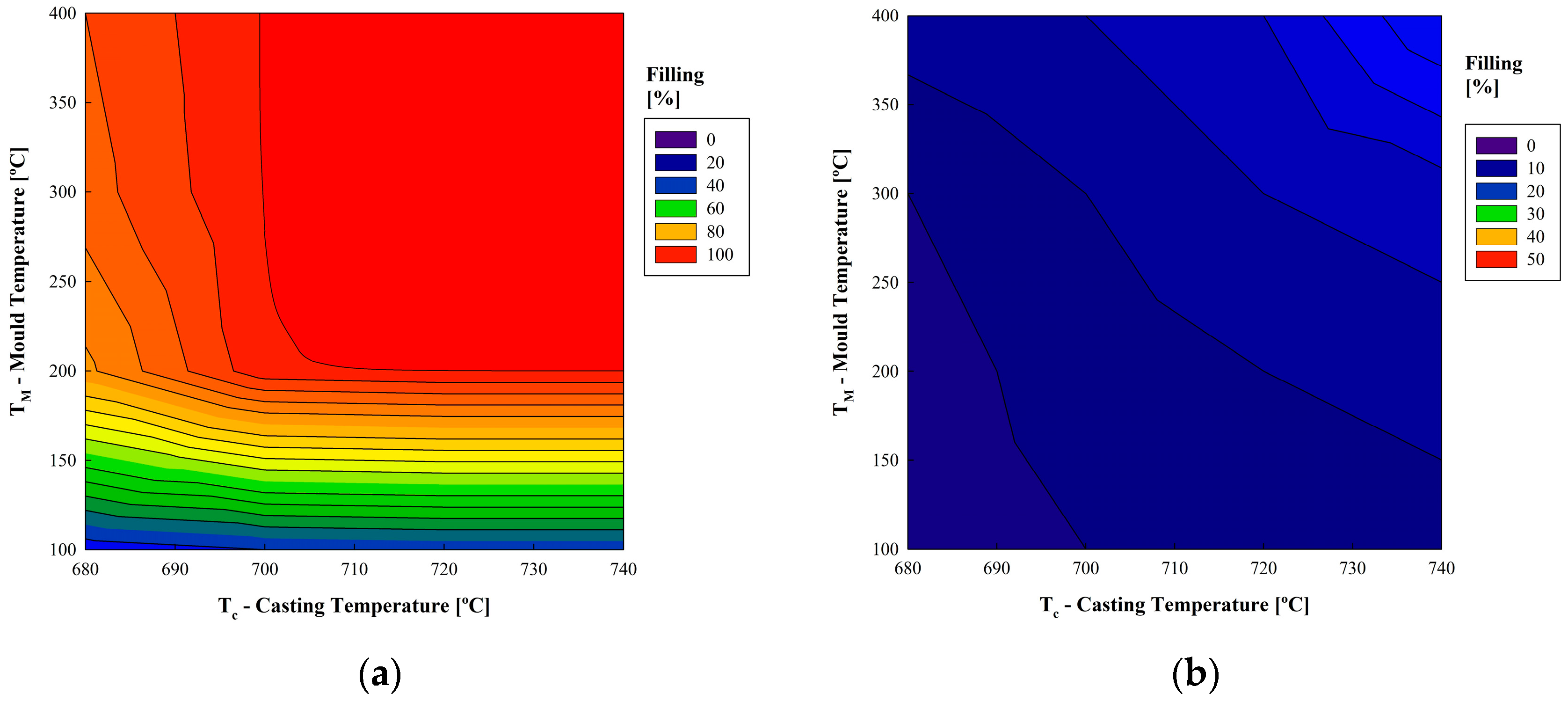
3.1. Influence of Mold and Casting Temperatures
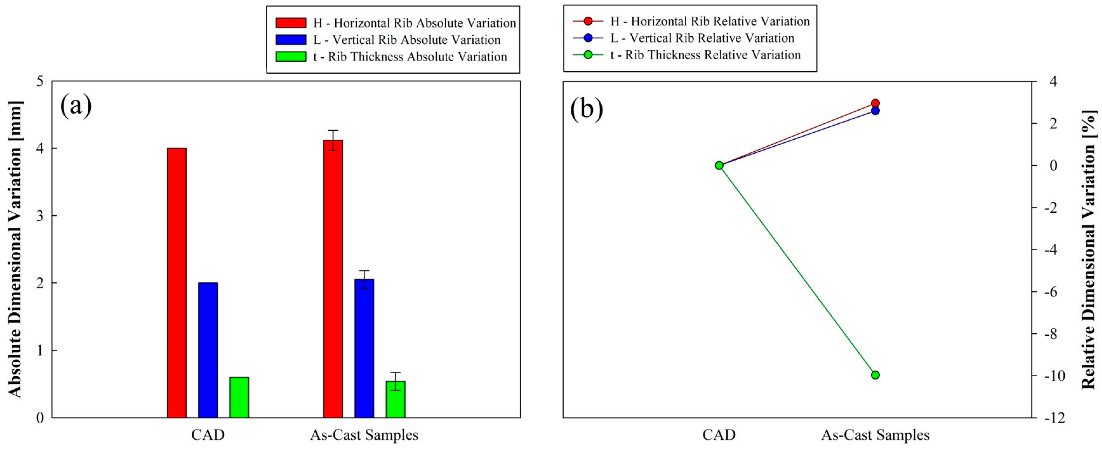
3.2. Dimensional Characterization of the Manufacturing Process
4. Conclusions
Author Contributions
Funding
Conflicts of Interest
References
- Gibson, L.J.; Ashby, M.F. Cellular Solids: Structure and Properties; Cambridge University Press: Cambridge, UK, 1999; ISBN 1-316-02542-X. [Google Scholar]
- Ashby, M.F.; Evans, T.; Fleck, N.A.; Hutchinson, J.; Wadley, H.; Gibson, L. Metal Foams: A Design Guide; Elsevier: Amsterdam, The Netherlands, 2000; ISBN 0-08-051146-5. [Google Scholar]
- Satyal, S.R.; Leshchinsky, B.; Han, J.; Neupane, M. Use of cellular confinement for improved railway performance on soft subgrades. Geotext. Geomembr. 2018, 46, 190–205. [Google Scholar] [CrossRef]
- Sol-Sánchez, M.; Moreno-Navarro, F.; Rubio-Gámez, M.C. The use of elastic elements in railway tracks: A state of the art review. Constr. Build. Mater. 2015, 75, 293–305. [Google Scholar] [CrossRef]
- Xie, S.; Zhou, H. Impact characteristics of a composite energy absorbing bearing structure for railway vehicles. Compos. Part B Eng. 2014, 67, 455–463. [Google Scholar] [CrossRef]
- Le Barbenchon, L.; Girardot, J.; Kopp, J.-B.; Viot, P. Multi-scale foam: 3D structure/compressive behaviour relationship of agglomerated cork. Materialia 2019, 5, 100219. [Google Scholar] [CrossRef]
- Xing, Y.; Yang, X.; Yang, J.; Sun, Y. A theoretical model of honeycomb material arresting system for aircrafts. Appl. Math. Model. 2017, 48, 316–337. [Google Scholar] [CrossRef]
- Yang, X.; Zhang, Z.; Xing, Y.; Yang, J.; Sun, Y. A new theoretical model of aircraft arresting system based on polymeric foam material. Aerosp. Sci. Technol. 2017, 66, 284–293. [Google Scholar] [CrossRef]
- Yan, Q.; Dong, H.; Su, J.; Han, J.; Song, B.; Wei, Q.; Shi, Y. A Review of 3D Printing Technology for Medical Applications. Engineering 2018, 4, 729–742. [Google Scholar] [CrossRef]
- Murr, L.E. Strategies for creating living, additively manufactured, open-cellular metal and alloy implants by promoting osseointegration, osteoinduction and vascularization: An overview. Recent Adv. Addit. Manuf. Met. Alloys 2019, 35, 231–241. [Google Scholar] [CrossRef]
- Carneiro, V.H.; Puga, H. Deformation behaviour of self-expanding magnesium stents based on auxetic chiral lattices. Ciênc. Tecnol. Mater. 2016, 28, 14–18. [Google Scholar] [CrossRef]
- Yang, D.-H.; Hur, B.-Y.; Yang, S.-R. Study on fabrication and foaming mechanism of Mg foam using CaCO3 as blowing agent. J. Alloys Compd. 2008, 461, 221–227. [Google Scholar] [CrossRef]
- Gnyloskurenko, S.V.; Koizumi, T.; Kita, K.; Nakamura, T. Aluminum Metallic Foams Made by Carbonate Foaming Agents. Resour. Process. 2013, 60, 5–12. [Google Scholar] [CrossRef][Green Version]
- Li, P.; Nguyen, N.V.; Hao, H. Dynamic compressive behaviour of Mg foams manufactured by the direct foaming process. Mater. Des. 2016, 89, 636–641. [Google Scholar] [CrossRef]
- Wang, N.; Maire, E.; Chen, X.; Adrien, J.; Li, Y.; Amani, Y.; Hu, L.; Cheng, Y. Compressive performance and deformation mechanism of the dynamic gas injection aluminum foams. Mater. Charact. 2019, 147, 11–20. [Google Scholar] [CrossRef]
- Heim, K.; García-Moreno, F.; Banhart, J. Particle size and fraction required to stabilise aluminium alloy foams created by gas injection. Scr. Mater. 2018, 153, 54–58. [Google Scholar] [CrossRef]
- Rajak, D.K.; Mahajan, N.N.; Das, S. Fabrication and investigation of influence of CaCO3 as foaming agent on Al-SiCp foam. Mater. Manuf. Process. 2019, 34, 379–384. [Google Scholar] [CrossRef]
- Jain, H.; Gupta, G.; Kumar, R.; Mondal, D.P. Microstructure and compressive deformation behavior of SS foam made through evaporation of urea as space holder. Mater. Chem. Phys. 2019, 223, 737–744. [Google Scholar] [CrossRef]
- Xie, B.; Fan, Y.Z.; Mu, T.Z.; Deng, B. Fabrication and energy absorption properties of titanium foam with CaCl2 as a space holder. Mater. Sci. Eng. A 2017, 708, 419–423. [Google Scholar] [CrossRef]
- Adamek, G.; Jakubowicz, J. Tantalum foam made with sucrose as a space holder. Int. J. Refract. Met. Hard Mater. 2015, 53, 51–55. [Google Scholar] [CrossRef]
- Yang, X.; Hu, Q.; Du, J.; Song, H.; Zou, T.; Sha, J.; He, C.; Zhao, N. Compression fatigue properties of open-cell aluminum foams fabricated by space-holder method. Int. J. Fatigue 2019, 121, 272–280. [Google Scholar] [CrossRef]
- Huang, S.M.; Nauman, E.A.; Stanciu, L.A. Investigation of porosity on mechanical properties, degradation and in-vitro cytotoxicity limit of Fe30Mn using space holder technique. Mater. Sci. Eng. C 2019, 99, 1048–1057. [Google Scholar] [CrossRef]
- Puga, H.; Carneiro, V.H.; Jesus, C.; Pereira, J.; Lopes, V. Influence of particle diameter in mechanical performance of Al expanded clay syntactic foams. Compos. Struct. 2018, 184, 698–703. [Google Scholar] [CrossRef]
- Szyniszewski, S.T.; Smith, B.H.; Hajjar, J.F.; Schafer, B.W.; Arwade, S.R. The mechanical properties and modeling of a sintered hollow sphere steel foam. Mater. Des. 2014, 54, 1083–1094. [Google Scholar] [CrossRef]
- Szlancsik, A.; Katona, B.; Bobor, K.; Májlinger, K.; Orbulov, I.N. Compressive behaviour of aluminium matrix syntactic foams reinforced by iron hollow spheres. Mater. Des. 2015, 83, 230–237. [Google Scholar] [CrossRef]
- Andersen, O.; Göhler, H.; Kostmann, C.; Quadbeck, P.; Diologent, F.; Colas, D.; Kieback, B. Powder metallurgically manufactured cellular metals from carat gold alloys for decorative applications. Met. Powder Rep. 2018, 73, 72–79. [Google Scholar] [CrossRef]
- Ma, Y.; Yang, X.; He, C.; Yang, K.; Xu, J.; Sha, J.; Shi, C.; Li, J.; Zhao, N. Fabrication of in-situ grown carbon nanotubes reinforced aluminum alloy matrix composite foams based on powder metallurgy method. Mater. Lett. 2018, 233, 351–354. [Google Scholar] [CrossRef]
- Kang, K.-J. Wire-woven cellular metals: The present and future. Prog. Mater. Sci. 2015, 69, 213–307. [Google Scholar] [CrossRef]
- Lee, M.-G.; Ko, G.-D.; Song, J.; Kang, K.-J. Compressive characteristics of a wire-woven cellular metal. Mater. Sci. Eng. A 2012, 539, 185–193. [Google Scholar] [CrossRef]
- Hu, J.; Du, Q.; Gao, J.; Kang, J.; Guo, B. Compressive mechanical behavior of multiple wire metal rubber. Mater. Des. 2018, 140, 231–240. [Google Scholar] [CrossRef]
- Osorio-Hernández, J.O.; Suarez, M.A.; Goodall, R.; Lara-Rodriguez, G.A.; Alfonso, I.; Figueroa, I.A. Manufacturing of open-cell Mg foams by replication process and mechanical properties. Mater. Des. 2014, 64, 136–141. [Google Scholar] [CrossRef]
- Matheson, K.E.; Cross, K.K.; Nowell, M.M.; Spear, A.D. A multiscale comparison of stochastic open-cell aluminum foam produced via conventional and additive-manufacturing routes. Mater. Sci. Eng. A 2017, 707, 181–192. [Google Scholar] [CrossRef]
- Feng, X.; Zhang, Z.; Cui, X.; Jin, G.; Zheng, W.; Liu, H. Additive manufactured closed-cell aluminum alloy foams via laser melting deposition process. Mater. Lett. 2018, 233, 126–129. [Google Scholar] [CrossRef]
- Pape, F.; Noelke, C.; Kaierle, S.; Haferkamp, H.; Gesing, T.M. Influence of Foaming Agents on Laser Based Manufacturing of Closed-cell Ti Foam. Procedia Mater. Sci. 2014, 4, 97–102. [Google Scholar] [CrossRef]
- Gao, Q.; Wang, L.; Zhou, Z.; Ma, Z.D.; Wang, C.; Wang, Y. Theoretical, numerical and experimental analysis of three-dimensional double-V honeycomb. Mater. Des. 2018, 139, 380–391. [Google Scholar] [CrossRef]
- Yang, L.; Cormier, D.; West, H.; Harrysson, O.; Knowlson, K. Non-stochastic Ti–6Al–4V foam structures with negative Poisson’s ratio. Mater. Sci. Eng. A 2012, 558, 579–585. [Google Scholar] [CrossRef]
- Murr, L.E. Open-cellular metal implant design and fabrication for biomechanical compatibility with bone using electron beam melting. J. Mech. Behav. Biomed. Mater. 2017, 76, 164–177. [Google Scholar] [CrossRef]
- Caiazzo, F.; Campanelli, S.L.; Cardaropoli, F.; Contuzzi, N.; Sergi, V.; Ludovico, A.D. Manufacturing and characterization of similar to foam steel components processed through selective laser melting. Int. J. Adv. Manuf. Technol. 2017, 92, 2121–2130. [Google Scholar] [CrossRef]
- De Pasquale, G.; Luceri, F.; Riccio, M. Experimental Characterization of SLM and EBM Cubic Lattice Structures for Lightweight Applications. Exp. Mech. 2019, 1–14. [Google Scholar] [CrossRef]
- Chang, K.; Gao, J.-T.; Wang, Z.; Guo, Z.-C. Manufacturing 3-D open-cell aluminum foam via infiltration casting in a super-gravity field. J. Mater. Process. Technol. 2018, 252, 705–710. [Google Scholar] [CrossRef]
- Bracconi, M.; Ambrosetti, M.; Okafor, O.; Sans, V.; Zhang, X.; Ou, X.; Da Fonte, C.P.; Fan, X.; Maestri, M.; Groppi, G.; et al. Investigation of pressure drop in 3D replicated open-cell foams: Coupling CFD with experimental data on additively manufactured foams. Chem. Eng. J. 2018. [Google Scholar] [CrossRef]
- Li, N.; Huang, S.; Zhang, G.; Qin, R.; Liu, W.; Xiong, H.; Shi, G.; Blackburn, J. Progress in additive manufacturing on new materials: A review. Recent Adv. Addit. Manuf. Met. Alloys 2019, 35, 242–269. [Google Scholar] [CrossRef]
- Pokharel, R.; Balogh, L.; Brown, D.W.; Clausen, B.; Gray, G.T.; Livescu, V.; Vogel, S.C.; Takajo, S. Signatures of the unique microstructure of additively manufactured steel observed via diffraction. Scr. Mater. 2018, 155, 16–20. [Google Scholar] [CrossRef]
- Zinovieva, O.; Zinoviev, A.; Ploshikhin, V. Three-dimensional modeling of the microstructure evolution during metal additive manufacturing. Comput. Mater. Sci. 2018, 141, 207–220. [Google Scholar] [CrossRef]
- Gorsse, S.; Hutchinson, C.; Gouné, M.; Banerjee, R. Additive manufacturing of metals: A brief review of the characteristic microstructures and properties of steels, Ti-6Al-4V and high-entropy alloys. Sci. Technol. Adv. Mater. 2017, 18, 584–610. [Google Scholar] [CrossRef] [PubMed]
- Yang, C.; Li, B.; Ren, M.; Fu, H. Micro precision casting based on investment casting for micro structures with high aspect ratio. Trans. Nonferrous Met. Soc. China 2009, 19, s521–s525. [Google Scholar] [CrossRef]
- Dong, X.; Zhu, X.; Ji, S. Effect of super vacuum assisted high pressure die casting on the repeatability of mechanical properties of Al-Si-Mg-Mn die-cast alloys. J. Mater. Process. Technol. 2019, 266, 105–113. [Google Scholar] [CrossRef]
- Yu, W.; Yuan, Z.; Guo, Z.; Xiong, S. Characterization of A390 aluminum alloy produced at different slow shot speeds using vacuum assisted high pressure die casting. Trans. Nonferrous Met. Soc. China 2017, 27, 2529–2538. [Google Scholar] [CrossRef]
- Dong, X.; Yang, H.; Zhu, X.; Ji, S. High strength and ductility aluminium alloy processed by high pressure die casting. J. Alloys Compd. 2019, 773, 86–96. [Google Scholar] [CrossRef]
- Viswanath, A.; Manu, M.V.; Savithri, S.; Pillai, U.T.S. Numerical simulation and experimental validation of free surface flows during low pressure casting process. J. Mater. Process. Technol. 2017, 244, 320–330. [Google Scholar] [CrossRef]
- Sanitas, A.; Bedel, M.; El Mansori, M. Experimental and numerical study of section restriction effects on filling behavior in low-pressure aluminum casting. J. Mater. Process. Technol. 2018, 254, 124–134. [Google Scholar] [CrossRef]
- Snelling, D.; Williams, C.; Druschitz, A. Mechanical and Material Properties of Castings produced via 3d printed molds. Addit. Manuf. 2019, 27, 199–207. [Google Scholar] [CrossRef]
- Shangguan, H.; Kang, J.; Deng, C.; Hu, Y.; Huang, T. 3D-printed shell-truss sand mold for aluminum castings. J. Mater. Process. Technol. 2017, 250, 247–253. [Google Scholar] [CrossRef]
- Upadhyay, M.; Sivarupan, T.; El Mansori, M. 3D printing for rapid sand casting—A review. J. Manuf. Process. 2017, 29, 211–220. [Google Scholar] [CrossRef]
- Sama, S.R.; Badamo, T.; Lynch, P.; Manogharan, G. Novel sprue designs in metal casting via 3D sand-printing. Addit. Manuf. 2019, 25, 563–578. [Google Scholar] [CrossRef]
- Sama, S.R.; Wang, J.; Manogharan, G. Non-conventional mold design for metal casting using 3D sand-printing. Adv. Manuf. Process. Res. 2018, 34, 765–775. [Google Scholar] [CrossRef]
- Xue, Y.; Wang, X.; Wang, W.; Zhong, X.; Han, F. Compressive property of Al-based auxetic lattice structures fabricated by 3-D printing combined with investment casting. Mater. Sci. Eng. A 2018, 722, 255–262. [Google Scholar] [CrossRef]
- Kang, J.; Ma, Q. The role and impact of 3D printing technologies in casting. China Foundry 2017, 14, 157–168. [Google Scholar] [CrossRef]
- Wang, D.; Dong, A.; Zhu, G.; Shu, D.; Sun, J.; Li, F.; Sun, B. Rapid casting of complex impeller based on 3D printing wax pattern and simulation optimization. Int. J. Adv. Manuf. Technol. 2019, 100, 2629–2635. [Google Scholar] [CrossRef]
- Kwon, Y.-D.; Lee, Z.-H. The effect of grain refining and oxide inclusion on the fluidity of Al–4.5Cu–0.6Mn and A356 alloys. Mater. Sci. Eng. A 2003, 360, 372–376. [Google Scholar] [CrossRef]
- Wankhede, D.M.; Narkhede, B.E.; Mahajan, S.K.; Choudhari, C.M. Influence of pouring temperature and external chills on mechanical properties of aluminum silicon alloy castings. Mater. Today Proc. 2018, 5, 17627–17635. [Google Scholar] [CrossRef]
- Eskin, D.G.; Al-Helal, K.; Tzanakis, I. Application of a plate sonotrode to ultrasonic degassing of aluminum melt: Acoustic measurements and feasibility study. J. Mater. Process. Technol. 2015, 222, 148–154. [Google Scholar] [CrossRef]
- Dong, Y.W.; Li, X.L.; Zhao, Q.; Yang, J.; Dao, M. Modeling of shrinkage during investment casting of thin-walled hollow turbine blades. J. Mater. Process. Technol. 2017, 244, 190–203. [Google Scholar] [CrossRef]
- Phetrattanarangsi, T.; Puncreobutr, C.; Khamkongkaeo, A.; Thongchai, C.; Sakkomolsri, B.; Kuimalee, S.; Kidkhunthod, P.; Chanlek, N.; Lohwongwatana, B. The behavior of gypsum-bonded investment in the gold jewelry casting process. Thermochim. Acta 2017, 657, 144–150. [Google Scholar] [CrossRef]
- Bayani, H.; Mirbagheri, S.M.H.; Barzegari, M.; Firoozi, S. Simulation of unconstrained solidification of A356 aluminum alloy on distribution of micro/macro shrinkage. J. Mater. Res. Technol. 2014, 3, 55–70. [Google Scholar] [CrossRef]
- Kumar Nayak, R.; Venugopal, S. Prediction of shrinkage allowance for tool design of aluminium alloy (A356) investment casting. Mater. Today Proc. 2018, 5, 24997–25005. [Google Scholar] [CrossRef]


| Horizontal Rib Length [mm] | Vertical Rib Length [mm] | Rib Thickness [mm] | Rib Angle [°] | Aspect Ratio (Length/Thickness) |
|---|---|---|---|---|
| 4 | 2 | 0.6 | −30 to 30 | 6.7 |
| Mold Temperatures TM [°C] | Casting Temperatures TC [°C] | Vacuum Pressure (If Used) [bar] |
|---|---|---|
| 100 to 400 (50 °C steps) | 680 to 740 (10 °C steps) | −1 |
© 2019 by the authors. Licensee MDPI, Basel, Switzerland. This article is an open access article distributed under the terms and conditions of the Creative Commons Attribution (CC BY) license (http://creativecommons.org/licenses/by/4.0/).
Share and Cite
Carneiro, V.H.; Puga, H.; Peixinho, N.; Meireles, J. Thin-Rib and High Aspect Ratio Non-Stochastic Scaffolds by Vacuum Assisted Investment Casting. J. Manuf. Mater. Process. 2019, 3, 34. https://doi.org/10.3390/jmmp3020034
Carneiro VH, Puga H, Peixinho N, Meireles J. Thin-Rib and High Aspect Ratio Non-Stochastic Scaffolds by Vacuum Assisted Investment Casting. Journal of Manufacturing and Materials Processing. 2019; 3(2):34. https://doi.org/10.3390/jmmp3020034
Chicago/Turabian StyleCarneiro, Vitor H., Hélder Puga, Nuno Peixinho, and José Meireles. 2019. "Thin-Rib and High Aspect Ratio Non-Stochastic Scaffolds by Vacuum Assisted Investment Casting" Journal of Manufacturing and Materials Processing 3, no. 2: 34. https://doi.org/10.3390/jmmp3020034
APA StyleCarneiro, V. H., Puga, H., Peixinho, N., & Meireles, J. (2019). Thin-Rib and High Aspect Ratio Non-Stochastic Scaffolds by Vacuum Assisted Investment Casting. Journal of Manufacturing and Materials Processing, 3(2), 34. https://doi.org/10.3390/jmmp3020034