Review

On Coating Techniques for Surface Protection: A Review

by
Behzad Fotovvati
1,*,
Navid Namdari
2 and
Amir Dehghanghadikolaei
3
1
Department of Mechanical Engineering, The University of Memphis, Memphis, TN 38152, USA
2
Mechanical, Industrial and Manufacturing Engineering Department, The University of Toledo, Toledo, OH 43606, USA
3
School of Mechanical, Industrial and Manufacturing Engineering, Oregon State University, Corvallis, OR 97331, USA
*
Author to whom correspondence should be addressed.
J. Manuf. Mater. Process. 2019, 3(1), 28; https://doi.org/10.3390/jmmp3010028
Submission received: 21 February 2019 / Revised: 10 March 2019 / Accepted: 18 March 2019 / Published: 25 March 2019

Abstract

:
A wide variety of coating methods and materials are available for different coating applications with a common purpose of protecting a part or structure exposed to mechanical or chemical damage. A benefit of this protective function is to decrease manufacturing cost since fabrication of new parts is not needed. Available coating materials include hard and stiff metallic alloys, ceramics, bio-glasses, polymers, and engineered plastic materials, giving designers a variety freedom of choices for durable protection. To date, numerous processes such as physical/chemical vapor deposition, micro-arc oxidation, sol–gel, thermal spraying, and electrodeposition processes have been introduced and investigated. Although each of these processes provides advantages, there are always drawbacks limiting their application. However, there are many solutions to overcome deficiencies of coating techniques by using the benefits of each process in a multi-method coating. In this article, these coating methods are categorized, and compared. By developing more advanced coating techniques and materials it is possible to enhance the qualities of protection in the future.

1. Introduction

Mechanical parts and structures are designed for specific applications. Prior to fabricating these parts, some extensive material selection constraints have to be met. These constraints include body materials, mechanical properties (e.g., tension, compression, yield, torsion, fatigue, bending, and creep), desired functionality (e.g., friction properties, hydrophobicity, wear resistance), thermal properties (e.g., thermal expansion and conductivity to transfer heat flux), electrical conductivity, dynamic load bearing (e.g., vibrations, high-speed rotation), and corrosion resistance. In addition, other parameters such as availability, cost of materials, safety, and toxicity of these materials must be considered. The latter category plays an important role in finalizing the material selection processes in advance to manufacturing mechanical parts and structures. For instance, silver is known to offer high electrical conductivity values, but fabricating a huge bulk of silver for electrical conductivity applications is too costly [1]. NiTi alloys are well-known for showing the shape memory effect (SME) and superelasticity (SE), which are useful in designing new actuators. Moreover, these alloys provide high biocompatibility as they are used as bone implants that could be combined with SME, SE, or both, to develop new biomedical devices for micro-surgeries inside the human body. However, the corrosion process of NiTi in physiological environments releases Ni ions as byproducts, which are a toxic and harmful category of materials for living organs [2]. Copper is a material with high thermal and electrical conductivity with many applications such as brazing advanced materials; however, it suffers from low stiffness and wear resistance. In the case of copper rotary cooling fins, the durability of the mechanical parts decreases significantly due to the high susceptibility of copper to wear mechanism [3]. To overcome these issues and to enhance material properties for specific applications, there have been different methods offered, such as heat treatment, alloying processes, and coatings. Among these solutions, coating processes have the highest portion of material enhancement since coating layers can reduce the cost and neglect scarcity of materials as the thickness of coating layers rarely pass micrometers. This means less material is needed to form coating layers on a bulk of substrate materials. Coatings can offer different properties such as corrosion/wear resistance, enhanced surface hardness, modified surface texture, thermal/electrical insulation, enhanced wettability, hydrophobicity, etc. [4].
Coating methods are available in a wide variety due to the enormous diversity of applications and needs in different fields. These processes consist of many different on-line/off-line parameters while giving way to many different outcomes in the form of material microstructure, effectiveness, suitability, and durability. However, coating methods are useful in specific applications according to the desired functionality among which corrosion and wear protection are the most important [5]. Mechanical properties of the materials decrease by corrosion process whereas the corrosion products are released in different forms that may cause a more extreme corrosive environment or harmful side effects in different applications [6]. Coating materials have deferent deposition mechanisms that needs to be investigated for the revelation of their pros and cons for the desired application. There are many processes available, but only a few are among the most effective and applicable, including physical vapor deposition (PVD), chemical vapor deposition (CVD), micro-arc oxidation (MAO), sol–gel, thermal spray, and polymer coatings. Each of these methods is suitable for different applications as they offer different deposition methods, different materials, second phases, different thicknesses, and densities. As a result, mechanical stability, corrosion properties, biocompatibility (for biomedical applications), and enhancement of material behavior for a specific type of coating have to be considered carefully [7]. Although coating processes are applied to provide the abovementioned benefits, they suffer from disadvantages that degrade their reliability. Of these adverse effects, negative thermal effects (e.g., distortion, crack, delamination, etc.), destructive effects of loose atmospheric protection (e.g., penetration of inclusions and contaminations into the substrate) and coating materials properties (e.g., melting point, availability in different forms of foils/powders/rods, biocompatibility, etc.,) are the most crucial ones to be considered.
Materials selection is the key parameter in having a successful coating as they provide all protection purposes. Many different materials, including metals, ceramics, and polymers, can be used to form a protective layer [8]. However, the diversity of coating processes and material properties may cause difficulties in choosing the best composition of the deposited layer. To overcome this issue, the most popular candidates such as Al, Ti, Hf, Zr, Ni, Co, Pt, MgO, ZrO2, Al2O3, Y2O3, BeO, PEEK, and PTFE must be considered while any probable new candidates should not be neglected. Although each of the feedstock materials offer corrosion or wear resistance properties, they possess different melting points, mechanical behavior, and chemical properties. Combined with their availability in different forms of powders, rods, plates, and wires for specific uses, these parameters keep the material selection in a narrower range. This review briefly covers common coating methods, materials, and their surface modification quality whereas there are plenty of other protection processes such as heat treatment, mechanical treatment, mechanical/chemical finishing, and polishing, which have not been covered in this review.

2. Reliable Coating Methods

Coating processes provide protection to a specific part or area of a structure exposed to harsh and corrosive environments in different fields ranging from aerospace and the automotive industry to tiny biomedical devices and implants inside the human body.

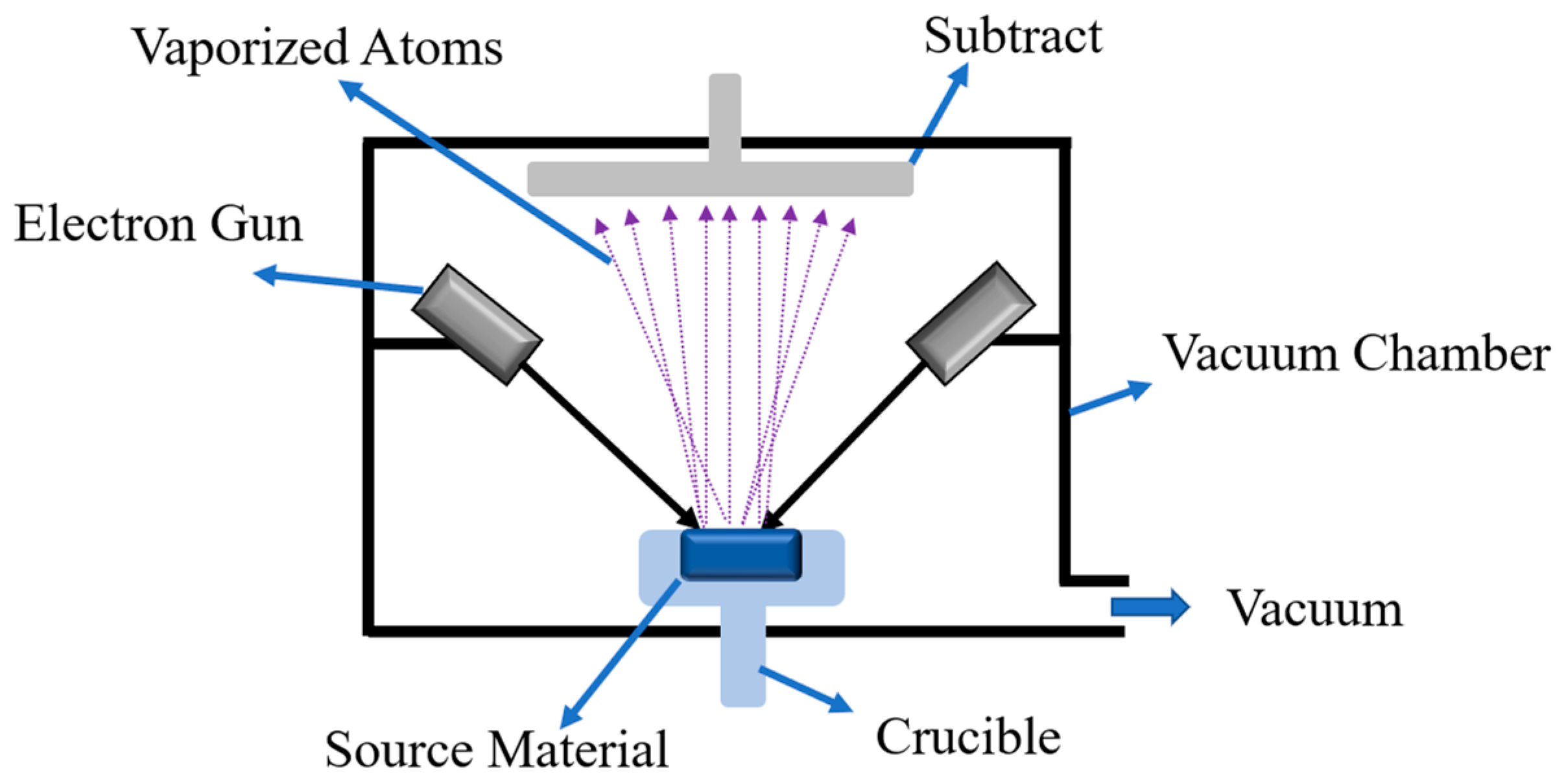
2.1. Physical Vapor Deposition (PVD) Coating

PVD process is famous for offering corrosion and wear resistance and thin protective films on the surface of the materials that are exposed to corrosive media, and its applications range from decorative objects to industrial parts [9]. The advantage of this method is that the mechanical, corrosion, and aesthetic properties of the coating layers could be adjusted on demand. In general, PVD is a process that takes place in a high vacuum and the solid/liquid materials transfer to a vapor phase followed by a metal vapor condensation, which creates a solid and dense film. The most known types of PVD are sputtering and evaporation. Since the coating layers created by PVD are thin in nature, there is always a need for multilayered coatings while the materials selection should be considered carefully. Apart from its decorative applications, many PVD-coated parts serve as components that undergo a high rate of wear that causes abrasion on the surface and removes the coating layer. This phenomenon reduces corrosion resistance properties of the parts and makes them more susceptible to a corrosive media. Figure 1 represents a schematic view of different types of electron beam PVD machines. In this method, the coating growth is dominated by a physical evaporation process. The thermal energy needed for evaporation may be supplied by different supply units, such as electron beam, heating wire, laser beam, molecular beam, etc. [10]. This thermal energy heats the atoms of the source material, which can be in the form of solid or liquid, to its evaporation point. The vaporized atoms travel a distance through the vacuum and deposit onto the substrate.
In different studies, the material composition of PVD coatings was investigated and they claimed that the base material of the coating significantly affected corrosion properties of the coated parts. As an example, Mathew et al. [11] investigated the corrosion properties of two different compositions of single-layered Ti-based (TiCxOy) and Zr-based (ZrCxOy) coating layers. They claimed that the Ti-based group provides better corrosion resistance compared to the Zr-based, one and in the Ti-based group, the highest corrosion enhancement was provided by samples with 0.55–0.79 fractions of oxygen in the coating composition. In other research related to the food industry by Damborenea et al. [10], the effect of the acidic environment of artificial casings in an acidic range of 1–3 pH was investigated. They reported that the PVD coating of TiN on the surface of stainless-steel equipment increased corrosion resistance and protected the equipment from corrosion failure for a significantly longer time. In addition to material selection for PVD coating compositions, many researchers investigated the effect of coating quality, porosity, and adhesion on different substrates such as stainless steel, Ti-based alloys, and ceramics [12,13,14,15]. In summary, PVD coating can be utilized in many applications such as aerospace, automotive, biomedical instruments, optics, and firearms. It provides the advantage of flexibility in using any organic and inorganic material as a deposition layer while the coating layer offers high hardness and corrosion resistance [16]. The PVD process for polymeric materials is challenging since the deposition leads to degradation of the polymer that reduces the molecular weight of the film. PVD has been used for polyethylene (PE), polyvinylidene fluoride (PVDF), and conductive π-conjugated polymers such as poly(2,5-thienylene) (PTh), and poly(pyridine-2-5-diyl) (PPy) [17,18].

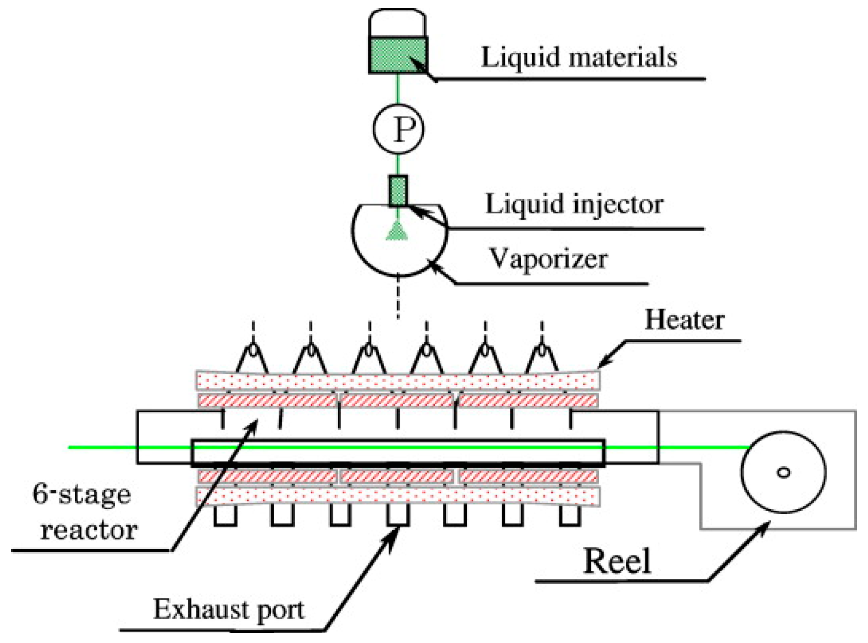
2.2. Chemical Vapor Deposition (CVD) Coating

Another type of vapor deposition is called CVD. This process undergoes a high vacuum and is widely used in the semiconductors industry providing a solid, high quality, and a high resistance coating layer on any substrate [19,20,21,22]. CVD can be used for mechanical parts in constant contact, which need protection against corrosion and wear. In this process, the substrate, known as a wafer, would be exposed to a set of volatile material precursors where a chemical reaction creates a deposition layer on the surface of the material. However, some byproducts of these chemical reactions, which are removed by constant airflow of the vacuum pump, can remain in the chamber. A schematic of the CVD setup is shown in Figure 2. The vaporized CVD materials are pumped from the right side and the heaters keep the temperature high enough to facilitate the chemical reaction between the substrate and vaporized materials.
CVD technique provides a wide selection of materials in different compositions and forms such as carbides, nitrides, oxynitrides, a composition of Si with O and Ge, carbon in forms of fluorocarbons, diamond, polymers, graphene, fibers/nanofibers/nanotubes, Ti, and W. In addition, these materials could be provided in different microstructures such as monocrystalline, polycrystalline, and amorphous [24,25]. Moreover, CVD of polymers has been shown to be a reliable process in applications such as biomedical device implants, circuit boards, and durable lubricious coatings [26]. CVD process performs in three different categories of atmospheric pressure CVD, low-pressure CVD, and ultra-high vacuum CVD, and the last two methods are the most common ones [27]. There are many other classifications related to the CVD process based on substrate heating, material properties, and types of plasma utilized in vaporizing the materials. These second-hand categories often include aerosol-assisted CVD, direct liquid injection CVD, plasma-enhanced CVD, microwave-plasma-assisted CVD, hybrid physical-chemical CVD, and photo-assisted CVD [28,29]. There are arguments on the advantages and disadvantages of CVD over PVD based on the applications. In the CVD process, the substrate is heated up to 900 ℃, which cannot be used for temperature-sensitive materials. PVD provides a solution for materials of this kind. On the other hand, CVD has the advantage of less waste of materials since only the heated area can be coated. In order to enhance this capability, computer-controlled lasers could be utilized to selectively heat the preferred areas [30,31].

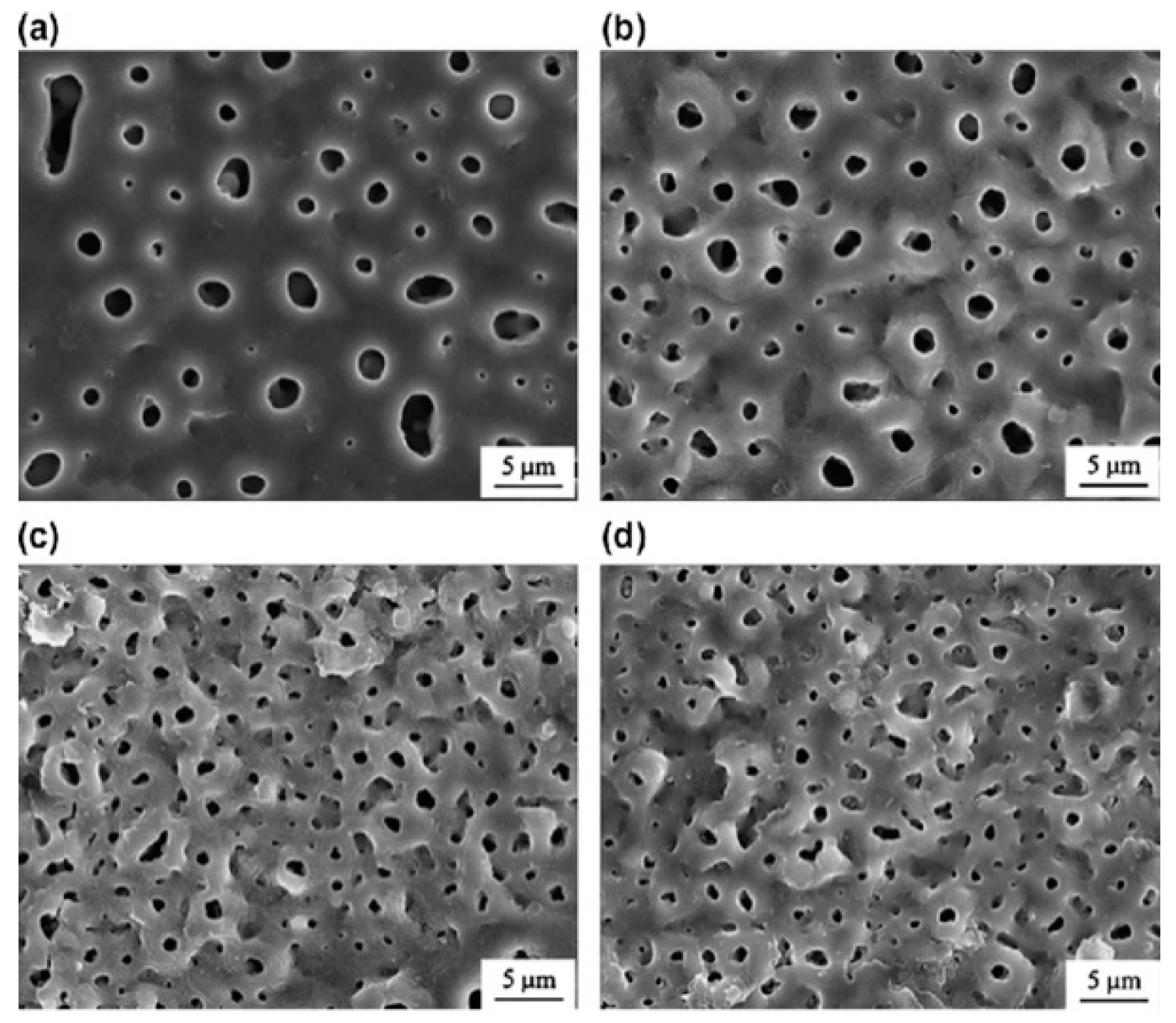
2.3. Micro-Arc Oxidation (MAO) Coating

MAO process is known as a flexible process of coating regarding the composition of coating layers. The schematic of the process is illustrated in Figure 3. In general, MAO utilizes a high voltage difference between anode and cathode to generate micro-arcs as plasma channels. When these arcs hit the substrate, they melt a portion of the surface, depending on the intensity of the micro-arcs. At the same time, plasma channels release their pressure, which assists the deposition of coating materials in the working electrolyte on the substrate surface. The existing oxygen inside the electrolyte causes a chemical reaction of oxidation and provides oxides deposited on the surface of the substrate materials. The versatility of this process lies in the flexibility of combining desired elements and compounds as a solute in the working electrolyte. To date, the materials most commonly coated with MAO are Al, Mg, Ti, and their alloys [32]. High corrosion resistance is the most important characteristic of a MAO-treated layer. In addition, being a porous structure, this coating layer provides high bone ingrowth while formed on biomedical implants and fixations [33].
Advantages of MAO can be a coating surface with high hardness and adherence properties while it has different scales of porosity throughout its structure. This type of multi-structural nature comes from the coating itself. Figure 4 illustrates a MAO-treated surface under different frequencies resulting in porous structures with different porosities. At the first steps of coating, a solid layer of metallic oxides covers the substrate called barrier inner layer. The porous structure is created on top of this layer during the next steps of coating with a reported thickness of up to 100 μ m [34]. This porous structure is the reason for increased surface adhesion in bio applications. The parameters affecting the coating quality are voltage, current density, electrolyte type, process time, pulsate current, and current type, i.e., AC or DC [35,36]. However, many researchers utilized different process parameter ranges and it has been claimed that in all the studies, corrosion properties of the coated samples improved while metallic ion release decreased significantly [37,38,39]. The only disadvantage of the MAO process might be its limitation in substrate materials that are mostly valve metals such as Al, Mg, Ti, Zr, Nb, and Ta [35].

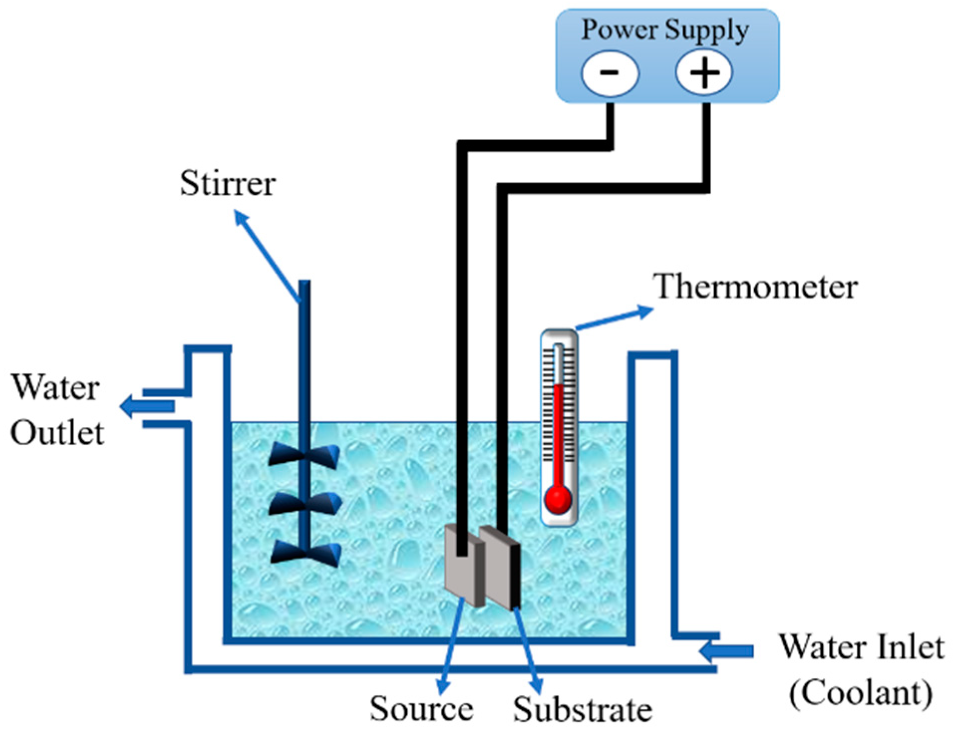
2.4. Electrodeposition Coating

Electrodeposition of materials is considered a type of protection utilizing the deposition of metallic ions on a substrate. In this process, a difference in potential between anode and cathode poles causes an ion transfer in the unit cell. After a while, a coating layer forms on the submerged sample by receiving ions from the other electrode. Extensive studies have been done on popular electrodeposition materials. The common group of metals that have been intensively studied includes, but is not limited to, Ni-P, Ni-P/Sn, Ni-P-W, Ag/Pd, Cu/Ag, Cu/Ni, Co/Ag, and Co/Pt [41,42,43]. According to these studies, the electrodeposited coatings significantly enhance the corrosion properties of the substrate. Moreover, this technique has been shown to be promising in producing superhydrophobic polymeric coatings such as polythiophene [44]. In general, electrodeposition is categorized into two processes known as electrolytic deposition (ELD) and electrophoretic deposition (EPD), which are discussed more in the following sections.

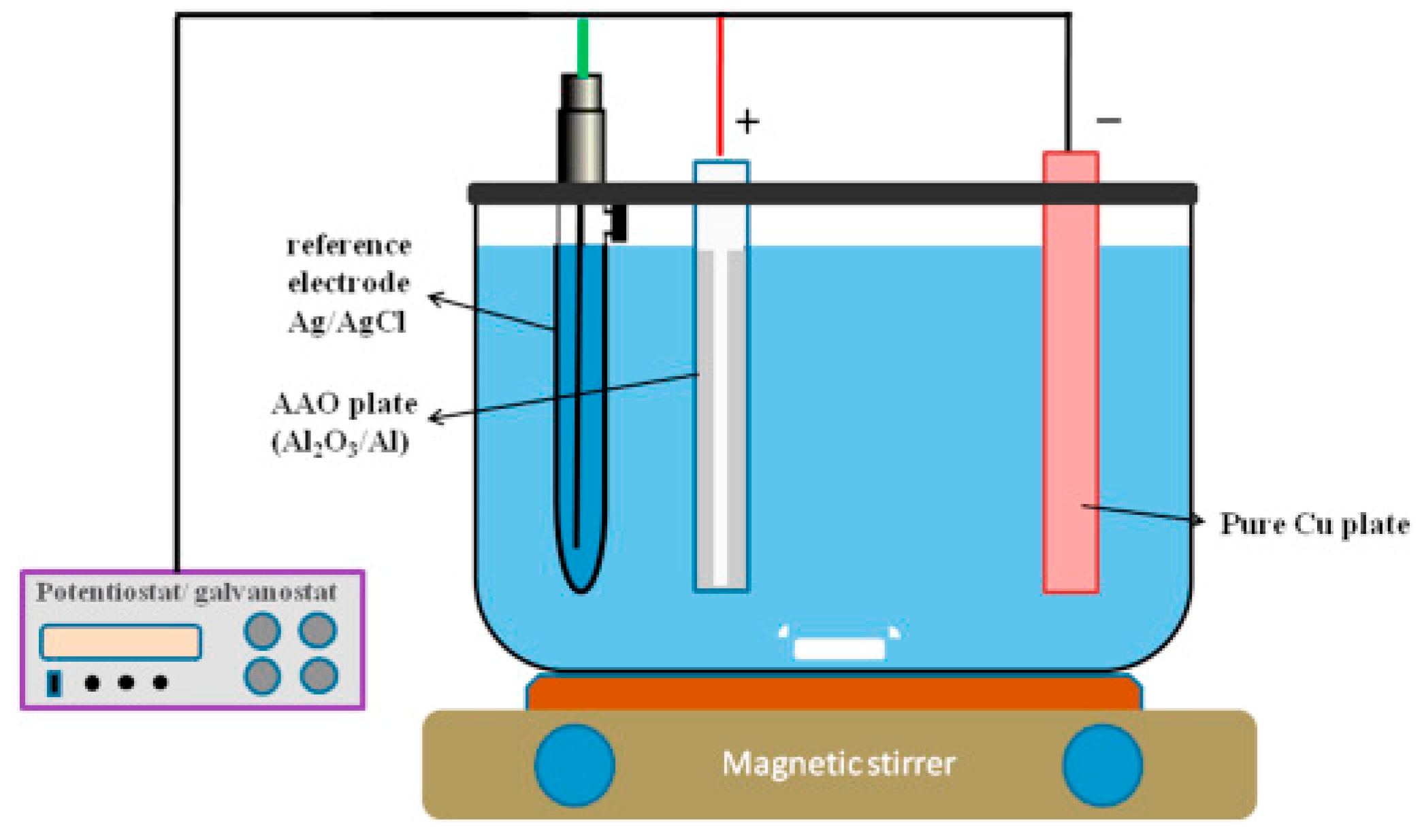
2.4.1. Electrolytic Deposition (ELD) Coating

ELD is an electrochemical process employed to form a dense metallic coating with a uniform thickness distribution on conductive substrates. Substrate and deposition materials are selected as cathode and anode while placed inside an electrochemical unit cell. Figure 5 illustrates a general overview of the process. By applying a potential difference between anode and cathode poles, metallic ions move toward working electrolyte and from there toward the substrate. The deposition phase requires super-saturation of electrolyte, which occurs due to charging current in the circuit. In this technique, the concentration of metallic ions of electrolyte remains constant during the coating process [45]. Although this method is mostly used for decorative and low-corrosion/wear applications, there have been reports of development of other applications such as optics, electronics, biomedical, high-temperature, and solid-oxide fuel cells [46,47]. By further increasing the potential difference in electrolytic unit cells, ceramic materials can be deposited on metallic substrates that is more similar to the MAO process. Tian et al. [48] deposited Ni-Co-Al2O3 on steel pipes and reported a notable enhancement of corrosion of substrate exposed to oil sand slurry. Yang et al. [49] deposited Ni-Co-SiC on carbon steel pipes exposed to oil sand slurry and reported significant corrosion and erosion-enhanced corrosion resistance. The same results were reported by Fayomi et al. [50] on a Zn-Ni-Al2O3-coated mild steel substrate. In addition, Redondo et al. [51] deposited a corrosion resistant polypyrrole (PPy) coating on a copper substrate from a dihydrogen phosphate solution.

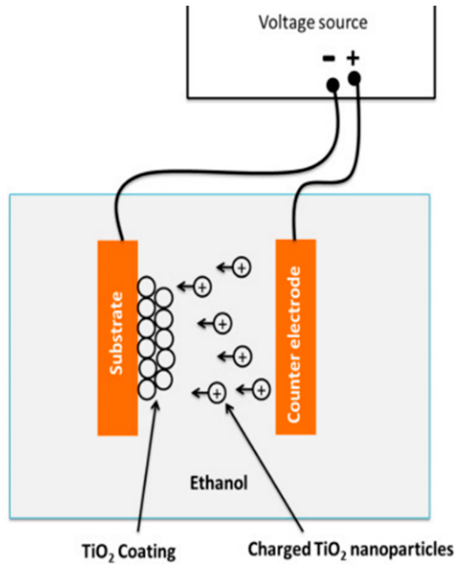
2.4.2. Electrophoretic Deposition (EPD) Coating

EPD is another form of electrodeposition that provides thicker coating layers with a colloidal nature. Using an electric field in a unit cell, similar to that of ELD, thin films form on substrates by coagulation of colloidal particles. EPD is a multi-phase technique, in which:
  • External electric field forces suspended particles in electrolyte toward one electrode called electrophoresis.
  • The moving particles gather in one electrode and form a larger coagulated particle.
  • The larger particles deposit on the surface of the electrode, which is a to-be-coated substrate.
Finally, a thick coating layer will be created on the substrate having a powder-shaped structure. Figure 6 represents a schematic of the working mechanism of the EPD process. Densification processes (e.g., furnace curing, light curing, sintering, etc.,) are recommended to increase the quality of the protective layer. Up to now, numerous applications have been introduced for EPD that include coating, selective deposition, graded material deposition, porous structure deposition, and biomedical applications [53,54]. The materials used in EPD are commonly borides, carbides, oxides, phosphates, and metals [53,55]. Castro et al. [56] reported fabricating corrosion resistant coatings by sol–gel and EPD on stainless-steel AISI 304 and reported two and four times increases in corrosion resistance for each of these processes, respectively. In another study by Gebhart et al. [57], an AISI 316 L stainless steel was coated with chitosan for biomedical applications. They reported positive effects of this coating on corrosion behavior of the substrate. They also asserted that the applied electric field in EPD is the key factor in controlling coating features, such as hydrophobicity, thickness, and structure. TC4 Ti-alloy orthopedic implants were coated by graphene by Chen et al. [58]. They reported that the graphene-coated artificial joint implants show a considerable increase in life span. They found that the reason any corrosion on substrates occurred was micro-cracks in coating surfaces. Fei et al. [59] studied the wear resistance of EPD coatings and successfully deposited SiC particles on paper-based friction materials and achieved an excellent wear enhancement of this material. Table 1 summarizes ELD and EPD processes regarding their characteristics and components.

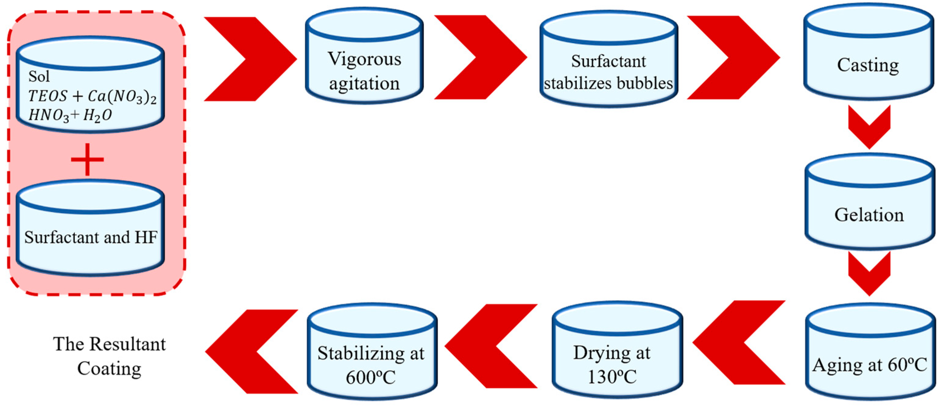
2.5. Sol–gel Coating

Sol–gel coating is one of the most successful coating processes of biomedical devices. The wide range of investigations on this process and its applications can ease the setup and performance of experiments while keeping the outcomes reliable [62]. On the other hand, sol–gel is capable of enhancing previously existing coating layers from corrosion and ion release point of view. Due to its liquid-permeating nature, sol–gel can easily seal porous coating structures or damaged layers. Calcium phosphorous (CaP) precursors dissolved in ethanol/distilled water are used to make the solution called as Sol. In order to make a gel phase out of the solution, the prepared mixture undergoes heating at different temperatures to facilitate the aqueous portion of the solution and increase the viscosity to the desired level. This phase, which transforms it from a liquid solution to a gel phase, is where sol–gel gets its name. After preparation, the parts or devices are dipped in the sol–gel medium at a constant and controlled speed. This process may be repeated to achieve a multilayered coating or thicker coating of the same material. In addition, the coated samples can be baked to dry out faster or to provide intentional dehydrating cracks on the surface of the coating layer for next processing steps. Figure 7 represents a schematic of an example of a sol–gel coating process.
Advantages of the sol–gel process include high adhesion of the coating layer, ability to coat complex geometries, flexibility in the composition of the coating layer, and lower cost than other similar coating processes. Additionally, there is no need to have a conductive material as a substrate as there is no extreme heating or vacuum applied to the parts meaning that the substrate will be virtually untouched during the coating process. Sol–gel coating is done in different forms such as dip-coating, spraying, and spinning [63,64]. Figure 8 shows a sol–gel deposited coating layer with a rough and porous microstructure. One disadvantage of this process could be that a constant speed of dipping and withdrawing is needed to maintain a uniform thickness of coating throughout the substrate surface. There is also always a possibility of coating failure during heat treatment on multilayered coating structures. Sol–gel coating for industrial applications is considered a slow process and is not cost effective in high production rates [65]. All these being said, the sol–gel process performs well when it comes to protecting a substrate against corrosion and decreasing ion release, as reported in many scientific studies [66,67]. Moreover, in a study by Faustini, et al. [68], models were proposed in order to explain and predict sol–gel behavior and the effect of dipping/withdrawing steps on the final quality of the coating layer. Likewise, many other studies investigated and proposed continuum-based/numerical models that could be implemented in predicting sol–gel mechanisms during the process and characteristics of the coating layers [69,70,71,72,73]. Hybrid network materials were generated using sol–gel process when either organic moieties or polymeric categories chemically bonded to an inorganic component. The chemical bond between the organic and inorganic network can be addressed through introducing functional groups into the polymeric part by silane, silanol, etc., using pre-introduced functional groups in the polymer, and exploiting alkoxysilanes precursors. Poly(dimethylsiloxane) (PDMS), poly(ether ketone) (PEK), and polycarbonate are among numerous polymeric materials that have been used in the sol–gel process [74,75,76,77].

2.6. Thermal Spray Coating

Thermal spray coating is a general term for a series of processes that utilize a plasma, electric, or chemical combustion heat source to melt a set of designed materials and spray the melt on the surface in order to produce a protective layer. These are reliable types of corrosion- and wear-resistant coatings. In this process, a heat source, which is mostly provided by chemical combustion or plasma discharge, heats up the materials to a molten or semi-solid phase and sprays them on the substrate with a high speed of a jet. The thickness achieved in thermal spray coating techniques can range from 20 μ m to several millimeters which is significantly higher than the thickness offered by electroplating, CVD, or PVD processes [79]. In addition, the materials that can be used as feedstock of thermal spray coatings range from refractory metals and metallic alloys to ceramics, plastics, and composites and can easily cover a relatively high surface area of a substrate [79]. Thermal spray coatings are categorized into different types based on their characteristics and process specifications. The most popular categories are plasma, detonation, warm/cold, high-velocity air fuel (HVAF), high-velocity oxyfuel (HVOF), flame, and wire arc spraying [80,81].

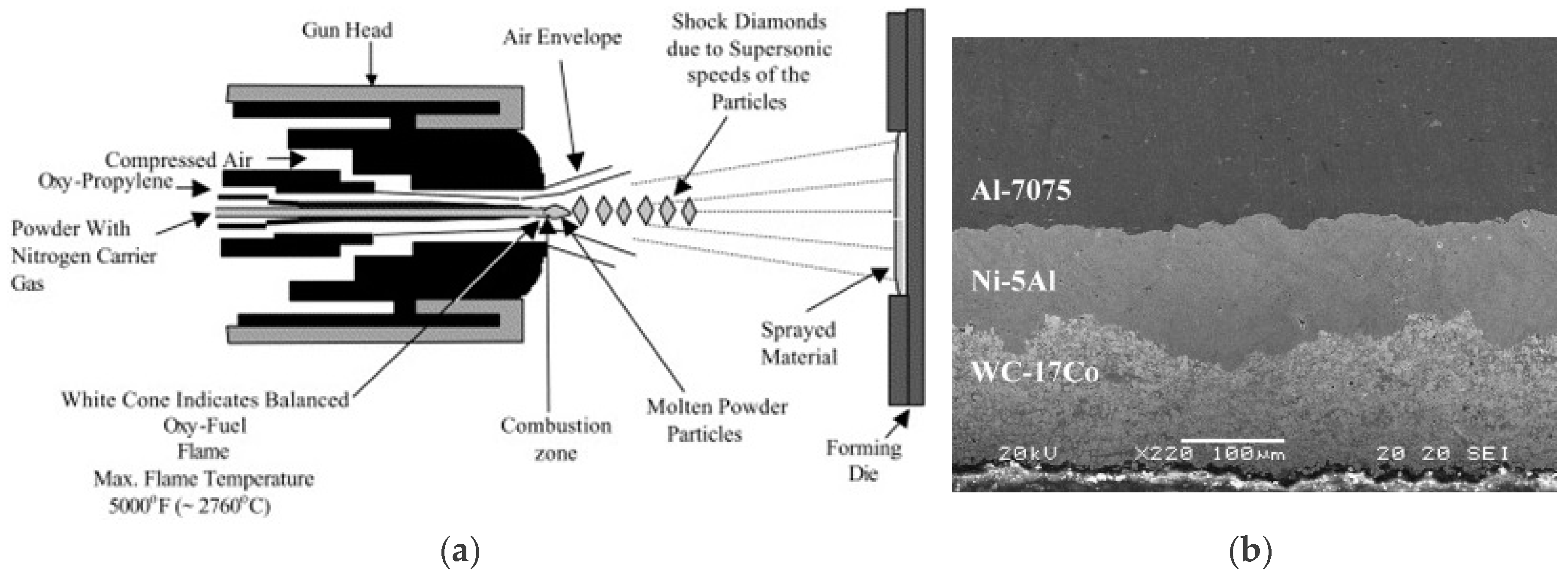
2.6.1. High-Velocity Oxy-Fuel Coating (HVOF)

Figure 9a represents an HVOF coating process in a schematic format. A mix of fuel, such as acetylene, propane, methane, hydrogen, or natural gas, and oxygen in gas or liquid phase undergo continuous combustion in a designed combustion chamber to provide a high-pressure steam of hot gas. The combustion chamber releases the combustion products into a nozzle to create a spray with a speed of more than 1000 m/s [82]. After combustion, coating materials in powder form are injected inside this hot jet stream to get partially melted accelerated while they are leaving the nozzle tip. The hot jet pushes the semisolid particles against the substrate and creates a coating layer with varying thicknesses up to several millimeters. The advantage of this process is that the coating layer has a high density and adheres to the substrate well, while it is able to utilize coating materials such as hydroxyapatite (HA), W, Cr, Al, Zr, and their oxides/carbides or polymeric materials such as nylon 11/silica nanocomposites to deposit corrosion- and wear-resistant layers [83,84]. Figure 9b represents a multilayer coating provided by HVOF. The coating layer could be performed on non-conductive materials such as polymers and ceramics that are able to undergo high velocity and temperature of the jet stream and the particle [85]. To date, many researchers have investigated corrosion and wear resistance of HVOF coatings in various applications and corrosive environments. Based on these studies, coating layers made by this technique served well and improved corrosion-wear properties of substrates [86,87,88]. A summary of these studies is listed in Table 2.

2.6.2. Plasma Spray Coating

Figure 10 illustrates a schematic view of a plasma spray coating setup. This process can be done under vacuum or atmospheric conditions. In this process, a plasma gun provides a high-temperature DC/induction plasma (up to 10000 K), which can easily melt refractory metals, ceramics, and polymers. The materials used in the stabilization of plasma can be gas, water, or a mixture of these two, known as hybrid plasma. The materials to be deposited are fed into this hot plasma stream and the high temperature melts the feedstock. Due to the high speed of plasma at the tip of a converging nozzle, the molten droplets are deposited instantly on the substrate against the coating setup. The flexibility of this process facilitates the utilization of different types of feedstock such as powder, slurry, suspensions, and liquids [91]. The resulting coating layer has a high corrosion and wear resistance and it is able to adhere to the substrate due to surface tension and high temperature. A significant corrosion- and wear-resistance enhancement was reported in many studies on different materials such as chromium oxide and NiCr alloys [92,93]. Plasma sprayed coating of polymers, especially PEEK, have been implemented for corrosion protection of metal substrates (nylon, PVDF), antistick coatings of papers and rollers, plastic moldings, wear-resistant coatings, moisture protection materials, and electrical barrier coatings [94]. On the other hand, vacuum plasma spraying is a low-temperature process and is mostly used for materials that cannot perform reactions in atmospheric pressure to modify the surface of the substrate. The most popular application of vacuum plasma spraying is the surface modification of engineering polymers and plastics, rubbers, metals, and fibers [95]. In this process, a material can go through cross-linking, friction decrease, adherence increase, etc. [95,96,97].

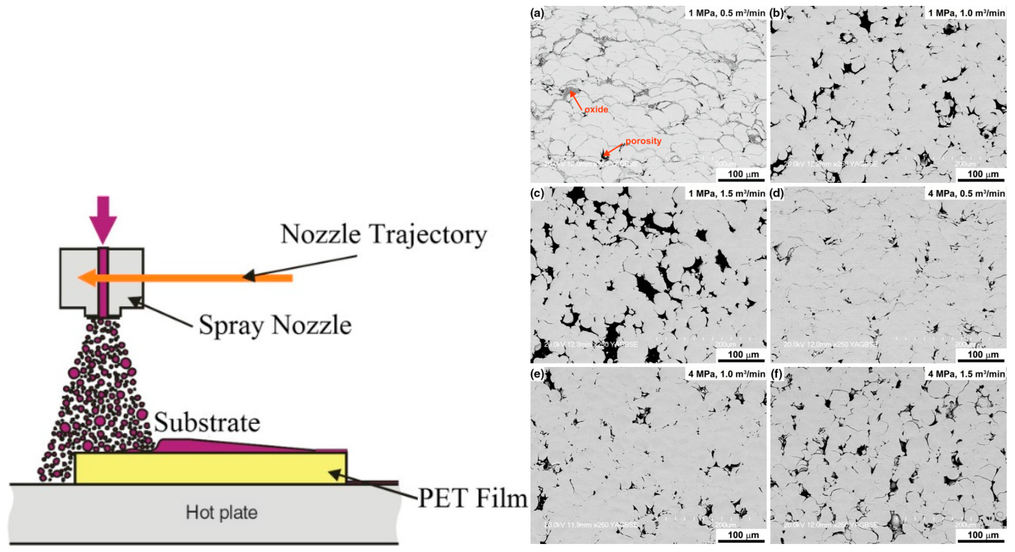
2.6.3. Cold Spray Coating

Cold spray coating is a technique that relies on impact and solid mechanics of particles. Unlike HVOF and plasma spray coating methods, this process does not utilize a heat source to perform coating on substrates. The general working mechanism of cold spray coating depends on particle size, the temperature of the target, material properties of coating particles, and a critical velocity [99]. Powder materials are fed to a stream of high-velocity mediums (helium and nitrogen) to achieve the desired kinetic energy. After particle-substrate impacts take place, this energy deforms the particles and bond them to the substrate. Another mechanism of this process can be penetration of the particles inside the substrate. Using a high flow rate of accelerated particles, the surface is coated with desired materials. The most-used powder materials consist of a wide range of plastics, metals, ceramics, composites, and metallic alloys [100,101]. In addition, the most-studied substrate materials include soft metals such as Al and Cu, while in literature, the coating of some hard materials such as W and Ti has been reported [102,103]. In some studies, the temperature of the accelerating medium has been increased in order to enhance process efficiency [104]. Although this process is simple and cheap compared to the other thermal spray methods, the operation range is very limited. Figure 11 shows SEM micrographs of cold spray-treated surfaces and a schematic view of cold spray coating process.

2.6.4. Warm Spray Coating

Figure 12 (left) shows a schematic representation of the warm spray coating method. As stated about cold spray coating, low working temperature decreases efficiency and reliability of thermal spray coating methods. However, high temperatures melt feedstock and introduce new chemical reactions, which may cause oxidation or change of properties due to extreme heating of particles and substrates. In order to overcome this problem, a new technique was introduced as a warm spray coating. This is a modification of HVOF coating that enjoys reduced temperature in the combustion chamber by introducing nitrogen to the fluid mixture. As a result, this method is categorized somewhere between cold spray coating and HVOF coating and provides a high efficiency of the coating process [107]. However, as reported in the literature, the achieved coating layer contains many impurities relative to the other two processes due to low temperature and existence of oxygen in the accelerating stream. These porosities and oxide phases are illustrated in Figure 12 (right). Advantages of using this process rise in the coating of materials, which are sensitive to oxidization in high temperatures or the materials that cannot withstand high working temperatures such as bio-metal-glasses, Ti and its alloys, engineering plastics, and polymers such as PEEK [108,109]. Cold/warm spray coatings are not used for extremely harsh environments, however many research studies investigated corrosion properties of this type of coating on different materials such as Ti, bio-metal-glasses, WC-Co cermet, etc., under different corrosion conditions and they claimed an enhancement in corrosion resistance of substrates [110,111].

2.6.5. Arc Wire Spray Coating

Another type of thermal spray coating technique is called arc wire spray coating (Figure 13a). In this process, two consumable metallic wires, which are charged with a DC supply, generate an arc between them resulting in a melting process of the feeding wires. The products of this melting process are then pumped out of a converging nozzle tip toward the target with the supplied pressure of compressed gas. Although the flexibility of this process allows for the use of many metallic alloys as coating layers, this process is limited to conductive wires and materials. In order to solve this issue, a modified version of arc wire plasma was introduced having one consumable wire, which makes an arc with a non-consumable metallic cathode [112]. The remaining steps of the process are the same as the original version. This method is well-known for applications of an internal surface coating such as engine blocks, etc., that offers a lighter metal as the whole block while the internal surfaces are coated with a wear- and corrosion-resistant metallic alloy. This flexibility can significantly reduce production cost. Almost all of the conductive materials such as Al, Zn, Mo, Ni, and other metallic alloys such as Ni and Ti alloys can be used as feedstock in this process [79,113]. In addition, utilization of cored wires is reported in the literature [114]. Figure 13b represents the microstructure of an arc wire spray-coated substrate. To this point, many of the popular thermal spray coating techniques have been introduced. However, there is no doubt that other processes could be investigated regarding their working mechanisms, coating efficiency, coating quality, speed of process, and ease of applications.

3. Summary

In order to have a successful coating deposition on a substrate, there are several affecting parameters including deposition materials, substrate materials, feedstock form (powder, wire, rods, precursors, etc.), and deposition methods. However, the deposition processes are the most important ones as they deal with chemical alteration of materials and alloying of composition elements in the coating layer. In addition, based on the characteristics of different feedstock and substrate materials, one can easily choose the best option for deposition. The processes that are the most successful and the most investigated deposition means are physical/chemical vapor deposition (PVD/CVD), micro-arc oxidation (MAO), electrodeposition (i.e., electrolytic deposition (ELD) and electrophoretic deposition (EPD)), sol–gel, and different types of thermal spraying processes (i.e., HVOF, plasma, cold, warm, and arc wire spraying). The mentioned processes utilize different mechanisms in order to deposit specific types of materials on substrates making the material selection important in order to have the highest efficiency of the coating. Some of the processes use thermal sources to change the state of feedstock to liquids and semisolids in forms of particles, droplets, and clusters. Some others use the difference between electrochemical charges between poles and some deposit materials without chemical change of state. Depending on the substrate materials, feedstock, and means of deposition, the coating layers are different in thickness, microstructure, and functionality. In addition, some processes are specific to metallic feedstocks, which are conductive, while the rest can deposit polymers, ceramics, and metallic alloys regardless of their physical properties.
In summary, the thermal processes, such as various types of thermal spray coating, implement high temperatures and high speed of plasma jets in order to have a higher material deposition rate. In these methods, the high temperatures and high-speed jets allow feedstock deposition and eliminate the adverse effects of high melting point on ceramics and superalloys. The obtained coating thicknesses, in these cases, are high (up to several hundred microns). However, the coating microstructure consists of oxide and carbide inclusions and provides porosity, depending on process parameters. In the vaporization-based processes, the deposited coating layer is a thin film with high corrosion/wear-resistance mostly used in tool coating and protection of sliding components of machines. The coating achieved in these types is a thin solid film with low porosity and high adherence to the substrate. Micro-arc oxidation is a high-voltage version of anodization, which is mostly implemented on biomaterials for bone implant and biomedical device applications. In addition, valve metals (Al, Ti, Zr, Hf, V, Nb) have been extensively used as substrates as well. The coating structured by MAO offers high substrate/coating adhesion with a porous structure that is crucial for biomaterial coating as the bone ingrowth increases. The porous microstructure also enhances the corrosion resistance and facilitates the engineering calculations on the lifetime of the implants, either degrading fast or staying for a longer time. Sol–gel is another type of material deposition that is significantly flexible in feedstock composition, and as the process utilizes aqueous solutions as particle carriers, the complexity of geometry does not affect the coating quality. In addition, sol–gel-deposited layers are a reliable sealant for porous substrates and coatings in order to increase their corrosion resistance. Although sol–gel offers high flexibility and capability in coating purposes, the process is relatively slow and increases the production time. Electrochemical processes are another type of aqueous deposition methods utilizing the difference between electrochemical charges of anode and cathode poles of a chemical unit cell. The flexibility in the coating composition and a wide variety of substrates used in this method make it a reliable deposition process. However, this process suffers from depending on conductivity properties of substrates (poles) for material deposition as the charges need to move freely in the circuit.
Although these processes are reliable means of material deposition and surface protection, there are disadvantages to all of them in different applications. Thus, there have been studies on combining these techniques in order to benefit from an advantageous point of each process and minimize the negative effect of each method. The most applicable way of deposition modification and protection enhancement is known to be multilayered coating deposition. The different layers deposited on top of the previous ones can have different thicknesses, compositions, and physical/chemical properties. This consideration has more importance while porous structures or thin films are deposited. As an instance, a PVD-coated substrate has a thin film with notable corrosion/wear resistance, but a higher layer thickness can increase the functional lifetime of the coated component. As another example, the porous microstructure of a MAO-treated surface can be sealed with several layers of sol–gel deposition in order to decrease the corrosive medium penetration to the substrate and increase its corrosion resistance while maintaining the porous structure. All being said, in order to have the highest efficiency and functionality of a protective layer, different aspects need to be considered carefully. Layer thickness, coating composition, suitability of the deposition technique regarding feedstock and substrate materials, and physical/chemical properties of the deposited layers are the key features changing the final protection quality. Table 3 presents a brief overview of the discussed processes and their features. In addition, pros and cons of covered coating techniques in this review are summarized in Table 4.

Funding

This research received no external funding.

Conflicts of Interest

The authors of this work ensure that there is no conflict of interest by any means and the study is not funded by any organization.

References

  1. Frommeyer, G.; Wassermann, G. Anomalous properties of in-situ-produced silver-copper composite wires I. Electrical conductivity. Phys. Status Solidi A 1975, 27, 99–105. [Google Scholar] [CrossRef]
  2. Ibrahim, H.; Jahadakbar, A.; Dehghan, A.; Moghaddam, N.S.; Amerinatanzi, A.; Elahinia, M. In Vitro Corrosion Assessment of Additively Manufactured Porous NiTi Structures for Bone Fixation Applications. Metals 2018, 8, 164. [Google Scholar] [CrossRef]
  3. Mirzababaei, S.; Filip, P. Impact of humidity on wear of automotive friction materials. Wear 2017, 376, 717–726. [Google Scholar] [CrossRef]
  4. Bhushan, B.; Gupta, B.K. Handbook of Tribology: Materials, Coatings, and Surface Treatments; Krieger Pub Co.: Malabar, FL, USA, 1991. [Google Scholar]
  5. Dehghanghadikolaei, A.; Mohammadian, B.; Namdari, N.; Fotovvati, B. Abrasive Machining Techniques for Biomedical Device Applications. J. Mater. Sci. 2018, 5, 1–11. [Google Scholar]
  6. Klaassen, C.D.; Watkins, J.B. Casarett and Doull’s Toxicology: The Basic Science of Poisons; McGraw-Hill: New York, NY, USA, 1996; Volume 5. [Google Scholar]
  7. Thakare, M.; Wharton, J.; Wood, R.; Menger, C. Exposure effects of alkaline drilling fluid on the microscale abrasion–corrosion of WC-based hardmetals. Wear 2007, 263, 125–136. [Google Scholar] [CrossRef]
  8. DeMasi-Marcin, J.T.; Gupta, D.K. Protective coatings in the gas turbine engine. Surf. Coat. Technol. 1994, 68, 1–9. [Google Scholar] [CrossRef]
  9. Prengel, H.; Pfouts, W.; Santhanam, A. State of the art in hard coatings for carbide cutting tools. Surf. Coat. Technol. 1998, 102, 183–190. [Google Scholar] [CrossRef]
  10. De Damborenea, J.; Navas, C.; García, J.; Arenas, M.; Conde, A. Corrosion–erosion of TiN-PVD coatings in collagen and cellulose meat casing. Surf. Coat. Technol. 2007, 201, 5751–5757. [Google Scholar] [CrossRef] [Green Version]
  11. Mathew, M.; Ariza, E.; Rocha, L.; Fernandes, A.C.; Vaz, F. TiCxOy thin films for decorative applications: Tribocorrosion mechanisms and synergism. Tribol. Int. 2008, 41, 603–615. [Google Scholar] [CrossRef] [Green Version]
  12. Dahm, K.; Dearnley, P. Abrasion response and abrasion–corrosion interactions for a coated biomedical stainless steel. Wear 2005, 259, 933–942. [Google Scholar] [CrossRef]
  13. Dearnley, P.A.; Aldrich-Smith, G. Corrosion–wear mechanisms of hard coated austenitic 316L stainless steels. Wear 2004, 256, 491–499. [Google Scholar] [CrossRef]
  14. Fotovvati, B.; Namdari, N.; Dehghanghadikolaei, A. Fatigue performance of selective laser melted Ti6Al4V components: State of the art. Mater. Res. Express 2018, 6, 012002. [Google Scholar] [CrossRef]
  15. Dehghanghadikolaei, A.; Namdari, N.; Mohammadian, B.; Fotovvati, B.J.J.O.S.; Research, E. Additive Manufacturing Methods: A Brief Overview. J. Sci. Eng. Res. 2018, 5, 123–131. [Google Scholar]
  16. Mattox, D.M. Handbook of Physical Vapor Deposition (PVD) Processing; William Andrew: Norwich, NY, USA, 2010. [Google Scholar]
  17. Luff, P.; White, M. The structure and properties of evaporated polyethylene thin films. Thin Solid Film. 1970, 6, 175–195. [Google Scholar] [CrossRef]
  18. Takeno, A.; Okui, N.; Kitoh, T.; Muraoka, M.; Umemoto, S.; Sakai, T. Preparation and piezoelectricity of β form poly (vinylidene fluoride) thin film by vapour deposition. Thin Solid Film. 1991, 202, 205–211. [Google Scholar] [CrossRef]
  19. Annavarapu, R.K.; Kim, S.; Wang, M.; Hart, A.J.; Sojoudi, H. Explaining Evaporation-Triggered Wetting Transition Using Local Force Balance Model and Contact Line-Fraction. Sci. Rep. 2018. [Google Scholar] [CrossRef] [PubMed]
  20. Sojoudi, H.; Kim, S.; Zhao, H.; Annavarapu, R.K.; Mariappan, D.; Hart, A.J.; McKinley, G.H.; Gleason, K.K. Stable Wettability Control of Nanoporous Microstructures by iCVD Coating of Carbon Nanotubes. ACS Appl. Mater. Interfaces 2017, 9, 43287–43299. [Google Scholar] [CrossRef]
  21. Nemani, S.K.; Sojoudi, H. Barrier Performance of CVD Graphene Films Using a Facile P3HT Thin Film Optical Transmission Test. J. Nanomater. 2018, 2018, 9681432. [Google Scholar] [CrossRef]
  22. Sojoudi, H.; Nemani, S.K.; Mullin, K.; Wilson, M.G.; Al-Adwani, H.; Lababidi, H.M.; Gleason, K.K. A Micro/Nanoscale Approach for Studying Scale Formation and Developing of Scale-Resistant Surfaces. ACS Appl. Mater. Interfaces 2019, 11, 7330–7337. [Google Scholar] [CrossRef] [PubMed]
  23. Mori, M.; Watanabe, T.; Kashima, N.; Nagaya, S.; Muroga, T.; Miyata, S.; Yamada, Y.; Izumi, T.; Shiohara, Y. Development of long YBCO coated conductors by multiple-stage CVD. Phys. C Supercond. Appl. 2006, 445, 515–520. [Google Scholar] [CrossRef]
  24. Maruyama, T.; Arai, S. Electrochromic properties of niobium oxide thin films prepared by radio-frequency magnetron sputtering method. Appl. Phys. Lett. 1993, 63, 869–870. [Google Scholar] [CrossRef] [Green Version]
  25. Foster, R.F.; Rebenne, H.E.; LeBlanc, R.E.; White, C.L.; Arora, R. Rotating Susceptor Semiconductor Wafer Processing Cluster Tool Module Useful for Tungsten CVD. U.S. Patent 5,370,739, 6 December 1994. [Google Scholar]
  26. Gleason, K.K. Overview of Chemically Vapor Deposited (CVD) Polymers. Cvd Polym. Fabr. Org. Surf. Devices 2015, 1–11. [Google Scholar]
  27. Meyerson, B.S. UHV/CVD growth of Si and Si: Ge alloys: Chemistry, physics, and device applications. Proc. IEEE 1992, 80, 1592–1608. [Google Scholar] [CrossRef]
  28. Vernardou, D.; Pemble, M.; Sheel, D. Vanadium oxides prepared by liquid injection MOCVD using vanadyl acetylacetonate. Surf. Coat. Technol. 2004, 188, 250–254. [Google Scholar] [CrossRef]
  29. Li, Y.; Mann, D.; Rolandi, M.; Kim, W.; Ural, A.; Hung, S.; Javey, A.; Cao, J.; Wang, D.; Yenilmez, E. Preferential growth of semiconducting single-walled carbon nanotubes by a plasma enhanced CVD method. Nano Lett. 2004, 4, 317–321. [Google Scholar] [CrossRef]
  30. Fotovvati, B.; Namdari, N.; Dehghanghadikolaei, A. Laser-Assisted Coating Techniques and Surface Modifications: A Short Review. Part. Sci. Technol. 2019. submitted for publication. [Google Scholar]
  31. Fotovvati, B.; Wayne, S.F.; Lewis, G.; Asadi, E. A Review on Melt-Pool Characteristics in Laser Welding of Metals. Adv. Mater. Sci. Eng. 2018, 2018, 4920718. [Google Scholar] [CrossRef]
  32. Nie, X.; Leyland, A.; Matthews, A. Deposition of layered bioceramic hydroxyapatite/TiO2 coatings on titanium alloys using a hybrid technique of micro-arc oxidation and electrophoresis. Surf. Coat. Technol. 2000, 125, 407–414. [Google Scholar] [CrossRef]
  33. Zhao, L.; Cui, C.; Wang, Q.; Bu, S. Growth characteristics and corrosion resistance of micro-arc oxidation coating on pure magnesium for biomedical applications. Corros. Sci. 2010, 52, 2228–2234. [Google Scholar] [CrossRef]
  34. Li, L.-H.; Narayanan, T.S.; Kim, Y.K.; Kong, Y.-M.; Park, I.S.; Bae, T.S.; Lee, M.H. Deposition of microarc oxidation–polycaprolactone duplex coating to improve the corrosion resistance of magnesium for biodegradable implants. Thin Solid Film. 2014, 562, 561–567. [Google Scholar] [CrossRef]
  35. Pan, Y.; Wang, D.; Chen, C. Effect of negative voltage on the microstructure, degradability and in vitro bioactivity of microarc oxidized coatings on ZK60 magnesium alloy. Mater. Lett. 2014, 119, 127–130. [Google Scholar] [CrossRef]
  36. Xu, J.; Liu, F.; Wang, F.; Yu, D.; Zhao, L. The corrosion resistance behavior of Al 2 O 3 coating prepared on NiTi alloy by micro-arc oxidation. J. Alloy. Compd. 2009, 472, 276–280. [Google Scholar] [CrossRef]
  37. Qiu, D.; Wang, A.; Yin, Y. Characterization and corrosion behavior of hydroxyapatite/zirconia composite coating on NiTi fabricated by electrochemical deposition. Appl. Surf. Sci. 2010, 257, 1774–1778. [Google Scholar] [CrossRef]
  38. Huan, Z.; Fratila-Apachitei, L.E.; Apachitei, I.; Duszczyk, J. Porous TiO2 surface formed on nickel-titanium alloy by plasma electrolytic oxidation: A prospective polymer-free reservoir for drug eluting stent applications. J. Biomed. Mater. Res. Part B Appl. Biomater. 2013, 101, 700–708. [Google Scholar] [CrossRef]
  39. Asri, R.; Harun, W.; Hassan, M.; Ghani, S.; Buyong, Z. A review of hydroxyapatite-based coating techniques: Sol–gel and electrochemical depositions on biocompatible metals. J. Mech. Behav. Biomed. Mater. 2016, 57, 95–108. [Google Scholar] [CrossRef] [Green Version]
  40. Hwang, I.; Hwang, D.; Ko, Y.; Shin, D. Correlation between current frequency and electrochemical properties of Mg alloy coated by micro arc oxidation. Surf. Coat. Technol. 2012, 206, 3360–3365. [Google Scholar] [CrossRef]
  41. Radwan, A.B.; Ali, K.; Shakoor, R.; Mohammed, H.; Alsalama, T.; Kahraman, R.; Yusuf, M.M.; Abdullah, A.M.; Montemor, M.F.; Helal, M. Properties Enhancement of Ni-P Electrodeposited Coatings by the Incorporation of Nanoscale Y2O3 Particles. Appl. Surf. Sci. 2018, 457, 956–967. [Google Scholar] [CrossRef]
  42. Fashu, S.; Mudzingwa, L.; Khan, R.; Tozvireva, M. Electrodeposition of high corrosion resistant Ni–Sn–P alloy coatings from an ionic liquid based on choline chloride. Trans. IMF 2018, 96, 20–26. [Google Scholar] [CrossRef]
  43. Zhou, H.-H.; Liao, Z.-W.; Fang, C.-X.; Li, H.-X.; Bin, F.; Song, X.; Cao, G.-F.; Kuang, Y.-F. Pulse electroplating of Ni-WP coating and its anti-corrosion performance. Trans. Nonferrous Met. Soc. China 2018, 28, 88–95. [Google Scholar] [CrossRef]
  44. Darmanin, T.; Taffin de Givenchy, E.; Amigoni, S.; Guittard, F. Hydrocarbon versus fluorocarbon in the electrodeposition of superhydrophobic polymer films. Langmuir 2010, 26, 17596–17602. [Google Scholar] [CrossRef] [PubMed]
  45. Bindra, P.; Gerischer, H.; Kolb, D. Electrolytic deposition of thin metal films on semiconductor substrates. J. Electrochem. Soc. 1977, 124, 1012–1018. [Google Scholar] [CrossRef]
  46. Kyeremateng, N.A.; Brousse, T.; Pech, D. Microsupercapacitors as miniaturized energy-storage components for on-chip electronics. Nat. Nanotechnol. 2017, 12, 7. [Google Scholar] [CrossRef]
  47. Minh, N.Q. Solid oxide fuel cell technology—features and applications. Solid State Ion. 2004, 174, 271–277. [Google Scholar] [CrossRef]
  48. Tian, B.; Cheng, Y. Electrolytic deposition of Ni–Co–Al2O3 composite coating on pipe steel for corrosion/erosion resistance in oil sand slurry. Electrochim. Acta 2007, 53, 511–517. [Google Scholar] [CrossRef]
  49. Yang, Y.; Cheng, Y. Electrolytic deposition of Ni–Co–SiC nano-coating for erosion-enhanced corrosion of carbon steel pipes in oilsand slurry. Surf. Coat. Technol. 2011, 205, 3198–3204. [Google Scholar] [CrossRef]
  50. Fayomi, O.; Abdulwahab, M. Properties evaluation of ternary surfactant-induced Zn-Ni-Al2O3 films on mild steel by electrolytic chemical deposition. J. Ovonic Res. 2013, 9, 123–132. [Google Scholar]
  51. Redondo, M.; Breslin, C.B. Polypyrrole electrodeposited on copper from an aqueous phosphate solution: Corrosion protection properties. Corros. Sci. 2007, 49, 1765–1776. [Google Scholar] [CrossRef] [Green Version]
  52. Reddy, E.L.; Karuppiah, J.; Lee, H.C.; Kim, D.H. Steam reforming of methanol over copper loaded anodized aluminum oxide (AAO) prepared through electrodeposition. J. Power Sources 2014, 268, 88–95. [Google Scholar] [CrossRef]
  53. Zhang, L.; Sun, H.; Yu, J.; Yang, H.; Song, F.; Huang, C. Application of electrophoretic deposition to occlude dentinal tubules in vitro. J. Dent. 2018, 71, 43–48. [Google Scholar] [CrossRef] [PubMed]
  54. Boccaccini, A.R.; Cho, J.; Roether, J.A.; Thomas, B.J.; Minay, E.J.; Shaffer, M.S. Electrophoretic deposition of carbon nanotubes. Carbon 2006, 44, 3149–3160. [Google Scholar] [CrossRef]
  55. Dickerson, J.H.; Boccaccini, A.R. Electrophoretic Deposition of Nanomaterials; Springer: Berlin/Heidelberg, Germany, 2011. [Google Scholar]
  56. Castro, Y.; Ferrari, B.; Moreno, R.; Durán, A. Corrosion behaviour of silica hybrid coatings produced from basic catalysed particulate sols by dipping and EPD. Surf. Coat. Technol. 2005, 191, 228–235. [Google Scholar] [CrossRef]
  57. Gebhardt, F.; Seuss, S.; Turhan, M.; Hornberger, H.; Virtanen, S.; Boccaccini, A.R. Characterization of electrophoretic chitosan coatings on stainless steel. Mater. Lett. 2012, 66, 302–304. [Google Scholar] [CrossRef]
  58. Chen, X.; Chen, S.; Liang, L.; Hong, H.; Zhang, Z.; Shen, B. Electrochemical behaviour of EPD synthesized graphene coating on titanium alloys for orthopedic implant application. Procedia Cirp 2018, 71, 322–328. [Google Scholar] [CrossRef]
  59. Fei, J.; Luo, D.; Zhang, C.; Li, H.; Cui, Y.; Huang, J. Friction and wear behavior of SiC particles deposited onto paper-based friction material via electrophoretic deposition. Tribol. Int. 2018, 119, 230–238. [Google Scholar] [CrossRef]
  60. Dhiflaoui, H.; Jaber, N.B.; Lazar, F.S.; Faure, J.; Larbi, A.B.C.; Benhayoune, H. Effect of annealing temperature on the structural and mechanical properties of coatings prepared by electrophoretic deposition of TiO2 nanoparticles. Thin Solid Film. 2017, 638, 201–212. [Google Scholar] [CrossRef]
  61. Mah, J.C.; Muchtar, A.; Somalu, M.R.; Ghazali, M.J. Metallic interconnects for solid oxide fuel cell: A review on protective coating and deposition techniques. Int. J. Hydrog. Energy 2017, 42, 9219–9229. [Google Scholar] [CrossRef]
  62. Dehghanghadikolaei, A.; Ansary, J.; Ghoreishi, R. Sol-gel process applications: A mini-review. Proc. Nat. Res. Soc. 2018, 2, 02008. [Google Scholar] [CrossRef]
  63. Tracton, A.A. Coatings Materials and Surface Coatings; CRC Press: Boca Raton, FL, USA, 2006. [Google Scholar]
  64. Dehghan Ghadikolaei, A.; Vahdati, M. Experimental study on the effect of finishing parameters on surface roughness in magneto-rheological abrasive flow finishing process. Proc. Inst. Mech. Eng. B J. Eng. Manuf. 2015, 229, 1517–1524. [Google Scholar] [CrossRef]
  65. Pope, E.J.; Mackenzie, J. Sol-gel processing of silica: II. The role of the catalyst. J. Non-Cryst. Solids 1986, 87, 185–198. [Google Scholar] [CrossRef]
  66. Wang, D.; Bierwagen, G.P. Sol–gel coatings on metals for corrosion protection. Prog. Org. Coat. 2009, 64, 327–338. [Google Scholar] [CrossRef]
  67. Zheludkevich, M.; Salvado, I.M.; Ferreira, M. Sol–gel coatings for corrosion protection of metals. J. Mater. Chem. 2005, 15, 5099–5111. [Google Scholar] [CrossRef]
  68. Faustini, M.; Louis, B.; Albouy, P.A.; Kuemmel, M.; Grosso, D. Preparation of sol− gel films by dip-coating in extreme conditions. J. Phys. Chem. C 2010, 114, 7637–7645. [Google Scholar] [CrossRef]
  69. Brinker, C.J.; Scherer, G.W. Sol-Gel Science: The Physics and Chemistry of Sol-Gel Processing; Academic Press: Cambridge, MA, USA, 2013. [Google Scholar]
  70. Dehghanghadikolaei, A.; Namdari, N.; Mohammadian, B.; Ghoreishi, S.R. Deriving one dimensional shallow water equations from mass and momentum balance laws. Int. Res. J. Eng. Technol. 2018, 5, 408–419. [Google Scholar]
  71. Namdari, N.; Abdi, M.; Chaghomi, H.; Rahmani, F. Numerical Solution for Transient Heat Transfer in Longitudinal Fins. Int. Res. J. Adv. Eng. Sci. 2018, 3, 131–136. [Google Scholar]
  72. Namdari, N.; Mohammadian, B.; Dehghanghadikolaei, A.; Alidad, S.; Abbasi, M. A Numerical Study on Two-Dimensional Fins with Non-Constant Heat Flux. Int. J. Sci. Eng. Sci. 2018, 2, 12–16. [Google Scholar]
  73. Namdari, N.; Dehghan, A. Natural Frequencies and Mode Shapes for Vibrations of Rectangular and Circular Membranes: A Numerical Study. Int. Res. J. Adv. Eng. Sci. 2018, 3, 30–34. [Google Scholar]
  74. Wilkes, G.; Brennan, A.; Huang, H.-H.; Rodrigues, D.; Wang, B. The Synthesis, Structure and Property Behavior of Inorganic-Organic Hybrid Network Materials Prepared by The Sol Gel Process. Mrs Online Proc. Libr. Arch. 1989, 171. [Google Scholar] [CrossRef]
  75. Noell, J.L.W.; Wilkes, G.L.; Mohanty, D.K.; McGrath, J.E. The preparation and characterization of new polyether ketone-tetraethylorthosilicate hybrid glasses by the sol-gel method. J. Appl. Polym. Sci. 1990, 40, 1177–1194. [Google Scholar] [CrossRef]
  76. Namdari, N.; Rizvi, R. Damage induced surface texturing of short fiber-PDMS composite materials. In Proceedings of the ANTEC, Orlando, FL, USA, 7–10 May 2018. [Google Scholar]
  77. Namdari, N.; Mosaddegh, P. Experimental and simulation studies on the mold replicability in the thermoforming process. J. Polym. Eng. 2019. [Google Scholar] [CrossRef]
  78. Shadanbaz, S.; Dias, G.J. Calcium phosphate coatings on magnesium alloys for biomedical applications: A review. Acta Biomater. 2012, 8, 20–30. [Google Scholar] [CrossRef]
  79. Pawlowski, L. The Science and Engineering of Thermal Spray Coatings; John Wiley & Sons: Hoboken, NJ, USA, 2008. [Google Scholar]
  80. Davis, J.R. Handbook of Thermal Spray Technology; ASM international: Almere, The Netherlands, 2004. [Google Scholar]
  81. Kramer, M.S.; Byrnes, L.E.; Holmes, G.L. Method and Apparatus for Application of Thermal Spray Coatings to Engine Blocks. U.S. Patent 5,271,967, 21 December 1993. [Google Scholar]
  82. Thorpe, M.; Richter, H. A pragmatic analysis and comparison of HVOF processes. J. Therm. Spray Technol. 1992, 1, 161–170. [Google Scholar] [CrossRef]
  83. Fernández, J.; Gaona, M.; Guilemany, J. Effect of heat treatments on HVOF hydroxyapatite coatings. J. Therm. Spray Technol. 2007, 16, 220–228. [Google Scholar] [CrossRef]
  84. Scrivani, A.; Bardi, U.; Carrafiello, L.; Lavacchi, A.; Niccolai, F.; Rizzi, G. A comparative study of high velocity oxygen fuel, vacuum plasma spray, and axial plasma spray for the deposition of CoNiCrAlY bond coat alloy. J. Therm. Spray Technol. 2003, 12, 504–507. [Google Scholar] [CrossRef]
  85. Bolelli, G.; Lusvarghi, L.; Varis, T.; Turunen, E.; Leoni, M.; Scardi, P.; Azanza-Ricardo, C.L.; Barletta, M. Residual stresses in HVOF-sprayed ceramic coatings. Surf. Coat. Technol. 2008, 202, 4810–4819. [Google Scholar] [CrossRef]
  86. Scrivani, A.; Ianelli, S.; Rossi, A.; Groppetti, R.; Casadei, F.; Rizzi, G. A contribution to the surface analysis and characterisation of HVOF coatings for petrochemical application. Wear 2001, 250, 107–113. [Google Scholar] [CrossRef]
  87. Lekatou, A.; Regoutas, E.; Karantzalis, A. Corrosion behaviour of cermet-based coatings with a bond coat in 0.5 M H2SO4. Corros. Sci. 2008, 50, 3389–3400. [Google Scholar] [CrossRef]
  88. Zhou, Z.; Wang, L.; Wang, F.; Zhang, H.; Liu, Y.; Xu, S. Formation and corrosion behavior of Fe-based amorphous metallic coatings by HVOF thermal spraying. Surf. Coat. Technol. 2009, 204, 563–570. [Google Scholar] [CrossRef]
  89. Stokes, J.; Looney, L. HVOF system definition to maximise the thickness of formed components. Surf. Coat. Technol. 2001, 148, 18–24. [Google Scholar] [CrossRef]
  90. Toma, D.; Brandl, W.; Marginean, G. Wear and corrosion behaviour of thermally sprayed cermet coatings. Surf. Coat. Technol. 2001, 138, 149–158. [Google Scholar] [CrossRef]
  91. Karthikeyan, J.; Berndt, C.; Tikkanen, J.; Reddy, S.; Herman, H. Plasma spray synthesis of nanomaterial powders and deposits. Mater. Sci. Eng. A 1997, 238, 275–286. [Google Scholar] [CrossRef]
  92. Bulloch, J.; Callagy, A. An in situ wear-corrosion study on a series of protective coatings in large induced draft fans. Wear 1999, 233, 284–292. [Google Scholar] [CrossRef]
  93. Knuuttila, J.; Ahmaniemi, S.; Mäntylä, T. Wet abrasion and slurry erosion resistance of thermally sprayed oxide coatings. Wear 1999, 232, 207–212. [Google Scholar] [CrossRef]
  94. Petrovicova, E.; Schadler, L. Thermal spraying of polymers. Int. Mater. Rev. 2002, 47, 169–190. [Google Scholar] [CrossRef]
  95. Nemani, S.K.; Annavarapu, R.K.; Mohammadian, B.; Raiyan, A.; Heil, J.; Haque, M.A.; Abdelaal, A.; Sojoudi, H. Surface Modification of Polymers: Methods and Applications. Adv. Mater. Interfaces 2018, 5, 1801247. [Google Scholar] [CrossRef]
  96. Betancourt-Dougherty, L.; Smith, R. Effects of load and sliding speed on the wear behaviour of plasma sprayed TiC NiCrBSi coatings. Wear 1998, 217, 147–154. [Google Scholar] [CrossRef]
  97. Padture, N.P.; Gell, M.; Jordan, E.H. Thermal barrier coatings for gas-turbine engine applications. Science 2002, 296, 280–284. [Google Scholar] [CrossRef] [PubMed]
  98. Joukar, A.; Mehta, J.; Marks, D.; Goel, V.K. Lumbar-Sacral Destruction Fixation Biomechanics: A Finite Element Study. Spine J. 2017, 17, S335. [Google Scholar] [CrossRef]
  99. Moridi, A.; Hassani-Gangaraj, S.M.; Guagliano, M.; Dao, M. Cold spray coating: Review of material systems and future perspectives. Surf. Eng. 2014, 30, 369–395. [Google Scholar] [CrossRef]
  100. Champagne, V.K. The Cold Spray Materials Deposition Process: Fundamentals and Applications; Elsevier: Amsterdam, The Netherlands, 2007. [Google Scholar]
  101. Li, C.-J.; Wang, H.-T.; Zhang, Q.; Yang, G.-J.; Li, W.-Y.; Liao, H. Influence of spray materials and their surface oxidation on the critical velocity in cold spraying. J. Therm. Spray Technol. 2010, 19, 95–101. [Google Scholar] [CrossRef]
  102. Li, W.-Y.; Liao, H.; Li, C.-J.; Bang, H.-S.; Coddet, C. Numerical simulation of deformation behavior of Al particles impacting on Al substrate and effect of surface oxide films on interfacial bonding in cold spraying. Appl. Surf. Sci. 2007, 253, 5084–5091. [Google Scholar] [CrossRef]
  103. Tsui, Y.; Doyle, C.; Clyne, T. Plasma sprayed hydroxyapatite coatings on titanium substrates Part 1: Mechanical properties and residual stress levels. Biomaterials 1998, 19, 2015–2029. [Google Scholar] [CrossRef]
  104. Schmidt, T.; Assadi, H.; Gärtner, F.; Richter, H.; Stoltenhoff, T.; Kreye, H.; Klassen, T. From particle acceleration to impact and bonding in cold spraying. J. Therm. Spray Technol. 2009, 18, 794. [Google Scholar] [CrossRef]
  105. Sabard, A.; de Villiers Lovelock, H.; Hussain, T. Microstructural Evolution in Solution Heat Treatment of Gas-Atomized Al Alloy (7075) Powder for Cold Spray. J. Therm. Spray Technol. 2018, 27, 145–158. [Google Scholar] [CrossRef]
  106. Dean, S.W.; Potter, J.K.; Yetter, R.A.; Eden, T.J.; Champagne, V.; Trexler, M. Energetic intermetallic materials formed by cold spray. Intermetallics 2013, 43, 121–130. [Google Scholar] [CrossRef]
  107. Kawakita, J.; Katanoda, H.; Watanabe, M.; Yokoyama, K.; Kuroda, S. Warm Spraying: An improved spray process to deposit novel coatings. Surf. Coat. Technol. 2008, 202, 4369–4373. [Google Scholar] [CrossRef]
  108. Kawakita, J.; Maruyama, N.; Kuroda, S.; Hiromoto, S.; Yamamoto, A. Fabrication and mechanical properties of composite structure by warm spraying of Zr-base metallic glass. Mater. Trans. 2008, 49, 317–323. [Google Scholar] [CrossRef]
  109. Tsui, Y.; Doyle, C.; Clyne, T. Plasma sprayed hydroxyapatite coatings on titanium substrates Part 2: Optimisation of coating properties. Biomaterials 1998, 19, 2031–2043. [Google Scholar] [CrossRef]
  110. Kim, K.; Watanabe, M.; Kawakita, J.; Kuroda, S. Grain refinement in a single titanium powder particle impacted at high velocity. Scr. Mater. 2008, 59, 768–771. [Google Scholar] [CrossRef]
  111. Chivavibul, P.; Watanabe, M.; Kuroda, S.; Kawakita, J.; Komatsu, M.; Sato, K.; Kitamura, J. Development of WC-Co coatings deposited by warm spray process. J. Therm. Spray Technol. 2008, 17, 750–756. [Google Scholar] [CrossRef]
  112. Skarvelis, P.; Papadimitriou, G. Plasma transferred arc composite coatings with self lubricating properties, based on Fe and Ti sulfides: Microstructure and tribological behavior. Surf. Coat. Technol. 2009, 203, 1384–1394. [Google Scholar] [CrossRef]
  113. Watanabe, T.; Sato, T.; Nezu, A. Electrode phenomena investigation of wire arc spraying for preparation of Ti-Al intermetallic compounds. Thin Solid Film. 2002, 407, 98–103. [Google Scholar] [CrossRef]
  114. Gedzevicius, I.; Valiulis, A. Analysis of wire arc spraying process variables on coatings properties. J. Mater. Process. Technol. 2006, 175, 206–211. [Google Scholar] [CrossRef]
  115. Kooy, N.; Mohamed, K.; Pin, L.T.; Guan, O.S. A review of roll-to-roll nanoimprint lithography. Nanoscale Res. Lett. 2014, 9, 320. [Google Scholar] [CrossRef] [PubMed]
  116. Molak, R.; Araki, H.; Watanabe, M.; Katanoda, H.; Ohno, N.; Kuroda, S. Effects of Spray Parameters and Post-spray Heat Treatment on Microstructure and Mechanical Properties of Warm-Sprayed Ti-6Al-4V Coatings. J. Therm. Spray Technol. 2017, 26, 627–647. [Google Scholar] [CrossRef]
  117. Champagne, V.K.; Helfritch, D.J. A demonstration of the antimicrobial effectiveness of various copper surfaces. J. Biol. Eng. 2013, 7, 8. [Google Scholar] [CrossRef]
  118. Yamamoto, T.; Kanbara, T.; Mori, C. Oriented crystalline film of poly (2, 5-thinylen) formed by vacuum deposition and its crystal structure. Comparison with a similarly oriented crystalline film of poly (1, 4-phenylene). Synth. Met. 1990, 38, 399–402. [Google Scholar] [CrossRef]
  119. Jensen, K.F.; Graves, D. Modeling and analysis of low pressure CVD reactors. J. Electrochem. Soc. 1983, 130, 1950–1957. [Google Scholar] [CrossRef]
  120. Asatekin, A.; Barr, M.C.; Baxamusa, S.H.; Lau, K.K.S.; Tenhaeff, W.; Xu, J.; Gleason, K.K. Designing polymer surfaces via vapor deposition. Mater. Today 2010, 13, 26–33. [Google Scholar] [CrossRef] [Green Version]
  121. Von Fieandt, L.; Larsson, T.; Lindahl, E.; Bäcke, O.; Boman, M. Chemical vapor deposition of TiN on transition metal substrates. Surf. Coat. Technol. 2018, 334, 373–383. [Google Scholar] [CrossRef]
  122. Meyer, N.; Rivera, L.R.; Ellis, T.; Qi, J.; Ryan, M.P.; Boccaccini, A.R. Bioactive and Antibacterial Coatings Based on Zein/Bioactive Glass Composites by Electrophoretic Deposition. Coatings 2018, 8, 27. [Google Scholar] [CrossRef]
  123. Zhang, J.; Guan, R.; Zhang, X. Synthesis and characterization of sol–gel hydroxyapatite coatings deposited on porous NiTi alloys. J. Alloy. Compd. 2011, 509, 4643–4648. [Google Scholar] [CrossRef]
  124. Nascimento, M.P.; Souz, R.C.; Miguel, I.M.; Pigatin, W.L.; Voorwald, H. Effects of tungsten carbide thermal spray coating by HP/HVOF and hard chromium electroplating on AISI 4340 high strength steel. Surf. Coat. Technol. 2001, 138, 113–124. [Google Scholar] [CrossRef]
  125. Kim, K.; Kuroda, S.; Watanabe, M. Microstructural development and deposition behavior of titanium powder particles in warm spraying process: From single splat to coating. J. Therm. Spray Technol. 2010, 19, 1244–1254. [Google Scholar] [CrossRef]
Figure 1. Schematic view of a physical vapor deposition (PVD) machine using electron beam as the heat source.
Jmmp 03 00028 g001
Figure 2. Schematic chemical vapor deposition (CVD) setup, mechanical parts, and operation mechanism [23].
Jmmp 03 00028 g002
Figure 3. Schematic view of micro-arc oxidation (MAO) process.
Jmmp 03 00028 g003
Figure 4. SEM micrographs of MAO coating structures under different frequencies of (a) 60 Hz, (b) 500 Hz, (c) 1000 Hz, and (d) 2000 Hz [40].
Jmmp 03 00028 g004
Figure 5. Schematic setup for electrodeposition of copper metal particles over aluminum oxide [52].
Jmmp 03 00028 g005
Figure 6. Sketch of the electrophoretic deposition process [60].
Jmmp 03 00028 g006
Figure 7. Schematic sol–gel coating process from solution preparation to the final solid structure formation.
Jmmp 03 00028 g007
Figure 8. SEM of sol–gel-deposited CaP microstructure in different magnifications of the same area [78].
Jmmp 03 00028 g008
Figure 9. (a) Schematic setup of a high-velocity oxy-fuel (HVOF) coating system [89] and (b) cross-section SEM micrograph of HVOF-sprayed multilayer coating on Al7075-T7351 plates [87].
Jmmp 03 00028 g009
Figure 10. Schematic plasma spray coating setup and its parts [98].
Jmmp 03 00028 g010
Figure 11. Top: SEM micrographs of cold spray-coated AA6061 substrate by (a) as-received and (b) heat-treated AA7075 particles with a mechanical interlocking between the coating and the substrate [105]. Bottom figure: a schematic view of cold spray coating process [106].
Jmmp 03 00028 g011
Figure 12. Left: A schematic of warm spray coating technique and its setup [115]. Right: Cross-section BSE micrographs of warm spray-deposited Ti-6Al-4V on low-carbon steel substrate processes spray pressure and nitrogen flow rates of (a) 1 MPa and 0.5 m3/min, (b) 1 MPa and 1 m3/min, (c) 1 MPa and 1.5 m3/min, (d) 4 MPa and 0.5 m3/min, (e) 4 MPa and 1 m3/min, and (f) 4 MPa and 1.5 m3/min, respectively [116].
Jmmp 03 00028 g012
Figure 13. (a) Schematic arc wire spray coating setup and mechanism of operation [117]. (b) SEM micrograph of arc wire spray-coated surface by Tafa’s steel (95MXC) cored wire feedstock. The substrate material is not mentioned in Reference [114].
Jmmp 03 00028 g013
Table 1. Characteristics of electrodeposition techniques [61].
PropertyELDEPD
Coating elementsIonsSolid particles
Surface chargeMediumHigh
Preferred electrolyteWaterOrganic
Ionic electrolytic strengthHighLow
Electrolytic conductivityHighLow
Approximate rate of deposition0.1 μ m / min 1000 μ m / min
Table 2. Electrochemical corrosion measurements of different coating composition provided by HVOF [90].
Coating CompositionCorrosion Rate (mm/y)
0.1M NaOH0.1M H2SO4Sea Water
WC Cr3C2 Ni0.380.15
Cr3C2 NiCr0.170.077
WC Co 0.76
WC Co Cr 0.32
Cr2O3 Al2O3 TiO23.2   × 10 5 3.6   × 10 5
Cr2O37.6   × 10 3 1.5   × 10 3
Table 3. Summary of coating processes and their specific feature.
Deposition ProcessSourceFeedstock MaterialSubstrate MaterialCoating Thickness (µm)Reference
PVDPhysicalTiCxOy-ZrCxOy, TiN, PE, PVDF, PThAISI M2 steel, SS, glass, Si, potassium bromide(KBr)-carbon-Au-Al, Ag-Au-Cu-Al1.2–6.3, 5, 0.2, 0.2, 0.1, 0.1[10,11,17,18,118]
CVDChemicalNiobium oxide(Nb2O5), W-TiN-WSi2-Ta2O5-Cu-SiO2, polycrystalline Si- Si3N4-SiO2, PTFE, Ni3TiGlass, Si, Si, Kleenex, Ni-Co-Fe0.05–0.2, -, 0.2–0.6, 0.04–0.1–16[24,25,119,120,121]
MAOElectrochemicalHydroxyapatite (HA)/TiO2, PCL duplex, HA- HA/ZrO2Ti-6Al-4V, Mg, NiT10–20, 2–3, 7[32,34,37]
ELDElectrochemicalNi-Co-Al2O3, Ni-Co-SiC, Zn-Ni-Al2O3, PPySteel, carbon steel, mild steel, Cu50–200, 10–70, -, -[48,49,50,51]
EPDElectrochemicalbioactive glass (45S5 BG)-Cu-doped BG, SiO2, chitosan, grapheme, SiCAISI 316L SS, AISI 304 SS, AISI 316 L SS, Ti-6Al-4V alloy (TC4), Aramid-carbon-cellulose fibers composite-, 7, 1–6, -, -[122,56,57,58,59]
Sol–gelPhysicalTiCl4-(tetraethyl orthosilicate) TEOS- (methyltriethyl orthosilicate)MTEOS, HA, PDMS, PolycarbonateSi, NiTi, stainless steel0.01–1, 1–4[68,123,62,74],
HVOFThermalHA, CoNiCrAlY, WCTi-6Al-4V, Inconel 738 metal, AISI 4340 SS70, -, 100[83,84,124]
Plasma sprayThermalAl2O3-ZrO2- yttria stabilized zirconia (YSZ), Metco 447- Alumina/Titania 87/13- Nicrome 80/20- Hastalloy G30, TiC-NiCrBSiSS, steel, AISI 4140 steel-, 0.5–1, -[91,92,96]
Cold sprayPhysicalHA, AA7075, Ni/Al, mixed Ni/Al/MoO3, and Ni-clad AlTi-6Al-4V, Al 6061-T6, Al 6061100–1000, 40–300, -[103,105,106]
Warm sprayPhysicalZr-Cu12.3Ni7.6-Al3.5, Ti, Ti, WC-Co316L SS, steel, steel, carbon steel400–1000, -, 400, 300[108,110,125,111]
Arc wire sprayThermalMoS2-TiC-Fe, Ti/AlCarbon steel, SUS 3041000, -[112,113]
Table 4. Advantages and disadvantages of reliable coating processes.
Deposition ProcessAdvantagesDisadvantagesReference
PVDCorrosion and wear resistance/thin film deposition is possible/adjustable mechanical, corrosion and aesthetic propertiesRequires a high vacuum/corrosion resistance is affected by abrasion/degradation control is challenging for polymer deposition applications[9,17,18]
CVDCorrosion and wear resistance/deposition of various types of materials with different microstructures/works with low and atmospheric pressuresRequires ultra-high vacuum/requires heat resistant substrates/small amount of coating materials waste[24,25,30,31]
MAOHigh corrosion resistance and hardness/porous structure for biomedical applications/different scales of porosity through the thickness/Mostly applicable to valve metals [33,35]
ELDDecorative and low-corrosion/wear applications/high-temperature applicationsWorks for conductive substrates[46,47]
EPDVarious kinds of selective, graded material, and porous structure depositions/biomedical applications/wear resistantWorks for conductive substrates[53,54,59]
Sol–gelCost effective/biomedical applications/providing corrosion and ion release protection/multilayered (thick) coating/high adhesion/ability to coat complex geometries/flexibility in the composition/no need of conductive substrates Thickness control/slow rate of coating cycle/possibility of coating failure during heat treatment on multilayered coating structures[66,67]
HVOFHigh density of coating layer and well substrate adherence/works for non-conductive substrates/corrosion and wear resistanceRequires a small range of powder size (5–60 µm) with a narrow size distribution/numerous process variable to change the coating structure/requires a heat source[83,84,85,86,87,88]
Plasma sprayHigh corrosion and wear resistance/high substrate adherence/surface modification of engineering polymers, rubbers, metals, and fibers/anti-stick coatingsA low-temperature process that is mostly used for materials that cannot perform reactions in atmospheric pressure to modify the surface of the substrate/requires a heat source[92,93]
Cold spraySimple and cheap method compared to the other thermal spray methodsLimited operation range/mostly used for soft and hard metal substrates/low efficiency and reliability due to low temperatures/not useful extremely harsh environments[102,103]
Warm sprayApplicable to materials with sensitivity to oxidization at high temperatures or heat sensitive materialsImpurity complications/not useful extremely harsh environments[108,109]
Arc wire sprayInternal surface coatings such as engine blocks/wear and corrosion resistant Limited to conductive wires and materials as the coating layer[79,113]

