Article

Chip Morphology and Delamination Characterization for Vibration-Assisted Drilling of Carbon Fiber-Reinforced Polymer

1
Department of Mechanical Engineering, McMaster University, Hamilton, ON L8S 4L7, Canada
2
Aerospace Manufacturing Technology Centre, National Research Council Canada, Montreal, QC H3T 2B2, Canada
*
Author to whom correspondence should be addressed.
J. Manuf. Mater. Process. 2019, 3(1), 23; https://doi.org/10.3390/jmmp3010023
Submission received: 15 February 2019 / Revised: 28 February 2019 / Accepted: 7 March 2019 / Published: 12 March 2019
(This article belongs to the Special Issue Surface Integrity in Machining)

Abstract

:
Carbon fiber-reinforced polymers (CFRP) are widely used in the aerospace industry. A new generation of aircraft is being built using CFRP for up to 50% of their total weight, to achieve higher performance. Exit delamination and surface integrity are significant challenges reported during conventional drilling. Exit delamination influences the mechanical properties of machined parts and, consequently, reduces fatigue life. Vibration-assisted drilling (VAD) has much potential to overcome these challenges. This study is aimed at investigating exit delamination and geometrical accuracy during VAD at both low- and high-frequency ranges. The kinematics of VAD are used to investigate the relationship between the input parameters (cutting speed, feed, vibration frequency, and amplitude) and the uncut chip thickness. Exit delamination and geometrical accuracy are then evaluated in terms of mechanical and thermal load. The results show a 31% reduction in cutting temperature, as well as a significant enhancement in exit delamination, by using the VAD technology.

1. Introduction

Lightweight materials such as carbon fiber-reinforced polymers (CFRP), titanium, and aluminum alloys are widely used in the aerospace industry, typically representing, collectively, more than 75% of the total weight of new-generation aircraft [1,2,3]. High strength-to-weight ratio, high stiffness, superior corrosion resistance, and near net shape capabilities are significant advantages of using CFRP [4,5]. These capabilities result in significant enhancement of performance, operation and maintenance costs, and environmental impact.
CFRP is considered a “difficult-to-cut material” due to its high sensitivity to cutting energy [5,6,7]. Entry and exit delamination is a typical surface integrity defect resulting from conventional drilling [8,9,10,11]. Delamination damage deteriorates the mechanical properties of the machined part and reduces in-service life due to fatigue [12,13]. Research efforts have focused on the selection of machining parameters aimed at overcoming the delamination issue [5,6,14,15,16]. Delamination defects have been attributed mainly to higher thrust forces [13]. Accordingly, higher cutting speeds with lower feed were recommended to reduce mechanical and thermal damage [17,18].
Vibration-assisted drilling (VAD) has been used to overcome these machining challenges [19]. Cutting geometry, chip evacuation, and lower tool–workpiece contact time are the main advantages of VAD. As a consequence, lower mechanical and thermal loads are generated [20,21]. VAD of CFRP can be classified as:
  • Low-frequency vibration-assisted drilling (LF-VAD); vibration frequency lower than 1 KHz [4,20,21].
  • High-frequency vibration-assisted drilling (HF-VAD); frequency is in the range of 1 KHz to 18 KHz.
  • Ultrasonically assisted drilling (UAD); frequency is higher than 18 KHz [22,23,24,25,26].
Several studies have focused on the optimization of LF-VAD machining parameters. LF-VAD with a frequency of 100–300 Hz and 22,000 rpm cutting speed showed a 30% reduction on the thrust force [21]. This reduction was attributed to the low uncut chip thickness. However, the effect of LF-VAD on cutting temperature must also be evaluated, since high temperatures may cause thermal deterioration.
Investigation of LF-VAD with a modulation frequency of 5.5 cycle/rev showed up to 15% increase in the thrust force combined with a 15% reduction in the delamination factor [4]. The study used a fixed feed-to-amplitude ratio and focused on the effect of tool geometry. Another LF-VAD study showed a significant reduction of 50% for the cutting temperature, and 40% for the thrust force [20]. The frequency range examined was 30–60 Hz with 800 µm amplitude. A delamination-free process was achieved at 0.025 mm/rev feed.
In contrast to LF-VAD, the UAD of CFRP resulted in a significant reduction in the thrust force [22,23,25,26,27]. This reduction was attributed to a lower coefficient of friction. Moreover, UAD showed some improvements in the exit delamination and geometrical accuracy (circularity, centricity, and diameter accuracy) [23,25,27]. However, the results reported in the literature regarding the influence of UAD on cutting temperature are sometimes contradictory. Compared to the conventional drilling (CD), a significantly higher temperature was reported in [23], which was attributed to the tool impact mechanism. On the other hand, a lower cutting temperature compared to CD was reported in [27], which was attributed to the intermittent cutting mechanism.
Most of the aforementioned VAD studies examined LF-VAD at a specific amplitude [4]. Other studies examined the effect of drill bit material [21], and the workpiece oscillation method [20]. On the other hand, the UAD research focused mainly on the thrust force study at frequency ranges typically outside the dynamometer capability, which increased the uncertainty of the measurements. In addition, additional research is needed to investigate the effect of VAD on the uncut chip thickness and its relation to the cutting forces, temperature, and delamination. Furthermore, the effect of HF-VAD on the CFRP needs to be evaluated as well. This study aims to investigate the effects of LF-VAD and HF-VAD, for a wide range of machining parameters, on the thrust force, cutting temperature, and delamination factor. Kinematics modeling is used to evaluate the effect of VAD on the cutting energy, delamination, and the uncut chip thickness.

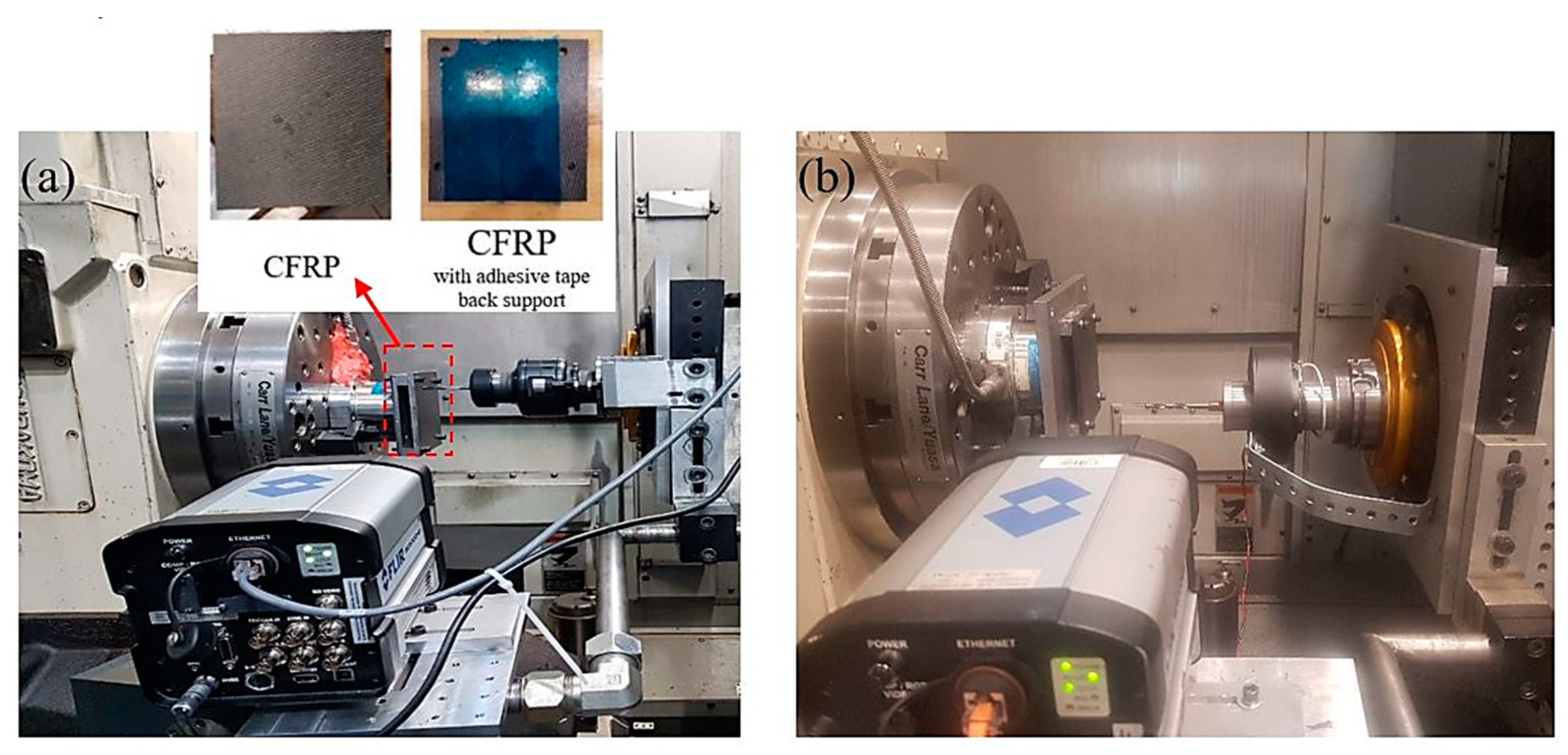
2. Experimental Setup

Figure 1 presents the experimental setup, which includes a five-axis Makino A88ɛ machining center. The axial tool oscillations for LF-VAD were generated using the MITIS tool holder PG8045B3_HSK-A100_ER40 [28], as shown in Figure 1a. The tool holder has a 2.5 cycle/rev fixed frequency ratio (F) with an adjustable amplitude (Am) range between 0.01 and 0.48 mm. Figure 1b shows the HF-VAD tool holder (designed by the National Research Center of Montreal) [29]. The experimental setup ensures continuous recording of the cutting forces and the cutting tool temperature at the exit surface. A U-shaped plate was used to create enough space behind the CFRP plate for direct thermal vision. A FLIR SC8000 infrared camera was used for the cutting tool tip thermal measurement. The thrust forces were monitored using a 9272 Kistler-type dynamometer and a Kistler multichannel charge amplifier (Type 5019B). Scanning electron microscopy type TESCAN VP.SEM was used for examining chip morphology, and for exit wall examination. The delamination analysis was performed with a Keyence optical microscope. Surface roughness values (Ra and Rz) were evaluated using a Surftest SJ-410 stylus profilometry, which has 0.0001 μm resolution.
Table 1 presents the experimental VAD machining parameters, cutting tool, and the CFRP material specification. Conventional cutting tests with identical machining conditions were performed for comparison purposes.

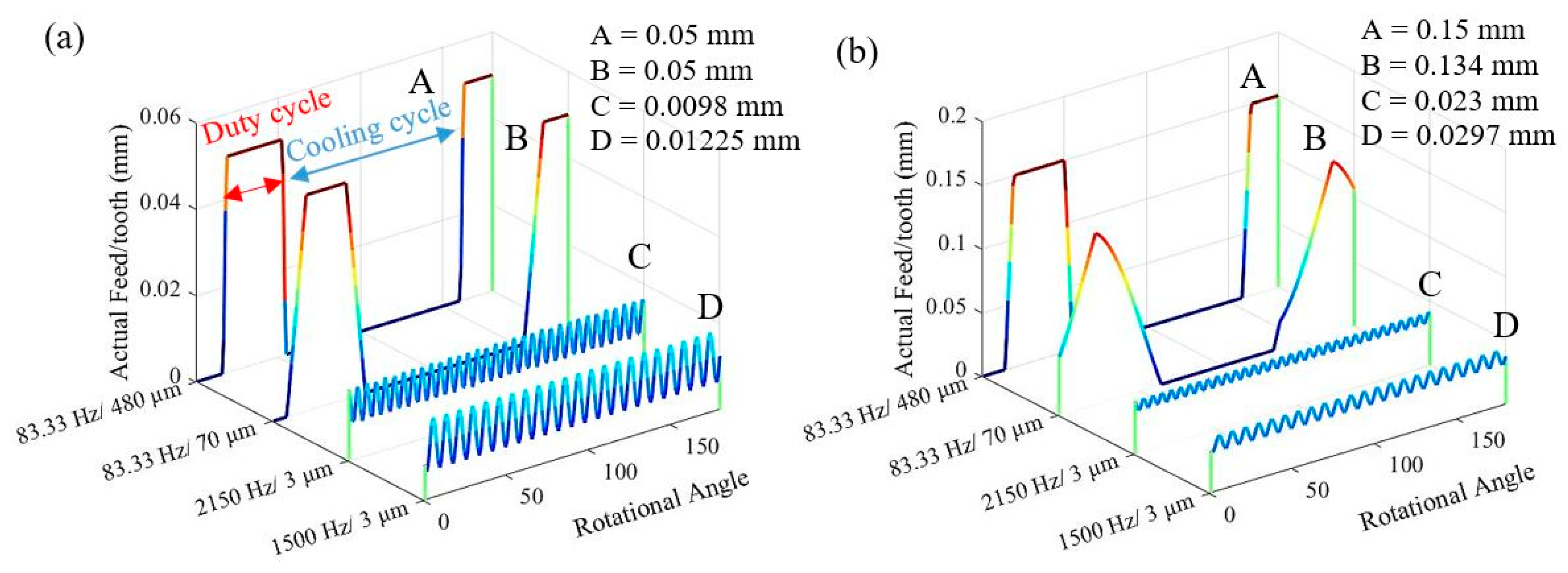
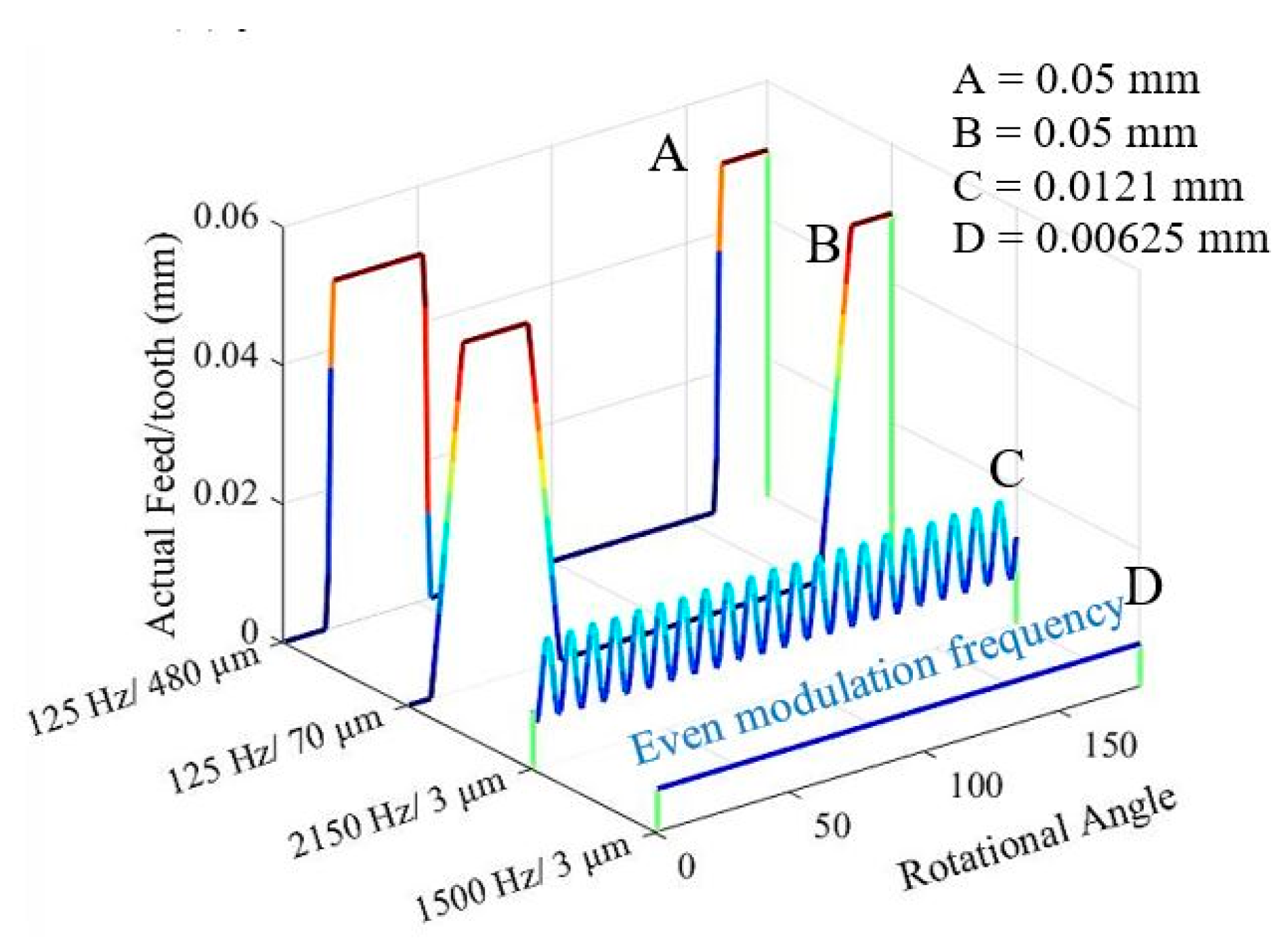
3. Kinematics of VAD

Figure 2 presents the effect of VAD on the actual uncut chip thickness at N = 2000 rpm for different machining conditions. Based on the instantaneous cutting edge position described in [31,32], the uncut chip thickness was calculated for VAD at the selected machining conditions. The Am range (0.07–0.48 mm) at LF-VAD (F = 83.33 Hz) resulted in chip segmentation as described in [3,33]. Consequently, periodic cooling cycles were generated, as shown in Figure 2a. In contrast, HF-VAD at Am = 3 µm did not display tool–workpiece separation. Consequently, a continuous cutting process is shown in Figure 2. HF-VAD showed a positive influence by reducing the uncut chip thickness up to 50% compared to CD. Moreover, increasing the cutting speed to N = 3000 rpm at HF-VAD with F = 1500 Hz, resulted in an even modulation frequency with a continuous cutting profile, as shown in Figure 3.
Based on the kinematics study of VAD at the selected machining conditions, the VAD influences are summarized as follows:
  • HF-VAD has the lowest mechanical load compared to LF-VAD and CD.
  • LF-VAD has a higher mechanical load compared to CD. Moreover, increasing the amplitude resulted in higher impact energy during the periodic tool engagement mechanism.
  • Based on the uncut chip thickness analysis, VAD has a lower thermal load compared to CD.
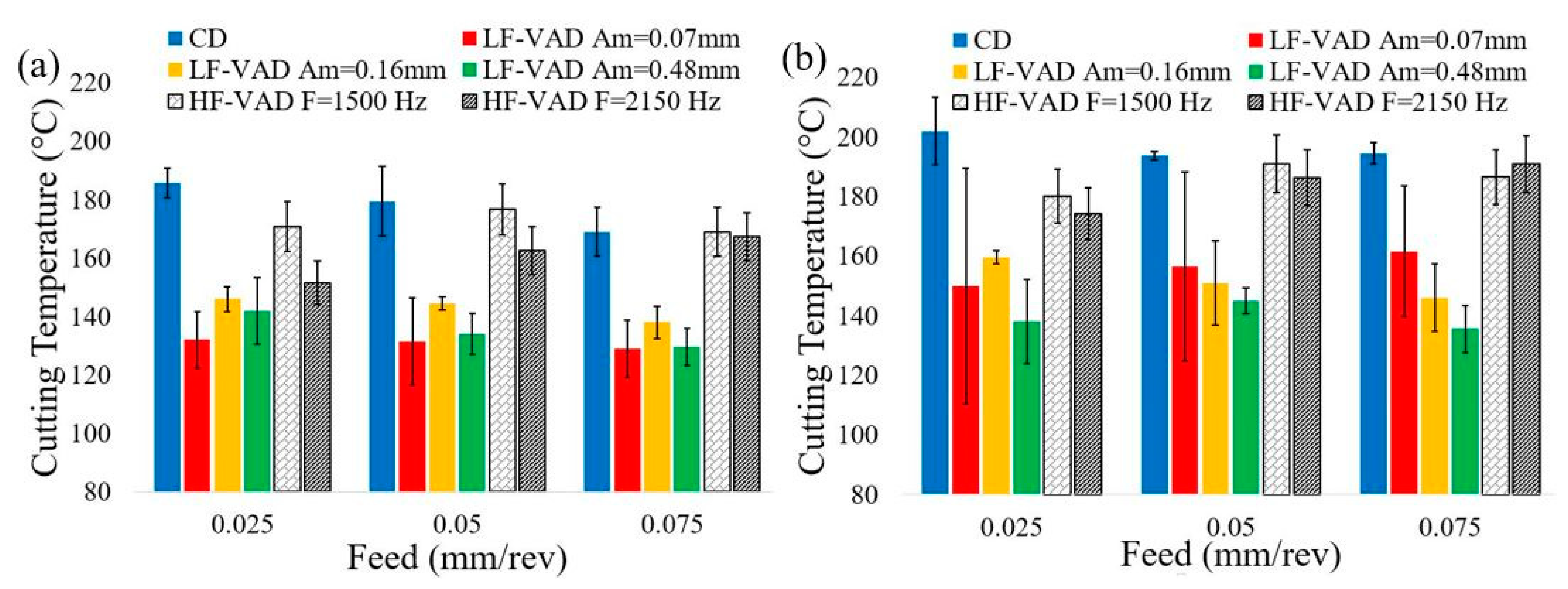
  • A reduction in the cutting temperature was achieved during LF-VAD cooling cycle.
  • Lower thrust force and thermal load are the main reasons to achieve a delamination-free process for utilization of VAD technology.

4. Results and Discussion

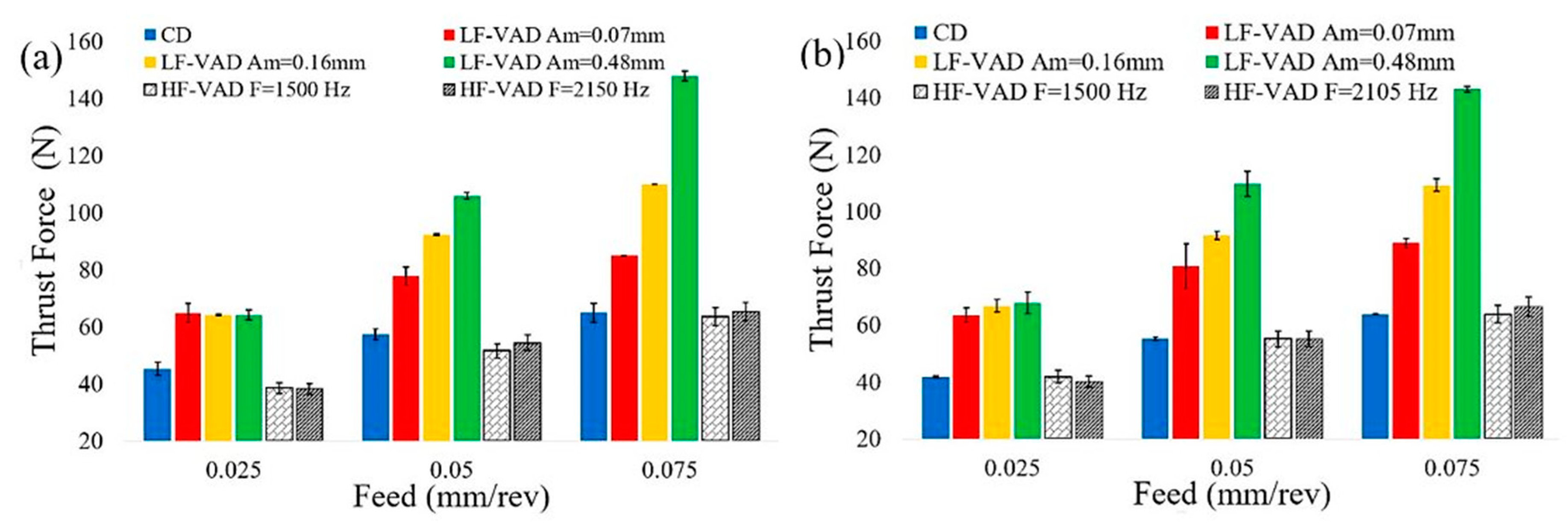
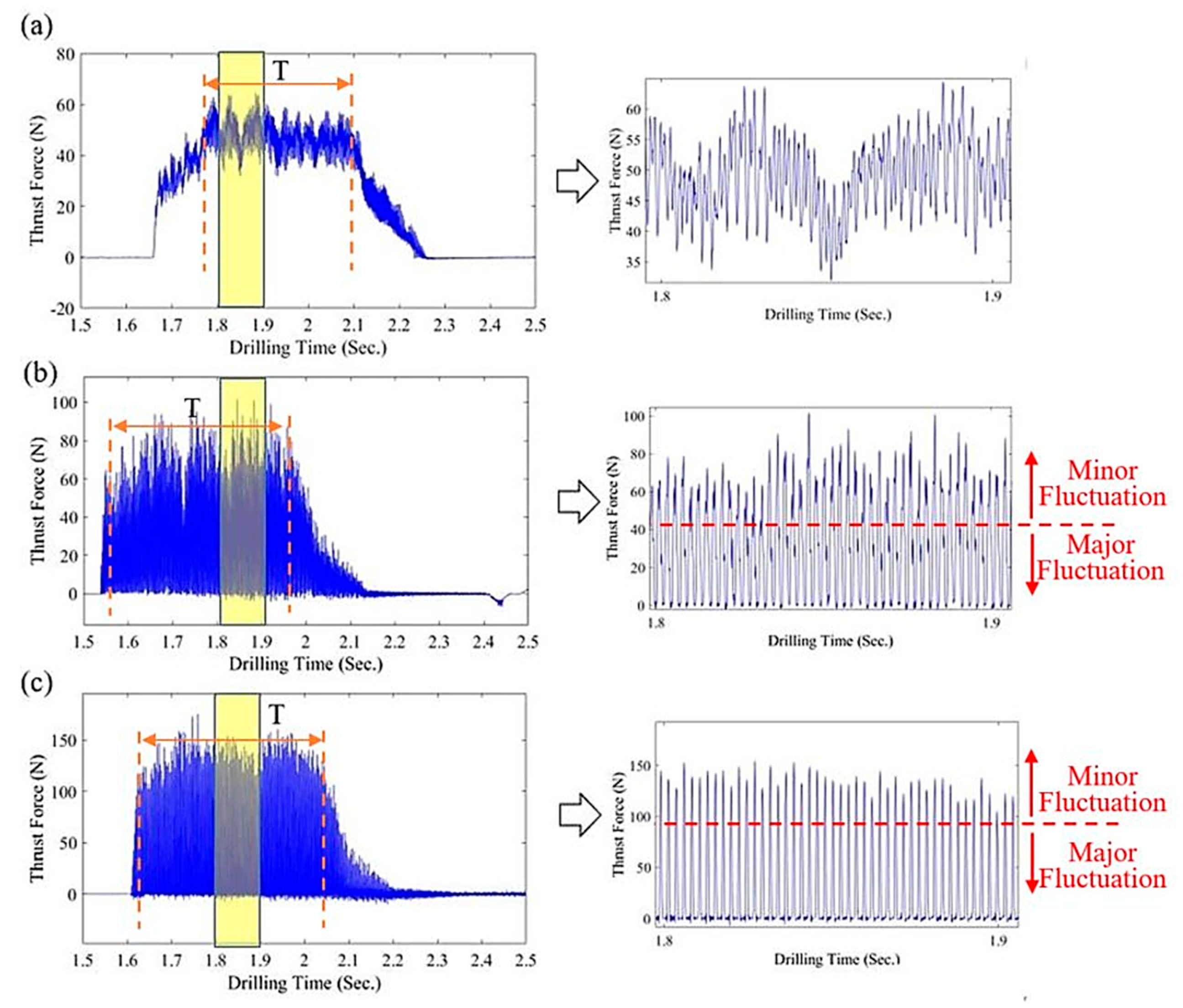
4.1. Effect of VAD on the Thrust Force

Figure 4 shows the effect of VAD on the thrust force measured at different machining conditions. For all machining conditions, the LF-VAD showed a higher thrust force compared to the CD. The measured thrust forces were 64 N to 143 N for LF-VAD and 41 N to 65 N for CD. These forces showed an increase of 30% to 120% compared to the CD. This increase could be attributed to the following:
  • High uncut chip thickness, as described in Section 3. This agrees with references [3,31,34].
  • Periodical tool impact caused a dynamic force component. This force adds to the total thrust force, as described in Section 3. These results agree with [3,4].
On the other hand, HF-VAD showed up to 16% reduction in the thrust force compared to the CD, at N = 2000 rpm. This reduction could be attributed to the following:
  • Lower uncut chip thickness compared to CD, as described in Section 3.
  • The ability of the axial tool oscillation to discard the non-cutting process under the chisel edge.
However, there is no apparent influence of HF-VAD at N = 3000 rpm on the thrust force. This could be attributed to the higher cutting temperature induced during the CD at N = 3000 rpm. Increasing the cutting temperature leads to material softening, and consequently the thrust force decreases. The HF-VAD at F = 2150 Hz resulted in a higher friction force that leads to an increase in the thrust force.
Figure 5 shows the effect of Am on the thrust force profile. For the CD, the steady cutting interval (T) showed low force fluctuation (35 N to 65 N) (see Figure 5a). This fluctuation could be attributed to the dynamic change of the rake face–fiber attack angle during tool rotation, as reported in [4]. In contrast, the LF-VAD thrust force profile showed major and minor fluctuation ranges. The minor fluctuation represents the dynamic change of the rake face–fiber attack angle, while the major fluctuation attributed to the tool duty and separation mechanism. The major fluctuation ranges were 0 N to 80 N for Am = 0.07 mm and 0 N to 148 N for Am = 0.48 mm (see Figure 5b,c).
The HF-VAD did not show significant variation in the thrust force profile compared to CD, which is attributed to the lower amplitude of vibration.

4.2. Effect of VAD on the Tool Temperature

Figure 6 shows the effect of the VAD on the cutting tool temperature at the exit surface. For all machining conditions, the VAD showed a lower cutting temperature compared to the CD. Tool temperatures measured during CD were 169 °C to 185 °C at N = 2000 rpm and 195 °C to 202 °C at N = 3000 rpm. The tool temperature showed a gradual reduction as cutting feed increased. This reduction is attributed to a lower duty time [20]. The exit tool temperatures for LF-VAD were 130 °C to 159 °C at N = 2000 rpm and 138 °C to 160 °C at N = 3000 rpm.
Increasing the LF-VAD amplitude from Am = 0.07 mm to Am = 0.48 led to a reduction in the cutting temperature, as seen in Figure 6b.
In contrast, at a lower thermal load (N = 2000 rpm), increasing the LF-VAD amplitude resulted in a higher impact velocity and larger uncut chip thickness (see Section 3).
Compared to the LF-VAD, the HF-VAD showed a limited reduction in the cutting temperature. The cutting temperature reduction was 13% for HF-VAD and 31% for LF-VAD. The higher reduction of LF-VAD could be attributed to the interrupted cutting process. This process reduces the cyclic tool duty time, as described in Section 3.
For all machining conditions, the HF-VAD at F = 2150 Hz showed a lower cutting temperature compared to HF-VAD at F = 1500 Hz and CD. This reduction is attributed to the lower uncut chip thickness at N = 2000 rpm, as described in Figure 2. For higher cutting speed N = 3000 rpm, an even Wf leads to a constant tool–workpiece contact area, and accordingly higher heat concentration. The HF-VAD at F = 1500 Hz showed lower uncut chip thickness, however the negative influence of constant tool–workpiece contact area is more dominant.

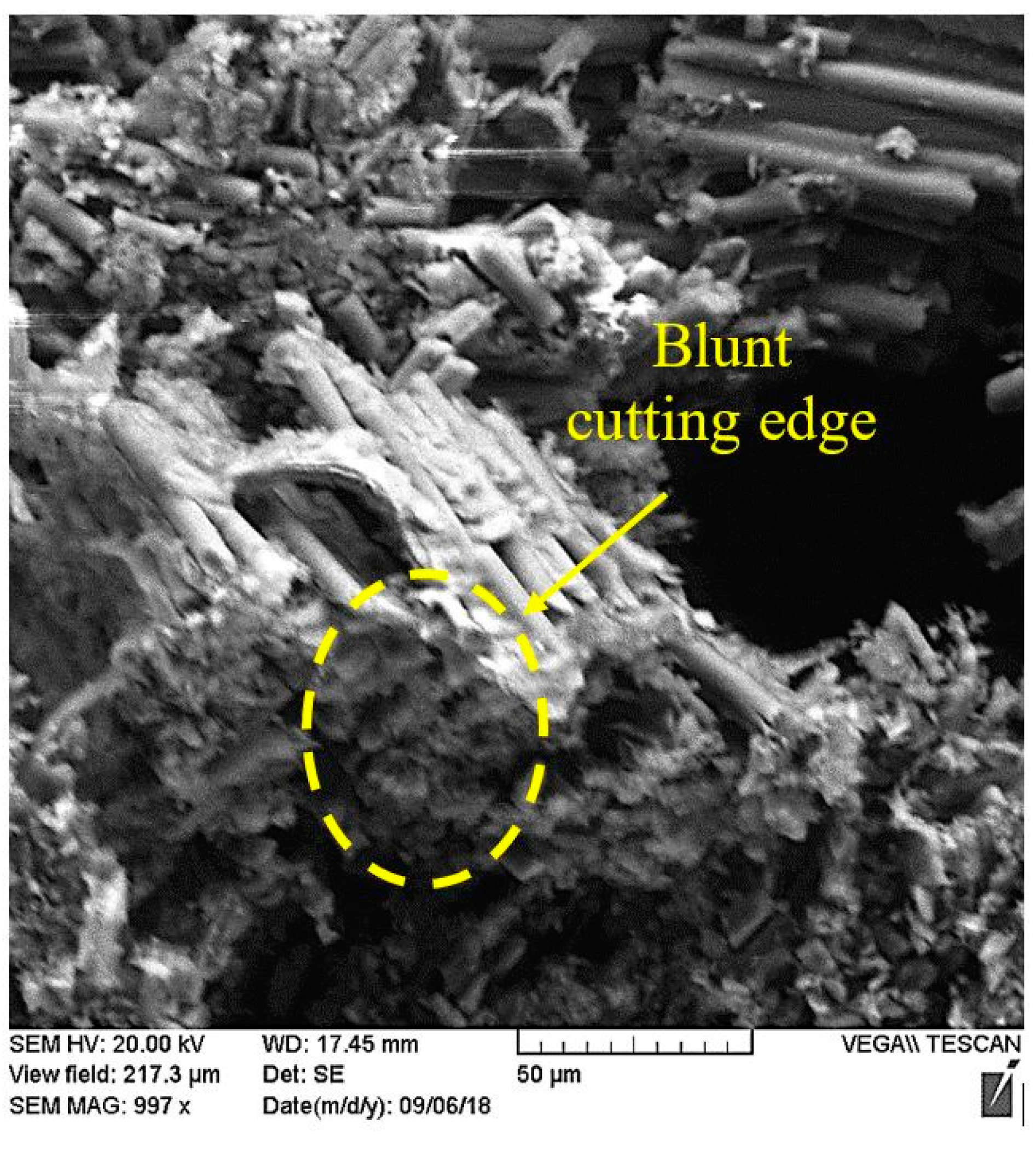
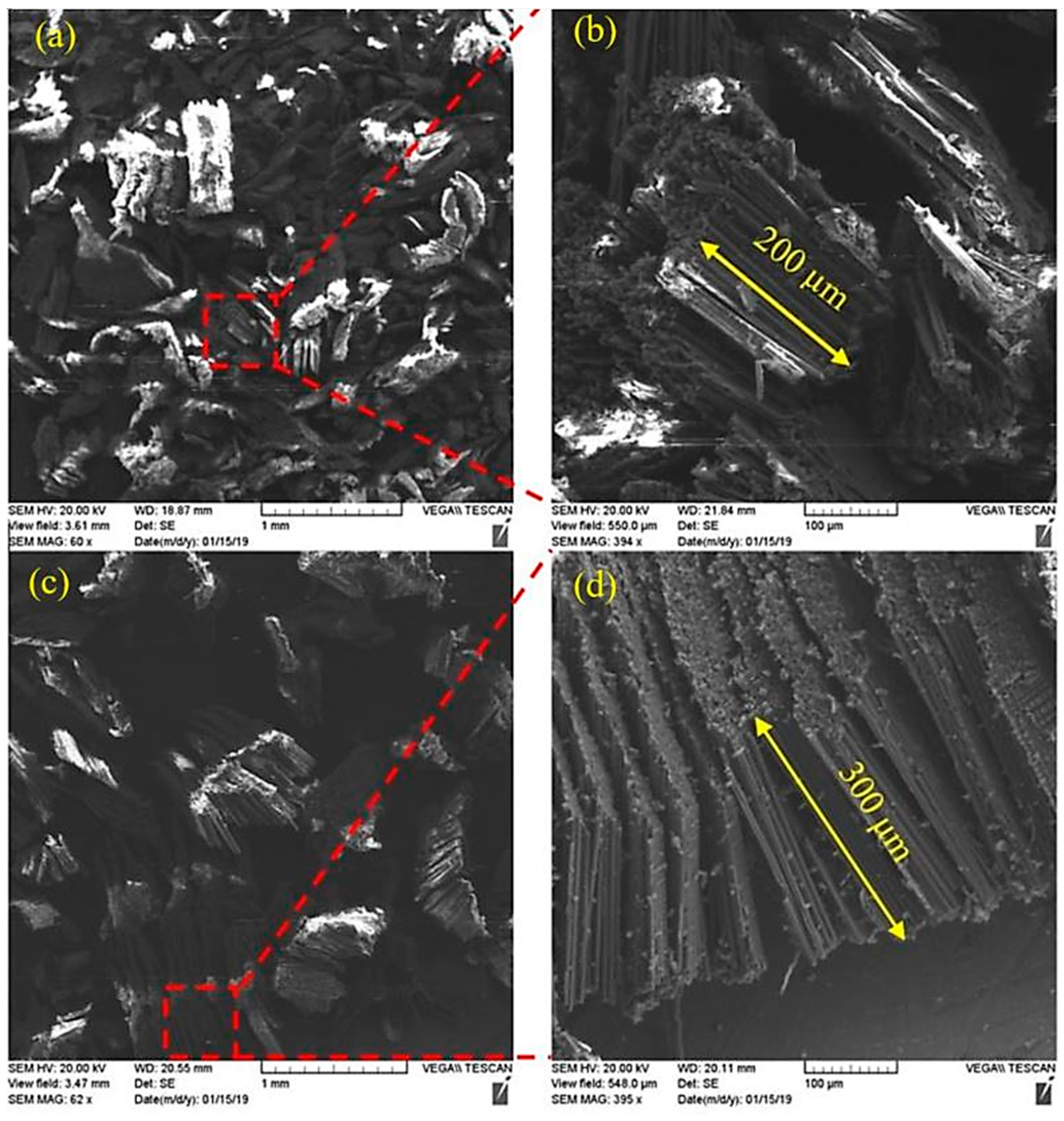
4.3. Chip Morphology

The non-cutting process under the chisel edge is a major factor resulting in fiber extrusion and delamination damage. Superimposing a harmonic motion over the conventional axial feed results in a periodic chisel edge movement. This impact loading reduces the energy absorbed by the material for the following reasons [35,36]:
  • There is a localized material response over a small region [36,37].
  • The non-cutting process under the chisel edge is discarded through the axial oscillation mechanism.
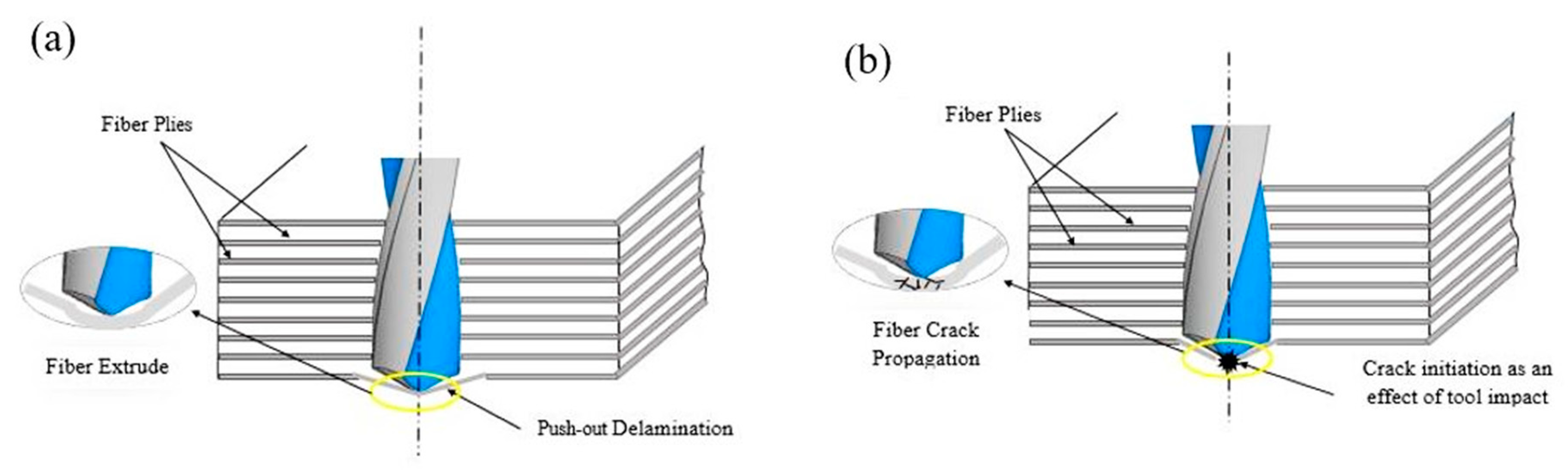
  • A conically-shaped shear zone is created at the impact point (the chisel edge) [36].
Figure 7 presents a schematic diagram to describe the fiber behavior at steady-state tool movement (CD) and the periodical chisel edge impact mechanism. Further analysis was performed on the chips collected using scanning electron microscopic (SEM) examination, to investigate the VAD influence on the fiber-cutting process. The chips collected during LF-VAD appear sharper and more organized (see Figure 8). On the other hand, Figure 9 shows a blunt fiber during CD. This observation could be attributed to the following:
  • Changing the cutting mechanism under the chisel edge to periodic impact.
  • Lower cutting temperature at LF-VAD resulting in maintaining the material stiffness, and consequently resisting the fiber matrix debonding mechanism.
Figure 10 shows the effect of LF-VAD amplitude on the machined fiber length at f = 0.075 mm/rev and N = 3000 rpm. Increasing the LF-VAD amplitude led to increased machined fiber length by 50%. The machined fiber length was 200 µm at Am = 0.07 mm and 300 µm at Am = 0.48 mm. On the other hand, the maximum fiber length during CD was 80 µm. This increase is attributed to the influence of cyclic cooling, as presented in Section 3. Such trends are comparable to the UAD investigation presented in [24].

4.4. Geometric and Surface Integrity
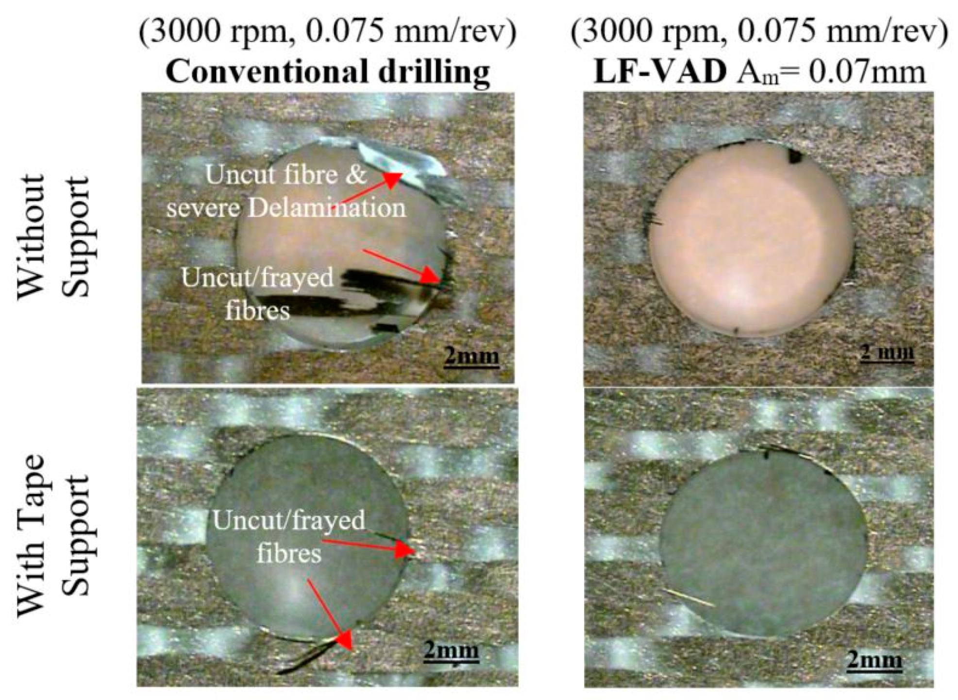
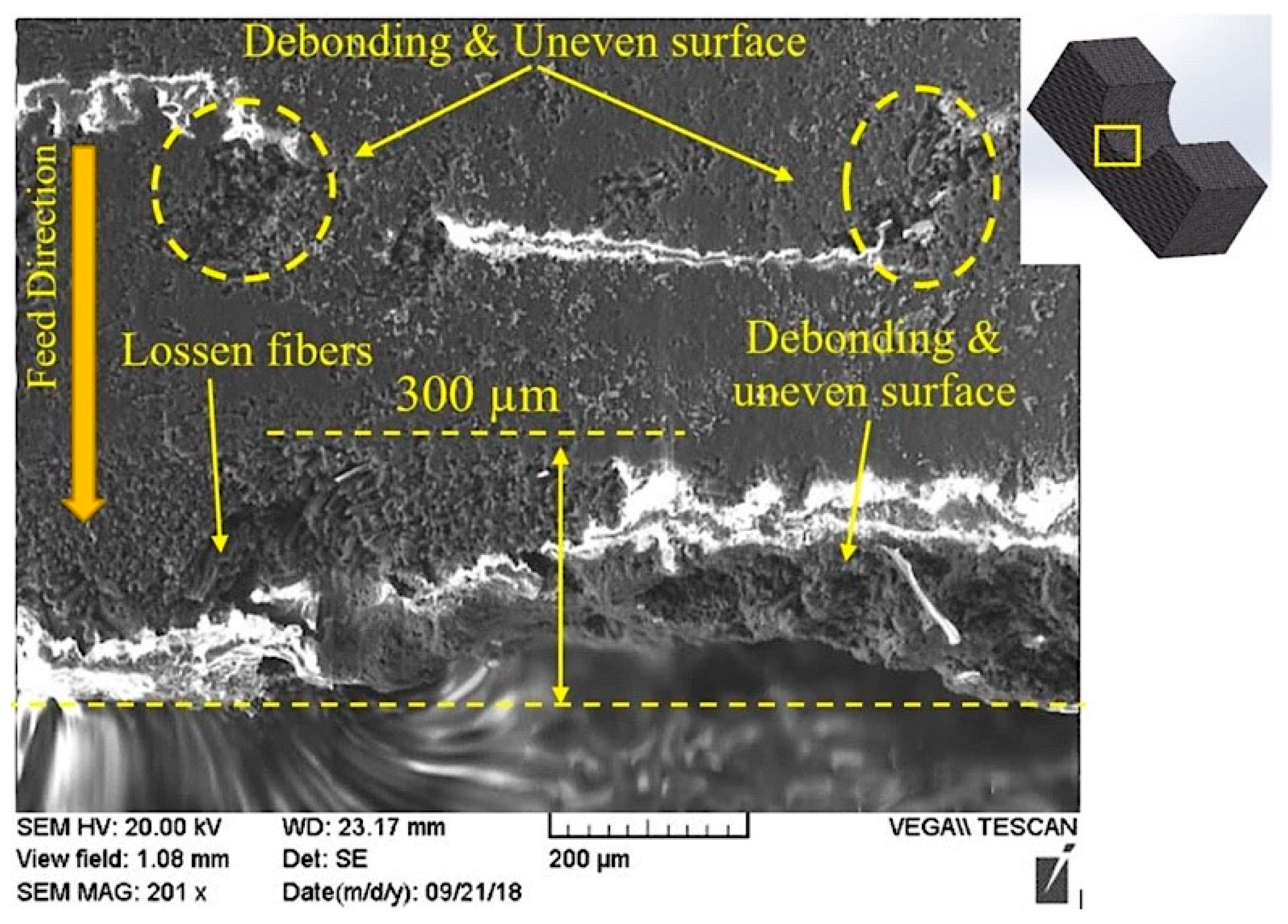
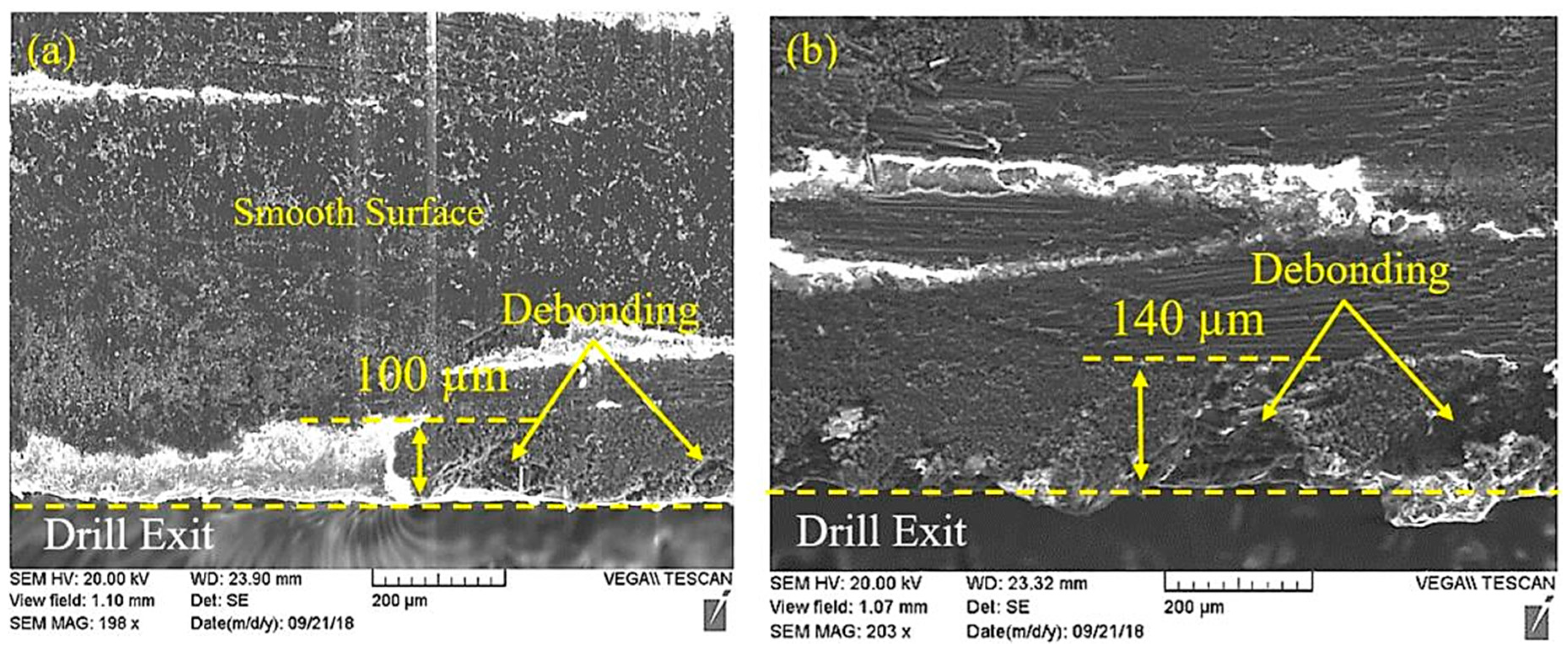
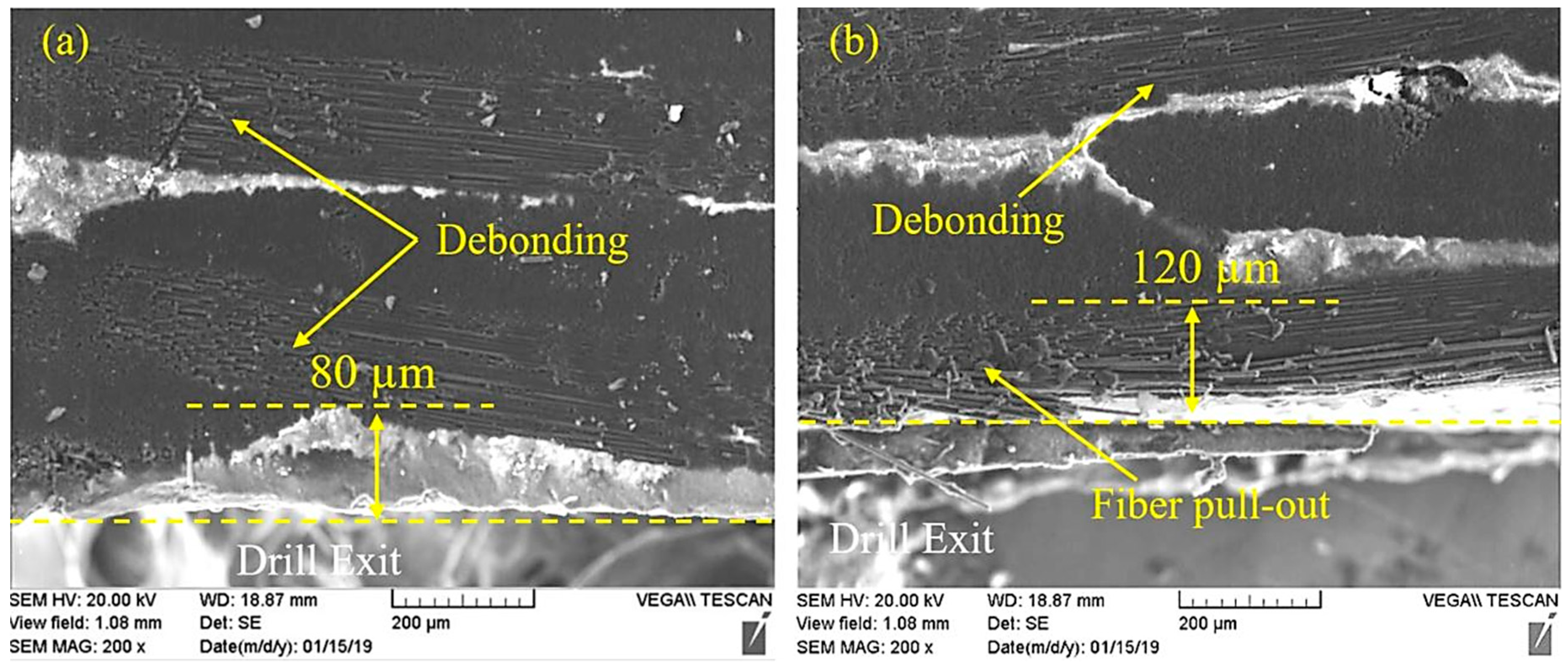
4.4.1. Delamination

Figure 11 compares the effect of LF-VAD and CD on the exit delamination in the case of free and adhesive tap back support. For all machining parameters, LF-VAD showed a significant enhancement at exit delamination (including the free support case). The delamination factor ‘φd’ was evaluated using Equation (1), as described in [3].
φ d = D a c t u a l D n o m i n a l D n o m i n a l ,
where Dactual is the diameter of a circle including the circumscribing delamination, while Dnominal represents the nominal hole diameter.
The delamination factor for CD was ≤0.5 at N = 2000 rpm and ≥0.5 at N = 3000 rpm, at free support. On the other hand, the φd for LF-VAD was ≤0.2 for all machining conditions. This enhancement is attributed to lower cutting temperature and the proper fiber-cutting process under the chisel edge.
For adhesive back support, the delamination factor was ≤0.5 for CD and ≤0.2 for LF-VAD, at all machining conditions. The adhesive tape increased the matrix stiffness and reduces the thrust force negative effect, and consequently the fiber-cutting process is enhanced.
The delamination factor achieved was lower than the one reported in [20] for LF-VAD, due to the higher frequency range which reduces the cyclic tool duty interval. Moreover, using a higher modulation amplitude showed a smaller delamination factor reduction compared to the LF-VAD study reported in [4], for the same reason.
The HF-VAD showed a lower delamination factor compared to the CD, for all machining conditions. The maximum delamination factor measured during HF-VAD was 0.2. The free delamination process was achieved at the maximum machining load f = 0.075 mm/rev and N = 3000 rpm, as shown in Figure 12. This enhancement is attributed to lower uncut chip thickness, cutting temperature, and thrust force (see Section 3, Section 4.1, and Section 4.2).

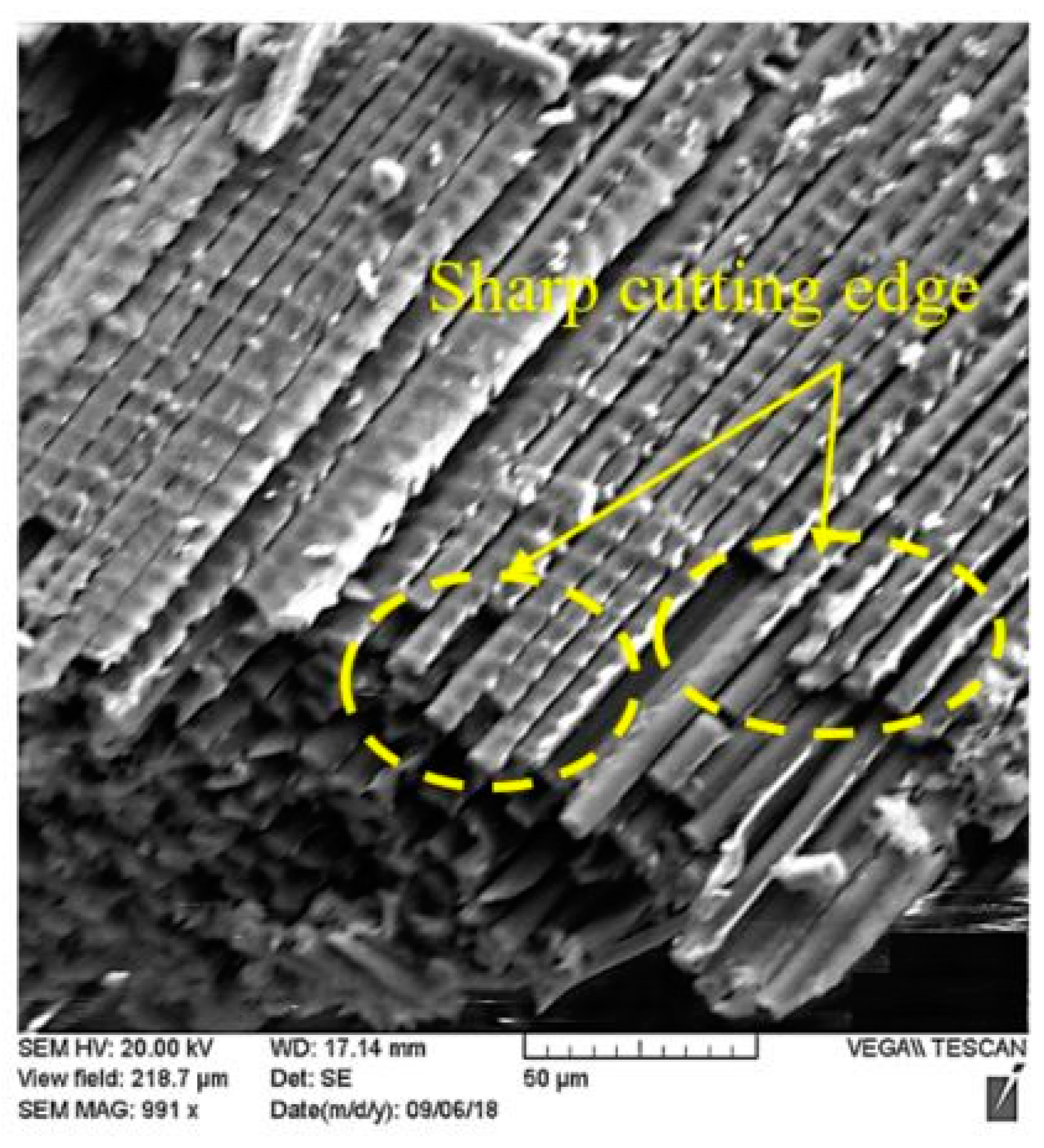
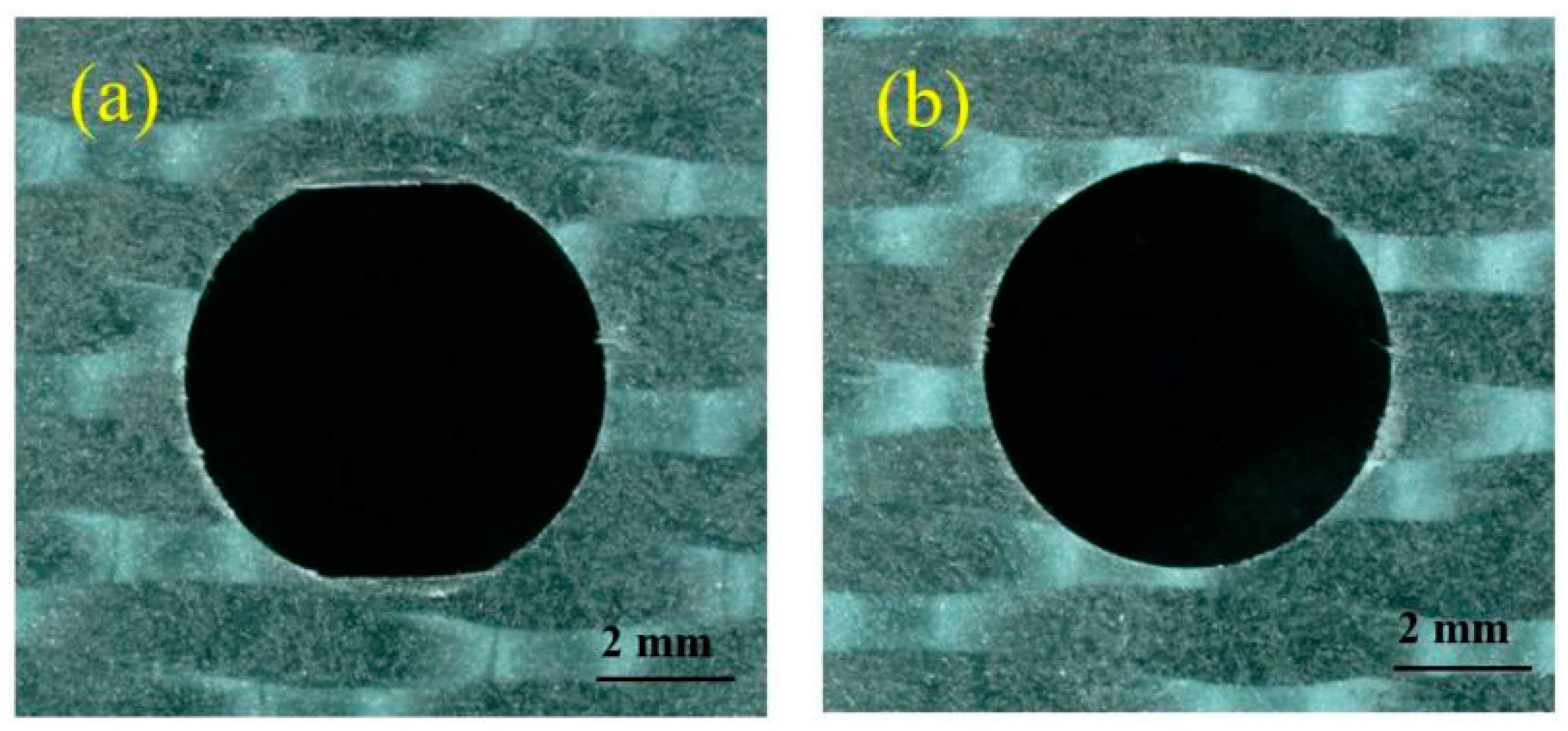
4.4.2. Exit Hole Wall Quality

Matrix debonding, fiber pull-out, and uneven surface are typical defects during CD [7]. Figure 13 presents the effect of CD on the exit hole wall. The high cutting temperature leads to matrix melting and, consequently, severe debonding damage is initiated. This observation agrees with the temperature analysis in Section 4.2. Debonding damage reduces the matrix resistance, and consequently the fiber pull-out damage. The damaged area observed extended to 300 µm from the exit surface. LF-VAD showed a significant enhancement to the machining surface. The damaged area was reduced by more than 50% with a smooth machined surface, as shown in Figure 14. This enhancement is attributed to the following:
Figure 15 presents the effect of HF-VAD on the exit wall quality. Lower uncut chip thickness led to cutting energy reduction. As a consequence, the total damage reduced to 80 µm at F = 1500 Hz and to 120 µm at F = 2150 Hz. The higher damaged area at F = 2150 Hz could be attributed to the higher tool–wall friction forces.

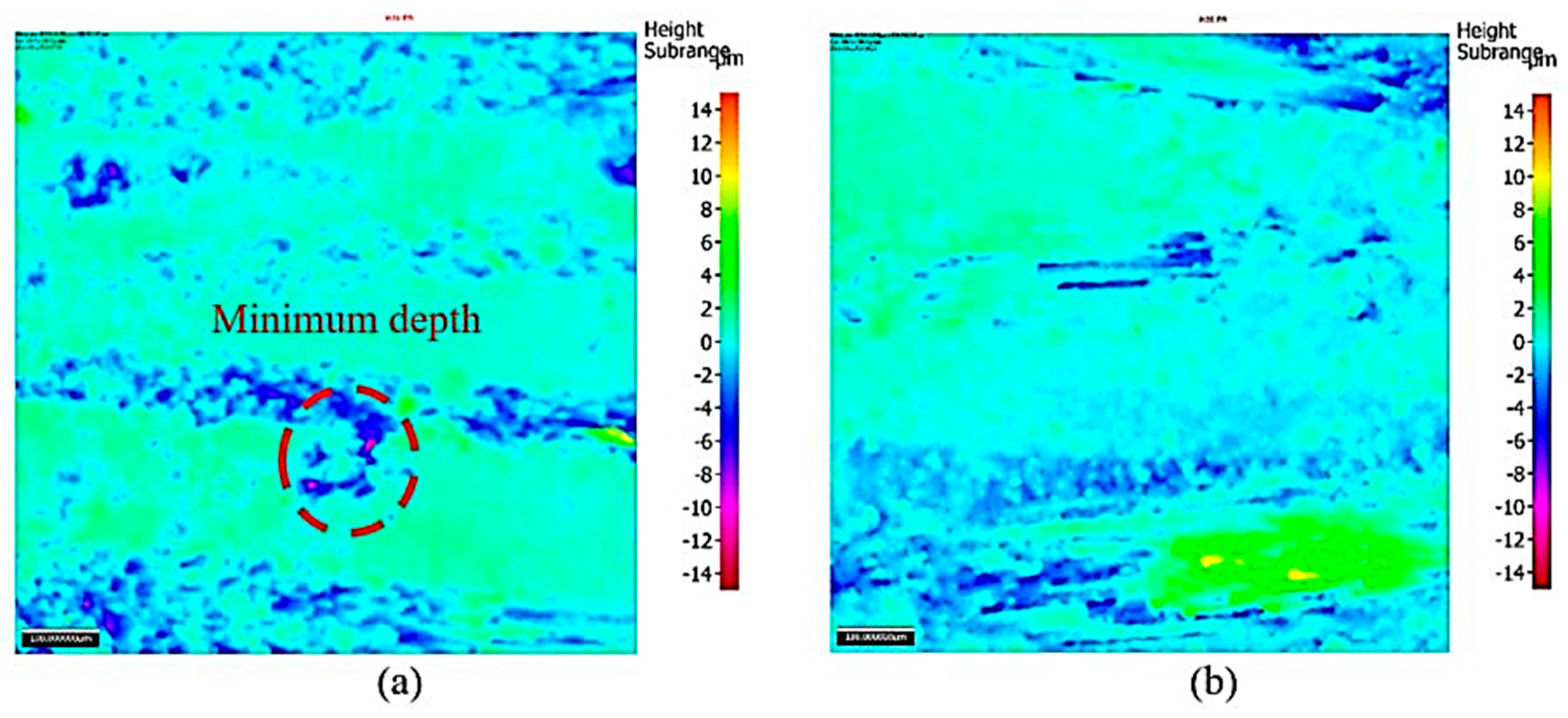
4.4.3. Surface Roughness

Analysis of the surface roughness (Ra, Rz) at N = 2000 rpm indicated no significant difference between VAD and CD. For all machining conditions, the maximum Ra and Rz were 1.5 µm and 10 µm, respectively, for both machining techniques. However, increasing the cutting speed to N = 3000 rpm resulted in a higher Ra and Rz for CD (3 µm and 17 µm), while the maximum Ra and Rz for VAD were 1.5 µm and 10 µm, respectively. This reduction is attributed to the lower cutting temperature which enhances the matrix stiffness.
Figure 16 shows the surface texture analysis for VAD and CD machined surfaces. The minimum depth was 6 µm for VAD and 14.5 µm for CD. This observation confirms the benefits of VAD regarding cutting temperature, as described in Section 4.2.

5. Conclusions

This experimental study evaluated the machining response during vibration-assisted drilling (VAD) of CFRP material. The LF-VAD study results are obtained at Wf = 2.5 cycles/rev (F = 83.3 Hz and 125 Hz) for different cutting speeds, feeds, and amplitudes. On the other hand, the HF-VAD study results are obtained at F = 1500 Hz and 2150 Hz and Am = 3 µm for different machining conditions. The kinematics of the instantaneous cutting tool position were used to study the effect of VAD machining parameters on the mechanical and thermal load compared to conventional drilling. Furthermore, the study compared the effect of LF-VAD on exit delamination, to the CD with and without flash breaker back support. The following are of the main experimental observations:
  • For all machined parameters, LF-VAD showed higher thrust forces compared to the CD. This increase is due to higher uncut chip thickness and tool impact.
  • HF-VAD showed up to 16% reduction in the thrust force compared to CD.
  • VAD showed a significant reduction in cutting temperature compared to CD. The cutting temperature reduction was 31% for LF-VAD and 13% for HF-VAD.
  • Free delamination drilling was successfully achieved by using VAD due to lower thermal load. The delamination factor for CD was ≤0.5 at N = 2000 rpm and ≥0.5 at N = 3000 rpm respectively. On the other hand, the VAD resulted in delamination factor ≤0.2 for all machining conditions.
  • The adhesive tape back support reduced the delamination factor for CD to ≤0.5 for all machining conditions.
  • LF-VAD resulted in a longer machined fiber compared to CD. The fiber length increased from 80 µm at CD to 300 µm at LF-VAD with Am = 0.48 mm.
  • Based on the SEM examination of the machined wall surface, VAD resulted in a significant enhancement to the machined surface quality compared to the CD.

Author Contributions

R.H.: performed experiments, analysis, and data interpretation; wrote the first draft of the manuscript; helped with submitting the final manuscript to the journal (corresponding author). A.S.: helped with the experiments and analysis; revised the manuscript. M.A.E.: revised and edited the manuscript and gave the final approval to be submitted. M.H.A.: revised the manuscript.

Funding

This research received no external funding.

Acknowledgments

The experimental work in this study was performed using the laboratories of the Canadian National Research Council (CNRC), Aerospace and Manufacturing Group, Montreal, Canada. The technical support is greatly appreciated.

Conflicts of Interest

The authors declare no conflict of interest.

References

  1. Soo, S.L.; Abdelhafeez, A.M.; Li, M.; Hood, R.; Lim, C.M. The drilling of carbon fibre composite–aluminium stacks and its effect on hole quality and integrity. Proc. Inst. Mech. Eng. Part B J. Eng. Manuf. 2017, 233, 1323–1331. [Google Scholar] [CrossRef]
  2. Brinksmeier, E.; Janssen, R. Drilling of multi-layer composite materials consisting of carbon fiber reinforced plastics (CFRP), titanium and aluminum alloys. CIRP Ann. Manuf. Technol. 2002, 51, 87–90. [Google Scholar] [CrossRef]
  3. Hussein, R.; Sadek, A.; Elbestawi, M.A.; Attia, M. Low-frequency vibration-assisted drilling of hybrid CFRP/Ti6Al4V stacked material. Int. J. Adv. Manuf. Technol. 2018, 98, 2801–2817. [Google Scholar] [CrossRef]
  4. Debnath, K.; Singh, I. Low-frequency modulation-assisted drilling of carbon-epoxy composite laminates. J. Manuf. Process. 2017, 25, 262–273. [Google Scholar] [CrossRef]
  5. Che, D.; Saxena, I.; Han, P.; Guo, P.; Ehmann, K.F. Machining of carbon fiber reinforced plastics/polymers: A literature review. J. Manuf. Sci. Eng. 2014, 136, 034001. [Google Scholar] [CrossRef]
  6. Liu, D.; Tang, Y.; Cong, W. A review of mechanical drilling for composite laminates. Compos. Struct. 2012, 94, 1265–1279. [Google Scholar] [CrossRef]
  7. Fu, R.; Jia, Z.; Wang, F.; Jin, Y.; Sun, D.; Yang, L.; Cheng, D. Drill-exit temperature characteristics in drilling of UD and MD CFRP composites based on infrared thermography. Int. J. Mach. Tools Manuf. 2018, 135, 24–37. [Google Scholar] [CrossRef]
  8. Persson, E.; Eriksson, I.; Zackrisson, L. Effects of hole machining defects on strength and fatigue life of composite laminates. Compos. Part A Appl. Sci. Manuf. 1997, 28, 141–151. [Google Scholar] [CrossRef]
  9. Chen, W.-C. Some experimental investigations in the drilling of carbon fiber-reinforced plastic (CFRP) composite laminates. Int. J. Mach. Tools Manuf. 1997, 37, 1097–1108. [Google Scholar] [CrossRef]
  10. Gaitonde, V.; Karnik, S.; Rubio, J.C.; Correia, A.E.; Abrao, A.; Davim, J.P. Analysis of parametric influence on delamination in high-speed drilling of carbon fiber reinforced plastic composites. J. Mater. Process. Technol. 2008, 203, 431–438. [Google Scholar] [CrossRef]
  11. Romoli, L.; Dini, G. Experimental study on the influence of drill wear in CFRP drilling processes. In Proceedings of the ICME 08, Naples, Italy, 23–25 July 2008. [Google Scholar]
  12. Linbo, Z.; Lijiang, W.; Xin, W. Study on vibration drilling of fiber reinforced plastics with hybrid variation parameters method. Compos. Part A Appl. Sci. Manuf. 2003, 34, 237–244. [Google Scholar] [CrossRef]
  13. Tagliaferri, V.; Caprino, G.; Diterlizzi, A. Effect of drilling parameters on the finish and mechanical properties of GFRP composites. Int. J. Mach. Tools Manuf. 1990, 30, 77–84. [Google Scholar] [CrossRef]
  14. Ho-Cheng, H.; Dharan, C. Delamination during drilling in composite laminates. J. Eng. Ind. 1990, 112, 236–239. [Google Scholar] [CrossRef]
  15. Xu, J.; Li, C.; Mi, S.; An, Q.; Chen, M. Study of drilling-induced defects for CFRP composites using new criteria. Compos. Struct. 2018, 201, 1076–1087. [Google Scholar] [CrossRef]
  16. Durante, M.; Boccarusso, L.; De Fazio, D.; Langella, A. Circular cutting strategy for drilling of carbon fiber-reinforced plastics (CFRPs). Mater. Manuf. Process. 2019, 34, 1–13. [Google Scholar] [CrossRef]
  17. Shyha, I.S.; Soo, S.L.; Aspinwall, D.; Bradley, S.; Perry, R.; Harden, P.; Dawson, S. Hole quality assessment following drilling of metallic-composite stacks. Int. J. Mach. Tools Manuf. 2011, 51, 569–578. [Google Scholar] [CrossRef]
  18. Shyha, I.S.; Aspinwall, D.K.; Soo, S.L.; Bradley, S. Drill geometry and operating effects when cutting small diameter holes in CFRP. Int. J. Mach. Tools Manuf. 2009, 49, 1008–1014. [Google Scholar] [CrossRef]
  19. Zhang, C.; Lu, M. A novel variable-dimensional vibration-assisted actuator for drilling CFRP. Int. J. Adv. Manuf. Technol. 2018, 99, 3049–3063. [Google Scholar] [CrossRef]
  20. Sadek, A.; Attia, M.; Meshreki, M.; Shi, B. Characterization and optimization of vibration-assisted drilling of fibre reinforced epoxy laminates. CIRP Ann. Manuf. Technol. 2013, 62, 91–94. [Google Scholar] [CrossRef]
  21. Wang, X.; Wang, L.; Tao, J. Investigation on thrust in vibration drilling of fiber-reinforced plastics. J. Mater. Process. Technol. 2004, 148, 239–244. [Google Scholar] [CrossRef]
  22. Makhdum, F.; Norddin, D.N.P.; Roy, A.; Silberschmidt, V.V. Ultrasonically Assisted Drilling of Carbon Fibre Reinforced Plastics; Solid State Phenomena; Trans Tech Publications: Leicestershire, UK, 2012; pp. 170–175. [Google Scholar]
  23. Makhdum, F.; Phadnis, V.A.; Roy, A.; Silberschmidt, V.V. Effect of ultrasonically-assisted drilling on carbon-fibre-reinforced plastics. J. Sound Vib. 2014, 333, 5939–5952. [Google Scholar] [CrossRef] [Green Version]
  24. Gupta, A.; Barnes, S.; McEwen, I.; Kourra, N.; Williams, M.A. Study of cutting speed variation in the ultrasonic assisted drilling of carbon fibre composites. In Proceedings of the ASME 2014 International Mechanical Engineering Congress and Exposition, Montreal, QC, Canada, 14–20 November 2014; p. V02BT02A038. [Google Scholar]
  25. Makhdum, F.; Jennings, L.T.; Roy, A.; Silberschmidt, V.V. Cutting forces in ultrasonically assisted drilling of carbon fibre-reinforced plastics. J. Phys. Conf. Ser. 2012, 382, 012019. [Google Scholar] [CrossRef] [Green Version]
  26. Phadnis, V.A.; Makhdum, F.; Roy, A.; Silberschmidt, V.V. Experimental and numerical investigations in conventional and ultrasonically assisted drilling of CFRP laminate. Procedia CIRP 2012, 1, 455–459. [Google Scholar] [CrossRef]
  27. Sanda, A.; Arriola, I.; Navas, V.G.; Bengoetxea, I.; Gonzalo, O. Ultrasonically assisted drilling of carbon fibre reinforced plastics and Ti6Al4V. J. Manuf. Process. 2016, 22, 169–176. [Google Scholar] [CrossRef]
  28. MITIS Engineer MITIS Tool Holder. Available online: https://www.mitis.fr/ (accessed on 20 October 2017).
  29. Panju, J.; Meshreki, M.; Attia, M. Design of a Retrofittable Spindle Attachment for High Frequency Vibration-Assisted Drilling. In Proceedings of the ASME 2014 International Mechanical Engineering Congress and Exposition, Montreal, QC, Canada, 14–20 November 2014; p. V02AT02A034. [Google Scholar]
  30. Airtech Advanced Materials Group. Flash Breaker Data Sheet. Available online: https://www.freemansupply.com/datasheets/Airtech/flashbreaker125.pdf (accessed on 16 July 2018).
  31. Pecat, O.; Meyer, I. Low Frequency Vibration Assisted Drilling of Aluminium Alloys; Advanced Materials Research; Trans Tech Publications: Zurich, Switzerland, 2013; pp. 131–138. [Google Scholar]
  32. Sadek, A.; Meshreki, M.; Attia, M. Effect of Tool Kinematics on the Drilling Forces and Temperature in Low Frequency High Amplitude Vibration Assisted Drilling. In Proceedings of the ASME 2014 International Mechanical Engineering Congress and Exposition, Montreal, QC, Canada, 14–20 November 2014; p. V02AT02A035. [Google Scholar]
  33. Zhang, D.; Wang, L. Investigation of chip in vibration drilling. Int. J. Mach. Tools Manuf. 1998, 38, 165–176. [Google Scholar] [CrossRef]
  34. Sadek, A. Vibration Assisted Drilling of Multidirectional Fiber Reinforced Polymer Laminates. Ph.D. Thesis, McGill University Libraries, Montreal, QC, Canada, 2014. [Google Scholar]
  35. Chen, Q.; Guan, Z.; Li, Z.; Ji, Z.; Zhuo, Y. Experimental investigation on impact performances of GLARE laminates. Chin. J. Aeronaut. 2015, 28, 1784–1792. [Google Scholar] [CrossRef] [Green Version]
  36. Cantwell, W.; Morton, J. Comparison of the low and high velocity impact response of CFRP. Composites 1989, 20, 545–551. [Google Scholar] [CrossRef]
  37. Cantwell, W. The influence of target geometry on the high velocity impact response of CFRP. Compos. Struct. 1988, 10, 247–265. [Google Scholar] [CrossRef]
Figure 1. The developed experimental setup for (a) low-frequency vibration-assisted drilling (LF-VAD) and (b) high-frequency vibration-assisted drilling (HF-VAD).
Jmmp 03 00023 g001
Figure 2. Effect of vibration-assisted drilling (VAD) frequency and amplitude on the uncut chip thickness at (a) feed (f) = 0.025 mm/rev and (b) f = 0.075 mm/rev.
Jmmp 03 00023 g002
Figure 3. Effect of vibration-assisted drilling frequency and amplitude on the uncut chip thickness at f = 0.025 mm/rev and N = 3000 rpm.
Jmmp 03 00023 g003
Figure 4. Effect of VAD on the thrust force at (a) N = 2000 rpm (b) N = 3000 rpm.
Jmmp 03 00023 g004
Figure 5. Effect of the LF-VAD on the thrust force profile at f = 0.075 mm/rev and N = 3000 rpm for (a) CD (b) Am = 0.07 mm (c) Am = 0.48 mm.
Jmmp 03 00023 g005
Figure 6. Effect of VAD on the cutting temperature at (a) N = 2000 rpm (b) N = 3000 rpm.
Jmmp 03 00023 g006
Figure 7. Effect of drilling technique on the carbon fiber-reinforced polymers (CFRP) fibers (a) CD (b) VAD.
Jmmp 03 00023 g007
Figure 8. Effect of LF-VAD on the CFRP chips at f = 0.075 mm/rev, N = 3000 rpm, and Am = 0.48 mm.
Jmmp 03 00023 g008
Figure 9. Effect of CD on the CFRP chips at f = 0.075 mm/rev and N = 3000 rpm.
Jmmp 03 00023 g009
Figure 10. Effect of LF-VAD amplitude on the fiber length: (a,b) Am = 0.07 mm; (c,d) Am = 0.48 mm.
Jmmp 03 00023 g010
Figure 11. Effect of cutting technique, adhesive back support, and machining parameters on the exit delamination.
Jmmp 03 00023 g011
Figure 12. Effect of HF-VAD on the exit delamination at f = 0.075 mm/rev and N = 3000 rpm for (a) F = 1500 Hz and (b) F = 2150 Hz.
Jmmp 03 00023 g012
Figure 13. The SEM examination of CD machined hole at f = 0.075 mm /rev and N = 3000 rpm.
Jmmp 03 00023 g013
Figure 14. The scanning electron microscopic (SEM) examination of LF-VAD machined hole at f = 0.075 mm/rev and N = 3000 rpm on the exit surface for (a) Am = 0.07 mm and (b) Am = 0.48 mm.
Jmmp 03 00023 g014
Figure 15. The SEM examination of HF-VAD machined hole at f = 0.075 mm/rev and N = 3000 rpm on the exit surface for (a) F = 1500 Hz and (b) F = 2150 Hz.
Jmmp 03 00023 g015
Figure 16. Effect of machining technique on the CFRP surface texture measurement: (a) CD; (b) LF-VAD at Am = 0.48 mm.
Jmmp 03 00023 g016
Table 1. Applied cutting conditions, cutting tool, and workpiece material.
Machining Parameters
Cutting speeds N (rpm)2000 and 3000
Feed f (mm/rev)0.025, 0.05, and 0.075
Cooling mediumDry
LF-VADHF-VAD
Amplitude Am (µm)70, 100, 160, 250, and 4803
Frequency F (Hz)83.33, 1251500, and 2150
Cutting Tool
MaterialTungsten carbide
Diameter6 mm
Point angle118°
Helix angle20°
Number of flutes2
Workpiece Material Specification
CFRP5.8 ± 0.02 mm of 42 × L-930(GT700) woven plies with the configuration [[0,90]21]s, and flame-retardant modified epoxy prepreg.
Flash breakerAIRTECH flashbreaker® 1 with a thickness of 64 µm [30]

