Article

A Semianalytical Model for the Determination of Bistability and Curvature of Metallic Cylindrical Shells

Institute of Metal Forming (IBF), RWTH Aachen University, 52072 Aachen, Germany
*
Author to whom correspondence should be addressed.
J. Manuf. Mater. Process. 2019, 3(1), 22; https://doi.org/10.3390/jmmp3010022
Submission received: 23 December 2018 / Revised: 8 February 2019 / Accepted: 22 February 2019 / Published: 27 February 2019
(This article belongs to the Special Issue Analysis and Modeling of Sheet Metal Forming Processes)

Abstract

:
Bistable metal shells with a fully closed unfolded geometry are of great interest as lightweight construction parts which could be transported without housing and unfolded at the construction place. In order to achieve the effect of bistability in metallic shells, residual stresses with a specific distribution along the shell thickness are necessary. These residual stresses can be introduced in bending processes. The tools with specific bending radii are used to influence the curvature of the shell in the different stable states and thus determine whether a completely closed profile can be achieved. In addition to the forming process, the shell thickness and the shell material have an effect on the achievable geometries and stability. In order to manufacture bistable metallic cylindrical shells from different materials and shell thicknesses, it is necessary to be able to determine a promising process sequence and corresponding bending radii in advance. For this reason, this article presents a semianalytical model for the calculation of bistability and final curvatures. This model is applied to an incremental die-bending process using two bending operations with bending radii of 6 to 12 mm and a 0.2 mm thick steel shell of grade 1.1274 (AISI 1095). The calculation results show that bistability cannot be reached for all combinations of the two bending radii. Moreover, the model indicates that a bistable and fully closed shell is only achieved for a bending radii combination of R1 = 6 mm and R2 = 6 mm. With the aim of model verification, experiments with a closed-die incremental bending tool were performed. Calculated and experimental results show good correlation regarding bistability and curvature. In addition, X-ray diffraction measurement of the residual stresses shows a good qualitative agreement regarding the calculated and experimental results.

1. Introduction

Bistable metallic shells have many applications as lightweight construction parts. Monostable structures such as tape measures [1] or so-called storable tubular extendable member (STEM) devices [2] require housings to keep the shell in coiled condition. On the contrary, bistable shells do not need any housing to remain in coiled condition, which saves weight and reduces the size of the device. Moreover, bistable fully closed metallic shells could substitute STEM devices in aerospace area as antennas or solar array support structures. A schematic representation of such shells is shown in Figure 1.
There are basically two different concepts in order to manufacture shells with bistable properties. The first concept uses composite materials with several layers of different orientation to achieve bistability. Employing this concept, bistable slit tubes were produced as described in [3]. Analytical investigations on the effect of bistability of such structures are given by Galletly and Guest, using beam [4] and shell [5] models, and He [6].
The second concept is based on introducing residual stresses into thin metallic shells to result in a bistable behavior. A detailed description of the production of bistable metallic shells as well as a corresponding basic analytical model is introduced by Kebadze et al. [7]. Also, in a work of Norman et al. [8], multistable corrugated shells are described, which are achieved due to interaction between residual stresses introduced during forming and nonlinear geometrical changes during deformation.
Although there are several studies on bistable fully closed cylindrical shells made of composite materials, there is still a lack of investigations on bistable metallic shells with a fully closed deployed configuration.
The bistability of metallic shells could be achieved by plastic bending of the shell around two perpendicular axes in opposite direction [9]. The incremental process concept is depicted in Figure 2a and can be divided into three steps:
1.
First incremental die-bending of the shell around the Y-axis with bending radius R1.
2.
After springback, the shell is turned upside down and flattened by elastic bending.
3.
Second incremental die-bending of the shell around the X-axis with bending radius R2.
It should be mentioned that in a previous work [9], a bistable structure with a fully closed first stable geometry was produced using an incremental die-bending setup (Figure 2b) with the bending radii combination of R1 = R2 = 6 mm. The manufactured fully closed structure is shown in Figure 3 and has a radius of 40.95 mm at the deployed (fully closed) configuration and a radius of 100.82 mm at the folded configuration.
Besides experimental results, a process design was realized via an FE model of the bending process in [9]. Using an implicit time integration scheme and S4R elements with an edge length of 0.5 mm, the die-bending process was simulated. The shell was bent along two opposite axes according to the process concept mentioned above. The size of the shell part was 18 × 18 × 0.2 mm3 including 81 Simpsons integration points across the shell thickness. The contact conditions between shell and bending tools were described by a “surface-to-surface” approach. All tool geometries were considered to be rigid bodies.
Already in the numerical simulations, the bending radii combination of R1 = R2 = 6 mm was identified as a promising concept. Despite the good qualitative agreement between simulation and experiment, the quantitative results show a significant difference in prediction of the stable state radii. There are also some considerable drawbacks in the FE model regarding simulation time. A change of the shell thickness or the material and the corresponding material data requires an adaption of the FE model. Moreover, an FE simulation takes about 20 min for calculation, which is too slow for parameter studies with a big amount of variables. Thus, a previous determination of a promising process sequence and corresponding bending radii for a wide range of materials and shell thickness combinations is costly.
For this reason, this paper introduces a semi-analytic model for the determination of bistability and curvature of metallic cylindrical shells. Therefore, a semianalytical model based on a kinematic and isotropic hardening model proposed by Kebadze et al. [7] is enhanced. The derived model can predict bistability of metallic shell structures as well as the values of stable state curvatures based on the imposed bending radii. The model is validated by accompanying experiments with a 0.2 mm thick steel shell of grade 1.1274 (AISI 1095) including residual stress measurements within the metastable geometries.

2. Semianalytical Model

2.1. Model Assumptions

In order to enable a fast calculation and to be able to solve the equations describing forming during bending, a set of assumptions is applied. The assumptions made are referred to as the Bernoulli assumptions and are used in various references [5,6]. The assumptions regarding bending of shell metals applied in this work can be summarized as follows:
  • Plane strain condition due to the large ratio of shell width to shell thickness.
  • No stresses acting normal to the shell surface.
  • Application of pure bending load.
  • No change of the shell thickness during bending.
  • Neutral bending axis is always in the shell center.
  • In tension and compression, the stress–strain characteristics of the material are the same.
  • Planes perpendicular to the neutral axis stay perpendicular to this axis during bending.

2.2. Model Description

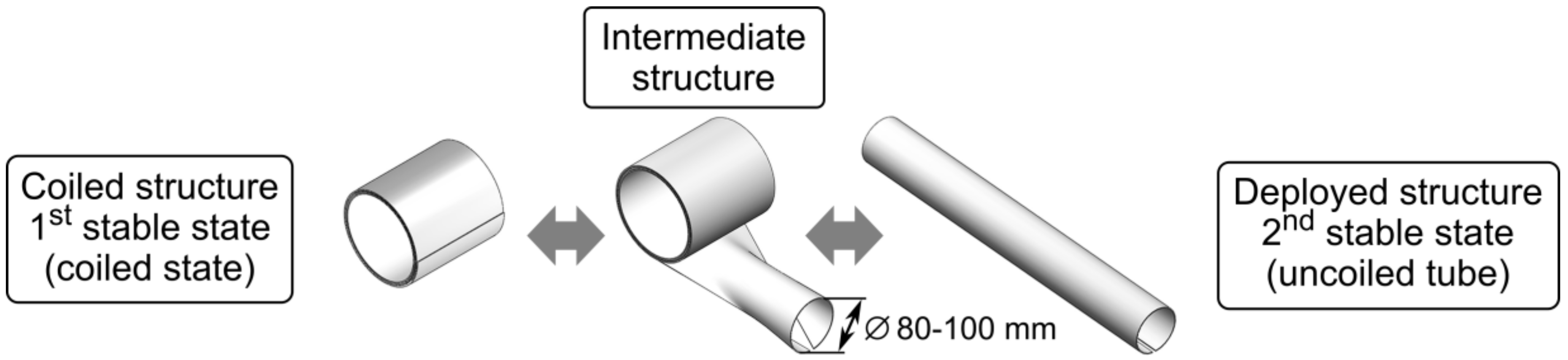
In order to describe the phenomenon of bistability, the semianalytical model needs to cover the whole process of two subsequent bending operations over two different axes in two opposite directions. The metastable states are identified by searching for a minimum of the bending moment resulting from the residual stresses acting in longitudinal and transversal direction of the shell.
As a starting point, an already published model aiming at the production of bistable metallic shells by Kebadze et al. [7] is used. The model introduced now enhances this model by considering bending of already prebended and annealed cylindrical shells over perpendicular axis in opposite direction and gives a more detailed description of the kinematic and isotropic material hardening which are considered.
Contrary to the Kebadze et al. model [
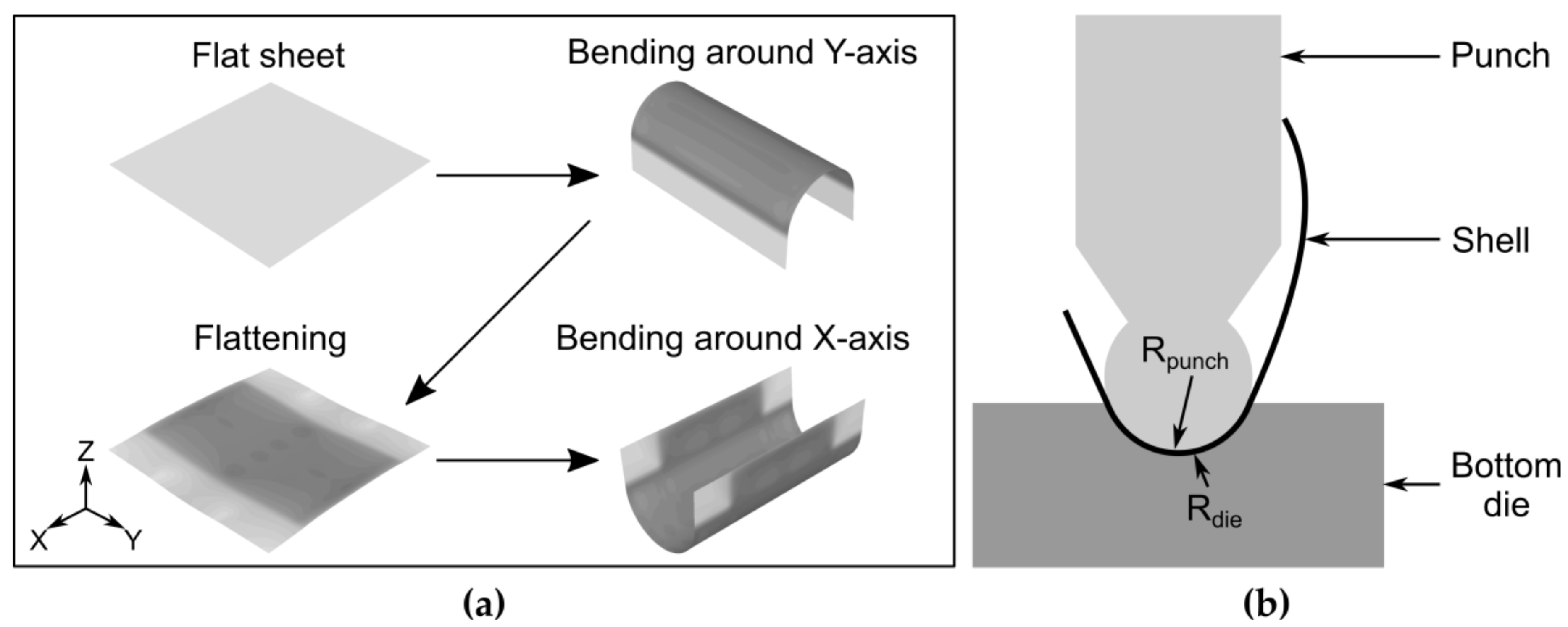
7], in the following paragraphs the model is explained following the production process, starting with pure elastic bending of the flat unbent shell, moving to elastic–plastic bending, first springback after unloading, second bending operation, including elastic and plastic deformation, and final elastic springback. Moreover, for the model verification, a 0.1 mm thick shell of annealed beryllium–copper with an initial yield stress of 650 MPa was used by Kebadze et al. [7]. Along this explanation, equations given by Kebadze et al. [7] are stated as far as they are necessary to understand the general concept. A more detailed description can be found in the publication of Kebadze et al. [7] itself.
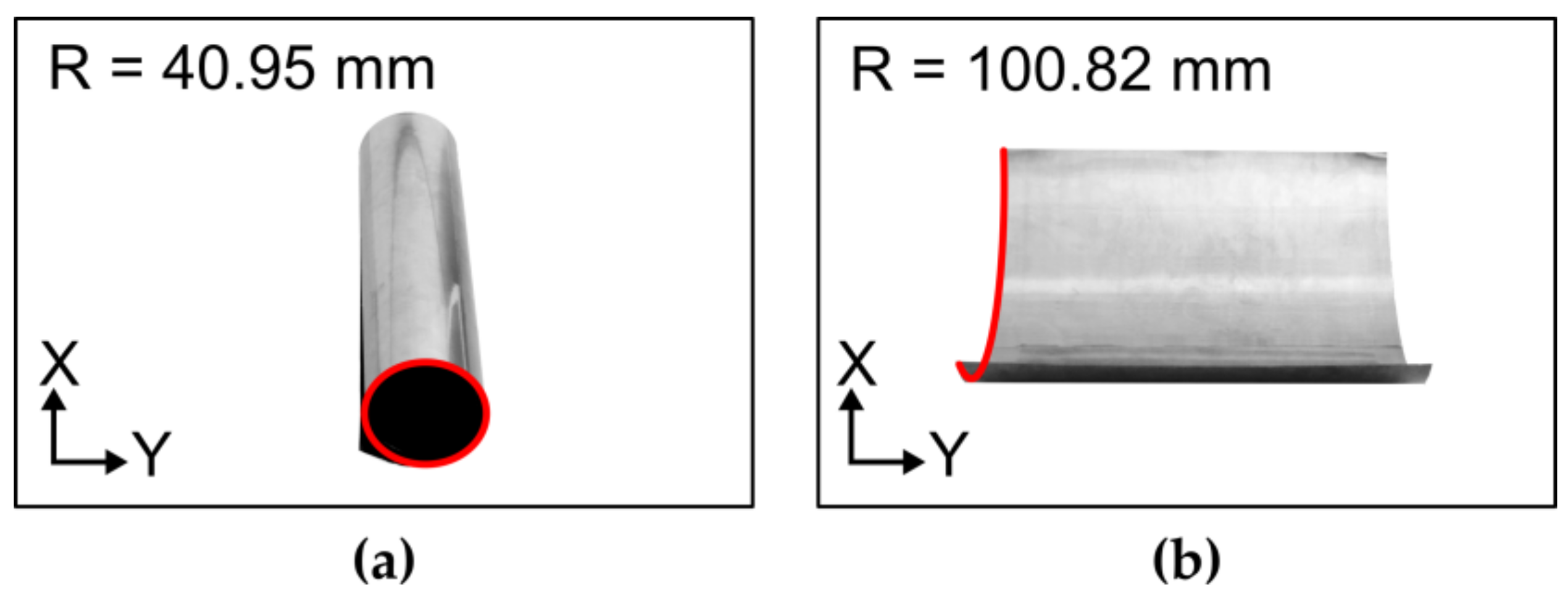
The preliminary experiments of manufacturing bistable metal shells using an incremental die-bending process indicate that in case of equal bending radii in the two consecutive bending operations, the springback radius after the second bending is always smaller than the springback radius after the first bending. This can be attributed to the displacement of the yield locus instead of increasing the yield locus and, therefore, to kinematic hardening. However, after switching between the first and second stable state, the springback radii do not change. Therefore, no plastic deformation occurs during the change between the stable states. Based on these observations, kinematic hardening in the first bending operation followed by isotropic hardening in the second bending operation is assumed. A similar approach is employed by Kebadze et al. [7], who refer to a work of Crisfield [10] regarding details on the calculation scheme. Since this assumption satisfies the experimental observations, it will be applied for the analytical model in a first step.
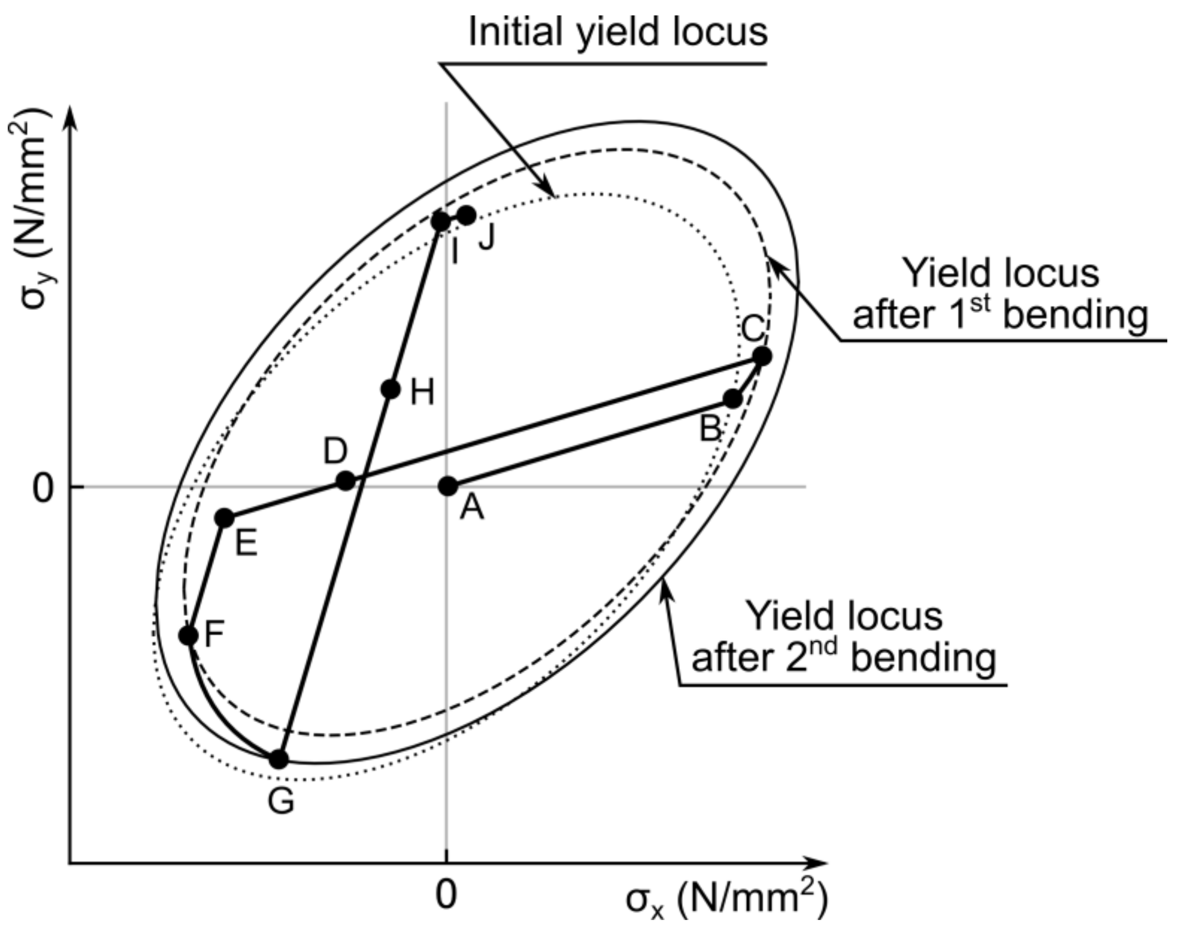
The whole chain of the bending process is depicted by means of the stress state and the von Mises yield criterion in Figure 4. The yield locus represents the stresses on the surface of the shell. Point A corresponds to the unstressed flat shell. After the start of the first bending over the Y-axis, the shell initially deforms elastically until the stress state reaches point B. Subsequently, plastic forming takes place until point C. After the first bending, the shell has the curvature of k1. During plastic forming, kinematic hardening occurs and the yield locus is translated from the original position by an amount equal to the vector of plastic stress accumulated during plastic forming. After plastic forming, the material unloads linearly until point D, which corresponds to the springback configuration with the shell curvature of ksb. After springback, the shell is bended further until the flat state (point E). From the flattened state, the bending over the X-axis starts. This step also consists of elastic deformation until point F and plastic forming until point G. After the second bending, the shell has the curvature of k2. Unlike the first bending, plastic forming at the second bending operation leads to isotropic hardening [7], and the yield locus grows. Point H corresponds to the springback configuration after the second bending operation, which is equal to the first stable state with the shell curvature of k1.geom,y. By bending the shell to the flat geometry (point I) and further bending in the opposite direction over the Y-axis, the second stable state could be achieved at point J with the shell curvature of k2.geom,x. In the next sections, this bending sequence will be described in detail for each single step.
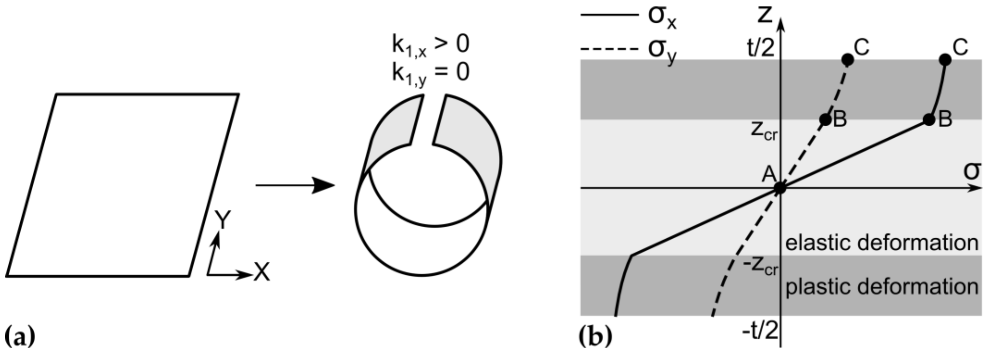
It is defined that after first bending and springback along the Y-axis, the shell curvature is positive (k1,x > 0). After bending the shell in reverse direction along the X-axis (k2,y < 0) and at the first stable state, the curvature has a negative sign (k1.geom,y < 0). At the second stable state, when the shell is bent along the Y-axis, the curvature again has a positive sign (k2.geom,x > 0). Taking this into account, an assessment of the stability of the shell geometry becomes possible. If the first and second geometry have an opposite sign in curvature other than defined, there is no stable geometry along the given axis, and, correspondingly, the shell is not bistable.

2.2.1. Elastic Deformation during the First Bending

The stress state after the first bending σC could be divided into two parts: elastic stresses and plastic stresses (Figure 5b). The starting point of the process is an elastic bending within the first bending operation. In general, stresses and strains are considered in two dimensions according to the above-mentioned assumptions. For means of simplification, a vector notation is used as given in Equation (1).
σ = [ σ x σ y ]   and   ε = [ ε x ε y ]
Due to the assumed similar stress–strain behavior of material under tension and compression, only half of the shell thickness must be taken in account. The stresses on the other half could be assumed the same, but with opposite sign.
Generally, the thickness of the shell at elastic and plastic part is divided into n layers each. Accordingly, the stress state of each layer is calculated subsequently using 2n increments. For this research, a value of n = 200 has been determined to give suitable results.
It is necessary to define the transition from elastic to elastic–plastic bending. Thus, a critical depth measured from the neutral axis can be defined below which the shell does only deform elastically under a given curvature (see Equation (2)).
z c r = σ 0 ( 1 v 2 ) E k 1 1 v + v 2
within this equation, E is the Young’s modulus, k1 is the first bending curvature, v is the Poisson’s ratio, σ0 is the initial yield stress of the material, and z gives the distance from midsurface of the shell. The maximum elastic strain and elastic strain increment follow accordingly and are given in Equations (3) and (4).
ε e l = k 1 z c r
Δ ε e l = [ k 1 · z c r n 0 ]
where n is the number of increments.
The accompanying stresses can be calculated via the material stiffness matrix C as stated in Equations (5) and (6) [7].
σ I , i = C Δ ε e l
C = E 1 ν 2 · [ 1 v v 1 ]

2.2.2. Plastic Forming during the First Bending

In the Kebadze et al. model [7], the stress–strain relationship of the shell was represented as tabular data. In this work, since the transition point between elastic and plastic bending is known, the stresses under bending load are described via the extended Voce equation [11]. Furthermore, the equivalent stress according to the von Mises yield criterion can be calculated utilizing Equation (7) [7].
σ v = σ T A σ 2
where A denotes the auxiliary matrix for the given stress state for pure bending (Equation (8) [7]).
A = [ 2 1 1 2 ]
Knowing the stress state at which plastic forming starts, it is necessary to describe the evolution of the stress state under load. The consistency criterion is applicable in that case and can be written in the form according to Equation (9) [7].
f = σ v σ 0 = σ T A σ 2 σ 0 0
In order to describe the evolution of the yield locus, the so-called strain hardening parameter H should be calculated (Equation (10) [7]). The strain hardening parameter consists of the tangent modulus Et, which gives the slope of the yield locus at a given stress state.
H = E E t E E t
In this work, the tangent modulus is derived by differentiating the extended Voce equation [11] as stated in Equation (11).
E t = σ ( ε p l ) ε p l = θ 0 ( θ 1 ε p l + σ 1 ) e θ 0 ε p l σ 1 σ 1 + θ 1 ( 1 e θ 0 ε p l σ 1 )
where θ0 is the initial hardening rate, θ1 is the asymptotic hardening rate, and (σ0 + σ1) is the back-extrapolated yield stress, with σ0 as the initial yield stress. After plastic forming starts, the stresses acting on the material can be calculated with the help of the material tangent stiffness matrix as given in Equation (12) [7].
C t = C ( I a a T C a T C a + H )
within this equation, I denotes the 2 × 2 identity matrix, and a is the normal vector to the yield surface (see Equation (13) [7]):
a = A σ 2 σ v
Along plastic forming, the direction of the tangent to the yield locus changes along with the evolving stress state. Thus, it is necessary to conduct an iterative calculation of the change of the yield locus. Therefore, the total plastic strain is divided in n increments. The plastic strain increment can be calculated via Equation (14):
Δ ε p l = ( t / 2 z c r ) · k 1 n
where t is the thickness of the shell. The given stress increment and the total stress under load can be calculated according to Equations (15) and (16) [7]:
Δ σ p l = C t Δ ε p l
σ I , i = σ I , i 1 + Δ σ p l
The plastic stress distribution after first bending is shown in Figure 5b. The evolution of the stress state is assumed to be caused by kinematic hardening. Thus, the evolution of the stress state in direction of the normal to the tangent at the yield locus is imposed as a shift of the yield locus from the origin of the stress space. This way, the back stress evolving during kinematic hardening is equal to the vector of plastic stress accumulated during plastic forming (which is used as well in the work of Kebadze et al. [7]). Thus, kinematic hardening can be described without using material-dependent coefficients.

2.2.3. First Elastic Springback

The shell is in a mechanical equilibrium if one of the resulting bending moments per unit length, induced by the residual stresses, is close to zero. The specific bending moments can be calculated as given in Equation (17) [12].
( m x m y ) = t 2 t 2 ( σ x ( z ) σ y ( z ) ) z d z
within this equation, z gives the material thickness, mx and my are the resultant bending moments per unit length in the unit Nmm/mm, and σx(z) and σy(z) are the residual stress distributions along the given axes. In order to determine the remaining curvature after springback, the linear relationship between bending moment and resulting shell curvature [12] can be applied according to Equation (18) [13]:
m k = 1 3 E ( t / 2 ) 3 ( 1 ν 2 )
where k is the shell curvature and m is the resultant bending moment per unit length. Assuming that curvature of flattened shell (kE,x) and bending moments along X-axis at springback curvature (mD,x) are equal to zero, the springback curvature can be calculated according to Equation (19).
k s b , x = k D , x = m E , x · 3 ( 1 ν 2 ) E ( t / 2 ) 3
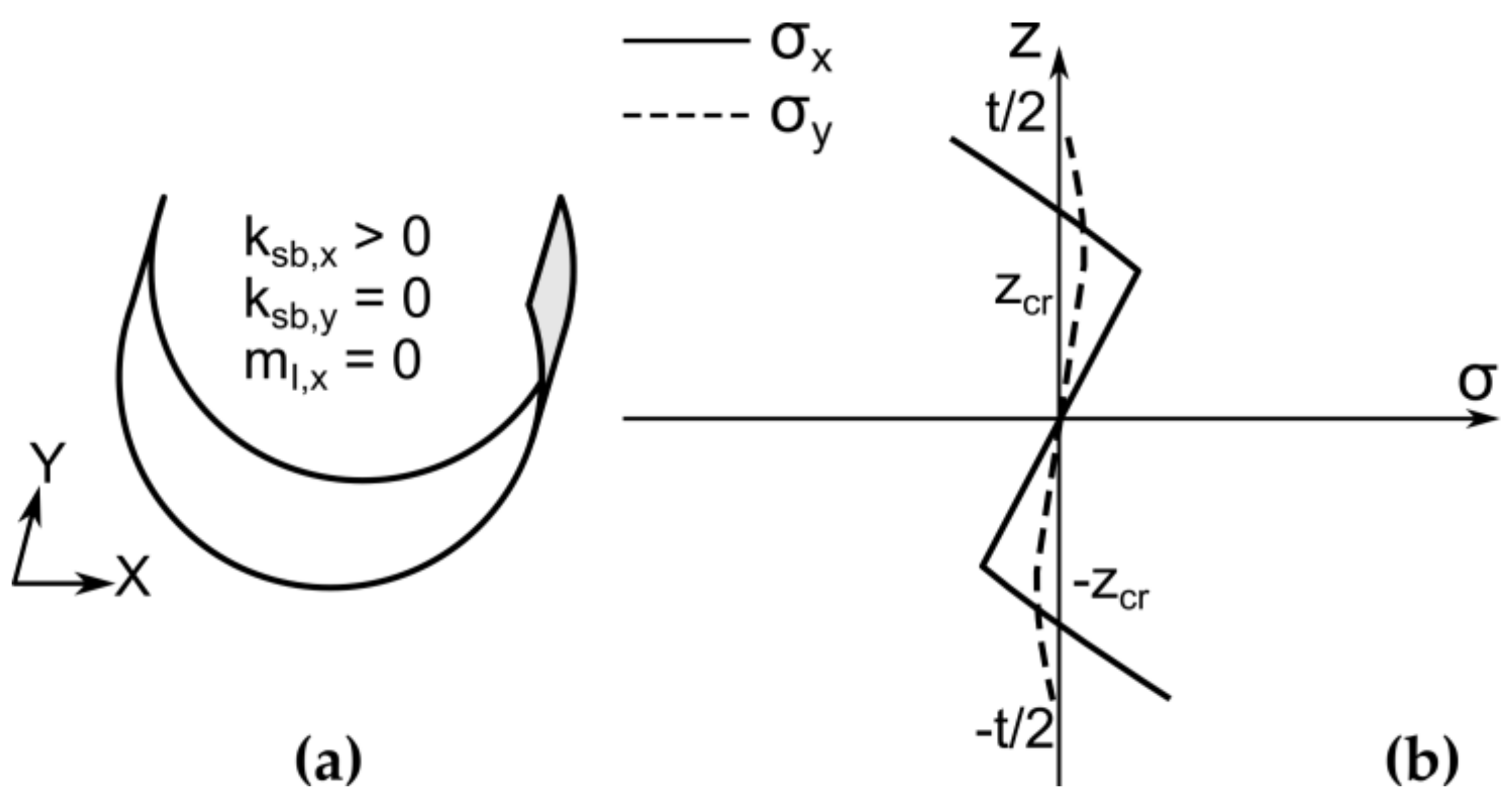
The shell geometry and stress distribution after first springback are shown in Figure 6.

2.2.4. Elastic Bending in the Reverse Direction

First of all, the stress distribution for the flattened shell should be calculated. For this purpose, the elastic stresses calculated for bending of the shell by curvature k1 should be subtracted from the stresses after first bending (Equation (20)):
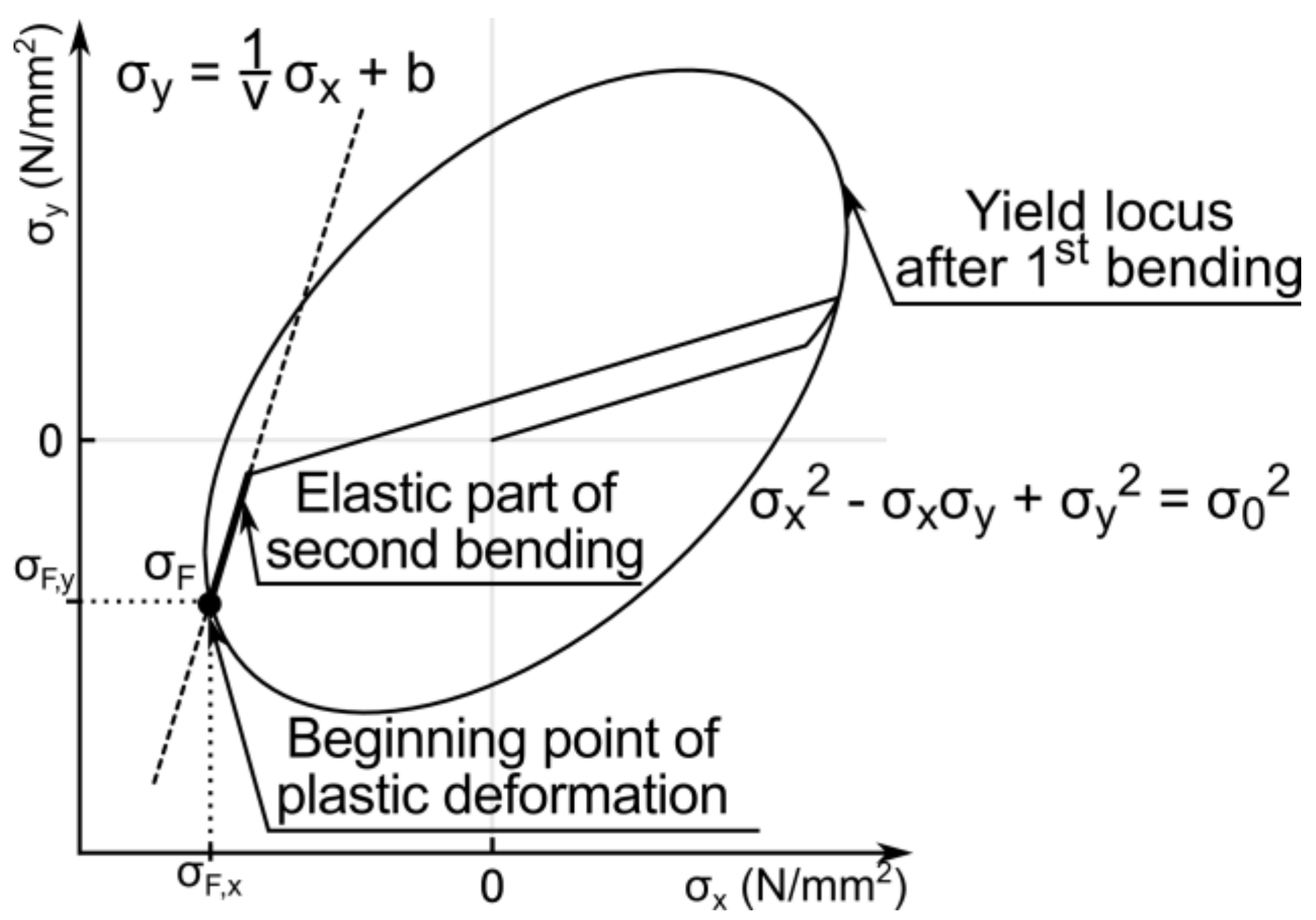
σ E , i = σ C , i z i k 1 C
Afterwards, the x and y components of critical stress values, at which the plastic deformation starts (σF), can be determined by solving a system of two equations (Equation (21)):
{ σ x 2 σ x σ y + σ y 2 = σ 0 2 σ y = 1 v σ x + b
where b is the offset of the elastic part line relative to the Y-axis.
The curvature at which plastic forming begins can be found using Equation (22):
k F = ( σ F σ E ) · C 1 t / 2
Figure 7 shows the determination of the starting point of plastic deformation at the yield surface.

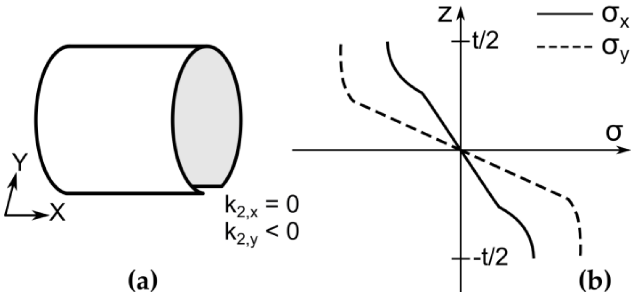
2.2.5. Plastic Bending in the Reverse Direction

Plastic deformation during the second bending can be calculated using the approach from Section 2.2.2. The shell geometry and stress distribution along the shell thickness after the second bending are shown in Figure 8.

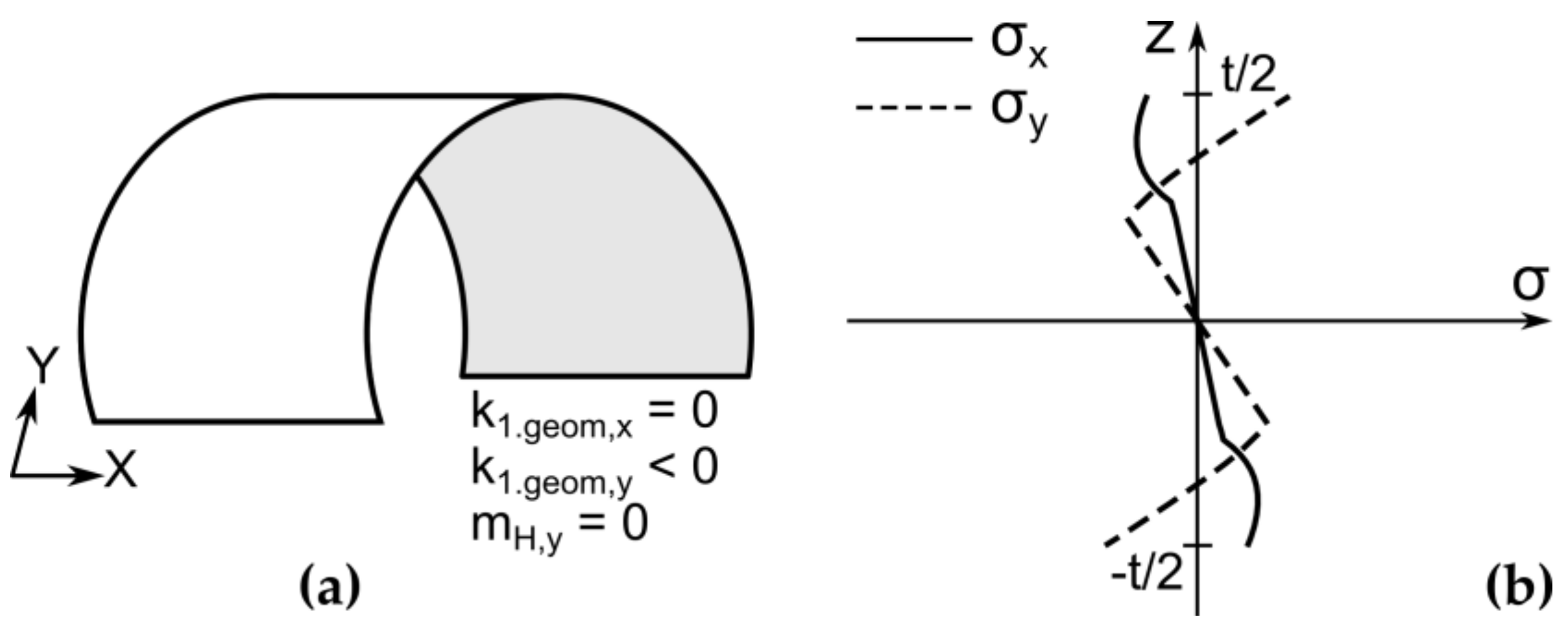
2.2.6. Elastic Springback and the First Stable State

The curvature and the stress distribution of the first stable state can be calculated with the help of Equation (23).
k 1. g e o m , y = m I , y · 3 ( 1 ν 2 ) E ( t / 2 ) 3
where k1.geom,y is the curvature of the first stable state and mI,y is the moment along the Y-axis at the flattened shell after the second bending. The shell geometry and stress distribution at first stable state are shown in Figure 9.

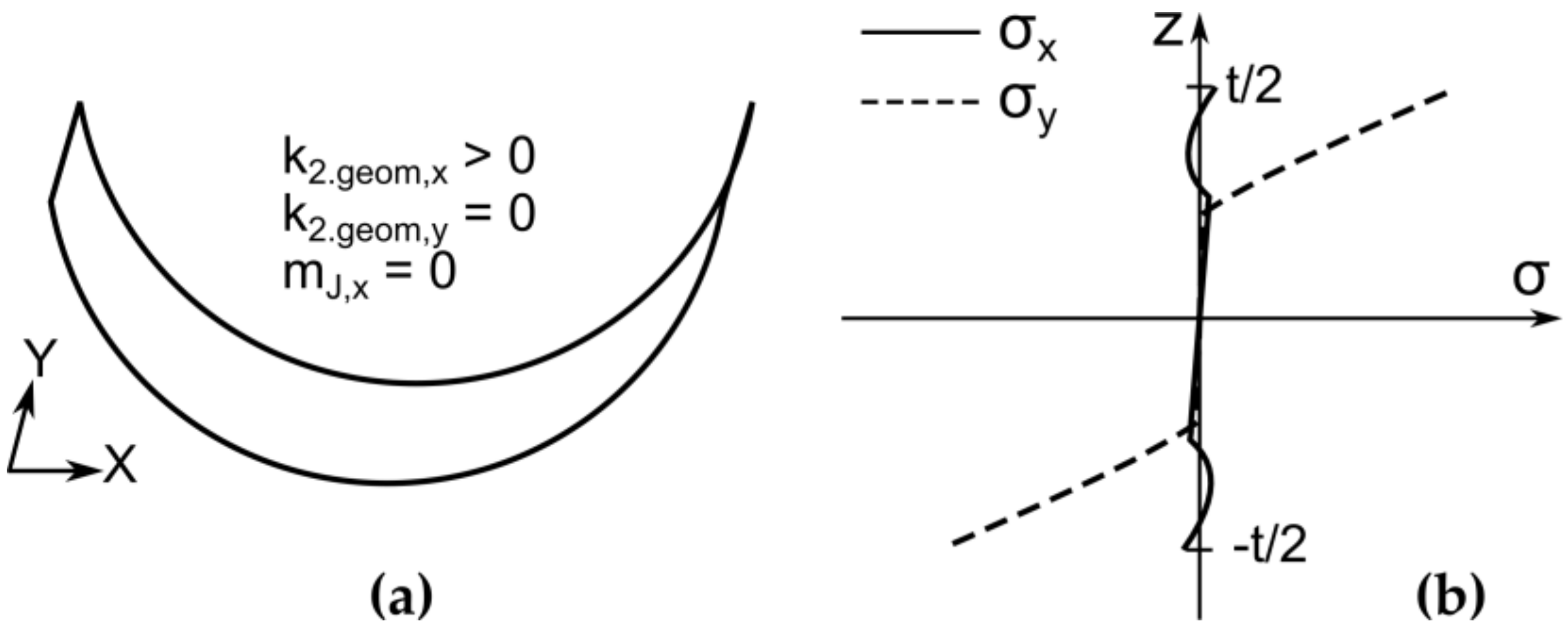
2.2.7. Second Stable State

The curvature and the stress distribution of the first stable state can be calculated with the help of Equation (24).
k 2. g e o m , x = m I , x · 3 ( 1 ν 2 ) E ( t / 2 ) 3
where k2.geom,x is the curvature of the first stable state and mI,x is the moment along the Y-axis at the flattened shell after the second bending. The shell geometry and stress distribution at second stable state are shown in Figure 10.

3. Results and Discussion

With the help of the semianalytical model, the examination of the shell bistability regarding the bending radii combinations R1 and R2 was performed. The model study was performed at bending radii sequences of R1 = {6, …, 12} mm and R2 = {6, …, 12} mm with a step size of 0.1 mm. The semianalytical model was calculated using the software Python. The used material data of steel grade 1.1274 (AISI 1095) is taken from [9] and summarized together with the constants of the extended Voce equation [9] in Table 1.
Here, θ0 is the initial hardening rate, θ1 is the asymptotic hardening rate, and (σ0 + σ1) is the back-extrapolated yield stress, with σ0 as the initial yield stress.
The experimental study was performed for a bending radii sequence R1 = {6, 7, 8, 10} mm and R2 = {6, 7, 8, 10} mm and has already been partially published in [9]. In the following sections, different features of the shell will be discussed. Firstly, the bistability properties regardless of the realized curvature radii will be compared. Thereafter, the experimental and calculated curvature radii of shells at stable states will be studied. Finally, the calculated residual stress distribution for a bistable, fully closed shell, produced with bending radii combination R1 = R2 = 6 mm, will be compared with an experimentally measured distribution.

3.1. Bistability of the Shell

The results regarding the achieved bistability are shown in Figure 11. Only for the bending combinations (R1 = 7 mm, R2 = 6 mm) and (R1 = 8 mm, R2 = 7 mm), experiments and semianalytical calculations do not coincide. Both combinations are situated almost at the boundary, separating bistable and monostable shells. Nevertheless, a more accurate yield stress determination could help to solve this issue.

3.2. Radii of Stable Geometries

As mentioned before, during the experiments, shells with a size of 300 × 300 mm2 were incrementally bended. Opposite to experiments, in the semianalytical model, the size of the shell is considered as infinite and there is only one single bending around each axis. Despite this difference, a comparison of experiment and model regarding the final curvatures is done. In this way, the general tendencies concerning the influence of the bending radii on the resulting curvature could be compared. In Figure 12, the shell curvatures of first (a) and second (b) stable states depending on the second bending radius R2 at a fixed first bending radius R1 = 6 mm are depicted. It can be seen that the calculated results are in good agreement with the experimental values, despite the fact that calculated radii are higher than the experimental ones. It should also be mentioned that only for a bending radii combination of R1 = R2 = 6 mm, a fully closed bistable shell was produced. Due to the shell width of 300 mm, the maximal radius of a fully closed shell is equal to 47.75 mm, which is mentioned in Figure 12, Figure 13, Figure 14 and Figure 15 by a grey horizontal line. As the second bending radius increases, the curvature of the first stable state increases and the curvature of the second stable state decreases, both in experiment and in model.
Figure 13 depicts the curvatures for both stable states produced with a first bending radius of R1 = 7 mm. As was mentioned before, the main difference between calculated and experimental results is derived for the combination of (R1 = 7 mm, R2 = 6 mm). During experiments, the bistability was not achieved. For this part of the parameter study, it should be also noted that the calculated shell geometries have smaller curvature radii for almost all bending radii combinations. None of the experiments reached a fully closed curvature of bistable shell. In general, the curvature of the first stable state increases and the curvature of the second stable state decreases by increasing the second bending radius.
Figure 14 depicts radii of stable shell structures produced with a first bending radius of R1 = 8 mm. The bistable behavior of the shell structure has been achieved during the experiments only for a bending radii of R2 = 8 mm and R2 = 10 mm. At the same time, the model predicts that the bistable properties will not be achieved for R2 = 6 mm. However, the radii of curvature for both stable states are too high to achieve a fully closed shape of bistable shell.
Figure 15 depicts radii of stable shell structures produced with a first bending radius of R1 = 10 mm. The bistable behavior of the shell structure has been achieved during the experiments and model calculation only for a bending radii combination of R1 = R2 = 10 mm. This could be seen also in Figure 15b, where only one curvature of second stable state for experimental results is marked. However, the radii of curvature for both stable states are too high to achieve a fully closed shape. For the bending radii combinations with R2 < 10 mm, only small deviations between calculated and produced first stable states radii can be found. However, for the bending radii combination of R1 = R2 = 10 mm, a huge difference between the model and the experiment is obvious. The reason for this difference could be the proximity of the maximum plastic stress at this bending curvature to the initial yield stress of the material.

3.3. Residual Stress Distribution

For the verification of the model, the calculated residual stress distribution along the shell thickness is compared to a measurement of residual stresses done by using the X-ray diffraction method. The measurements were carried out with the friendly support of the Leibniz Institute for Materials Engineering (IWT). Considering the change of atomic interplanar distances under the influence of residual stresses, the X-ray diffraction method could measure these deviations and, accordingly, calculate the residual stresses [14]. The measurements were done for the aforementioned fully closed bistable shell produced with bending radii of R1 = R2 = 6 mm. Stress values were measured from the surface until the middle of the shell with the step size of 0.02 mm for both stable geometries. The measured results are given in Figure 16 and show a good qualitative agreement between the model and the experimental results. Nevertheless, there are still deviations in the absolute values.

4. Conclusions

The aim of the present work was to develop a semianalytical model for the investigation of bistable properties and the final curvatures of metallic shells. For this purpose, a model using a combination of isotropic and kinematic hardening was used to identify suitable bending radii combinations to realize bistability. Experimental results have suggested that the first bending operation should be described by kinematic hardening, whereas for the second one, isotropic hardening can be assumed. Future work will be done to clarify this assumption, which might be caused by residual stresses in the starting material and the orientation of the bending axis referring to the rolling direction of the initial material.
Due to the short calculation time compared to an FEM simulation, the model can be used for investigating the influence of material properties and process parameters on the bistability properties of metallic shells.
For the model verification, an incremental die-bending parameter study was done. The calculated and experimental results are in good agreement regarding bistability properties of the shell, despite inconsistent results at the boundary between bistable and monostable shell properties. The residual stress measurement, done by X-ray diffraction analysis, shows good qualitative correspondence between calculated and measured residual stresses of the shell, obtained by a bending radii combination of R1 = R2 = 6 mm. Moreover, a fully closed, metallic bistable shell was achieved within experiments with this bending radii combination.
The new semianalytical model allows for a precalculation of promising process sequences and corresponding bending radii for different metallic materials and shell thicknesses. The results obtained by calculations and experiments show that a bistable shell property, as well as a fully closed geometry, could only be achieved by using small radii combinations.

Author Contributions

Conceptualization, P.P., M.T., M.G. and G.H.; Methodology, P.P. and M.G.; Validation, P.P.; Investigation, P.P.; Writing—Original Draft Preparation, P.P.; Writing—Review and Editing, M.T., M.G., G.H. and P.P.; Visualization, P.P.; Software, P.P.; Project Administration, G.H.; Funding Acquisition, G.H.

Funding

This research was funded by the German Research Foundation (Deutsche Forschungsgemeinschaft) within the priority program SPP 2013 “The utilization of residual stresses induced by metal forming” (DFG, project HI 790/57-1).

Acknowledgments

The authors would like to thank the Leibniz Institute for Materials Engineering (IWT) for conducting X-ray diffraction measurements of residual stresses and the Steel Institute (IEHK) of the RWTH Aachen University for ultrasonic measurement of elastic modulus.

Conflicts of Interest

The authors declare no conflict of interest.

Nomenclature

anormal vector to the yield surface
Cmaterial stiffness matrix
Ctmaterial tangent stiffness matrix
EYoung’s modulus
Ettangent modulus
fyield function
Hhardening parameter
Iidentity matrix
kcurvature of cylindrical surface
k1, k2first and second bending curvatures, respectively
mresultant bending moments per unit length
nnumber of increments
Rbending radius
tshell thickness
zthrough-thickness coordinate measured from mid plane
zcrcritical depth
εvector of principal strain components
νPoisson’s ratio
σvector of principal stress components
σistress vector at step i
σvvon Mises effective stress
σ0yield stress in pure tension
Subscripts
()elelastic
()plplastic
(){A…J}at bending process point {A…J}
()j.geomat j stable state
Operators
()Ttranspose of the matrix
()-1inverse of the matrix
Δchange between two consecutive steps

References

  1. Pellegrino, S. Deployable Structures; Springer: Wien, Austria, 2001; pp. 99–111. ISBN 978-3-7091-2584-7. [Google Scholar]
  2. Groskopfs, E. Storable Tubular Extensible Member Device. U.S. Patent US3434674A, 25 March 1969. [Google Scholar]
  3. Knott, G.; Viquerat, A. Curved bistable composite slit tubes with positive Gaussian curvature. AIAA J. 2018, 56, 1679–1688. [Google Scholar] [CrossRef]
  4. Galletly, D.; Guest, S. Bistable composite slit tubes. I. A beam model. Int. J. Solids Struct. 2004, 41, 4517–4533. [Google Scholar] [CrossRef]
  5. Galletly, D.; Guest, S. Bistable composite slit tubes. II. A shell model. Int. J. Solids Struct. 2004, 41, 4503–4516. [Google Scholar] [CrossRef]
  6. He, X. Bi-stable character of laminated cylindrical shells. Procedia Eng. 2011, 14, 616–621. [Google Scholar] [CrossRef]
  7. Kebadze, E.; Guest, S.; Pellegrino, S. Bistable prestressed shell structures. Int. J. Solids Struct. 2004, 41, 2801–2820. [Google Scholar] [CrossRef]
  8. Norman, A.; Seffen, K.; Guest, S. Multistable corrugated shells. Proc. R. Soc. A 2008, 464, 1653–1672. [Google Scholar] [CrossRef]
  9. Pavliuchenko, P.; Bremen, T.; Grüber, M.; Teller, M.; Hirt, G. Production of bistable fully closed metallic shells by introducing residual stresses during bending processes. Prod. Eng. Res. Dev. 2019, 1–9. [Google Scholar] [CrossRef]
  10. Crisfield, M. Non-Linear Finite Element Analysis of Solids and Structures, Volume 1: Essentials; Wiley: Hoboken, NJ, USA, 1996; ISBN 978-0471970590. [Google Scholar]
  11. Tomé, C.; Maudlin, P.; Lebensohn, R.; Kaschner, G. Mechanical response of zirconium—I. derivation of a polycrystal constitutive law and finite element analysis. Acta Mater. 2001, 49, 3085–3096. [Google Scholar] [CrossRef]
  12. Ghosh, A. Process design for shell forming. In ASM Handbook Volume 14B: Metalworking: Shell Forming; Semiatin, S., Ed.; ASM International: Materials Park, OH, USA, 2006; pp. 707–826. ISBN 978-0-87170-710-9. [Google Scholar]
  13. Patel, S.; Lal, R.; Dwivedi, J.; Singh, V. Springback analysis in shell metal forming using modified Ludwik stress-strain relation. ISRN Mech. Eng. 2013, 2013, 1–11. [Google Scholar] [CrossRef]
  14. Ruud, C. Measurement of residual stresses. In Handbook of Residual Stress and Deformation of Steel; Totten, G., Inoue, T., Howes, M., Eds.; ASM International: Materials Park, OH, USA, 2002; pp. 99–117. ISBN 978-0-87170-729-1. [Google Scholar]
Figure 1. Schematic representation of a fully closed bistable shell.
Jmmp 03 00022 g001
Figure 2. Scheme of the production process of bistable shells (a) and schematic representation of experimental setup (b) [9].
Jmmp 03 00022 g002
Figure 3. Bistable tube (produced by incremental die-bending with R1 = R2 = 6 mm) in deployed state as the first stable state (a) and (partially) folded configuration as the second stable state (b) [9].
Jmmp 03 00022 g003
Figure 4. Yield locus displacement and stress path during bending operations.
Jmmp 03 00022 g004
Figure 5. Shell geometry (a) and stress distribution along the shell thickness (b) after first bending.
Jmmp 03 00022 g005
Figure 6. Shell geometry (a) and stress distribution (b) after first springback.
Jmmp 03 00022 g006
Figure 7. Determination of the starting point of plastic deformation during second bending.
Jmmp 03 00022 g007
Figure 8. Shell geometry (a) and stress distribution along the shell thickness (b) after second bending.
Jmmp 03 00022 g008
Figure 9. Shell geometry (a) and stress distribution along the shell thickness (b) at first stable state.
Jmmp 03 00022 g009
Figure 10. Shell geometry (a) and stress distribution along the shell thickness (b) at second stable state.
Jmmp 03 00022 g010
Figure 11. Results regarding bistability for different combinations of bending radii obtained by experiments and semianalytical calculation.
Jmmp 03 00022 g011
Figure 12. Radii of curvature for first (a) and second (b) stable state after first bending operation with a radius R1 = 6 mm and various second bending radii R2.
Jmmp 03 00022 g012
Figure 13. Radii of curvature for first (a) and second (b) stable state after first bending operation with a radius R1 = 7 mm and various second bending radii R2.
Jmmp 03 00022 g013
Figure 14. Radii of curvature for first (a) and second (b) stable state after first bending operation with a radius R1 = 8 mm and various second bending radii R2.
Jmmp 03 00022 g014
Figure 15. Radii of curvature for first (a) and second (b) stable state after first bending operation with a radius R1 = 10 mm and various second bending radii R2.
Jmmp 03 00022 g015
Figure 16. Residual stresses over the shell cross section at first (a) and second (b) stable state (R1 = R2 = 6 mm).
Jmmp 03 00022 g016
Table 1. Averaged properties of steel 1.1274 obtained from quasi-static tensile tests and values of constants for the extended Voce equation [9].
Young’s Modulus, EInitial Yield Stress, σ0σ1θ0θ1
198,540 MPa1685 MPa128.9 MPa32,639.8 MPa4863.4 MPa

