1. Introduction
Machine tools with three, five or more axes are now equipped with touch trigger probes to accomplish metrology tasks such as tool path re-planning [
1] or setup location and finishing path correction for the workpieces and even to evaluate the conformity of the finished machined parts [
2]. The machine tool accuracy directly affects its ability to be used for such tasks. Accuracy is defined in the VIM (International Vocabulary of Metrology) as “closeness of agreement between a measured quantity value and a true quantity value of a measurand’’ [
3] thus that it includes both systematic and so-called non-repeatable effects. A similar approach is used in the ISO (International Organization for Standardization) standard on machine tool accuracy [
4].
On coordinate measuring machines, a probe head with two rotary axes is used to gain access to features on complex parts. The resulting change in the position of the stylus tip with respect to the machine foundation is handled by calibrating the change in this position through the probing of a reference ball at a fixed position in the machine base frame. A similar approach could be adopted on a five-axis machine, but it is not probably due to the limited available space on the workpiece table. Instead, the approach here is to rely on the measured angular positions of the rotary axes to perform the computation of the stylus tip in the workpiece table frame. Performing such calculation using a nominal, error free machine model will likely result in coordinates of a similar level of accuracy as the machine tool itself. Improvement in the computed coordinates, as was done on coordinate measuring machines [
5,
6], is possible through the use of a rigid body kinematic model incorporating known machine errors. Using the mathematical models to simulate the machine tool geometry is the main concept to compensate the error parameters.
A variety of approaches have been proposed to acquire the machine error parameters [
7,
8], using touch trigger probes [
9], scanning probes, ball bars [
10], laser interferometers, and laser trackers are some methods which have been applied to this task. A pseudo 3D grid configured from a kinematically relocated calibrated 2D ball plate [
11] was proposed for testing and calibrating machine tools but it was used for a 3-axis vertical machine. By increasing the number of machine axes, with rotary axes, the machine geometry becomes more complex and the number of error sources increases. Assessing the out of sphericity by probing 25 points on a precise ball mounted on the machine tool table, for various rotary axes indexations was used to assess the coordinate measurement accuracy of a five-axes machine tool before and after considering the machine’s error parameters [
12]. However, no traceability is provided to the meter. The ball dome artefact, proposed by Mayer and Hashemi [
13] is made of Invar, to eliminate the thermal effects deformation, was developed to estimate a five-axis machine tool metrology performance. Calibrating the coordinates of the balls to obtain reference values provides this traceability.
Machining a part and then measuring it by a coordinate measuring machine (CMM) is a common industrial method to check the accuracy of a machine but it is not only an expensive and time consuming method but also it is just applicable to the machining mode and it is not useful for machine evaluation in the coordinate measuring mode [
14,
15].
In this paper, an alternative calibration verification method is defined for a five-axis machine center when all five axes contribute to the measurement. First, the SAMBA method for machine calibration [
16] is briefly explained. Then the mathematical model used to compensate the machine readings using its topology and error parameters is presented. It is followed by the SAMBA experimental probing procedure, which produces the calibrated machine stylus tip offsets. Finally, the newly designed ball dome artefact is used to validate the SAMBA calibrated model for a five-axis machine tool used as a five-axis coordinate measuring machine.
2. SAMBA Calibration Method
The machine tool error parameters are gathered using the scale and master balls artefact (SAMBA) method, which consists in probing special artefacts and using the raw probing data to estimate the machine error parameters as an indirect method through a mathematical model. The SAMBA hardware part is composed of a reconfigurable uncalibrated master ball artefact (RUMBA) and a length standard; all mounted on the machine table. The processing of the raw probing data allows estimating the machine errors parameters, the artefact positions, the stylus tip coordinates (as the tool), and the volumetric errors.
Let the topology of the machine be wCBXFZYSt wherein the workpiece branch includes C-, B- and X-axis and the tool branch includes the Z- and Y-axis and the spindle. The two branches are linked by the foundation frame F. W, S and t stand for the workpiece, the spindle and the tool, respectively. The nominal kinematics of the machine is
where the first parenthesis is the homogeneous transformation matrix (HTM) of the workpiece to the frame and the second one is the HTM of the tool to the frame. However, the kinematics of a real machine contains the errors as follows:
where
X0,
Y0,
Z0,
B0,
C0,
wn,
S, and
tn are the nominal joint positions.
X′
0,
Y′
0,
Z′
0,
B′
0, and,
C′
0 are the actual joint positions before movement. X, Y, Z, B, and C describe the nominal motion and
X′,
Y′,
Z′,
B′,
C′,
wa,
S′, and
ta describe the error motions. The erroneous five-axis machine requires 30 intra-axis errors (error motions) and eight inter-axis errors (axis location errors). Considering the two spindle lateral offsets and the three linear axis scale gain errors add another five parameters. However, different error models have been studied which typically contain all or a few of those errors [
16,
17]. The “13” machine error model, describing the erroneous machine, is studied in this paper due to its advantages such as short measuring time and simple indexation design. This error model consists of eight axis location errors, the two spindle offsets, and the three linear gains errors [
16]. The model mainly contains inter-axis errors. However, the three linear gain errors, EXX1, EYY1 and EXX1 associated with the intra-axis errors EXX, EYY, and EZZ, respectively, are significant error sources and thus they are added to the model.
The strategy of SAMBA method is applied wherein B- and C-axis fully rotate. By releasing ball positions, which are not accessible, by the touch probe in some indexations, a number of joint positions are achieved for which the following Jacobian is constructed
where
EV is the volumetric error,
J is the Jacobian and
EP contains the machine error parameters. Provided a well-conditioned system a least square solution is found via the pseudo inverse
where
J† is the pseudo-inverse of
J. The main steps of the SAMBA method are as follows: machine error model selection, artefact selection, indexation design (relative positions of the rotary axes) and verification, probing G-code generation, probing on the real machine tool and data processing.
3. SAMBA Test on Experimental Machine Tool
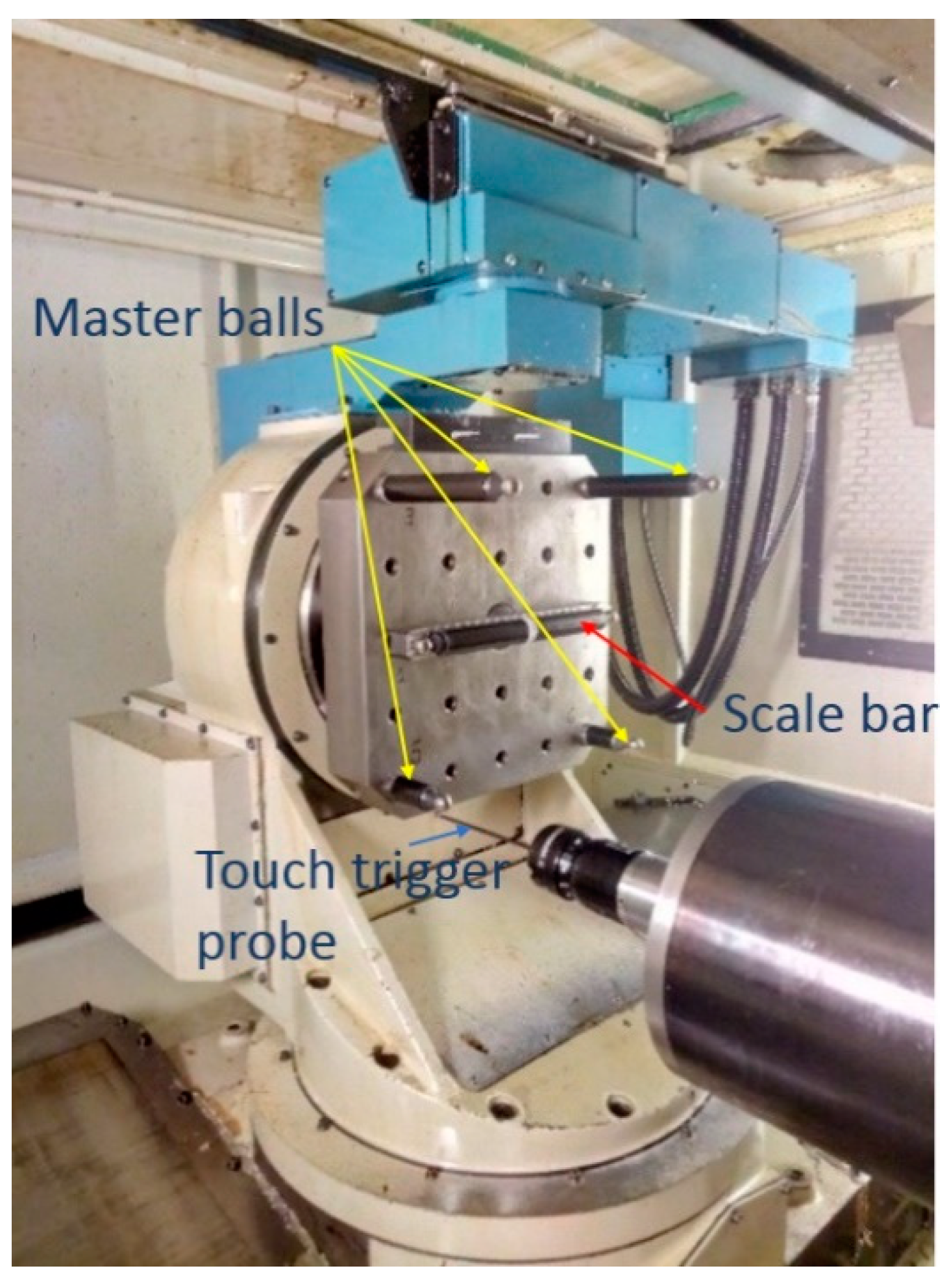
Figure 1 shows the probing process with an MP700 Renishaw touch trigger probe of the SAMBA method of four accessible master balls and one scale bar artefact installed on the pallet of the HU40-T machine tool and
Table 1 presents the nominal position of the ball centers. The tough trigger probe contacts the workpiece, which triggers the acquisition of the X-, Y- and Z- axis readings. The master ball is always measured twice. For each of these measurements, the master ball artefact is measured with fast and slow probing speed. The first measurement is to get a better estimate of the ball position, before re-measuring it using this new center as a target for the probing. For the second measurement, the probing approaches are adjusted to ensure the spherical surface is touched with an approach close to the local surface normal. The second master ball artefact positions are recorded.
For each measurement, the same probing strategy is applied. It is probed at +45 and −135 degree, to get a plane for the measurements at –45 and +135 degree. Then a point on the pole is taken. A simple geometric calculation is used to estimate the centre. For the SAMBA probing process, the Renishaw MP700 touch trigger probe has negligible pre-travel variation errors (0.25 um) thus it is not compensated.
A total of 109 balls probing for 32 angular axes indexations pairs are recorded from which 13 machine error parameters, six balls coordinates and three tool coordinates are estimated. Axes indexations include 0°, ±10°, ±30°, ±60°, and ±90° for the B-axis; from zero to 360° and reverse for the C-axis by 90° steps and from zero to 360° for the spindle axis by 90° steps. During the measurement, the laboratory temperature varied between 21 and 23 °C and the machine tool is started in the cold condition before each measurement. The test was repeated 11 times on different days over a two month period.
4. Machine Tool Estimated Error Parameters
The estimated machine tool error parameters obtained from the SAMBA method are listed in
Table 2.
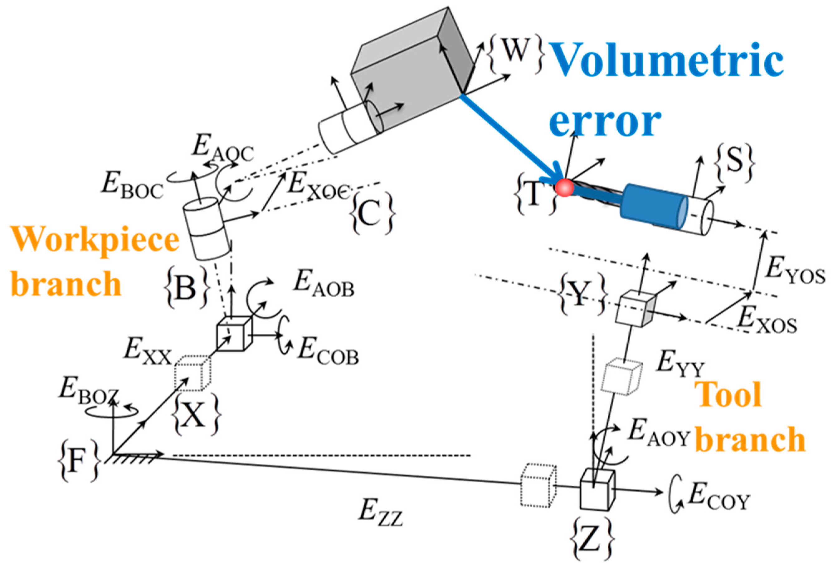
Figure 2 illustrates the error terms in the machine kinematic chain.
5. The Ball Dome Artefact
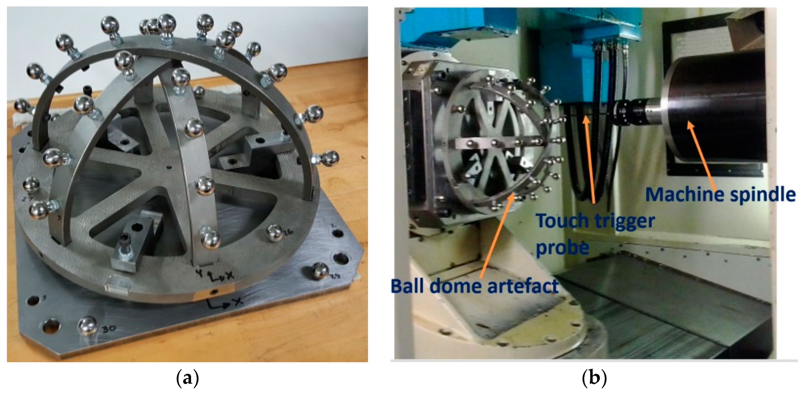
In order to evaluate the machine metrology performance across the entire machine workspace, the maximum number of artefact balls should be accessible for probing for a broad range of angular axis positions. The ball dome artefact structure includes three semi-circular arcs attached together at their mid-point, with both ends fixed to a base ring. The result is a quasi-hemispherical structure holding 25 balls. In addition, there are three balls on the base ring and four balls on the base plate, which provide stable points to define a reference coordinate system. This design allows testing the machine for the full range of rotary axis motion. On this machine tool, the B-axis and C-axis rotation range are –90° to +90° and 0° to 360° respectively. The ball dome artefact is shown in
Figure 3. To limit thermal effects the artefact structure is made of Invar. The measurement repeatability is affected by the clamping force that is applied to hold the artefact on the base plate, and by elastic deformation caused by a changing gravity vector. The reported measurement repeatability for clamping and gravity deflection was on average of the order of 0.6 and 6.5 µm respectively [
13]. The measurement uncertainty for the artefact ball center once mounted on the machine tool is also reported at 5.3 µm (k = 2) [
13].
6. Ball Dome Probing
The ball dome artefact is used to evaluate the machine tool metrology performance with and without the machine calibration. The artefact balls coordinates were measured to an uncertainty of 5.3 µm;
Table 3 lists the measured coordinates. The artefact then is probed on the machine tool. The machine measured ball center coordinates in the machine table frame are calculated using the axis position readings and either the nominal model or the calibrated one, Equation (1). Then they are compared to the reference artefact coordinates. Because coordinate metrology generally requires accessing some features from different angles, the artefact should be probed at various machine indexations to ensure that different rotary axes positions are involved in the measurement process. The ball dome artefact is probed in 24 different machine rotary axes indexations, from −90° to +90° for the B axis and from 0° to 360° for the C axis. At each indexation, the maximum numbers of balls, which are accessible for the probing tool, are measured. A total of 613 ball centers were measured in about 15 h. All the other accessible balls centers are measured once at each pair of rotary axes indexation,
7. Stylus Tip Offsets Calculation
On a five-axis machine tool, there will be a situation when measurements are taken at different rotary axes positions are combined to analyse particular geometric characteristics of the workpiece. In such cases, the stylus tip coordinates are needed. These coordinates can be obtained using different approaches yielding different quality of results. In addition, the machine’s own geometry, as for a coordinate measuring machine, needs to be calibrated and compensated. However, most machine tools are not geometrically calibrated. In this section, various ways to calibrate the stylus tip offsets and the machine geometry are presented. The ball dome is then used as a reference to evaluate the effectiveness of the calibrated models. One of the parameters studied is the effect of the stylus tip offsets. The term stylus tip offsets here stand for the coordinates of the stylus tip center of the touch trigger probe relative to last machine tool branch axis frame, in our case the Y-axis frame. The stylus tip offsets can either be the nominal value for the tool length or values estimated through the SAMBA algorithms by probing one or more balls at various positions of the machine rotary axes.
Table 4 lists the various stylus tip offsets used and how they are obtained. The ball dome data was processed either using a nominal machine model with null error parameters or using error parameters estimated from the SAMBA method.
N1-Nominal machine model, nominal tool (tool item N1):
The nominal tool is assumed to have zero lateral offsets and the tool length, as measured by the machinist during tool setting, as a negative z value.
N2-Nominal machine, estimated tool from a single ball dome ball (tool item N2):
The other approach to determine the stylus tip offsets is to use a nominal machine to estimate the stylus tip offsets. The tool length (−z value) and lateral offsets in x and y are estimated by using a single ball on the ball dome, which is located close to the ring section; no machine error parameter is estimated, and the parameters are set to zero. The ball and the tool coordinates are the only estimated variables to explain the machine readings.
N3-Nominal machine:
A similar process as for N2 but using all ball dome balls at once.
S1-SAMBA estimated machine, the tool from machinist for ball dome probing (tool item S1):
The same tool as for item N1, reported by the machinist, is used in this case. However, the ball dome coordinates are calculated based on the machine estimated from the SAMBA process, from one year ago.
S2-SAMBA estimated machine, an estimated tool from a single ball dome ball (tool item S2):
The tool x, y and z coordinates are estimated in order to best explain the machine readings while using the machine error parameters estimated by the SAMBA process from one year ago. The calibrated ball dome coordinates are not used.
S3-SAMBA estimated machine, an estimated tool from all ball dome balls (tool item S3):
As for S2 but all the ball dome balls are used for the tool estimation.
S4-SAMBA estimated machine, manually estimated tool (tool item S4):
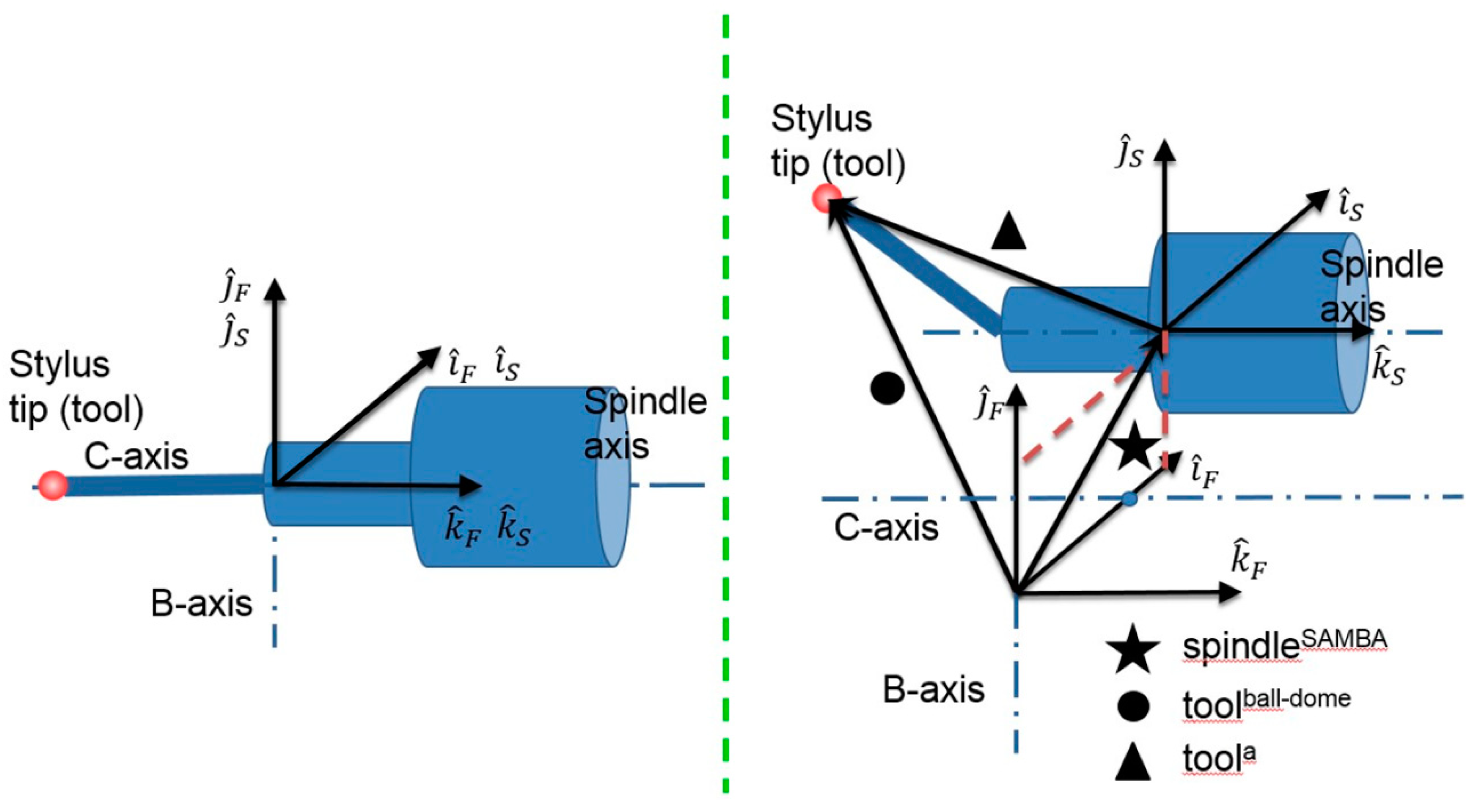
The tool is estimated during the machine calibration using the SAMBA method. However, the stylus tip used to measure the ball dome was different from that used for the SAMBA calibration. In addition, during the dome measurement, the spindle was not rotated so that the tool could not be estimated independently from the spindle position. The spindle location was estimated during the SAMBA calibration conducted a year earlier. A complete machine, tool and ball coordinates estimation are conducted to explain the machine probing readings but only the tool coordinates are further used here. Vector subtraction is used to extract the tool geometry from the two vectors as illustrated in
Figure 4 resulting in the following equation,
where
tooln is the nominal tool geometry used during ball-dome measurement and
is the deviation of the tool geometry calculated by Equation (4) and
where
EXOS and
EYOS are the two spindle lateral offset errors obtained by SAMBA method defined in
Table 2. The kinematics of the machine tool accompanied by the two offset errors contributing in the tool twist estimation are illustrated in
Figure 2.
8. Deviation Results
Table 5 shows the maximum and average deviation calculated for different models. The deviation is between artefact reference probing coordinate from CMM measurements and artefact probing coordinate from the machine tool as a coordinate measuring system. A least square fitting algorithm is applied to best match the two sets of coordinates. For every single ball, the coordinate deviations in x, y and z and the deviation norm, R, are calculated. The maximum and average values of R considering all ball dome balls are calculated.
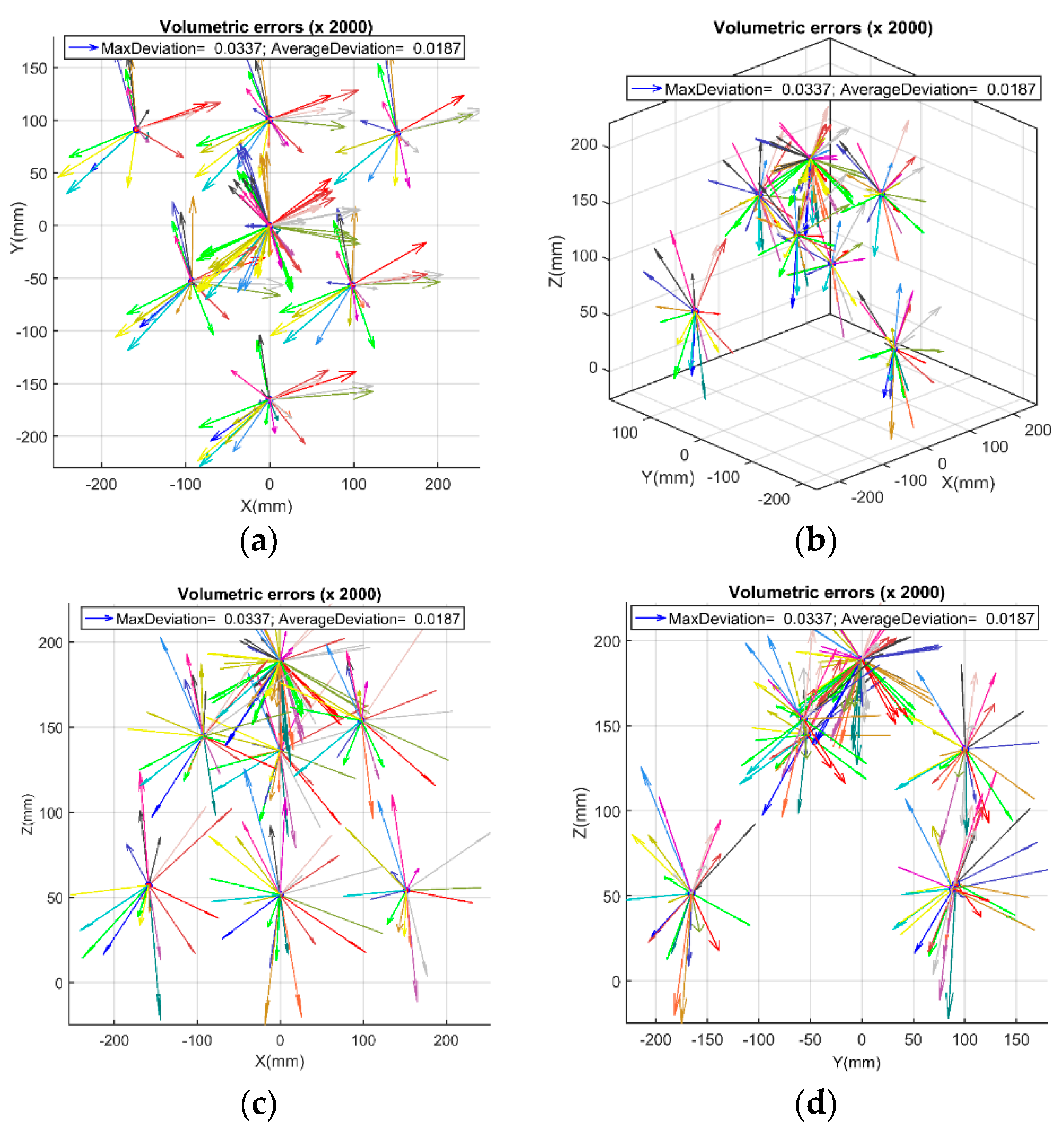
Figure 5 shows the deviation between the calibrated artefact and machine tool measured coordinates while using SAMBA estimated machine and manually estimated stylus tip offsets (item S4), which are used for comparison. The vectors (arrows) are the 3D deviation for every single ball while the reference values are the artefact reference coordinate measured on a CMM and each color represents a specific machine tool axes indexation out of the 24 indexations. Each vector has three Cartesian components; the length of each vector is calculated by Equation (8):
The maximum and average deviations (vector lengths) for the 25 balls at 24 indexations are presented in
Table 4.
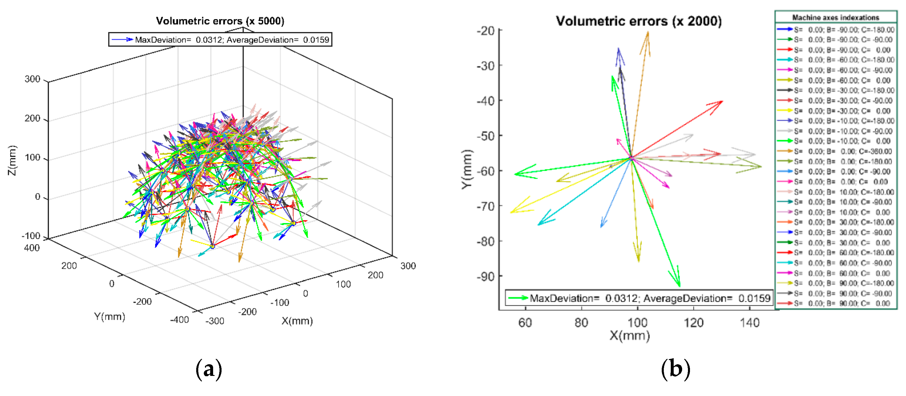
Figure 6 presents the deviation while using the stylus tip offsets calculated based on just one ball on the artefact (item S2). In this case, to lighten the plots, the deviation arrows just for seven selected balls are shown through the artefact.
On the other hand, as it mentioned in
Table 5, while the non-calibrated machine and nominal stylus tip offsets are used, the maximum and average deviations are 176 and 70 µm respectively.
9. Discussion
The SAMBA calibrated machine tool errors parameters are used to compensate the machine for the purpose of on-machine coordinate metrology. The considered errors are eight axis location errors, two spindle lateral offsets, three linear axis positioning scale gain errors and the stylus tip center coordinates (the tool) relative to the spindle frame. The ball dome artefact is used to evaluate the accuracy of the compensated machine. The ball dome includes 25 balls on a quasi-hemispherical envelop fabricated of Invar, which is clamped on kinematic supports to reduce clamping distortion.
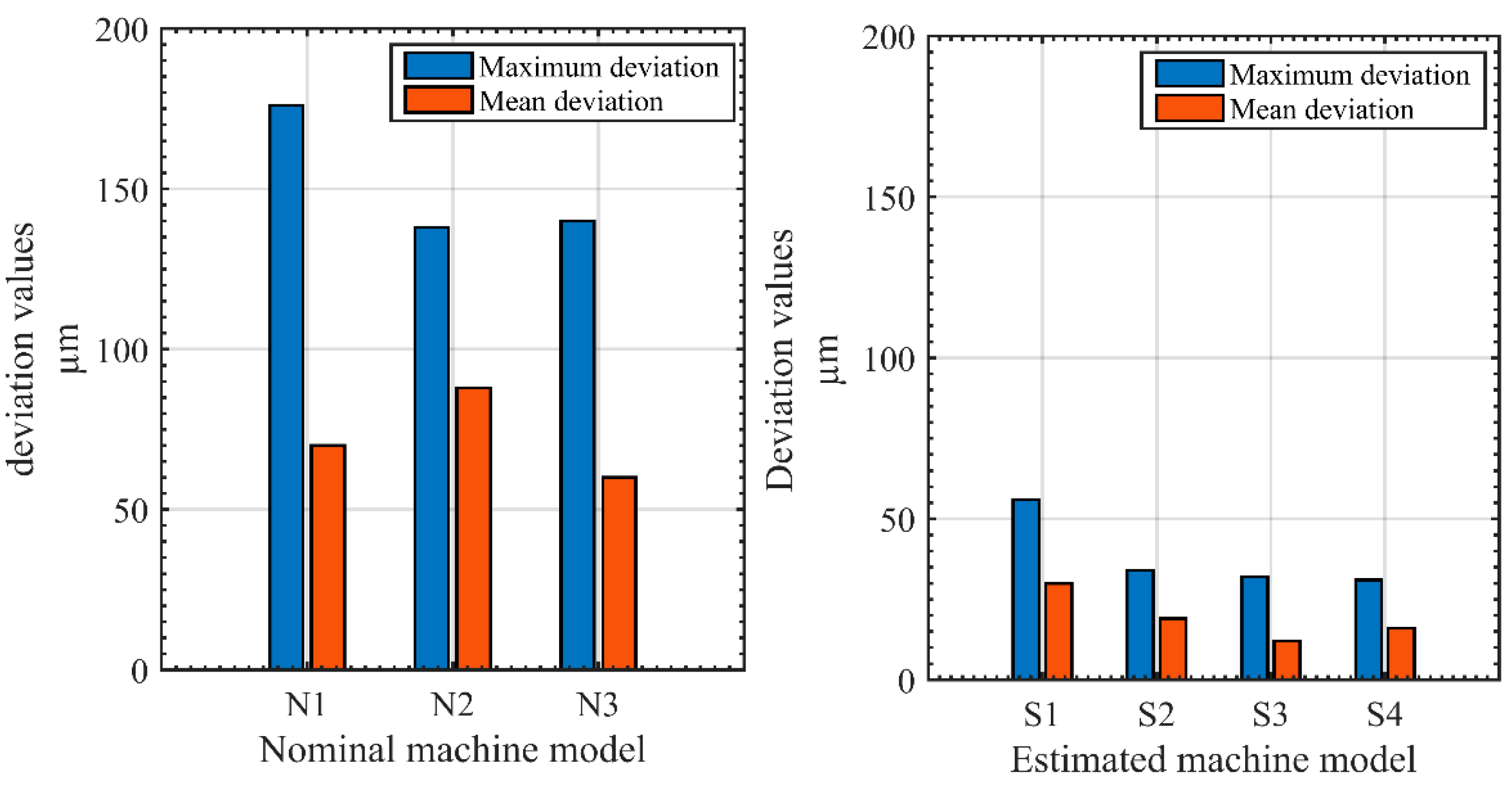
The machine measuring performance when no calibration is applied neither for the machine geometry nor for the stylus tip offsets, displays the maximum and average deviations equal to 176 and 70 µm respectively. Calibrating the machine geometry based on the SAMBA estimated error parameters improves the machine performance and reduces the maximum and average deviation to 56 and 30 µm, respectively, a 60% improvement. Another important error contributor is the stylus tip offsets. There are two options to estimate the stylus tip offsets; the first one is using just one ball on the artefact which leads to 34 and 19 µm as the maximum and average deviations. The results achieved by using the second option, which stands on using all balls, are 32 and 12 µm. The other choice for the stylus tip offsets is achieved by vector calculation between the estimated tool from ball dome data only and estimated spindle from the SAMBA process. For this last case the maximum and average deviation are 31 and 16 µm respectively, the lowest maximum value obtained. The deviation reduction achieved by using calibrated machine and estimated stylus tip offsets is figured in
Figure 7.
10. Conclusions
In this paper, the SAMBA method is used to calibrate the machine tool and to estimate the stylus tip offsets and then the efficiency of the calibration process and estimated models are verified by using the ball dome artefact. Due to the large size of the ball dome, during its measurement by the machine on various rotary axes indexations, all the linear and rotary axes motions are covered and then all the measurement results are transferred to the same reference frame. A single ball measurement would be the preferred option to estimate the stylus tip offsets. This approach provides the lowest average deviation.
Therefore, using the SAMBA calibration method accompanied with an optimized machine and stylus tip offsets has reduced the machine tool maximum and average volumetric errors by 82% and 83% respectively, while all the linear and rotary axes are involved in the coordinate measurement process.
Author Contributions
Conceptualization, J.R.R.M. and H.H.; methodology, H.H.; software, J.R.R.M.; validation, H.H.; formal analysis, H.H., S.E.M. and K.X.; investigation, H.H., S.E.M. and K.X.; resources, H.H. and K.X.; data curation, H.H. and S.E.M.; writing—original draft preparation, H.H.; writing—review and editing, J.R.R.M.; visualization, H.H., S.E.M.; supervision, J.R.R.M.; project administration, J.R.R.M.; funding acquisition, J.R.R.M.
Funding
This research was supported by the Natural Sciences and Engineering Research Council of Canada NSERC Canadian Network for Research and Innovation in Machining Technology–Phase 2: CANRIMT2.
Acknowledgments
The authors would like to thank the valuable support of CNC machine technicians, Guy Gironne and Vincent Mayer during the experimental tests.
Conflicts of Interest
The authors declare no conflict of interest.
References
- Lasemi, A.; Xue, D.Y.; Gu, P.H. Tool path re-planning in free-form surface machining for compensation of process-related errors. Int. J. Prod. Res. 2014, 52, 5913–5931. [Google Scholar] [CrossRef]
- Lee, W.C.; Wang, J.Y.; Wei, C.C. Improving Machining Accuracy by Automatic Compensation Based on the Off-line Measurement. In Proceedings of the 2017 IEEE International Conference on Consumer Electronics–Taiwan (ICCE-TW), Taipei, Taiwan, 12–14 June 2017. [Google Scholar]
- JCGM 200. International Vocabulary of Metrology—Basic and General Concepts and Associated Terms International Vocabulary of Metrology; JCGM: Kasterlee, Belgium, 2012. [Google Scholar]
- ISO. Standard on Machine Tool Accuracy In 230-1; ISO: Geneva, Switzerland, 2012. [Google Scholar]
- Zhang, G.; Veale, R.; Charlton, T.; Borchardt, B.; Hocken, R. Error compensation of co-ordinate measuring machines. CIRP Ann. Manuf. Technol. 1985, 34, 445–448. [Google Scholar] [CrossRef]
- Hocken, J.A.S.R.; Borchardt, B.; Lazar, J.; Reeve, C.; Stein, P. Three Dimensional Metrology. CIRP Ann. Manuf. Technol. 1977, 26, 403–408. [Google Scholar]
- Schwenke, H.; Knapp, W.; Haitjema, H.; Weckenmann, A.; Schmitt, R.; Delbressine, F. Geometric error measurement and compensation of machines—An update. CIRP Ann. Manuf. Technol. 2008, 57, 660–675. [Google Scholar] [CrossRef]
- Ibaraki, S.; Nagai, Y. Formulation of the influence of rotary axis geometric errors on five-axis on-machine optical scanning measurement-application to geometric error calibration by “chase-the-ball” test. Int. J. Adv. Manuf. Technol. 2017, 92, 4263–4273. [Google Scholar] [CrossRef]
- Guiassa, R.; Mayer, J.R.R.; Kops, L. Predictive compliance based model for compensation in multi-pass milling by on-machine probing. CIRP Ann. Manuf. Technol. 2011, 60, 391–394. [Google Scholar] [CrossRef]
- Lasemi, A.; Xue, D.Y.; Gu, P.H. Accurate identification and compensation of geometric errors of 5-axis CNC machine tools using double ball bar. Meas. Sci. Technol. 2016, 27, 055004. [Google Scholar] [CrossRef]
- Bringmann, B.; Kung, A. A measuring artefact for true 3D machine testing and calibration. CIRP Ann. Manuf. Technol. 2005, 54, 471–474. [Google Scholar] [CrossRef]
- Rahman, M.M.; Mayer, R.R.R. Performance of a five-axis machine tool as a coordinate measuring machine (CMM). J. Adv. Mech. Des. Syst. 2016, 10. [Google Scholar] [CrossRef]
- Mayer, J.R.R.; Hashemiboroujeni, H. A ball dome artefact for coordinate metrology performance evaluation of a five axis machine tool. CIRP Ann. Manuf. Technol. 2017, 66, 479–482. [Google Scholar] [CrossRef]
- Givi, M.; Mayer, J.R.R. Optimized volumetric error compensation for five-axis machine tools considering relevance and compensability. CIRP J. Manuf. Sci. Technol. 2016, 12, 44–55. [Google Scholar] [CrossRef]
- Ibaraki, S.; Sawada, M.; Matsubara, A.; Matsushita, T. Machining tests to identify kinematic errors on five-axis machine tools. Precis. Eng. 2010, 34, 387–398. [Google Scholar] [CrossRef]
- Mayer, J.R.R. Five-axis machine tool calibration by probing a scale enriched reconfigurable uncalibrated master balls artefact. CIRP Ann. Manuf. Technol. 2012, 61, 515–518. [Google Scholar] [CrossRef]
- Mchichi, N.A.; Mayer, J.R.R. Axis location errors and error motions calibration for a five-axis machine tool using the SAMBA method. Proc. CIRP 2014, 14, 305–310. [Google Scholar] [CrossRef]
© 2019 by the authors. Licensee MDPI, Basel, Switzerland. This article is an open access article distributed under the terms and conditions of the Creative Commons Attribution (CC BY) license (http://creativecommons.org/licenses/by/4.0/).


