Article

High Seam Surface Quality in Keyhole Laser Welding: Buttonhole Welding

BIAS—Bremer Institut für angewandte Strahltechnik GmbH, Klagenfurter Straße 5, 28359 Bremen, Germany
*
Author to whom correspondence should be addressed.
J. Manuf. Mater. Process. 2018, 2(4), 78; https://doi.org/10.3390/jmmp2040078
Submission received: 18 October 2018 / Revised: 8 November 2018 / Accepted: 12 November 2018 / Published: 14 November 2018
(This article belongs to the Special Issue New Findings and Approaches in Machining Processes)

Abstract

:
Keyhole laser welding experiments with 1.5 mm thick aluminum sheets (EN AW-6082) were carried out with transversal beam oscillation and wire feeding. A circular cavity, which was named buttonhole, formed directly behind the laser spot at certain oscillation frequencies. The welding states “no buttonhole”, “unstable buttonhole”, and “stable buttonhole” were distinguished. The melt pool dynamics were experimentally analyzed and correlated with the resulting roughness and waviness of the seam surfaces. Criteria for stable buttonhole welding were derived. On the basis of the cavity radii relations, it is shown that capillary pressure conditions can explain the movement of the buttonhole with the process.

Graphical Abstract

1. Introduction

The laser has become an indispensable tool for production. Through the development of beam sources and system technology, a wide range of applications is available, covering many fields of manufacturing processes such as primary shaping, forming, joining, cutting, coating, and heat treatment. Laser beam welding is one of the largest areas of application. It not only enables precise and reproducible joining of components, but also, through innovative approaches, the efficient production of seams with high-surface quality, which can be used in parts of the structure that later become visible to the customer [1]. The visible surface quality of a product is significantly linked to the quality perception of the customer, and hence affects their purchase decision [2]. In most cases, weld seams do not fit these optical requirements, for example, the visible parts of automobiles, and must be hidden behind a covering. Weld seams must be “invisible” for the human eye after painting [3]. Sander and Reimann [4] categorized relevant optical criteria for visible seams, whereby a seam is excluded when spatters, pores, notches, or seam holes are present. Threshold parameters are the upper bead roughness, the occurrence of ripples, the homogeneity of the seam course, and the bead rounding [4]. The established process for visible seams in car manufacturing is laser beam brazing, for example for tailgate [5] or car roofs [6]. A main critical process in laser brazing is the wetting of the joint parts by the molten wire material. Effective methods to increase the wettability by improved pre-heating of the base material include the beam oscillation in brazing direction [7] or the usage of a second laser beam [8]. Thermal laser conduction welding typically enables a higher joint strength in comparison to laser brazing, (see e.g., Reference [9]). In both process techniques, namely laser brazing as well as heat conduction laser welding, the amount of absorbed laser energy is almost completely determined by the one-time Fresnel absorption, which limits the energy efficiency of the process, especially in cases of aluminum alloys and solid-state laser sources with a wavelength of approximately 1 µm. Higher energy coupling is possible by applying deep penetration laser welding (keyhole welding). Kawahito et al. [10] showed that the total amount of absorbed laser energy could reach 93% for aluminum or steel for solid-state laser sources. The keyhole, the characteristic vapor capillary in deep penetration laser welding, causes high process dynamics that lead to unwanted visual defects and imperfections like spatters, pores, or notches; see e.g., [11].
Farrel and Ferrario [12] investigated the formation of spatters, notches, and pores in electron beam welding with keyhole formation and found that a high-frequency beam oscillation significantly reduces such defects. Albert and Starcevic [13] found a positive influence on the reduction of seam defects in keyhole welding by one-dimensional laser beam oscillation. The influence of the frequency of a circular beam scanning motion on the formation of the upper bead of aluminum parts was investigated by Dittrich et al. [14], who showed that sampling frequencies higher than 400 Hz causes turbulences in the melt pool, and, accordingly, a wavy solidification pattern of the upper bead. The influence of the energy distribution, which was varied by one- and two-dimensional beam deflection, on the seam quality of laser-welded galvanized steel sheets was investigated by Mahrle and Beyer [15], whereby a smoother and more uniform seam surface was achieved [15]. According to Seefeld and Schultz [16], the essential advantages of beam oscillation are the wide energy distribution due to the oscillation width while simultaneously offering the possibility of high intensity welding. In Reference [17] it was demonstrated that a transversal one-dimensional beam oscillation enabled a significant increase in the gap bridging ability, up to 300% of the sheet thickness [17]. A high-speed camera was used to observe the process behavior and showed the following phenomena at certain oscillation frequencies. A circular cavity was formed in the melt pool directly behind the oscillating keyhole [18]. The cavity showed a stable movement with the process and had an opening diameter similar to the melt pool width. The formation and collapse of this cavity was related to process stability and the occurrence of seam ripples. If this cavity remained stable during welding, this resulted in a smooth seam surface and a straight seam course. The cavity was called the “buttonhole” [18]. Its existence and stability are influenced by the oscillation frequency [18]. A stable process with buttonhole was observed in the case of welding with an oscillation frequency of 250 Hz. The welding with a stable buttonhole cavity was referred to as buttonhole welding [18]. At an oscillation frequency of 200 Hz, the buttonhole became unstable, emerged, and collapsed at intervals of a few millimeters. In the case of lower frequencies, no buttonhole was observed [18]. A comparable phenomenon was observed by Aalderink et al. [19] during bead-on-plate welding of 1.1 mm thick aluminum sheets with a defocused laser beam. A cavity was formed in the seam at high melt pool widths, and the self-sustainability of the cavity was linked to surface tensional forces (Equation (1)) [19]. Figure 1 shows a melt pool with a cavity that has a double-curve nature, according to the illustrations in Reference [19]. A pressure balance at a local position on the cavity wall shows two pressures resulting from the two layers that have different spatial directions ( x z and x y ) (Equation (2)).
p i = σ i r i
p x z = p x y
r x z = r x y
The surface tension pressure can be disregarded since it is similar for both pressures ( σ x z = σ x y ) at each competing point. Consequently, only the radii remain (Equation (3)), whereby the cavity grows when r x y > r x z , and constricts when r x y < r x z .
Aalderink et al. [19] referred to the cavity as a “keyhole”, although the precise nature of the opening is somewhat different from an actual keyhole. They calculated that the vapor pressure characteristic for the keyhole was negligible as the opening was too wide. Eriksson et al. [20] observed the existence of such a cavity in the melt pool during the pulsed laser [21] and continuous wave laser [20] welding of thin steel sheets, referring to the process as “laser donut welding” and describing the cavity as having a catenoid form. They observed that less spatters or pores resulted from this process; however, disadvantages included the reduction of the welding speed as well as the need for “run-on” and “run-off” plates for the cavity to emerge (at process start) and solidify (at process end). They concluded that a catenoid does not emerge if the melt pool width is less than 1.5 times the melt pool height [20]. Both References [19] and [21] described the cavity as a significantly expanded keyhole; this was confirmed by Cho et al. [22]. They also observed that both a keyhole and a buttonhole (cavity) could exist beside each other. In Reference [23], the process development of buttonhole welding was presented. This process featured a transverse oscillating laser beam and filler wire feed. Welds were made on bead-on-plate, in a butt joint, and on an overlap joint [24]. The visual comparison to welding without buttonhole revealed an increase of surface smoothness. The following requirements were concluded in Reference [23] to enable the formation of a stable buttonhole:
  • full penetration through the sheet material
  • the melt pool must be wider than the sheet thickness
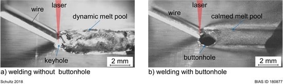
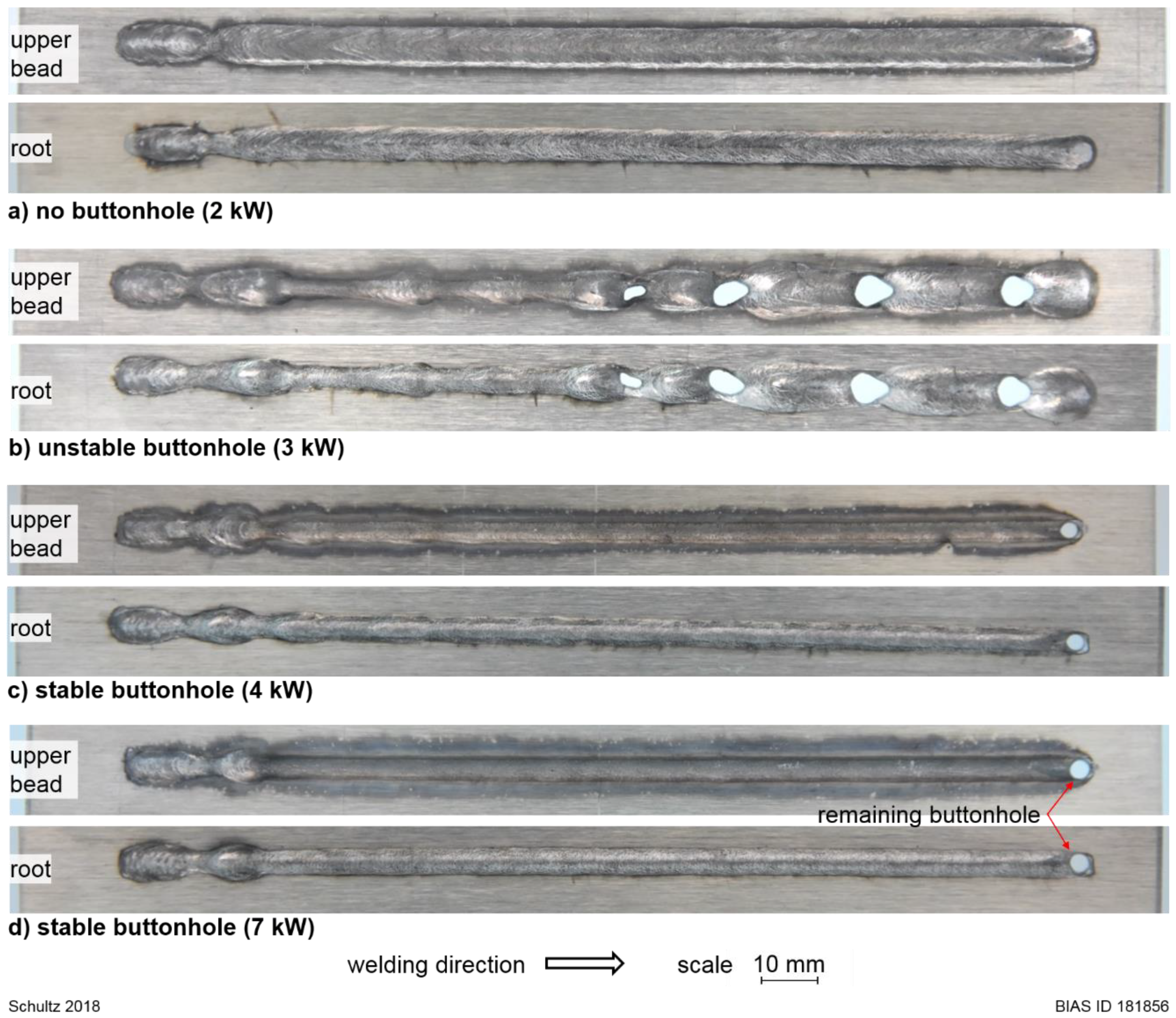
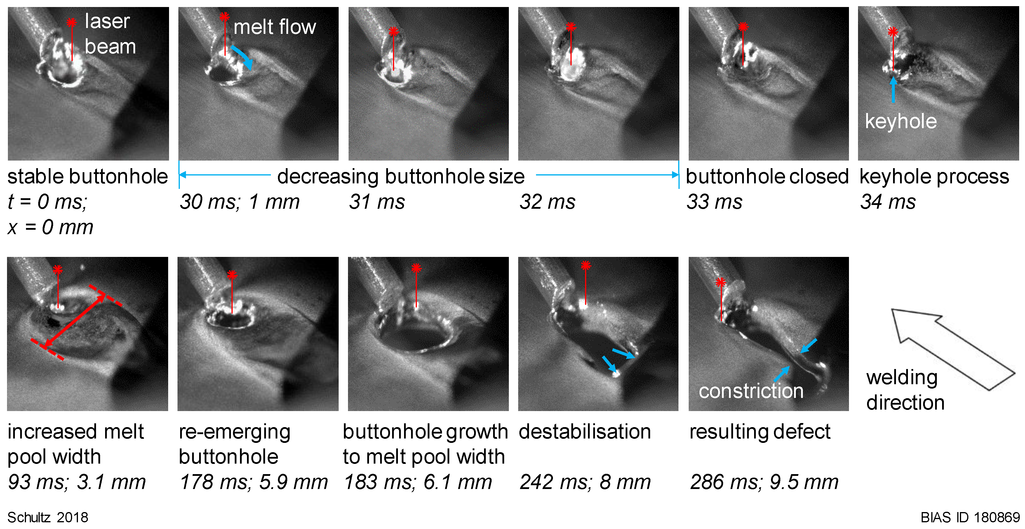
  • oversized melt pool widths lead to a buttonhole destabilization and the risk of pinholes
The process was simulated using computational fluid dynamics (CFDs) in Reference [25], whereby the wire was “chopped” by the transverse oscillating laser, which correlated with the oscillation frequency. In Reference [26], simulations showed that the buttonhole calms the melt pool dynamics behind significantly which can be correlated with surface quality.
So far, it has not been clarified as to why the buttonhole moves with the process instead of remaining in place after its emergence or why it collapses under certain process parameters. In addition, it is not yet fully understood how the buttonhole correlates with the surface quality. This study presents an investigation into the welding of 1.5 mm thick aluminum sheets with a filler wire feed, whereby the buttonhole behavior was analyzed both during its formation as well as in its stable and unstable forms. The silhouette of the buttonhole was recorded with a high-speed camera to investigate the melt pool dynamics and to assign it to a process state (“no buttonhole”, “unstable buttonhole”, and “stable buttonhole”). Finally, the surface quality achieved was determined using roughness and waviness measurements.

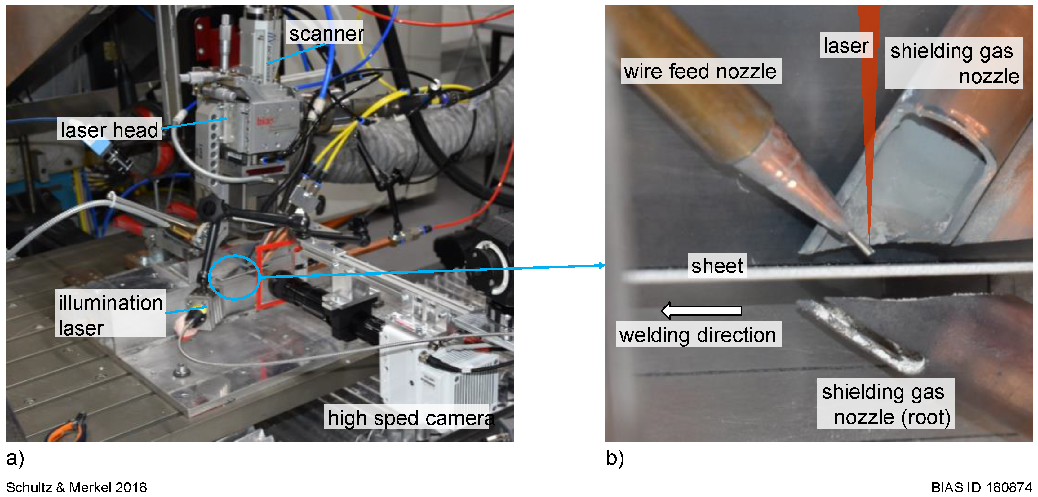
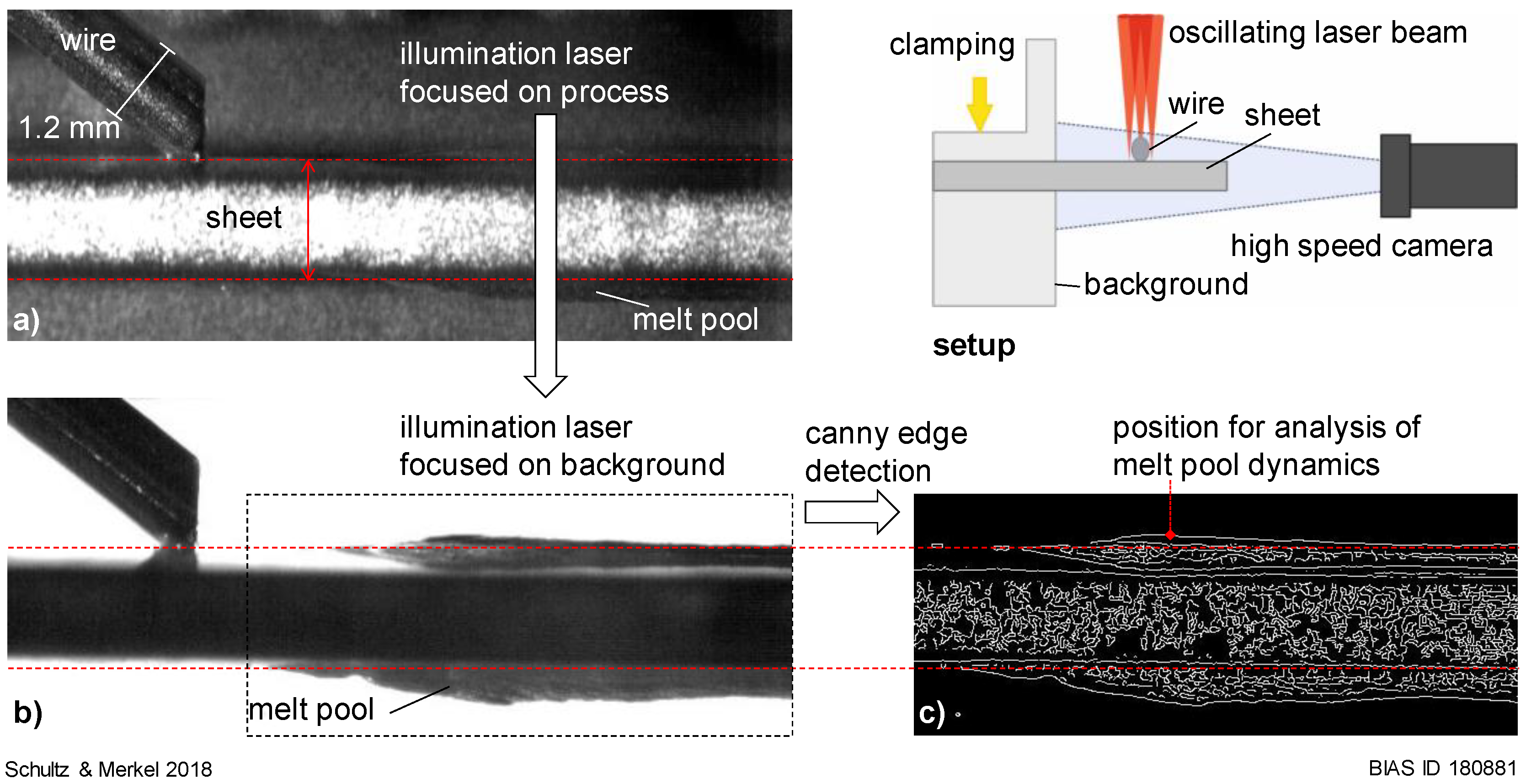
2. Materials and Methods

The laser welding experiments used bead-on-plate welding with a filler wire feed. Experiments were conducted with a Trumpf TruDisk12002 laser source; the setup overview is presented in Figure 2a. The welding head used was a Trumpf BEO D70. An ILV 1D DC Scanner was added to enable a beam oscillation transverse to the welding direction. Collimation and focal length were both 200 mm, providing a nominal spot diameter of 200 µm. A filler wire was fed into the process in a leading configuration; see Figure 2b. The process parameters are listed in Table 1. The upper melt pool was protected against oxidation with argon. Helium was delivered to the lower melt pool using a nozzle that moved with the process. A high-speed camera, Vision Research Phantom VEO 410, was used to observe the emergence and stability of the buttonhole from above during the process. In addition, the longitudinal silhouette of the melt pool was captured via a high-speed camera, see Figure 3, which enabled the melt pool dynamics to be recorded. The recording speed was set to 10,000 fps. The process was illuminated by a Cavitar Cavilux laser, and its focus was adjusted to facilitate a good edge contrast between the background and the melt pool; see Figure 3a (focus on process) and Figure 3b (focus on background). Edge detection was carried out with a Matlab routine using the Canny algorithm [27]; see result in Figure 3c. A Fourier analysis of the melt pool dynamics was conducted at a measuring point 3 mm behind the melting wire tip. These investigations were carried out for the different process parameters, and the results were correlated with the buttonhole behavior. In addition to the observation of the buttonhole and melt pool dynamics, the influence of the buttonhole on the surface quality was investigated by measuring the mean roughness and waviness, for which a 3D laser scanning confocal microscope (Keyence VK-9700) was used. The measurement path was set along seam direction and had a length of 50 mm. For each investigated parameter, set one measurement was conducted.

3. Results

Figure 4 demonstrates the process of laser welding both without and with a buttonhole. The buttonhole separates the front of the melt pool from the rear melt pool, and thus the material flow has to proceed around the buttonhole through melt channels to the rear melt pool. Nevertheless, the buttonhole obviously calms the melt pool dynamics behind it, resulting in a smoother weld seam.
Figure 5 shows the influence of laser power on the existence and stability of the buttonhole during buttonhole welding. There is a transition area from 2 kW to 4 kW where the buttonhole is either not present, unstable, or stable. A process window was presented by the authors in Reference [23]. Hereby, all seams showed a constriction of the seam at the beginning, which was the result of the first emergence of the buttonhole. Subsequently, a material accumulation could be detected, which was observed in the video recordings as a droplet on the wire tip that flowed into the melt pool. At 2 kW (Figure 5a), the buttonhole collapsed after the wire material had been added, and at high laser powers it remained. A stable buttonhole process first appeared at 4 kW (Figure 5c) with a filler wire feed. A higher laser power of 7 kW (Figure 5d) did not have any considerable influence on the seam shape or the emergence of the buttonhole. The buttonhole remained at the end of the process, what is typical for buttonhole welding, as shown in observations here. Ericsson et al. [20] suggested to use run-in and run-out plates to prevent defects from welding with such a cavity. Otherwise the process would not be practical. The unstable form of the buttonhole emerged at 3 kW, whereby the width of the seam was no longer constant along its length and several pinholes remained.
Figure 6 gives the vertical melt pool oscillation amplitude of the upper bead as a function of the frequency for six different laser powers. When no buttonhole existed (2 kW), the melt pool dynamics lay primarily within a range of 450 Hz to 550 Hz with a peak at 500 Hz and an amplitude of 50 µm. In the unstable form at 3 kW, the alternating emergence and collapse of the buttonhole was observed. This led to greater melt pool amplitudes within a frequency range of 1 Hz to approximately 200 Hz. For the stable buttonhole process (4 kW to 7 kW), the predominant amplitudes were observed to be below 10 Hz, at 86 Hz, at 250 Hz, and at 500 Hz. Considering the oscillation frequency of the scanning unit (250 Hz), a direct relationship can be determined for higher frequencies in the melt pool dynamics (86 Hz is approx. 1/3 of 250 Hz). In particular, the amplitude at a frequency of 86 Hz increases with increasing laser power.
Figure 7 provides an isometric view of the welding process as well as the buttonhole emergence along a weld path of about 10 mm. A keyhole is visible prior to the emergence of the buttonhole. The second frame shows a small buttonhole in its early form as well as its growth from the keyhole. By the time the wire reaches the melt pool, the buttonhole has stabilized, and while the additional material from the filler wire significantly decreases the buttonhole diameter, it does not destabilize it.
Figure 8 shows the buttonhole for a half beam oscillation period, demonstrating that the form of the buttonhole is affected by the position of the transverse oscillating laser beam. When the laser beam is at the outer left position (t = 0 ms), in relation to the welding direction, the left side of the melt pool front is marginally ahead of the right side. This results in an elliptically shaped buttonhole that is diametrically aligned to the laser beam, thus the primary melt pool flow runs from the front to the rear melt pool along the right side of the buttonhole according to the welding direction. When the laser oscillates to the right side, it melts the wire tip as it passes (the wire is “chopped” by the laser beam). After the laser reaches its outermost oscillation position on the right side (t = 2.5 ms), the right side of the melt pool front moves ahead of the left side. The elliptically formed buttonhole is now aligned to the right side, i.e., the current position of the laser, and the primary melt pool shifts to the left side of the buttonhole.
The unstable form of buttonhole welding is presented in Figure 9 (beginning of collapse after t = 30 ms and destabilization/constriction after t = 242 ms/286 ms). The second picture shows the beginning of its collapse, whereby for unknown reasons the buttonhole is displaced to one side and closes completely after a few milliseconds. What remains is a conventional keyhole. The melt pool width increases. The buttonhole reforms after a short period of time and grows as wide as the edges of the melt pool permit. A second destabilization follows at t = 183 ms, whereby the greatly enlarged buttonhole starts to elongate in a backwards direction, which finally results in its constriction, leaving a hole in the seam.
The mean roughness and waviness in dependence on the laser power and oscillation frequency are given in Figure 10. Roughness and waviness values for the stable buttonhole are consistently lower than those for the other states. An increase in laser power within the region of a stable buttonhole does not have any considerable influence on the surface smoothness.

4. Discussion

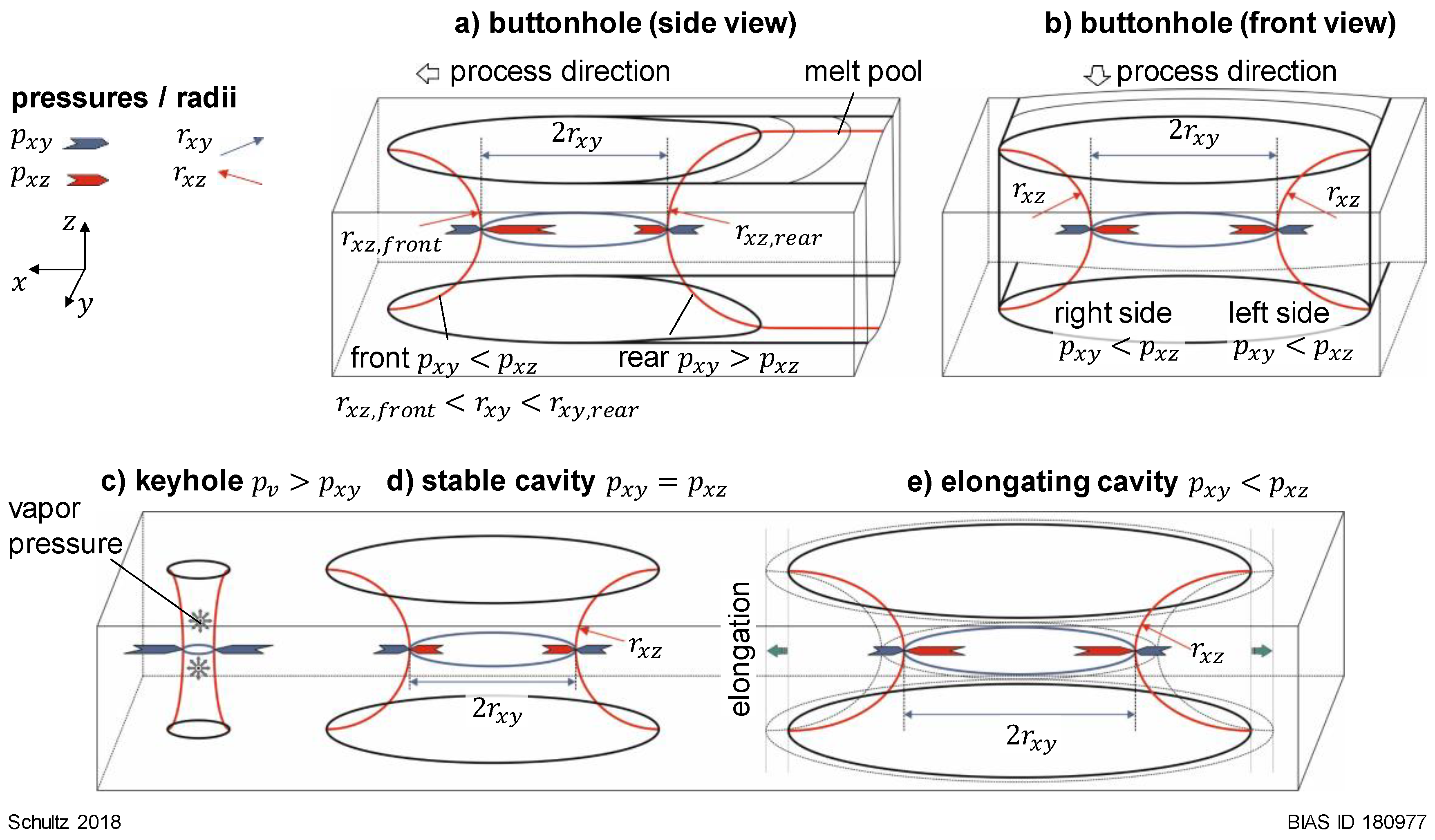
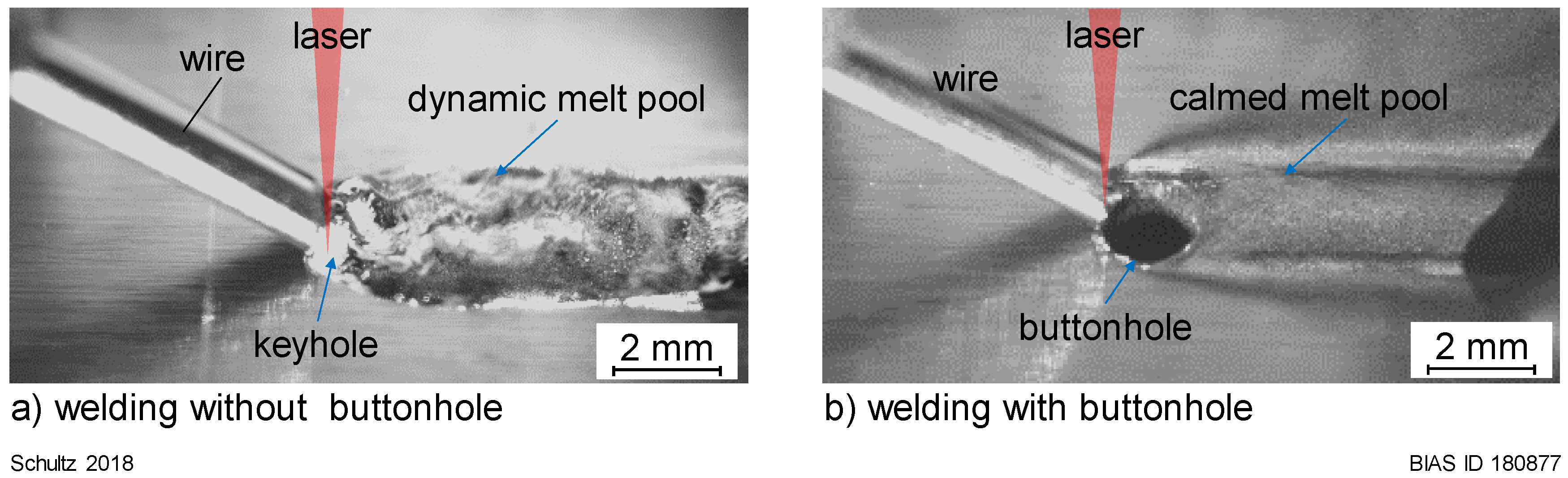
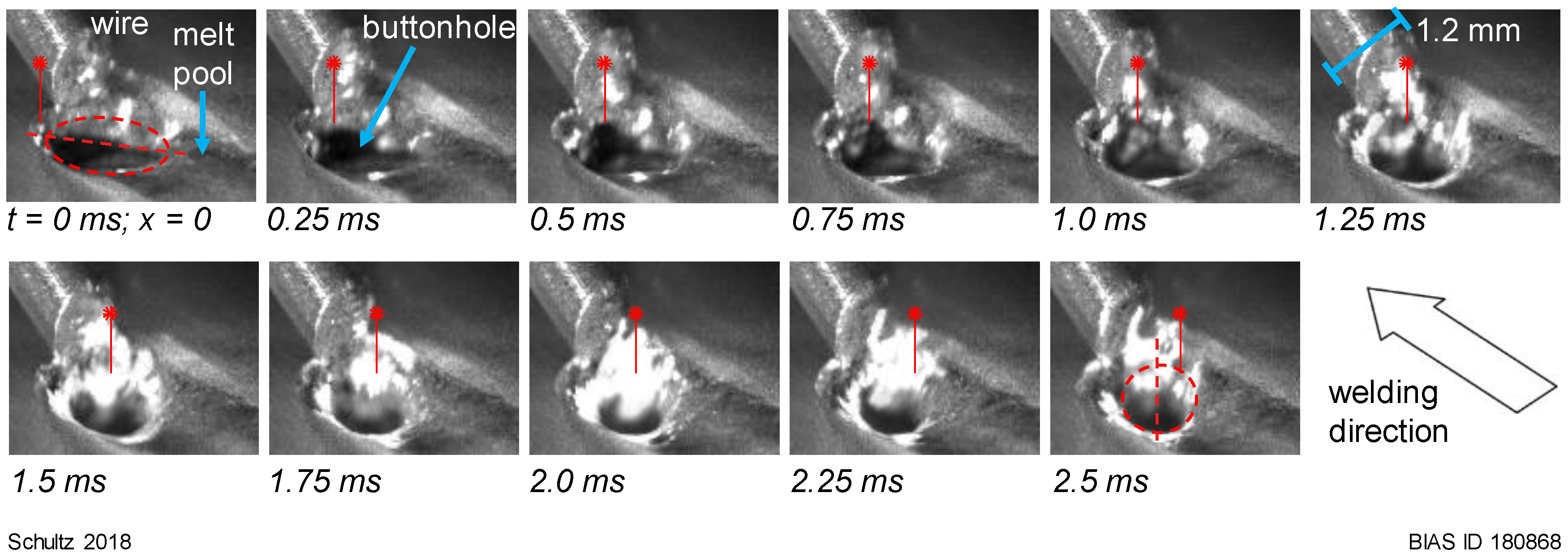
4.1. Buttonhole Movements with Process

A simplified model presented in Reference [19] explains the self-sustainability of a cavity in a melt pool by capillary pressure balance. This can be transferred to buttonhole welding, but it has not been clarified as to why the buttonhole moves with the process instead of remaining in place after its emergence or why it collapses under certain process parameters.
According to the rules of self-sustainability, its movement must be based on the capillary pressure. Four buttonhole regions shall be considered for explanation: front-wall, rear-wall, and two side-walls. Based on the relations according to Reference [19] and the results of this study, it is assumed that the front buttonhole wall moves with welding direction when p x z > p x y is fulfilled. According to Equation (1), the radius r x z , f r o n t of the buttonhole front wall must be smaller than r x y , see Figure 11a (buttonhole side view). In the case of the opposite relation between the pressures ( p x z < p x y ), the buttonhole front wall would move against the process direction. The cavity would detach from the welding front and collapse or remain as hole in the seam depending on the rear wall behavior.
The rear buttonhole wall would be stable and move with the process, when p x z < p x y and r x z , r e a r > r x y is fulfilled. This is well known from the typical keyhole (Figure 11c) in conventional deep penetration laser welding, which, in contrast to the buttonhole, must be held open by the high vapor pressure due to the very small keyhole radius r x z , k e y h o l e . A too high ration of r x z , r e a r and r x y would result in the collapse of the buttonhole. In case of the opposite capillary radius relation ( r x z , r e a r < r x y ), the buttonhole would elongate, see Figure 11e (elongating cavity). This behavior was observed in the experiments, see Figure 9 at t = 183 ms and the following frames.
In sum, the radii condition r x z , f r o n t < r x y < r x z , r e a r must be fulfilled for a buttonhole moving with the process in the welding direction. It has to be noted that fluid dynamic effects of the melt pool flows have not been considered in this derivation of the specific conditions in buttonhole welding.

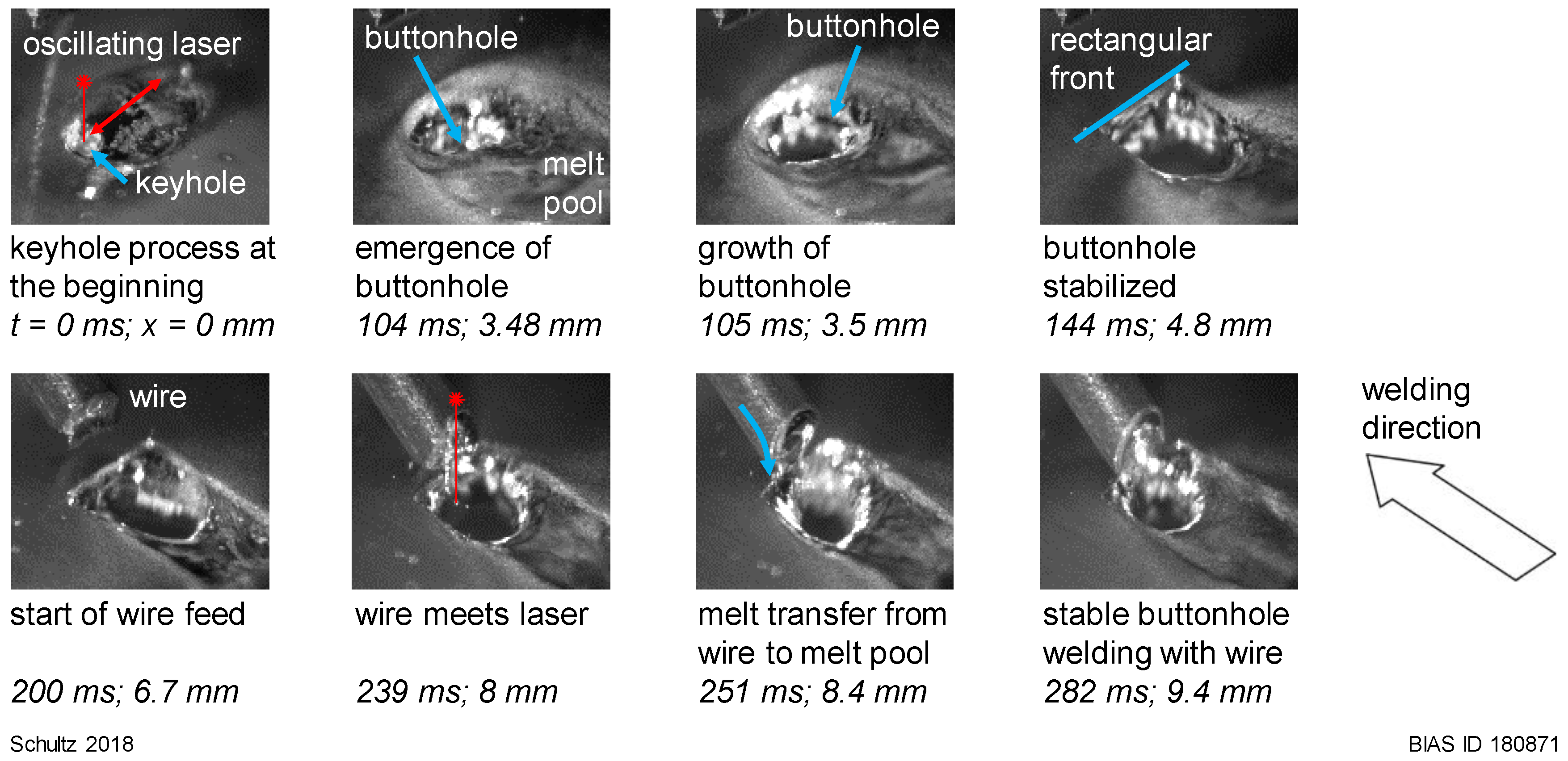
4.2. Transition from Keyhole Welding with Oscillating Beam to Buttonhole Welding

Figure 5 shows that the laser power has an influence on the emergence of the buttonhole. Further influences on the existence of a buttonhole were presented in Reference [18] for the oscillation frequency and in Reference [22] for the oscillation width. All data show a transition area from “no buttonhole” to “stable buttonhole”. Within the transition area, the buttonhole emerges and collapses repetitively; see Figure 5. Two mechanisms for the collapse of the buttonhole were observed. One is the collapse of the buttonhole due to an oversized melt pool/buttonhole, the prerequisite for which is a critical radii condition at the rear buttonhole wall, as previously described. The other mechanism is shown in Figure 9 after 30 ms. For reasons unknown, the buttonhole is displaced to one side and collapses. Similar observations were found for buttonhole welding in Reference [18].

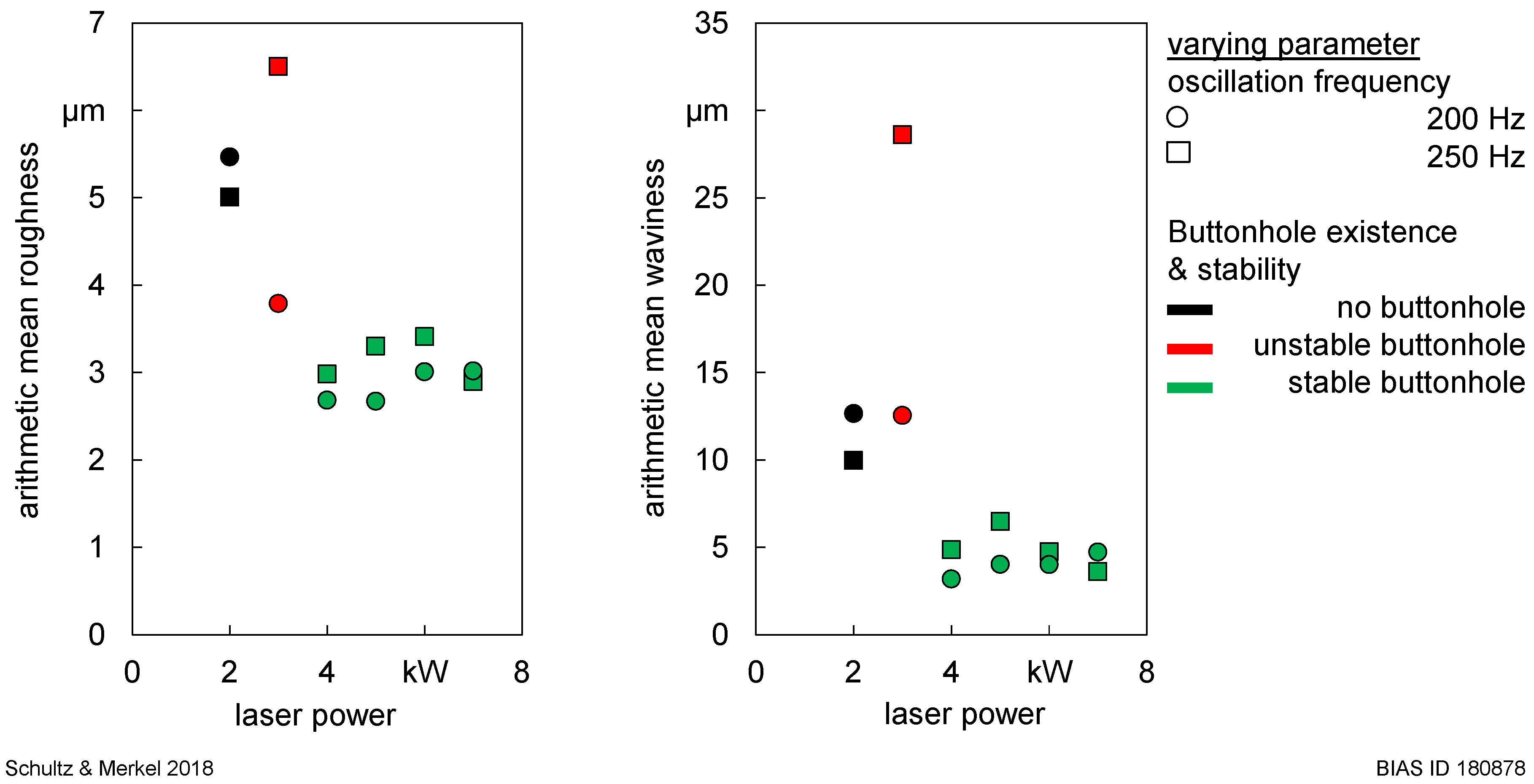
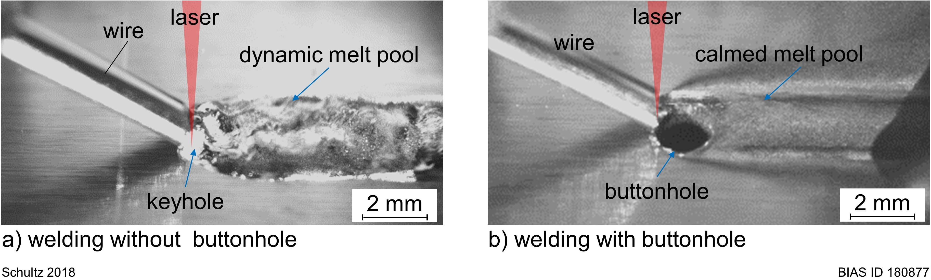
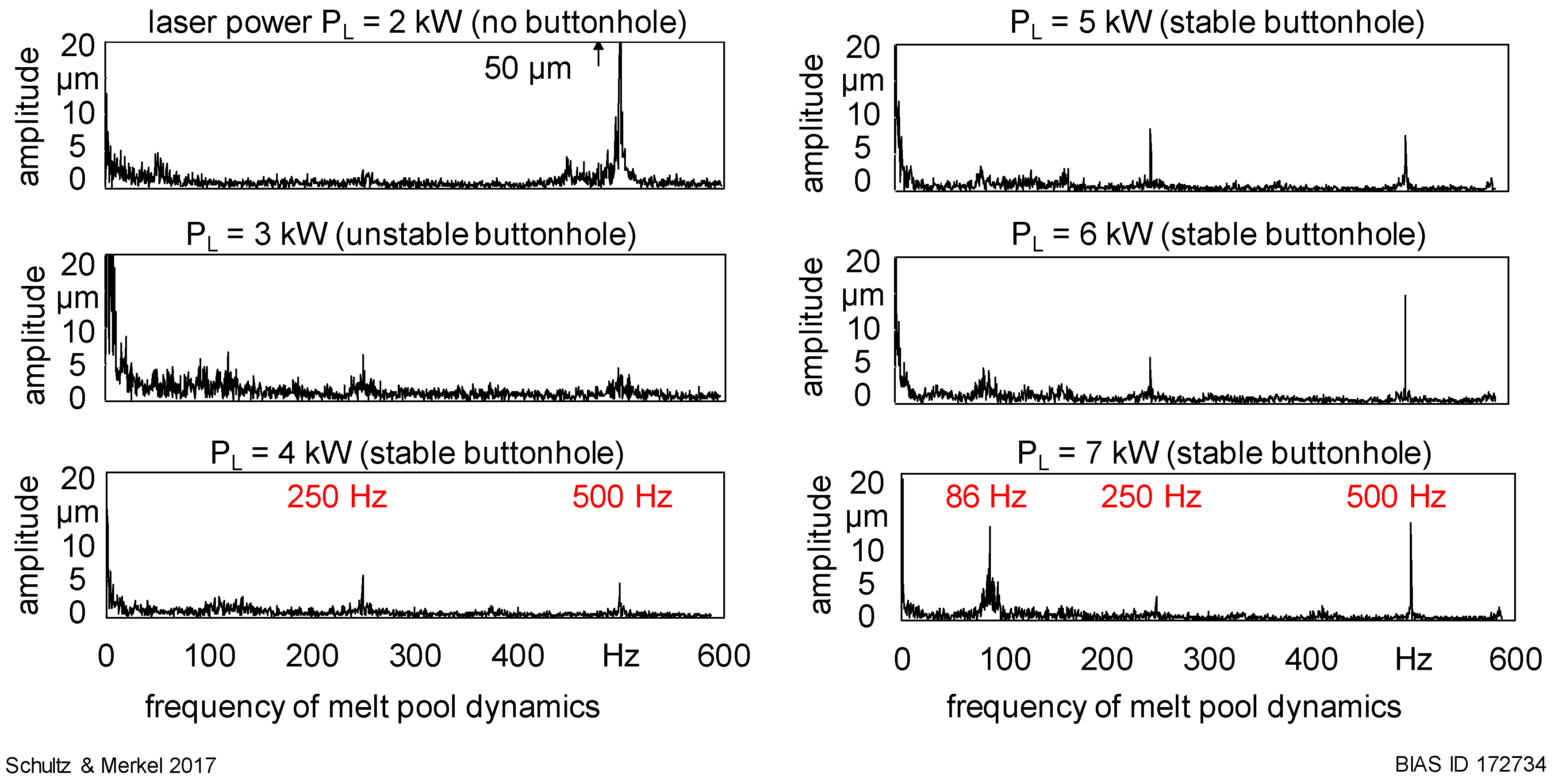
4.3. Influence of Melt Pool Dynamics on the Surface Quality

The analysis of the melt pool dynamics of the upper bead has been shown in Figure 6. Notable are the amplitude peaks at very low frequencies beneath 20 Hz, as well as at frequencies that relate to the beam oscillation frequency, namely 86 Hz, 250 Hz, and 500 Hz, which partially represent multiples of the beam oscillation frequency. Each welding state can be related to its frequency spectra. When welding with a stable buttonhole, the detected peaks that are in relation to the beam oscillation are all beneath 15 µm. Without a buttonhole, one single outstanding peak was detected at 500 Hz with an amplitude of 50 µm; see Figure 6 at PL = 2 kW. These higher amplitudes at high frequencies indicate great accelerations and oscillation speeds of the melt pool, which correlates with a high degree of pool dynamics compared to stable buttonhole welding. This is confirmed by the camera observations (Figure 4) and CFD simulations in Reference [26], which showed that buttonhole welding significantly reduces the melt pool dynamics. Outstanding peaks in the frequency spectra of an unstable buttonhole are much lower than for other conditions; see Figure 5 at PL = 3 kW. Nevertheless, there was an overall increase in the amplitude along the frequency spectra results. One explanation for this could be the permanently changing melt pool behavior; see Figure 9. A reduction of the mean arithmetic roughness and waviness when welding with a buttonhole is shown in Figure 10 and can be correlated to the reduction in the melt pool dynamics shown by the frequency spectra.

5. Conclusions

The buttonhole existence significantly reduces the melt pool dynamics in keyhole welding with wire feeding and beam oscillation, which leads to a significant reduction in the surface roughness and waviness in comparison with processes without buttonhole formation. In addition to the criteria for the buttonhole emergence, presented in Reference [23], the following conclusions can be drawn on the basis of this study regarding the movement of the buttonhole with the process:
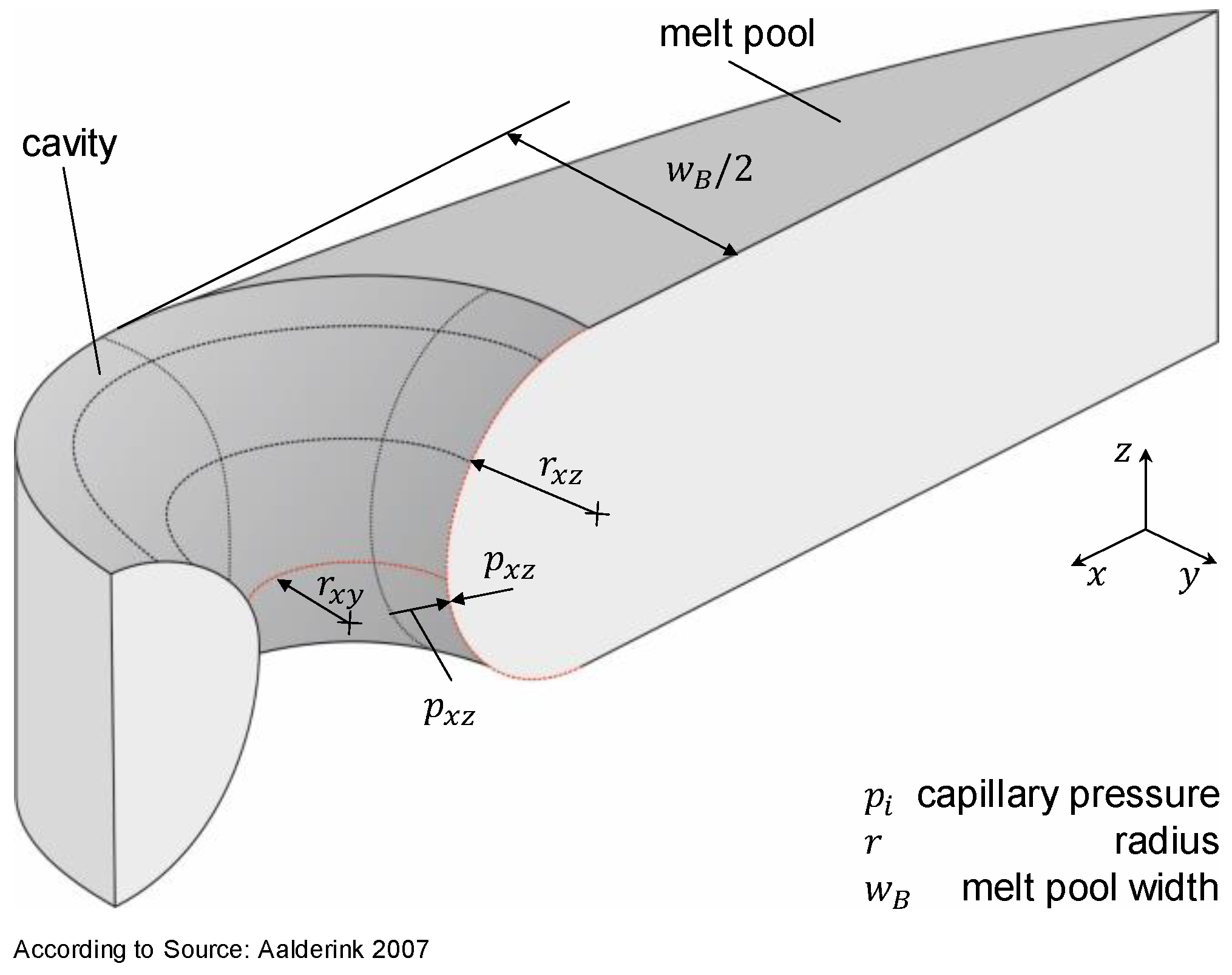
  • the movement of the buttonhole with the process is determined by the radii ratio r x z , f r o n t < r x y < r x z , r e a r
  • a too large rear wall radius r x z , r e a r would result in the constriction of the buttonhole
  • a too small rear wall radius r x z , r e a r would result in buttonhole elongation and remaining pinholes in the seam.

Author Contributions

Conceptualization, V.S.; methodology, V.S.; data analysis, V.S.; investigation, V.S.; writing—original draft preparation, V.S.; content discussions, review and editing, P.W.; supervision, P.W.; project administration, P.W.; funding acquisition, V.S. and P.W.

Funding

This work was accomplished within the Center of Competence for Welding of Aluminum Alloys CentrAl. Funding by the Deutsche Forschungsgemeinschaft (DFG, German Research Foundation, project number 290705638) is gratefully acknowledged.

Acknowledgments

The authors would like to thank Alexander Merkel for performing experiments and Matlab-based data processing and Won-Ik Cho for his support.

Conflicts of Interest

The authors declare no conflict of interest.

References

  1. Vollertsen, F.; Woizeschke, P.; Schultz, V.; Mittelstädt, C. Developments for laser joining with high-quality seam surfaces. Lightweight Des. Worldw. 2017, 5, 6–13. [Google Scholar] [CrossRef]
  2. Haenraets, U.; Ingwald, J.; Haselhoff, V. Gütezeichen und ihre Wirkungsbeziehungen—Ein Literaturüberblick. Int. J. Mark. 2012, 51, 147–163. (In German) [Google Scholar] [CrossRef]
  3. Braess, H.-H.; Seiffert, U. ATZ-MTZ-Fachbuch; Springer Vieweg Verlag: Wiesbaden, Germany, 2014; p. 548. (In German) [Google Scholar]
  4. Sander, J.; Reimann, W. Development of a benchmark criteria for the evaluation of optical surface appearance qualities of brazing and welding connections. In Proceedings of the 16th European Automotive Laser Applications (EALA), Bad Nauheim, Germany, 28–29 January 2015. [Google Scholar]
  5. Tang, Z.; Seefeld, T.; Vollertsen, F. Laser Brazing of Aluminum with a new filler wire AlZn13Si10Cu4. Phys. Procedia 2013, 41, 128–136. [Google Scholar] [CrossRef]
  6. Engelbrecht, L. Umstieg von YAG auf Diode: Mehr Prozessstabilität, weniger Kosten beim Laserlöten der Dachnullfuge mit angepassten Strahleigenschaften. In Proceedings of the 8th European Automotive Laser Applications (EALA), Bad Neuheim, Germany, 6–7 February 2009. (In German). [Google Scholar]
  7. Heitmanek, M.; Dobler, M.; Graudenz, M.; Perret, W.; Göbel, G.; Schmidt, M.; Beyer, E. Laser brazing with beam scanning: Experimental and simulative analysis. Phys. Procedia 2014, 56, 689–698. [Google Scholar] [CrossRef]
  8. Mittelstädt, C.; Seefeld, T.; Reitemeyer, D.; Vollertsen, F. Two-beam laser brazing thin sheet steel for automotive industry using Cu-base filler material. Phys. Procedia 2014, 56, 699–708. [Google Scholar] [CrossRef]
  9. Schwartz, M. Brazing, 2. Auflage; ASM International: Geauga County, OH, USA, 2003. [Google Scholar]
  10. Kawahito, Y.; Matsumoto, N.; Abe, Y.; Katayama, S. Relationship of laser absorption to keyhole thin um in high power fiber laser welding of stainless steel and thin um alloy. J. Mater. Process. Technol. 2011, 211, 1563–1568. [Google Scholar] [CrossRef]
  11. Volpp, J. Keyhole stability during laser welding—Part II. Prod. Eng. Res. Dev. 2017, 11, 9–18. [Google Scholar] [CrossRef]
  12. Farrel, W.J.; Ferrario, J.D. A computer-controlled, wide bandwidth deflection system for electron beam welding and heat treating. Weld. J. 1987, 10, 41–49. [Google Scholar]
  13. Albert, F.; Starcevic, D. Möglichkeiten zur Beeinflussung der Nahtrauheit beim Laserstrahlschweißen von Türen und Klappen aus Aluminium. In Proceedings of the 10th Laser-Anwenderforum (LAF’16), Bremen, Germany, 23–24 November 2016. (In German). [Google Scholar]
  14. Dittrich, D.; Schedewy, R.; Brenner, B.; Standfuß, J. Laser-multi-pass-narrow-gap-welding of hot crack sensitive thick Aluminium plates. Phys. Procedia 2013, 41, 225–233. [Google Scholar] [CrossRef]
  15. Mahrle, A.; Beyer, E. Control of the energy deposition during laser beam welding by oscillation techniques. In Lasers in Manufacturing; Vollertsen, F., Emmelmann, C., Schmidt, M., Otto, A., Eds.; AT-Fachverl: Stuttgart, Germany, 2007; pp. 97–103. [Google Scholar]
  16. Seefeld, T.; Schultz, V. New developments in filler wire assisted laser joining of Aluminium. In Proceedings of the LAMP2013—6th International Congress on Laser Advanced Materials Processing, Niigata, Japan, 23–26 July 2013. [Google Scholar]
  17. Schultz, V.; Seefeld, T.; Vollertsen, F. Gap Bridging Ability in Laser Beam Welding of Thin Aluminum Sheets. Phys. Procedia 2014, 56, 545–553. [Google Scholar] [CrossRef]
  18. Vollertsen, F. Loopless Production: Definition and Examples from Joining. In Proceedings of the 69th IIW Annual Assembly and International Conference, Melbourne Convention Exhibition Centre, Melbourne, Australia, 10–15 July 2016. [Google Scholar]
  19. Aalderink, B.J.; de Lange, D.F.; Aarts, R.G.K.M.; Meijer, J. Keyhole shapes during laser welding of thin metal sheets. J. Phys. D Appl. Phys. 2007, 40, 5388–5393. [Google Scholar] [CrossRef]
  20. Ericsson, I.; Powell, J.; Kaplan, A. Surface tension generated defects in full penetration laser keyhole welding. J. Laser Appl. 2014, 26, 012006. [Google Scholar] [CrossRef]
  21. Haglund, P.; Eriksson, I.; Powell, P.; Kaplan, A. Surface tension stabilized laser welding (donut laser welding)—A new laser welding Technique. J. Laser Appl. 2013, 25, 031501. [Google Scholar] [CrossRef]
  22. Cho, W.-I.; Schultz, V.; Vollertsen, F. Simulation of the buttonhole formation during laser welding with wire feeding and beam oscillation. In Proceedings of the Lasers in Manufacturing (LIM17), Munich, Germany, 26–29 June 2017. [Google Scholar]
  23. Schultz, V.; Cho, W.-I.; Woizeschke, P.; Vollertsen, F. Laser deep penetration weld seams with high surface quality. In Proceedings of the Lasers in Manufacturing (LIM17), Munich, Germany, 26–29 June 2017. [Google Scholar]
  24. Schultz, V.; Cho, W.; Woizeschke, P. Buttonhole welding—Laser deep penetration welds with smooth seam surface. In Proceedings of the IIW Intermediate Meeting 2018 Com. IV, Lendava, Slovenia, 12–14 March 2018. [Google Scholar]
  25. Cho, W.-I.; Schultz, V.; Woizeschke, P. Numerical study of the effect of the oscillation frequency in buttonhole welding. J. Mater. Process. Technol. 2018, 261, 202–212. [Google Scholar] [CrossRef]
  26. Cho, W.-I.; Woizeschke, P.; Schultz, P. Simulation of molten pool dynamics and stability analysis in laser buttonhole welding. Procedia CIRP 2018, 74, 687–690. [Google Scholar] [CrossRef]
  27. Canny, J. A Computational Approach to Edge Detection. IEEE Trans. Pattern Anal. Mach. Intell. 1987, 6, 679–698. [Google Scholar]
Figure 1. Catenoid in melt pool.
Jmmp 02 00078 g001
Figure 2. Experimental setup: (a) overview and (b) close-up view of the process.
Jmmp 02 00078 g002
Figure 3. Recording and detection of melt pool silhouette: (a) close-up camera view of the silhouette; (b) illumination laser focused on the clamping background; (c) edge detection with Canny algorithm.
Jmmp 02 00078 g003
Figure 4. Welding without and with a buttonhole: (a) laser power of 2 kW and (b) laser power of 4 kW.
Jmmp 02 00078 g004
Figure 5. Influence of the laser power on the existence and stability of the buttonhole (oscillation width 1.1 mm; oscillation frequency 250 Hz; welding speed 2 m/min; wire feed speed 1.4 mm).
Jmmp 02 00078 g005
Figure 6. Melt pool dynamics at the analysis position for different laser powers (oscillation width 1.1 mm; oscillation frequency 250 Hz; welding speed 2 m/min; wire feed speed 1.4 mm).
Jmmp 02 00078 g006
Figure 7. First formation of the buttonhole (laser power 4 kW, oscillation width 1.1 mm; oscillation frequency 250 Hz; welding speed 2 m/min; wire feed speed 1.4 mm).
Jmmp 02 00078 g007
Figure 8. Stable buttonhole welding (laser power 4 kW, oscillation width 1.1 mm; oscillation frequency 250 Hz; welding speed 2 m/min; wire feed speed 1.4 mm).
Jmmp 02 00078 g008
Figure 9. Unstable buttonhole during welding (laser power 3 kW, oscillation width 1.1 mm; oscillation frequency 250 Hz; welding speed 2 m/min; wire feed speed 1.4 mm).
Jmmp 02 00078 g009
Figure 10. Mean roughness and waviness in dependence of the laser power and oscillation frequency (each mark is the result of a 50 mm long measurement line on the surface of one seam).
Jmmp 02 00078 g010
Figure 11. Pressures and radii condition in the cases of a typical keyhole, a stable cavity, an elongating cavity, and the buttonhole.
Jmmp 02 00078 g011
Table 1. Process parameters.
ParameterSymbolUnitValue/Range
Laser power P L k W 2 to 7
Welding speed v c m / m i n 2
Wire feed speed v D m / m i n 1.4
Wire diameter d D m m 1.2
Oscillation width b O s m m 1.1
Oscillation frequency f O s H z 200, 250

