Article

Experimental Investigation on the Geometrical Accuracy of the CNC Multi-Pass Sheet Metal Spinning Process

Production Engineering Department, Faculty of Engineering, Alexandria University, Alexandria 21544, Egypt
*
Author to whom correspondence should be addressed.
J. Manuf. Mater. Process. 2018, 2(3), 59; https://doi.org/10.3390/jmmp2030059
Submission received: 29 July 2018 / Revised: 23 August 2018 / Accepted: 30 August 2018 / Published: 3 September 2018
(This article belongs to the Special Issue Analysis and Modeling of Sheet Metal Forming Processes)

Abstract

:
The geometrical accuracy of multi-pass sheet metal spinning products is crucial in many applications. Aerospace, petroleum, and chemical industries motivated the development of modern spun components of complicated shapes with special functionality, but a substantial research lag exists behind this progress. Due to the localized plastic deformation involved, careful control of dimensions and form is required in spinning procedures. In this study, two sets of experiments were implemented for cup manufacturing using a retrofitted computer numerically controlled (CNC) spinning machine to identify the critical factors affecting product geometry and reveal their influence on the shape accuracy of the spun cups. The first set is a screening experiment to determine the most significant parameters and the second provides the optimum processing conditions affecting cup quality. The feed ratio, number of spin-forming passes, spinning ratio, and lubrication were found to have the most important effect on the geometry of the spun cups. Optimum quality with a higher processing speed (productivity) was achieved under a lubricated condition using a larger number of spin-forming passes at a high feed ratio, diminishing the commonly adopted rule of slow spinning for accurate products and reflecting a significance for state-of-the-art spinning practice. The findings of this paper introduce a basis for a spinning quality database.

1. Introduction

Sheet metal spinning is one of the oldest forming processes that produce axially symmetric sheet metal parts and can be used to manufacture components that cannot be produced by other processes, such as deep drawing [1]. In the spinning operation, a sheet blank is clamped by a holder against a rotating mandrel and is gradually formed over it with a roller. Generally, the roller traces a path that is used for single or multiple passes until the sheet resembles the mandrel geometry [1,2]. Different shapes, such as cylindrical, conical, or spherical, can be formed using suitable mandrel geometries and roller traces [3,4,5]. The design of roller paths required to make defect-free spun products remains an art [6]. The process can be fully automated by CNC machines, particularly when tight tolerances are necessary [7]. With the CNC programmed machine, there is no need for a highly skilled spinner and operator-related uncertainties along with operator-to-operator variability are eliminated with a high repeatability and accuracy [4].
Aerospace applications are the driving forces for multi-pass conventional spinning development as a priority operation for manufacturing axisymmetric high strength-to-weight ratio components such as jet engines, satellite nose cones, and propulsion nozzles. In these parts, surface quality and thickness uniformity are critical criteria [8]. The advantageous surface integrity of metal spinning significantly influences wear resistance, fatigue strength, and corrosion resistance for containers and pressure vessels exposed to dynamic stress and difficult operative conditions in aviation, petroleum, and chemical industries. Constant thickness distribution is also preferable for safe high-pressure vessels [9]. Increasing demand for industrial blowers and fans developed the spinning process of cylindrical shell parts with complicated geometry of the flange, which affects the air flow field and equipment efficiency [10]. In missiles, rocket cone interior and exterior profiles and surface roughness, produced by spinning, dominate the jet velocity. Critical features of aerospace CNC spun bearing cages are roundness, concentricity, surface finish, and consistent wall thickness. Spinning is an excellent alternative to produce the shroud front of the smooth profile required for proper air flow in small turbine engines [11].
Xia et al. and Wang et al. [12,13] reported that evenness of the wall thickness of spun parts can be maintained using high feed ratios. On the other hand, Wong et al. [8] concluded that a low feed ratio reduces wall thickness dramatically. Manipulating the feed rate proportional to the spindle speed has no significant effect on both wall thickness (Xia et al.) and surface finish (Ma et al.) [12,14]. Fazeli and Ghoreishi [15] deduced that a slower mandrel rotational speed decreases the variation in wall thickness, while Wang and Long [16] found that thinner gauges are obtained at higher spindle speeds. Essa and Hartley [17] reported that a large spinning ratio results in sheet thickness reduction with large thinning at the cup bottom. Kang et al. [18] concluded that the first pass in conventional spinning has a great influence on the final wall thickness distribution. Liu et al. [19] illustrated that thinning is smallest under an involute roller path and Wang and Long [20] observed wall thinning in multi-pass conventional spinning after each forward pass. More thinning would occur with a greater curvature of the concave path [21]. Essa and Hartley [22] recommended multi pass spinning of cups to achieve wall thickness uniformity. Sugita and Arai [23] found that wall thickness distribution for a circular cup has a bathtub shape. Šugár et al. and Kong et al. [5,24] observed maximum thinning at the middle section of the cup wall and maximum thickening at the opening, while Xiao et al. [10] noticed thickness reduction in the whole depth of the spun part.
El-Khabeery et al. [25] found that an increase in the feed ratio and roller angle was accompanied by inner diameteral growth as a measure of springback. Essa and Hartley [17] and Kawai et al. [26] observed a significant impact of the feed ratio on the springback value. Venkateshwarlu et al. [27] demonstrated lower radial springback at the cup opening with increasing rotational mandrel speed. Dong et al. [28] introduced the concept of fittability due to springback as the largest spacing between the mandrel and the inner surface of the spun part. However, Polyblank and Allwood [29] used a flexible spinning machine for springback compensation using a closed-loop control approach employing a laser line scanner.
Both Liu and Marghmaleki et al. [30,31] reported that the multi-pass spinning process has a critical impact on the surface finish improvement. Chen et al. and El-Khabeery et al. [3,25,32] found that low feed ratios, thinner gauges of the blank, and larger tool nose radius with small viscosity lubricant are associated with minimum surface roughness. Fazeli and Ghoreishi [33] recorded that smaller roller feed ratios and lower mandrel rotational speeds effectively produce smoother surfaces, while Venkateshwarlu et al. [27] noticed a proportionality between a better surface finish and high rotational speed at lower feed ratios in a dry condition. Chen et al. [34] demonstrated that surface quality is affected by oxide layer cracking during the spinning of aluminum blanks. Kleiner et al. [35] observed a better outside surface quality using a larger roller diameter, mandrel speed, and clearance between the mandrel and roller with a lower roller feed. Jaromír [36] demonstrated that a smoother surface is revealed as the roller swivel angle is decreased. Udayani et al. [37] achieved a lower surface roughness with a larger roller nose radius, lower mandrel speed, and higher sheet thickness, which represents the major contribution.
More uniform, wrinkle-free products are generally associated with slow metal spinning [9]. El-Khabeery et al. [25] noticed smaller out-of-roundness and uniform thickness distribution using low feed ratios and a large roller nose radius. In general, smaller roller angles produce cups of a lower thickness reduction, tight roundness variation, and higher surface quality, and allow high spinning ratios. Kawai et al. [38] recorded better roundness of the spun products of A 1050-O annealed aluminum blanks than those of A 1050-H. Razani et al. [39] observed higher out-of-roundness as the feed rate rises. However, Imamura et al. [40] proved that as the feed ratio increases, the roundness error decreases for higher forming heights. With lower forming heights, a reverse relationship was observed. Valoppi et al. [41] achieved enhanced formability and shape accuracy using highly localized two-sided plastic deformation.
The localized plastic deformation in the process makes it challenging to control dimensions and shape of final products [10]. Till now, the geometrical and surface tolerances database in spinning processes has been either not found or mainly based on expert knowledge [11]. To the best of our knowledge, factors affecting roundness, cylindricity, springback, and product height have not been fully investigated. Most studies in conventional spinning used one pass or multi-pass procedures of up to nine passes, but the effect of number of passes is only focused on wall thickness distribution. A larger number of passes is required to successfully produce more complex geometries. The effect of spinning ratio, original blank thickness, and lubrication, especially on geometrical and dimensional accuracy, is not thoroughly examined. In the present study, two successive designs of experiments are employed to investigate the CNC multi-pass spinning process parameters affecting thickness variation, springback, surface roughness, height, roundness, and cylindericity errors of spun parts.

2. Materials and Experimental Methods

Circular aluminum blanks A 1050-O are used as the workpiece material for the multi-pass spinning process. The chemical composition of the aluminum blanks is shown in Table 1. The available thicknesses of the blanks are 2 and 3 mm with a diameter of 240 mm. A retrofitted CNC spinning machine is used in the manufacture of the cylindrical cups. Two mandrel geometries were adopted, one of a 141 mm diameter and the other of a 190 mm diameter. The roller tool is tilted an angle as small as 25° relative to the original blank surface (Figure 1). This small value guarantees minimum geometrical errors and surface defects [25,36]. The mandrels and roller are made of tool steels D2 and O1, respectively, and hardened to 60 HRC. The roller paths are designed using a CAD software and then transferred to the CNC software-Eding 4.00.46 to generate the G-code required to perform the incremental forming operation. The lubricant used is Vaseline [36] due to its good adherence to the blank surface during the spinning process and relatively lower viscosity. The clearance between the roller tool and the mandrel is set to be equal to the original blank thickness.
The objective of this experimental study is to identify the critical processing parameters affecting product geometry, which can be achieved using a screening design of experiments, and to optimize the shape accuracy of the spun cups based on a second design of experiments (full factorial design). The two designs aim to thoroughly investigate the effect of processing parameters on geometrical accuracy and provide comprehensive guidelines to achieve a high quality spun product.

3. First Design of Experiments

3.1. Factors, Levels, and Responses

A fractional factorial experimental design was employed for factors screening to define the most significant factors affecting the spinning process using Design-Expert 7 software. The design is based on six factors with two levels each (Table 2). The two-level fractional factorial design has 2 6–2 runs (IV Resolution) with two replicates for each run (total 32 runs). Resolution IV designs are a good choice for a screening design since the main effects will be clear of two-factor interactions (Design-Expert 7 help). The feed ratio in mm/rev. is the ratio between the feed rate in mm/min. to the mandrel rotational speed in RPM. It varies in these experiments from 0.2 to 1 mm/rev. This range is suitable to avoid wrinkling and cracking failures [9]. The selected mandrel speeds are in the range commonly used in practice and literature. The available sheet thicknesses are 2 and 3 mm. The spinning ratio is the ratio between the circular blank diameter to mandrel diameter. Spinning ratios are selected in the range expected to give defect-free products [9]. The number of passes range covers two limits; the lower limit (10 passes) for minimum wrinkling and no cracking in the high spinning ratio (1.7) cups, and the upper limit (20 passes), which is the maximum available limit for higher reductions in diameter and complex shapes. The tool path configurations for the two spinning ratios; large diameter cups and small diameter cups, are shown in Figure 2. These roller path profiles were achieved after several experimental trials based on an involute curve in the forward pass and a linear backward pass. The involute path was employed due to its effectiveness in achieving higher spinning ratios with less force, stresses, and wrinkling [9]. The roller path required to produce a sound spun cup is calculated considering a virtual free flange height which equals the real free flange height multiplied by a factor between 1.25 and 1.75. This factor depends on the blank and mandrel dimensions and was determined empirically.
The responses evaluated include maximum wall thinning, radial springback, surface roughness value (Ra), and out-of-roundness. Maximum wall thinning is evaluated as a percentage of the original blank thickness. The cup wall thickness was measured using a thickness gauge at equally separated points located on four generatrices spaced 90° from each other, as shown in Figure 3. The calculations are based on the minimum thickness value of all points. Springback was evaluated as the radial gap between the cup and the mandrel surface. The cup internal diameter was measured using a Coordinate Measuring Machine (Gage 2000 CMM), and the springback was then calculated based on the mandrel diameter. Surface roughness (Ra) was measured along each generatrix using a Surtronic-2 roughness meter, Figure 3, and then an average value was obtained for each cup. Out-of-roundness was measured using the CMM on three sections near the cup opening, and then the average value was estimated. The experimental data were statistically processed using Design-Expert 7 software. ANOVA results for each response were obtained. The significant factors were determined based on the p-values and the main effect diagrams.

3.2. Results and Discussion

The experimental results are listed in Appendix A. Significant factors and interactions—as determined by the ANOVA test results—are illustrated in Table 3. p-values less than 0.05 indicate significant model terms. Most considered factors and interactions have a significant effect on both maximum thinning and surface roughness. On the other hand, only two factors and one interaction have a significant effect on out-of-roundness.
Maximum wall thinning results are illustrated in Figure 4. The feed ratio and spinning ratio are the most significant factors, while the number of passes is the least significant. Maximum wall thinning decreases sharply as the feed ratio increases because the roller scans the workpiece with a lower number of revolutions per mm, thus the shearing effect is minimized, which produces lower variation in thickness. This is in agreement with the results obtained by Wang [2]. As the mandrel speed increases, sheet thinning decreases steadily because less shearing effect (large contact area) is dominant at high speeds. This contradicts the findings of Wang and Long [16] who used a higher mandrel speed range and harder materials. Thinning is slightly higher with a large thickness due to the large number of crystallographic slip planes encountered with large thicknesses. Cup wall thinning is not considerably affected by the number of passes. This can be attributed to the large range of passes used (10–20). However, thinning tends to be smaller at a large number of passes. Large spinning ratios markedly cause higher thinning due to the larger flange widths. The roller scans the workpiece over larger distances, generating a larger reduction in thickness. The most significant interaction is between the feed ratio and lubrication. At a smaller feed ratio, lubrication causes higher thickness reduction due to the larger flow rate of metal under the roller, while less thinning is encountered with lubrication at a higher feed ratio due to less frictional effect (less shearing).
Springback results are represented in Figure 5. Sheet thickness, number of passes, and spinning ratio are the significant factors. It is observed that springback increases as sheet thickness increases due to the larger unloading moment at large thickness. On the other hand, as the number of passes increases, the rate of loading per pass decreases, leading to smaller springback. Higher spinning ratios mean a larger flange width, which causes a larger expansion of diameter under unloading, leading to larger springback.
There are two significant interactions between the feed ratio and both mandrel speed and lubrication. At a high mandrel speed, springback increases as the feed ratio increases due to the higher contact area under the roller, which leads to lower plastic deformation and higher elastic recovery. At a low mandrel speed, springback decreases as the feed ratio increases due to the lower contact area, which causes higher plastic deformation and less elastic recovery. Without lubrication, friction is dominant and as the feed ratio increases, the elastic recovery increases, as obtained by Essa and Hartley [17]. With lubrication, springback decreases as the feed ratio increases due to the lower friction and load.
Surface roughness (Ra) results are shown in Figure 6. As the feed ratio increases, the roughness decreases, because at lower feed ratios, the frictional effect is dominant due to the small contact area and then high contact stresses which cause roughening of the surface. This effect is lower at a high feed ratio. On the other hand, as the number of passes increases, roughness increases, due to repeated contact and friction. Increasing the spinning ratio roughens the surface due to the larger width free flange vibrating under the roller, leading to more surface irregularities. With lubrication, the frictional effect is lower, leading to a small value of roughness. The most significant interactions are between the feed ratio and both the number of passes and lubrication. With a lower number of passes, the feed ratio has a negligible effect, but at a higher number of passes, the roughening effect is dominant at a low feed ratio due to repeated frictional contact and roughness is reduced at a high feed ratio due to less frictional effect. With lubrication, the effect of decreasing the feed ratio on surface roughness is limited, but under a dry condition (no lubricant), the roughening effect is higher as the feed ratio decreases because of the high frictional effect. The most severe case was observed under a dry condition (no lubricant), when the minimum feed ratio (0.2 mm/rev.) was combined with the maximum number of passes (20). A highly roughened surface with the existence of tears and irregularities was noticed compared to the relatively smooth surface under a lubricated condition at the minimum number of passes (10), as shown in Figure 7. This phenomenon can be attributed to the high contact stress with high friction leading to surface damage.
Out-of-roundness results are illustrated in Figure 8. Two factors are significant; number of passes and spinning ratio. As the number of passes increases, the rate of deformation per pass becomes lower, leading to smaller out-of-roundness. Additionally, the more frequently repeated deformation under a higher number of passes causes the cup to have a more regular shape. A higher spinning ratio means more vibrating free large width flange under the roller, which causes out-of-roundness to increase.
There is only one interaction; between the feed ratio and lubrication. Without lubrication, as the feed ratio increases, the stress concentration in the deformed region decreases and metal is predicted to springback, leading to higher out-of-roundness, as observed by El-Khabeery et al. [25]. With lubrication, as the feed ratio decreases, a smaller contact area and then highly deformed wall thickness prevails. As the strain in the thickness direction becomes higher under a lubricated condition, less frictional effect allows metal to flow freely under the roller, resulting in cup wall bulging and larger out-of-roundness. As the feed ratio increases under a lubricated condition, the contact area gets larger and stress decreases, accompanied by lower out-of-roundness. This result breaks the traditional rule reported by Music et al. [9] that slow spinning (low feed rate) is necessary for a more uniform shape.
Referring to Figure 5, nearly the same trends for both springback and out-of-roundness results are observed for the number of passes, the spinning ratio, and the interaction between the feed ratio and lubrication. This suggests that a relationship exists between springback and out-of-roundness behavior under these conditions. The anisotropy of sheet metal contributes to the springback behavior, leading to more irregularities in the shape of the final cup product and higher out-of-roundness. This variation was observed in the CMM measurements along the perimeter of the cup surface for different angles relative to the sheet rolling direction.
Based on the stated results and discussion, both the number of passes and spinning ratio have a significant effect on all quality characteristics under investigation. The feed ratio is critical as considered alone and in combination with other processing parameters. It is recommended to include both the feed ratio and number of passes in the next set of experiments. There is no need to include the spinning ratio because the screening experiment results of the spinning ratio (major trends) are satisfying. Furthermore, only major trends are required for the effect of original sheet thickness and lubrication on considered quality characteristics.

4. Second Design of Experiments

4.1. Factors, Levels, and Responses

Based on the screening experiment results, a second design of experiments was implemented to optimize the multi-pass spinning process. A full factorial design was employed to cover all possible combinations between factor levels. Three factors and three levels for each factor were selected (Table 4). The three-level factorial design has 33 runs, with two replicates for each run (total 54 runs). The factors and levels were determined as appropriate to the results of the screening experiments. All the experimental runs are based on a spinning ratio of 1.26 (large mandrel diameter) and original blank thickness of 2 mm to minimize cup wall thinning, springback, surface roughness, and out-of-roundness, which is the target of this investigation. The feed ratio was significant for maximum thinning, surface roughness, and many interactions. The feed ratio effect was partially masked by the spinning ratio in the screening experiments, which suggests including the feed ratio in the new design to clarify its significance. Levels for the feed ratio were selected to cover the same range for the screening experiment (safe range from wrinkling and cracking failures), including an intermediate level (0.6 mm/rev.), to obtain a thorough knowledge of the material behavior. The number of passes was selected to be ≤10 to optimize the process in terms of the economical aspect (less processing time). The roller pass profiles for four-pass and seven-pass procedures are shown in Figure 9. The 10-pass procedure was illustrated previously in Figure 2a. Mandrel speed was significant for maximum thinning and two interactions and is expected to influence the cup quality characteristics for the number of passes range ≤10. The same range for mandrel speed was employed in these experiments, including an intermediate level of 494 RPM. All full factorial experiments were performed under a lubricated condition to optimize the process in terms of cup quality characteristics. With lubrication, as concluded from the screening experiments, it is possible to achieve minimum values of cup wall thinning, surface roughness, springback, and out-of-roundness at high feed ratios. This means a high processing speed (productivity) accompanied by a high quality.
The response quality characteristics estimated are maximum cup wall thinning, cup height, springback, surface roughness (Ra), out-of-roundness, and cylindericity error. Wall thinning, springback, and surface roughness were measured using the same procedure employed in the screening experiments. Cup height was measured using a height gauge on eight positions separated 45° from each other around the cup perimeter. Both out-of-roundness and cylindericity error measurements were performed using the Coordinate Measuring Machine (Gage 2000 CMM) on three sections; near the cup bottom, at mid-height, and near the cup opening. Out-of-roundness was measured for each section separately, while cylindericity error evaluation was based on the entire measurements of the three sections together using the CMM software. The experimental data were fed to Design Expert 7 software. ANOVA tables were obtained and significant factors and interactions were determined.

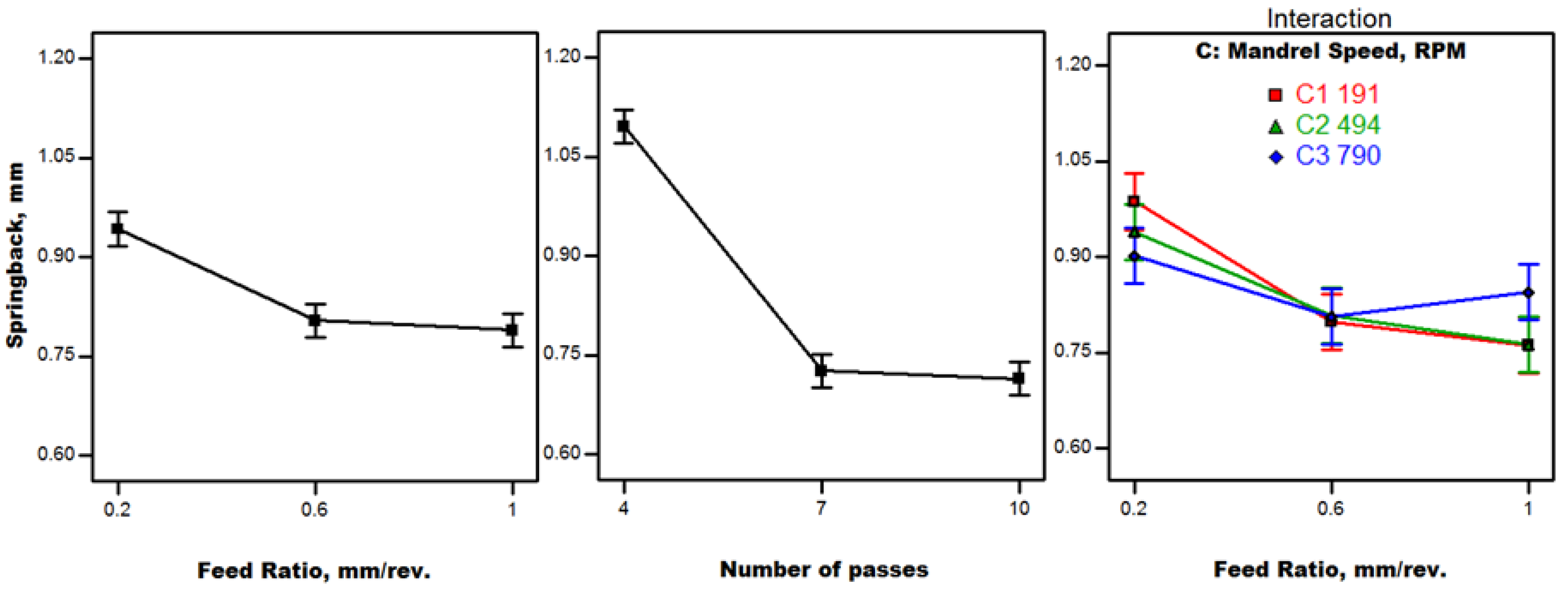
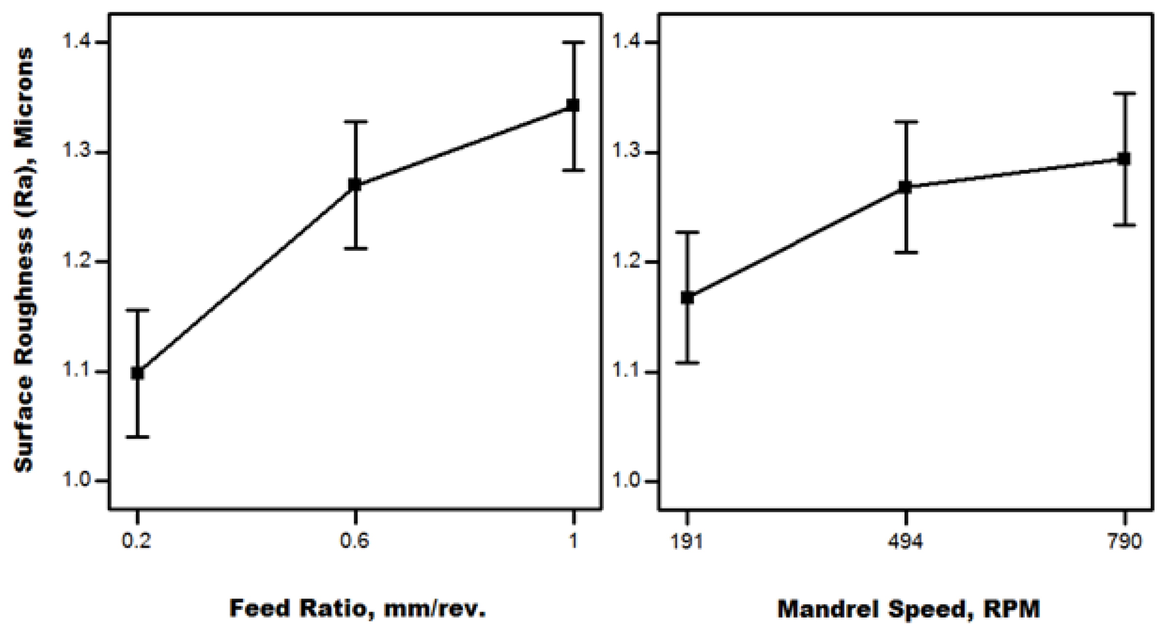
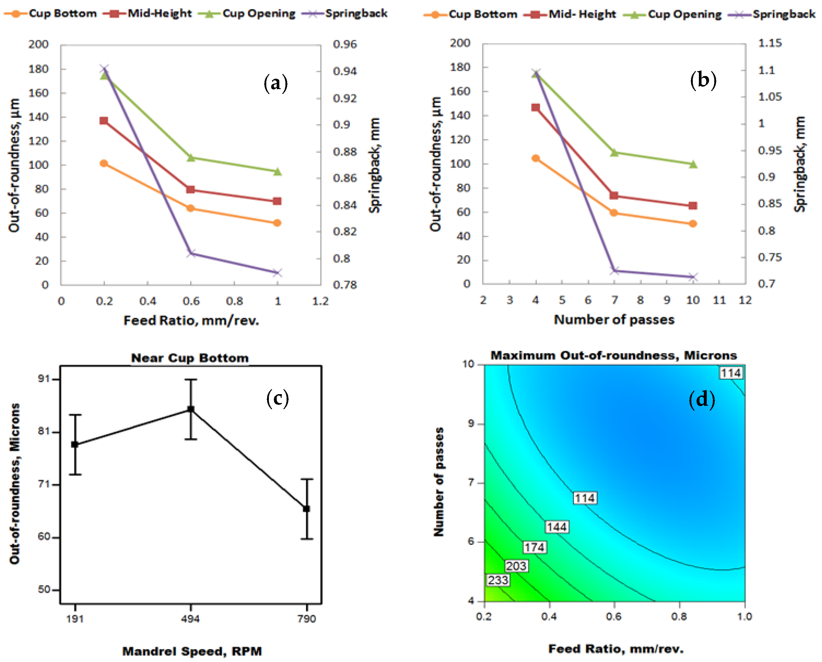
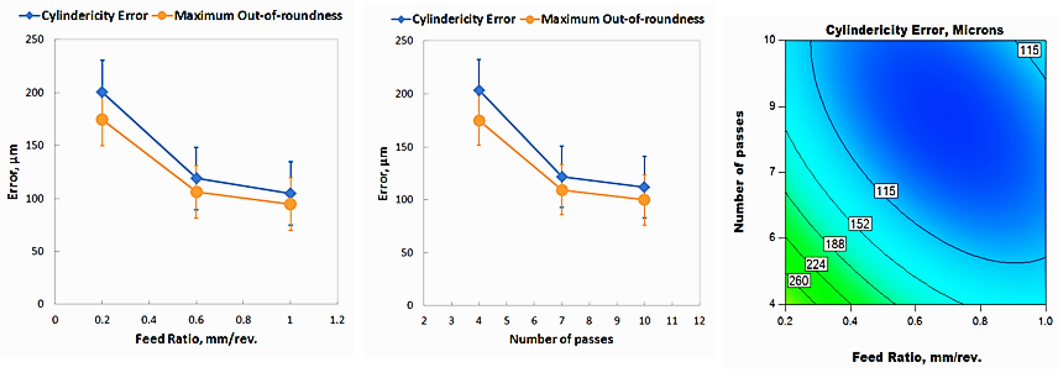
4.2. Results and Discussion

The experimental data of the full factorial design are presented in Appendix B. Significant factors and interactions are demonstrated in Table 5. All considered factors and interactions are significant for both maximum wall thinning and cup height. Only two factors and one interaction are significant for springback, out-of-roundness, and cylindericity error. Surface roughness only has two significant factors. Contrary to the screening experiments results, the feed ratio has a significant effect on all quality characteristics due to the absence of spinning ratio variation, so the influence of the feed ratio is clearer in the second set of experiments. Also, the number of passes has no significant effect on surface roughness due to the use of lubrication and ≤10 passes in all runs, unlike the screening experiment results, where highly repeated contact and friction are dominant (number of passes ≥10).
Maximum wall thinning results are illustrated in Figure 10. The most significant factor is the feed ratio. It is observed that the increase in feed ratio is accompanied by a significant decrease in maximum wall thinning. As mentioned in Section 3.2, this can be attributed to less shearing effect at high feed ratios. The decrease in maximum wall thinning between 0.2 mm/rev. and 0.6 mm/rev. feed ratios is sharp, while less rate of change in thinning is observed between 0.6 and 1 mm/rev. feed ratios. The effect of number of passes on maximum thinning is pronounced for number of passes ≤7. A steep reduction in thinning is noticed as the number of passes increases from four to seven. At a lower number of passes, the deformation rate per pass is high, leading to larger thinning due to higher induced tensile radial stress. As the number of passes increases, the rate of deformation decreases, resulting in less thinning. There is almost no change in the thinning value between seven and 10 passes, although there is a tiny change (higher thinning) at 10 passes due to more repeated deformation. A slight increase in thinning is noticed between mandrel speeds 191 and 494 RPM, while a significant decrease is dominant over 494 RPM, reaching a minimum at 790 RPM. Three significant interactions are represented in Figure 10. Minimum wall thinning is found to be at the maximum feed ratio with maximum spin-forming passes, while maximum thinning is observed at the minimum feed ratio with minimum spin-forming passes. Minimum thinning is noticed at the maximum feed ratio with both mandrel speeds 191 and 790 RPM, while maximum thinning is found to be at the minimum mandrel speed with the minimum feed ratio. Minimum thinning is found to be at seven spin-forming passes with the maximum mandrel speed.
Comparing Figure 10 with Figure 11, it is observed that the cup height trend is almost the same as the maximum wall thinning trend. This suggests a relationship between cup height and wall thinning. The increase in cup height can be attributed to the thinning action accompanied by metal flow in front of the roller in the radial direction towards the cup opening. Thinning of the cup wall is compromised by an increase in cup height to maintain the material volume constant. An experiment was conducted to prove this behavior based on four incremental manufacturing stages of a cup produced using four spin-forming passes, as shown in Figure 12. The wall thickness is reduced after each forward pass. The region of maximum thinning after each pass moves towards the cup opening as the spinning process progresses due to metal flow in the radial direction. It is observed that the radial distance increases after each pass, leading to an overall increase in cup height at the end of the process. The maximum thinning rate is found to be at the final pass due to the sizing effect. Additionally, the material thickness decreases exponentially in the fourth pass compared to the third pass owing to the high tensile deep drawing effect during the fourth pass along with high rate of deformation. As a result, cup height increases as the maximum wall thinning increases. Almost a reverse relationship is pronounced between cup height and the processing parameters. The maximum cup height is achieved at the minimum feed ratio, minimum spin-forming passes, and minimum mandrel rotational speed, while the minimum cup height is found to be at the maximum feed ratio, intermediate spin-forming passes, and maximum mandrel speed.
Springback results are shown in Figure 13. The most significant factor is the number of passes. The results are generally in agreement with the screening experiment results under a lubricated condition. As the feed ratio increases, the springback decreases due to the lower frictional load. Maximum springback is observed at the minimum number of passes due to the higher rate of loading, as mentioned before. A sharp decline of springback is noticed between four and seven spin-forming passes due to the steep fall in loading rate. Only one interaction is significant; between the feed ratio and mandrel speed. Maximum springback is found to be at the minimum mandrel speed and minimum feed ratio due to the lower contact area and then higher stress concentration, leading to more metal flow a under lubricated condition which causes cup diameter expansion due to elastic recovery. Minimum springback is observed at the maximum feed ratio combined with lower mandrel speeds due to higher plastic deformation and less elastic recovery.
Surface roughness results are illustrated in Figure 14. The most significant factor is the feed ratio. Comparing Figure 14 with Figure 6, it is observed that the feed ratio effect is reversed for the range of passes ≤10 (second set of experiments) relative to the range ≥10 passes (screening experiments) and the surface roughness values are considerably lower due to lubrication and the smaller number of passes used. Lower surface roughness is observed for a small feed ratio due to small spaced tool marks. As the feed ratio increases, tool marks are largely spaced and then roughness increases. This is in agreement with the findings obtained by Chen et al. and El-Khabeery et al. [3,25,32]. A similar trend was noticed for the mandrel speed effect on surface roughness. As the mandrel rotational speed increases, surface roughness increases due to the higher rate of deformation, resulting in more surface irregularities, as noticed by Udayani et al. [37]. This behavior is more pronounced at lower mandrel speeds between 191 and 494 RPM.
Out-of-roundness results are illustrated in Figure 15. It is observed that out-of-roundness is higher near the cup opening. This is due to the springback effect, which causes the cup diameter to expand. The expansion in cup diameter is larger towards the open end of the cup. This leads to the increasing trend of out-of-roundness from bottom to opening, as shown in Figure 15a,b. The trend of out-of-roundness is similar to the trend of springback in terms of both the feed ratio and number of passes. As both the feed ratio and number of passes increase, out-of-roundness decreases, which is the same finding for the screening experiments under a lubricated condition, as shown previously in Figure 8. Mandrel rotational speed was found to be significant for the near cup bottom out-of-roundness. Minimum out-of-roundness is observed at the maximum mandrel rotational speed (790 RPM). This is due to the limited effect of the single point roller tool as the mandrel speed increases. The indentation points come closer to each other as the rotational speed increases. There is a fluctuation in the roundness behavior, as shown in Figure 15c, with the maximum roundness error at 494 RPM. The significant interaction between the feed ratio and number of passes is illustrated in the contour plot (Figure 15d). Maximum out-of-roundness (near cup opening) was observed at the minimum feed ratio combined with the minimum number of passes due to the largest rate of deformation and metal flow at this condition.
Cylindericity error results are presented in Figure 16. The cylindericity error trend is similar to the out-of-roundness trend because they are almost controlled by the same conditions. It is found that the values of cylindericity error are larger than that of maximum out-of-roundness of the cups. This suggests a slight curvature in the axis of the cup, which causes such a condition. This can be attributed to the bending action of the single point roller tool, which only makes contact with the workpiece from one side. The contour chart illustrates the significant interaction between the feed ratio and number of passes. Maximum cylindericity error is found at the minimum feed ratio and minimum number of passes.

5. Conclusions

In this investigation, two series of CNC multi-pass spinning experiments were performed in order to study the effect of significant parameters on the geometrical accuracy of produced cups. The following main concluded points can be established:
  • With lubrication, it is possible to obtain minimum cup wall thinning, small springback, more uniform roundness, and cylindericity at a high feed ratio, which implies a high processing speed (productivity) associated with higher quality principally using a larger number of spinning passes. This finding breaks the rule that slow spinning is fundamental to acceptable quality, and assures the prospective features of cutting-edge spinning technology for both large and small size parts.
  • Achieved levels of minimum wall thinning find applicability in high-pressure vessels.
  • Larger product heights are essential for better material utilization in satellite nose cones and can be obtained at a low feed ratio and small number of passes.
  • A compromise between wall thinning and product height is required to optimize both quality characteristics simultaneously.
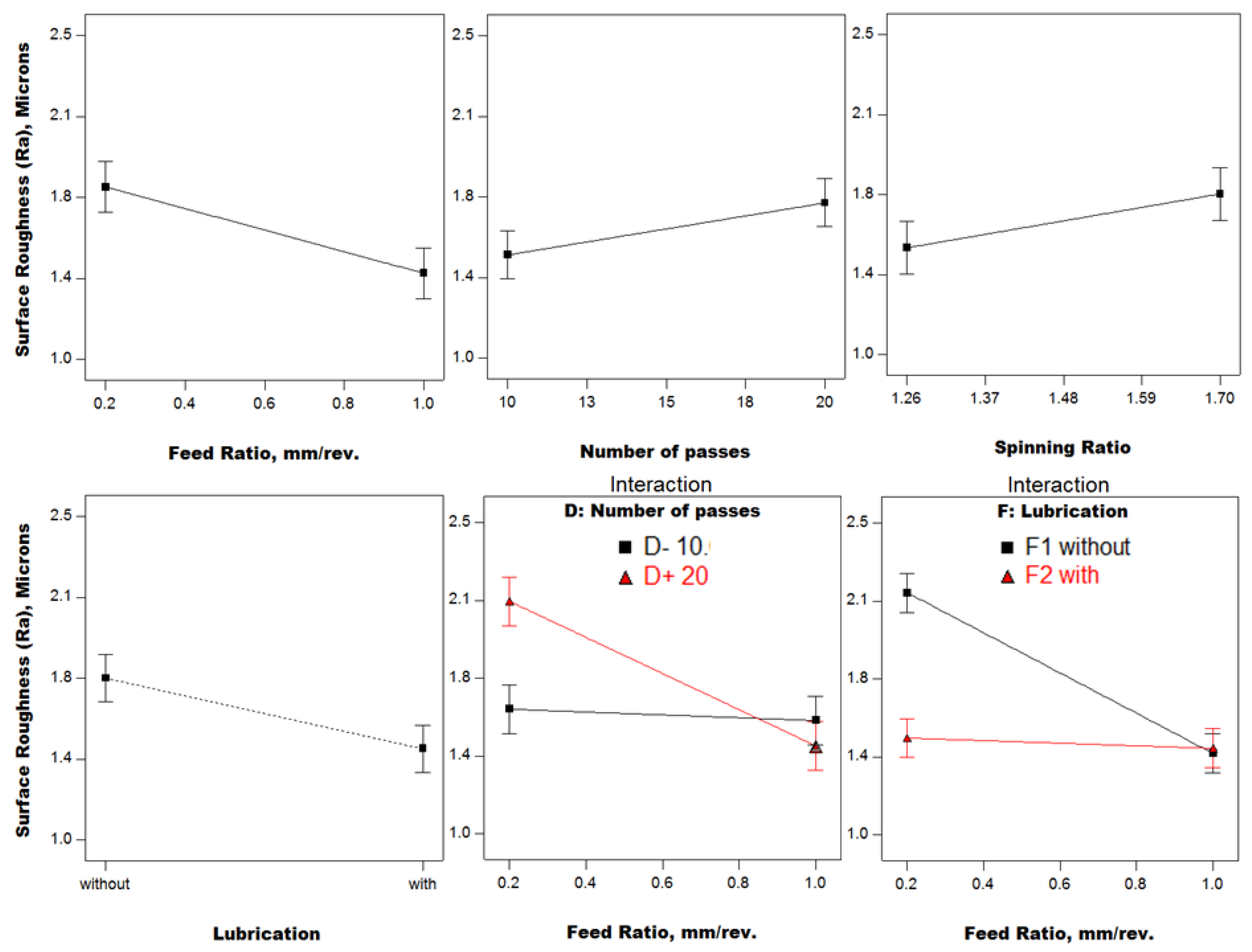
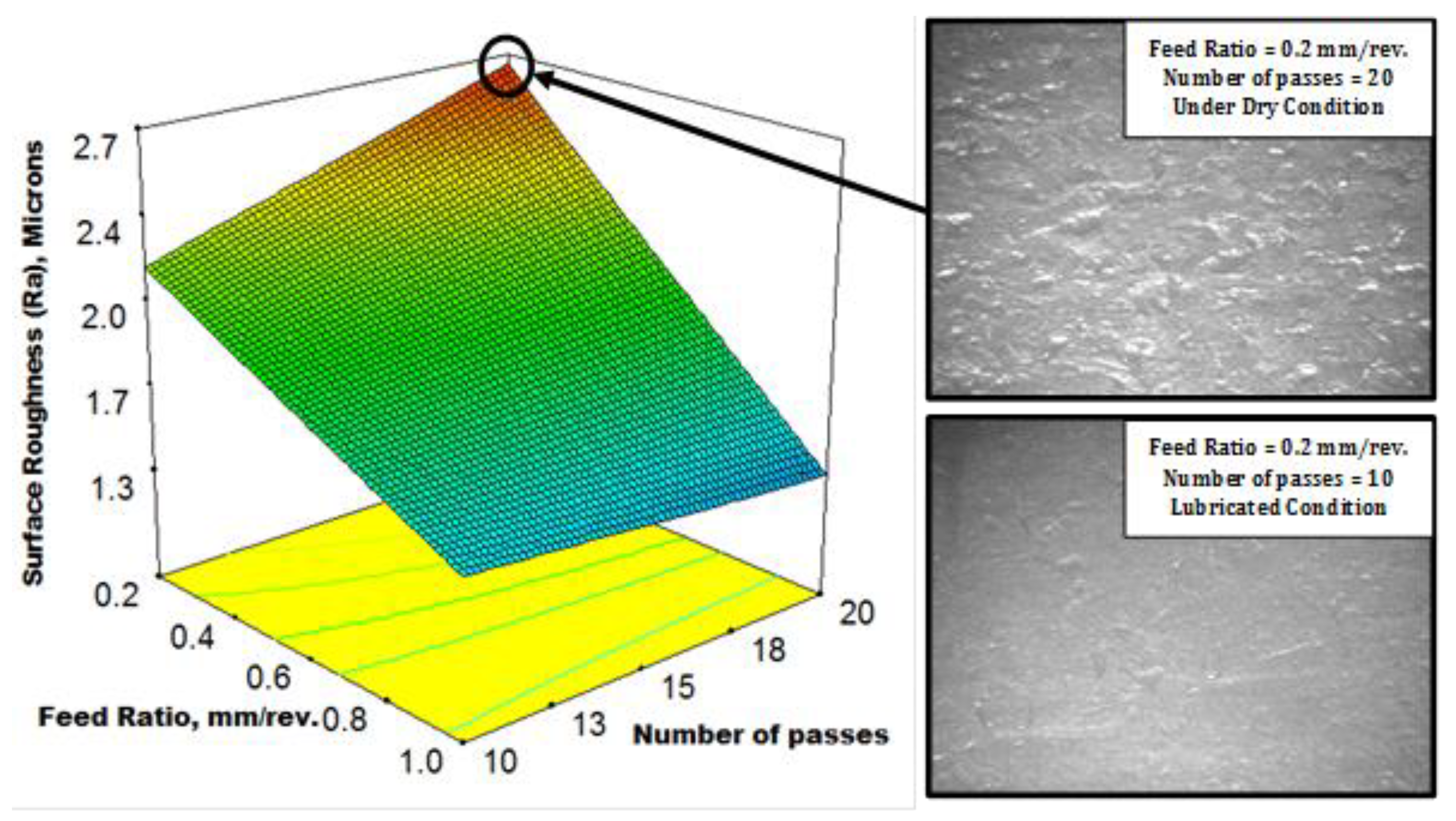
  • Obtained surface finish values are particularly advantageous to aerospace bearing cages, especially at small spinning ratios.
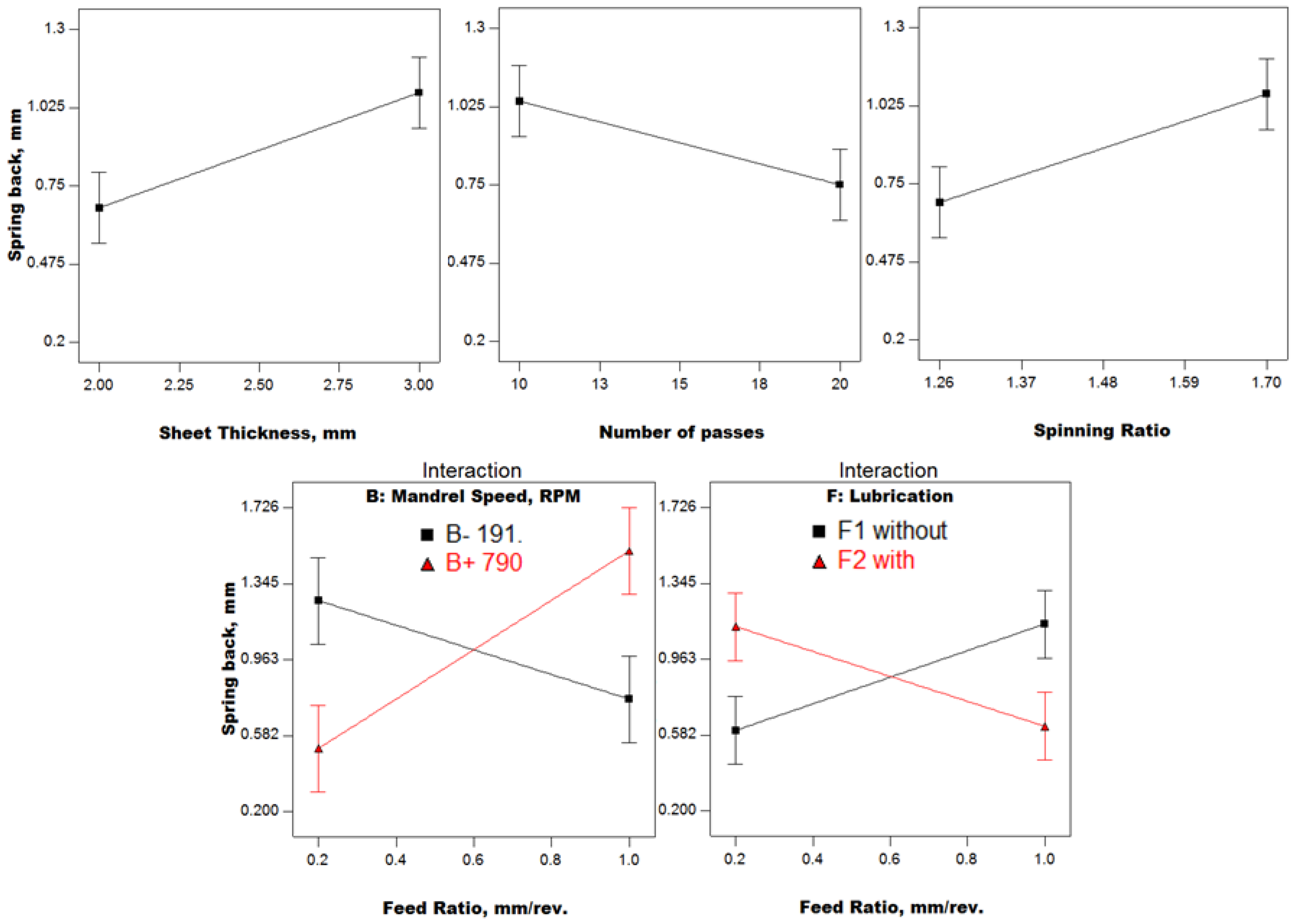
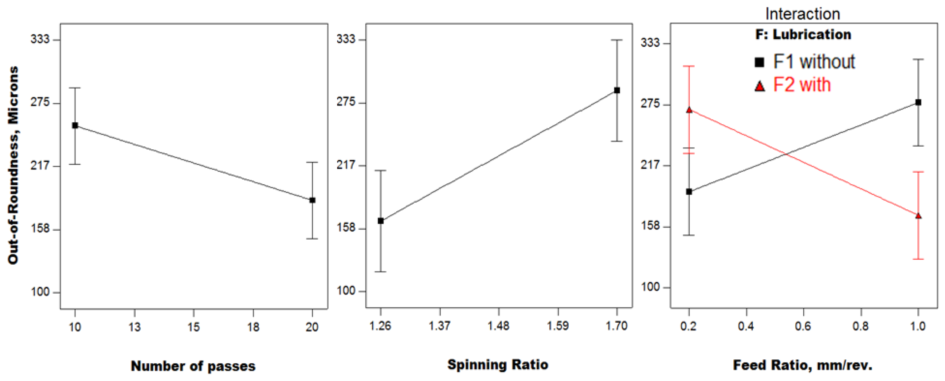
  • There seems to be a direct relationship between springback and roundness of the spun cups due to the sheet metal anisotropy.
  • It is recommended to examine the use of two roller tools on opposite sides for the straightness of the spun cup axis.

Author Contributions

Conceptualization, Funding Acquisition, Project Administration, and Resources: Mahmoud Ahmed; Methodology, Validation, and Data Curation: M.Y. and M.A.-A.; CNC Software, Formal Analysis, Investigation, Visualization, and Writing-Original Draft Preparation: M.A.-A.; Supervision, and Writing-Review & Editing: M.A. and M.Y.

Funding

This research was funded by the Academy of Scientific Research and Technology (EG) grant number Q20.

Acknowledgments

The authors gratefully acknowledge the administrative team in the Faculty of Engineering, Alexandria University, for facilitating the acquisition of pure aluminum blanks used in the experiments.

Conflicts of Interest

The authors declare no conflict of interest. The funders had no role in the design of the study; in the collection, analyses, or interpretation of data; in the writing of the manuscript, and in the decision to publish the results.

Appendix A

Table A1. First Design of Experiments Results.
RunFeed Ratio, mm/rev.Mandrel Speed, RPMSheet Thickness, mmNo. of PassesSpinning RatioLubricationMaximum Thinning%Springback, mmSurface Roughness, μmOut-of-Roundness, μm
117902201.26without11.820.5361.2197
217903101.7without35.112.0211.5304
311912201.7with30.050.6151.3161
40.21913201.7without59.210.8722.7197
517903201.7with28.060.8251.2197
611913201.26without33.070.4991.5132
70.27902101.7with60.90.8281.4472
817903201.7with28.080.4821.5170
917902201.26without9.480.6961.1117
1011912101.7without40.020.8211.4440
110.27902201.7without41.460.2552.6244
1211912201.7with32.51.1151.5193
130.21913101.7with66.021.8451.5363
1411912101.7without39.930.7761.5272
150.21912201.26with32.560.7161.6133
1617902101.26with11.820.4921.3112
170.27903201.26with43.221.7481.5161
180.21912101.26without33.30.7851.3170
190.27903201.26with43.220.6071.4294
200.21913201.7without60.110.8652.7198
2117903101.7without24.792.8831.5588
220.21912101.26without33.520.8192139
230.27902201.7without42.390.2652.6244
240.21912201.26with28.50.6731.4230
2511913101.26with18.750.4711.4146
2611913101.26with16.420.4731.8160
270.27903101.26without36.670.4041.5180
2817902101.26with8.350.5521.5166
290.27902101.7with60.650.8491.7198
300.21913101.7with72.821.7681.3262
3111913201.26without36.480.911.5117
320.27903101.26without39.210.5951.9113

Appendix B

Table A2. Second Design of Experiments Results.
RunFeed Ratio, mm/revNumber of PassesMandrel Speed, RPMMaximum Thinning%Cup Height, mmSpringback, mmSurface Roughness (Ra), μmMaximum Out-of-Roundness, μmCylindericity Error, μm
10.61079017.2333.540.7761.037988
20.21049437.2940.090.9160.93147163
30.61079015.2533.520.6361.29162180
40.6419121.234.780.9361.443247
511019113.6333.650.6171.038797
60.6719113.8333.20.7661.5992102
70.61019116.3933.930.671.28184204
811079012.9632.240.7271.566774
90.21019125.9837.640.7560.99127141
100.61019116.3534.570.6730.936572
1111049413.4233.570.6891.447795
120.21019128.0637.60.8081.26114127
130.2779020.3334.440.7621.38392
1411079012.5432.820.61.448190
151419115.9133.451.0361.38161179
160.2719128.4437.230.8911166184
170.21079025.9837.970.7431.086077
180.6779013.8333.120.7041.246774
1911049414.234.280.6151.256370
201101916.4732.430.7331.55137152
211419115.733.740.9631.4568119
221719113.9634.110.6251.03137152
230.61049413.533.830.7541.388493
240.6449423.1934.810.9651.21139154
250.2479036.9237.981.2021.15292324
261449425.3435.461.0481.2149165
270.2449437.6837.81.1381.5356396
280.6419128.0236.041.0771.23112124
290.2779022.2935.250.7221.13162180
301719116.4733.760.5981.247988
310.61049418.2335.570.6341.1127141
320.6749420.4135.730.6561.31112124
330.21049430.5638.980.7740.91104116
340.2749425.0535.970.8891.288999
351749417.99360.4741.39104116
360.2749427.9237.610.811.06117130
370.6749418.2733.870.7641.5117130
381449427.8836.61.1571.15104116
390.2449430.1536.591.111.49311345
400.2479041.6340.41.2461.05248275
411479020.7935.091.0041.44113125
421479018.3134.121.0791.61177197
430.2419152.1143.031.4110.78390443
440.6449422.8934.461.0731.45158175
45177909.0532.70.6971.48112124
460.21079027.2236.980.7321.08126140
470.6779016.9933.660.6951.217988
480.6479028.0935.741.0591.48127141
49177908.8731.890.961.4393103
500.2419147.3441.511.2580.78160273
510.2719128.0936.510.7971.0893103
520.6719119.6734.890.671.03124138
530.6479015.8233.360.9651.335965
541749418.0334.620.591.29148164

References

  1. Essa, K. Finite Element Prediction of Deformation Mechanics in Incremental Forming Processes. Ph.D. Thesis, University of Birmingham, Birmingham, UK, 2011. [Google Scholar]
  2. Wang, L. Analysis of Material Deformation and Wrinkling Failure in Conventional Metal Spinning Process. Ph.D. Thesis, Durham University, Durham, UK, 2012. [Google Scholar]
  3. Chen, M.-D.; Hsu, R.-Q.; Fuh, K.-H. Effects of over-roll thickness on cone surface roughness in shear spinning. J. Mater. Process. Technol. 2005, 159, 1–8. [Google Scholar] [CrossRef]
  4. Kong, Q.; Yu, Z.; Zhao, Y.; Wang, H.; Lin, Z. Theoretical prediction of flange wrinkling in first-pass conventional spinning of hemispherical part. J. Mater. Process. Technol. 2017, 246, 56–68. [Google Scholar] [CrossRef]
  5. Kong, Q.; Yu, Z.; Zhao, Y.; Wang, H.; Lin, Z. A study of severe flange wrinkling in first-pass conventional spinning of hemispherical part. Int. J. Adv. Manuf. Technol. 2017, 91, 1–16. [Google Scholar] [CrossRef]
  6. Polyblank, J.A.; Allwood, J.M. Parametric toolpath design in metal spinning. CIRP Ann. Manuf. Technol. 2015, 64, 301–304. [Google Scholar] [CrossRef]
  7. Rentsch, B.; Manopulo, N.; Hora, P. Numerical modelling, validation and analysis of multi-pass sheet metal spinning processes. Int. J. Mater. Form. 2017, 10, 641–651. [Google Scholar] [CrossRef]
  8. Wong, C.C.; Dean, T.A.; Lin, J. A review of spinning, shear forming and flow forming processes. Int. J. Mach. Tools Manuf. 2003, 43, 1419–1435. [Google Scholar] [CrossRef]
  9. Music, O.; Allwood, J.M.; Kawai, K. A review of the mechanics of metal spinning. J. Mater. Process. Technol. 2010, 210, 3–23. [Google Scholar] [CrossRef]
  10. Xiao, Y.; Han, Z.; Fan, Z.; Jia, Z. A study of asymmetric multi-pass spinning for angled-flange cylinder. J. Mater. Process. Technol. 2018, 256, 202–215. [Google Scholar] [CrossRef]
  11. Gan, T.; Yu, Z.; Zhao, Y.; Evsyukov, S.A.; Lai, X. Effects of backward path parameters on formability in conventional spinning of aluminum hemispherical parts. Trans. Nonferrous Met. Soc. China 2018, 28, 328–339. [Google Scholar] [CrossRef]
  12. Xia, Q.; Shima, S.; Kotera, H.; Yasuhuku, D. A study of the one-path deep drawing spinning of cups. J. Mater. Process. Technol. 2005, 159, 397–400. [Google Scholar] [CrossRef]
  13. Wang, L.; Long, H.; Ashley, D.; Roberts, M.; White, P. Effects of the roller feed ratio on wrinkling failure in conventional spinning of a cylindrical cup. Proc. Inst. Mech. Eng. Part B J. Eng. Manuf. 2011, 225, 1991–2006. [Google Scholar] [CrossRef] [Green Version]
  14. Ma, F.; Yang, H.; Zhan, M. Plastic deformation behaviors and their application in power spinning process of conical parts with transverse inner rib. J. Mater. Process. Technol. 2010, 210, 180–189. [Google Scholar] [CrossRef]
  15. Fazeli, A.R.; Ghoreishi, M. Statistical analysis of dimensional changes in thermomechanical tube-spinning process. Int. J. Adv. Manuf. Technol. 2011, 52, 597–607. [Google Scholar] [CrossRef]
  16. Wang, L.; Long, H. Roller path design by tool compensation in multi-pass conventional spinning. Mater. Des. 2013, 46, 645–653. [Google Scholar] [CrossRef]
  17. Essa, K.; Hartley, P. Optimization of conventional spinning process parameters by means of numerical simulation and statistical analysis. Proc. Inst. Mech. Eng. Part B J. Eng. Manuf. 2010, 224, 1691–1705. [Google Scholar] [CrossRef] [Green Version]
  18. Kang, D.-C.; Gao, X.-C.; Meng, X.-F.; Wang, Z.-H. Study on the deformation mode of conventional spinning of plates. J. Mater. Process. Technol. 1999, 91, 226–230. [Google Scholar] [CrossRef]
  19. Liu, J.H.; Yang, H.; Li, Y.Q. A study of the stress and strain distributions of first-pass conventional spinning under different roller-traces. J. Mater. Process. Technol. 2002, 129, 326–329. [Google Scholar] [CrossRef]
  20. Wang, L.; Long, H. Investigation of material deformation in multi-pass conventional metal spinning. Mater. Des. 2011, 32, 2891–2899. [Google Scholar] [CrossRef]
  21. Wang, L.; Long, H. A study of effects of roller path profiles on tool forces and part wall thickness variation in conventional metal spinning. J. Mater. Process. Technol. 2011, 211, 2140–2151. [Google Scholar] [CrossRef]
  22. Essa, K.; Hartley, P. Numerical simulation of single and dual pass conventional spinning processes. Int. J. Mater. Form. 2009, 2, 271–281. [Google Scholar] [CrossRef]
  23. Sugita, Y.; Arai, H. Formability in synchronous multipass spinning using simple pass set. J. Mater. Process. Technol. 2015, 217, 336–344. [Google Scholar] [CrossRef]
  24. Šugár, P.; Šugárová, J.; Petrovič, J. Analysis of the Effect of Process Parameters on Part Wall Thickness Variation in Conventional Metal Spinning of Cr-Mn Austenitic Stainless Steels. Stroj. Vestn. J. Mech. Eng. 2016, 62, 171–178. [Google Scholar] [CrossRef] [Green Version]
  25. EL-Khabeery, M.M.; Fattouh, M.; EL-Sheikh, M.N.; Hamed, O.A. On the Conventional Simple Spinning of Cylindrical Aluminium Cups. Int. J. Mach. Tools Manuf. 1991, 31, 203–219. [Google Scholar] [CrossRef]
  26. Kawai, K.; Yang, L.-N.; Kudo, H. A flexible shear spinning of axi-symmetrical shells with a general-purpose mandrel. J. Mater. Process. Technol. 2007, 192–193, 13–17. [Google Scholar] [CrossRef]
  27. Venkateshwarlu, G.; Kumar, K.R.; Reddy, T.A.J.; Gopi, G. Experimental Investigation on Spinning of Aluminum Alloy 19500 Cup. Int. J. Eng. Sci. Innov. Technol. 2013, 2, 357–363. [Google Scholar]
  28. Dong, H.; Mei, Z.; He, Y. Deformation Mechanism of TA15 Shells in Hot Shear Spinning under Various Load Conditions. Rare Met. Mater. Eng. 2013, 42, 243–248. [Google Scholar]
  29. Polyblank, J.A.; Allwood, J.M. Support roller control and springback compensation in flexible spinning. Procedia Eng. 2014, 81, 2499–2504. [Google Scholar] [CrossRef]
  30. Liu, C.-H. The simulation of the multi-pass and die-less spinning process. J. Mater. Process. Technol. 2007, 192–193, 518–524. [Google Scholar] [CrossRef]
  31. Marghmaleki, I.S.; Beni, Y.T.; Noghrehabadi, A.R.; Kazemi, A.S.; Abadyan, M. Finite Element Simulation of Thermomechanical Spinning Process. Procedia Eng. 2011, 10, 3769–3774. [Google Scholar] [CrossRef]
  32. Chen, M.-D.; Hsu, R.-Q.; Fuh, K.-H. Forecast of shear spinning force and surface roughness of spun cones by employing regression analysis. Int. J. Mach. Tools Manuf. 2001, 41, 1721–1734. [Google Scholar] [CrossRef]
  33. Fazeli, A.R.; Ghoreishi, M. Investigation of effective parameters on surface roughness in thermomechanical tube spinning process. Int. J. Mater. Form. 2009, 2, 261–270. [Google Scholar] [CrossRef]
  34. Chen, M.-D.; Hsu, R.-Q.; Fuh, K.-H. An analysis of force distribution in shear spinning of cone. Int. J. Mech. Sci. 2005, 47, 902–921. [Google Scholar] [CrossRef]
  35. Kleiner, M.; Ewers, R.; Kunert, J.; Henkenjohann, N.; Auer, C. Optimisation of the Shear Forming Process by Means of Multivariate Statistical Methods. 2005. Available online: http://www.statistik.tu-dortmund.de/fileadmin/user_upload/Lehrstuehle/MSind/SFB_475/2005/tr23-05.pdf (accessed on 17 August 2014).
  36. Jaromír, A. Spinning Force Characteristics in Forming Steel Blanks. Transf. Inovácií 2007, 10, 230–234. [Google Scholar]
  37. Udayani, K.; Veeranna, V.; Gajanana, S.; Reddy, K.H. Optimization of Process Parameters of Metal Spinning using Response Surface Methodology. Int. J. Emerg. Technol. Eng. Res. 2017, 5, 253–256. [Google Scholar]
  38. Kawai, K.; Yang, L.-N.; Kudo, H. A flexible shear spinning of truncated conical shells with a general-purpose mandrel. J. Mater. Process. Technol. 2001, 113, 28–33. [Google Scholar] [CrossRef]
  39. Razani, N.A.; Aghchai, A.J.; Dariani, B.M. Experimental study on flow forming process of AISI 321 steel tube using the Taguchi method. Proc. Inst. Mech. Eng. Part B J. Eng. Manuf. 2011, 225, 2024–2031. [Google Scholar] [CrossRef]
  40. Imamura, Y.; Ikawa, K.; Sakane, Y.; Iwasaki, H.; Hirakawa, T. Investigation of forming accuracy in mandrel-free hot-spinning. Procedia Eng. 2017, 207, 1701–1706. [Google Scholar] [CrossRef]
  41. Valoppi, B.; Egea, A.J.S.; Zhang, Z.; Rojas, H.A.G.; Ghiotti, A.; Bruschi, S.; Cao, J. A hybrid mixed double-sided incremental forming method for forming Ti6Al4V alloy. CIRP Ann. Manuf. Technol. 2016, 65, 309–312. [Google Scholar] [CrossRef] [Green Version]
Figure 1. Experimental setup.
Jmmp 02 00059 g001
Figure 2. Screening experiments’ roller path profiles: (a) Spinning ratio = 1.26 and 10 passes; (b) Spinning ratio = 1.26 and 20 passes; (c) Spinning ratio = 1.7 and 10 passes; (d) Spinning ratio = 1.7 and 20 passes.
Jmmp 02 00059 g002
Figure 3. Measurement points on spun cups.
Jmmp 02 00059 g003
Figure 4. Maximum thinning results (Phase I).
Jmmp 02 00059 g004
Figure 5. Springback results (Phase I).
Jmmp 02 00059 g005
Figure 6. Surface roughness results (Phase I).
Jmmp 02 00059 g006
Figure 7. Severe surface condition (roughening and tearing of the surface).
Jmmp 02 00059 g007
Figure 8. Out-of-roundness results (Phase I).
Jmmp 02 00059 g008
Figure 9. Full factorial experiments’ roller path profiles: (a) Spinning ratio = 1.26 and 4 passes; (b) Spinning ratio = 1.26 and 7 passes.
Jmmp 02 00059 g009
Figure 10. Maximum thinning results (Phase II).
Jmmp 02 00059 g010
Figure 11. Cup height results.
Jmmp 02 00059 g011
Figure 12. Wall thickness and radial distance variation after each forward pass: (a) Incremental stages; (b) Thickness distributions.
Jmmp 02 00059 g012
Figure 13. Springback results (Phase II).
Jmmp 02 00059 g013
Figure 14. Surface roughness results (Phase II).
Jmmp 02 00059 g014
Figure 15. Out-of-roundness results (Phase II). (a) Effect of feed ratio; (b) Effect of number of passes; (c) Effect of mandrel speed near cup bottom; (d) Interaction plot between feed ratio and number of passes.
Jmmp 02 00059 g015
Figure 16. Cylindericity error results.
Jmmp 02 00059 g016
Table 1. Chemical composition of the aluminum blanks.
ElementsAlSiFeCuZnNiSnTipOthers
Weight (%)99.50.1270.1990.0030.0260.0120.0220.059<0.0010.051
Table 2. Screening experiments’ factors and levels.
FactorsLevels
Feed Ratio (mm/rev.)0.21
Mandrel Speed (RPM)191790
Sheet Thickness (mm)23
Number of passes1020
Spinning Ratio1.261.7
Lubricationwithoutwith
Table 3. Screening design significant factors and interactions with p-values.
FactorsMaximum ThinningSpringbackSurface RoughnessOut-of-Roundness
Feed Ratio (A)<0.0001x<0.0001x
Mandrel Speed (B)<0.0001xxx
Sheet Thickness (C)<0.00010.0006xx
Number of Passes (D)0.01940.00730.00740.0205
Spinning Ratio (E)<0.00010.0010.00060.0002
Lubrication (F)xx<0.0001x
Interactions
AxBx0.002xx
AxD0.0003x<0.0001x
AxExx0.0031x
AxF<0.0001<0.0001<0.00010.0026
BxF<0.0001xxx
Table 4. Full factorial experiments’ factors and levels.
FactorsLevels
Feed Ratio (mm/rev.)0.20.61
Number of Passes4710
Mandrel Speed (RPM)191494790
Table 5. Full factorial significant factors and interactions with p-values.
FactorsMaximum ThinningCup HeightSpringbackSurface RoughnessOut-of-RoundnessCylindericity Error
Feed Ratio (A)<0.0001<0.0001<0.00010.0004<0.0001<0.0001
Number of passes (B)<0.0001<0.0001<0.0001x<0.0001<0.0001
Mandrel Speed (C)0.01090.0009x0.0403xx
Interactions
AxB0.00520.0017xx<0.0001<0.0001
AxC0.01230.01750.0387xxx
BxC0.04250.0103xxxx

