Article

PCD Tool Wear Mechanism and Prediction in Laser–Ultrasonic Synergistic Milling of High-Volume-Fraction SiCp/Al Composites

1
Henan Province Engineering Research Center of Ultrasonic Technology Application, Pingdingshan University, Pingdingshan 467000, China
2
School of Mechanical Engineering, Guizhou Institute of Technology, Guiyang 550025, China
3
School of Mechanical and Power Engineering, Henan Polytechnic University, Jiaozuo 454000, China
*
Authors to whom correspondence should be addressed.
J. Manuf. Mater. Process. 2026, 10(8), 305; https://doi.org/10.3390/jmmp10080305
Submission received: 22 July 2026 / Revised: 14 August 2026 / Accepted: 18 August 2026 / Published: 19 August 2026

Abstract

To address severe PCD tool wear during the milling of high-volume-fraction SiCp/Al composites, a synergistic milling process coupling pulsed laser pretreatment with ultrasonic vibration was proposed. Five-factor, four-level orthogonal experiments were conducted on 70 vol.% SiCp/Al composites to investigate the effects of milling speed, feed per tooth, cutting depth, laser power, and ultrasonic amplitude on milling forces and tool wear, and a tool wear prediction model was established. The results showed that the factors influencing tool wear, in descending order, were feed per tooth, cutting depth, milling speed, laser power, and ultrasonic amplitude. Appropriate laser power and ultrasonic amplitude reduced cutting loads and suppressed tool wear. The model achieved a coefficient of determination of 0.7887 and was statistically significant overall. The optimal parameter combination was 50 m/min, 0.02 mm/z, 0.1 mm, 60 W, and 3.5 μm, under which the tool wear loss was 1.0 mg, representing a reduction of 61.54% compared with the maximum-wear condition. The main wear modes of the PCD tool included rake-face grooving and fatigue spalling, flank-face abrasive wear, and cutting-edge micro-chipping. These findings provide a useful reference for the precision milling of SiCp/Al composites.

1. Introduction

Particle-reinforced silicon carbide aluminum matrix (SiCp/Al) composites integrate the favorable ductility of the aluminum matrix with the high strength and high hardness of SiC reinforcing particles, presenting broad application prospects in aerospace, new energy vehicles, and other industries [1,2,3,4]. High-volume-fraction SiCp/Al composites have significant application potential in the design of high-performance components, such as aero-engine pistons, spacecraft shells, and electronic packaging components, owing to their lightweight performance, excellent dimensional stability, and outstanding wear resistance. Cui et al. [5] systematically investigated the application value of high-volume-fraction SiCp/Al composites for space optical structures. Nevertheless, these materials are classified as typical difficult-to-cut materials. During cutting operations, hard SiC particles induce severe abrasive wear, whereas the inherent plasticity of the Al matrix triggers adhesive wear. The residual stress concentration at the particle–matrix interface further exacerbates both wear mechanisms [6,7]. Accordingly, the effective reduction in the cutting force, mitigation of tool wear, and improvement of the machined surface quality are the key technical bottlenecks restricting the large-scale industrialization of SiCp/Al composites.
The significant difference in mechanical properties between SiC particles and the aluminum matrix can readily induce matrix plastic deformation, particle fracture, interfacial debonding, and cutting-edge micro-chipping during machining. Huang et al. [8] investigated the scratching removal mechanism of 4H-SiC through experiments and molecular dynamics simulations, revealing the transition behavior among different deformation modes. Lin et al. [9] examined PCD tool wear during the machining of SiCp/6005Al composites and found that tool wear increased cutting forces and temperatures while degrading surface integrity. Wang et al. [10] summarized the abrasive, adhesive, and tribochemical wear mechanisms of PCD tools, noting that the dominant wear mode is affected by process parameters, tool geometry, and cooling and lubrication conditions. Grigoriev et al. [11] investigated the influence of tool surface conditions on tool life during the machining of nickel-based superalloys, providing a reference for understanding tool failure behavior. Zhang et al. [12] investigated PCD tool wear during the ultrasonic vibration milling of SiCp/Al composites under supercritical CO2 minimum-quantity lubrication, established a tool wear prediction model, and optimized the cutting parameters. Through finite-element simulations and experiments, Yu et al. [13] found that increasing the cutting depth aggravated cutting forces, subsurface damage, and surface defects. Zhou et al. [14] developed a finite-element model of ultrasonic vibration-assisted cutting and analyzed particle failure and temperature-field variations. Ali et al. [15] established a cutting-force model using response surface methodology and identified cutting depth and feed rate as the primary influencing factors. Sun et al. [16] reviewed laser-assisted machining technologies and reported that laser-induced thermal effects can soften the aluminum matrix and weaken its constraint on SiC particles, thereby improving material machinability. Eshelby et al. [17] established a theoretical framework based on dislocation equilibrium, providing a foundation for understanding material deformation. Zheng et al. [18] employed orthogonal experiments to investigate the effects of ultrasonic vibration-assisted grinding parameters on surface topography. Ji et al. [19] developed a kinematic model for axial ultrasonic vibration-assisted milling and revealed that periodic tool–workpiece separation reduces cutting heat and particle fracture. Fan et al. [20] found that ultrasonic vibration can alleviate dislocation pile-up and suppress interfacial cracking, particle debonding, and particle fracture. Zhao et al. [21] established a milling force model for high-volume-fraction SiCp/Al composites and analyzed the effects of tool nose radius on cutting forces and surface damage. Fan et al. [22] demonstrated that void evolution, crack propagation, and SiC particle failure are major causes of chip and machined surface defects. Sun et al. [23] validated their model through finite-element simulations and PCD tool milling experiments and found that cutting depth significantly affected the cutting forces.
In summary, this study addresses the challenges of high-efficiency and low-damage machining of high-volume-fraction SiCp/Al composites and proposes a novel assisted milling process that integrates pulsed laser thermal softening treatment and tool ultrasonic vibration technology. A collaborative experimental platform that integrates laser heating and ultrasonic vibration was established. The influence of process parameters on the temperature distribution in the cutting zone, milling force, and wear behavior of PCD tools was systematically investigated, and the micro-wear mechanism of cutting tools during synergistic machining with laser thermal softening and ultrasonic vibration was revealed. This study is expected to provide a theoretical foundation and technical support for the high-efficiency precision machining of such composite materials.

2. Materials and Methods

2.1. Materials and Experimental Equipment

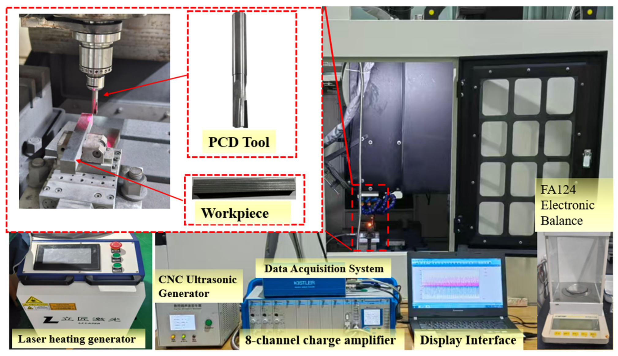
In this experiment, 70 vol.% SiCp/Al composite material was adopted, whose physical properties are listed in Table 1. The machining center employed for the tests was an HFM-600V model (Guizhou Xingfuxiang Leader Grinding Machinery Co., Ltd., Qiandongnan Miao and Dong Autonomous Prefecture, China), as illustrated in Figure 1. A PCD circular end mill with two cutting edges was used as the cutting tool, featuring a diameter of 8 mm, cutting-edge length of 6 mm, and overall tool length of 75 mm. The milling force signals were acquired using a Kistler 9119AA2 dynamometer (Swiss Kistler Instruments Co., Ltd., Winterthur, Switzerland, the milling force-acquisition system type 9119AA2, and the signal amplifier type 5080A). To optimize the material machinability and elevate the cutting efficiency, a laser device was deployed for local preheating of the workpiece surface. After activating the laser equipment, high-power-density laser beams were precisely irradiated onto the target zone, which instantaneously raised the local temperature to reduce the yield strength of the composite and suppress the work hardening during machining. The multi-energy-field-assisted milling platform, which integrates laser and ultrasonic vibration, consists of a pulsed laser generator and an ultrasonic vibration subsystem.

2.2. Experimental Scheme Design

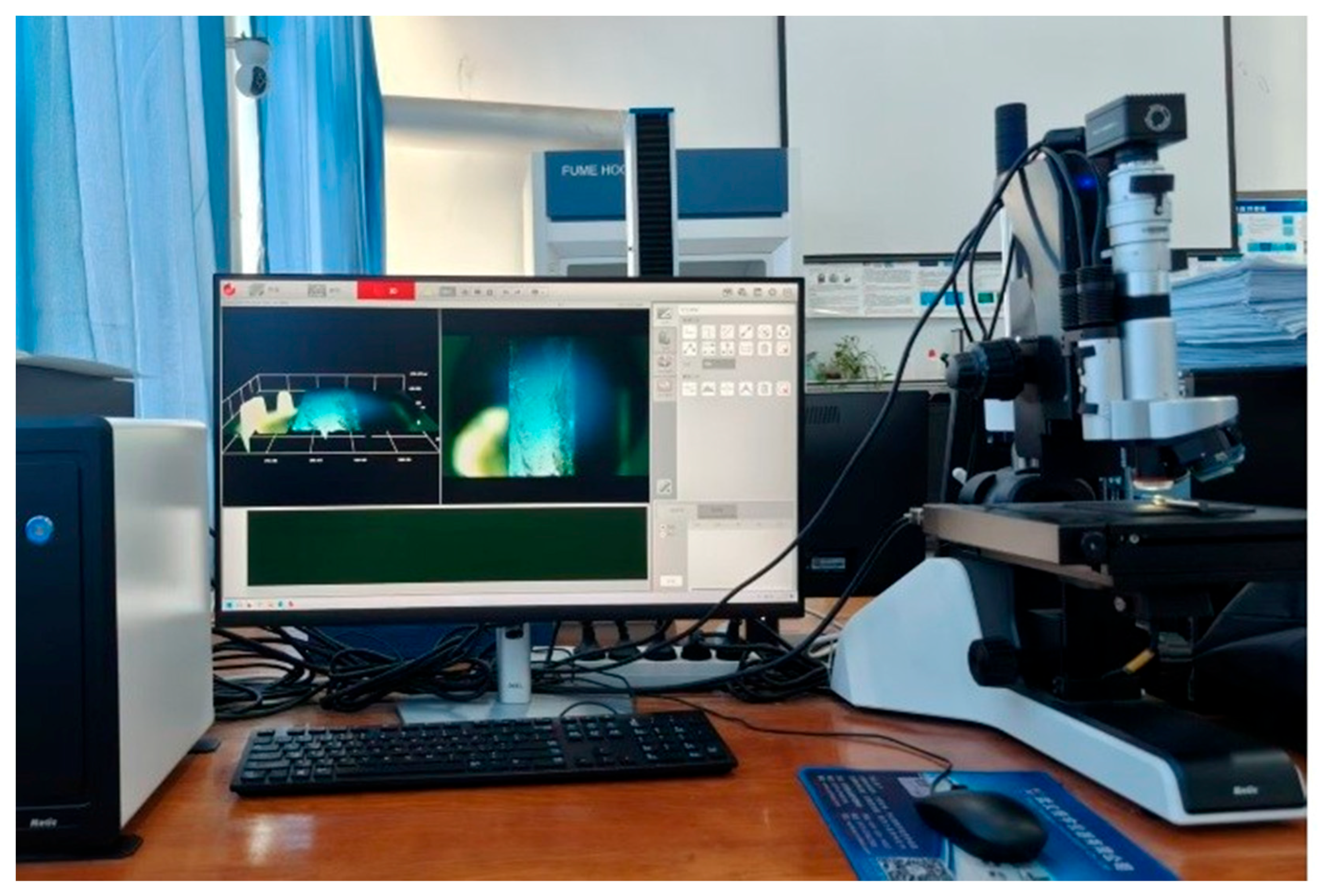
In the present study, milling speed, feed per tooth, cutting depth, laser power, and ultrasonic amplitude were considered as variable factors to explore their influence mechanisms on PCD tool surface wear and milling forces. Sixteen sets of orthogonal tests were arranged based on the orthogonal design method, as shown in Table 2. Specific-level values within the preset range were assigned to each factor. A high-precision electronic balance was used to measure the mass change in the cutting tool, and the actual tool wear loss was calculated by comparing the measured mass with that of the initial state [24]. Each experimental condition was repeated three times, and the mean of the three measurements was used as the final result. To further observe the evolution of the micromorphology, verification experiments were performed using the optimal process parameters. An EasyZoom 5 ultra-high-resolution microscope, as shown in Figure 2, was used to conduct a detailed microscopic imaging analysis of the wear morphology of the tool working surface.

3. Results

The cumulative milling stroke for each test group was set to 10,000 mm, and the results of the orthogonal tests are presented in Table 3.

3.1. Influences of Milling Parameters on Milling Forces

To reveal the inherent mechanism through which milling parameters affect the milling forces, single-factor experiments were conducted in this study. The baseline experimental parameters were set as follows: milling speed of 100 m/min, feed per tooth of 0.04 mm/z, cutting depth of 0.1 mm, constant laser power of 60 W, and ultrasonic amplitude of 3.0 μm. All other variables were maintained within the ranges defined in the orthogonal experiments. For this paper, DynoWare (Version 3.1.0) simulation software was adopted to acquire the experimental data of three-axis milling forces. Intense and periodic fluctuations of milling forces are generated due to the mutual collision and friction between the cutting tool and workpiece. To eliminate the adverse effects of external disturbances, the arithmetic mean value of the relatively stable segment of force signals is calculated for denoising. Specifically, the tangential force Fx acts along the cutting direction, the feed force Fy is perpendicular to the cutting plane and points to the feed direction, and the axial force Fz is parallel to the spindle axis. The resultant force can be calculated using Equation (1):
F e = F x 2 + F y 2 + F z 2

3.1.1. Effects of Milling Speed on Milling Forces

Increasing the milling speed substantially raises the contact frequency between the cutting tool and workpiece, which further leads to a sharp temperature increase in the cutting zone. High temperatures reduce the yield point of matrix materials. Meanwhile, a high heat flux density and high shear velocity generate strong adhesive forces at the contact interface between the workpiece surface and the tool. Under these conditions, the tool wear exhibits complex nonlinear characteristics. Spline cutting tests performed on SiCp-reinforced aluminum matrix composites revealed that severe tool wear occurred at low milling speeds owing to physical abrasion induced by SiC particles. However, at high milling speeds, intensified thermal softening and fluctuating dynamic loads aggravated the degree of tool wear.
In this section, the milling speed is selected as the independent variable, and comparative experiments are conducted to investigate its influence on the milling forces. The milling test parameters are presented in Table 4.
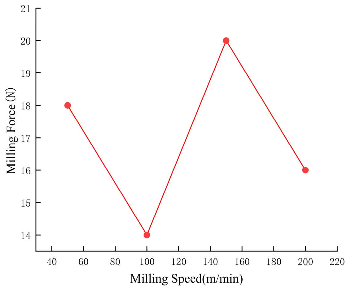
With laser power P fixed at 60 W, cutting depth ap maintained at 0.1 mm, feed per tooth fz kept at 0.04 mm/z, and ultrasonic amplitude A held constant at 3.0 μm, the cutting speed vw was set to 50, 100, 150, and 200 m/min. The variation trends of the milling forces during the laser–ultrasonic multi-energy field cutting of SiCp/Al composites under different milling speeds are presented in Figure 3.
As shown in Figure 3, the milling forces fluctuated with varying cutting speeds during laser–ultrasonic-assisted cutting of SiCp/Al composites, showing an initial gradual decline followed by a sharp rise. The underlying mechanisms are as follows: At low cutting speeds, the transient thermal effect induced by the laser dissipates rapidly, preventing timely chip evacuation and thereby aggravating tool wear. As the cutting speed increases, the laser-affected thermal zone expands to cover the plastic deformation zone, and the rapid material removal rate reduces the milling forces. Further increasing the cutting speed shortens the laser–material interaction duration, which weakens the plastic thermal softening of the workpiece and gradually intensifies the tool wear severity. The experimental results demonstrated that, within a certain range of cutting speeds, the combined laser and ultrasonic composite machining method can effectively suppress tool wear during cutting.

3.1.2. Effects of Feed per Tooth on Milling Forces

The feed per tooth has a remarkable effect on the undeformed chip thickness. Under a low feed per tooth, the cutting tool undergoes both extrusion and sliding during cutting. The superposition of these two effects reduced the material removal volume and increased the repeated friction frequency between the tool edge and SiC particles, accelerating the tool wear. A high feed per tooth increases the thickness of the cutting layer. The resulting high instantaneous loads render the tool more vulnerable to damage, and crushing or pulling out of the reinforcement particles becomes more prominent. Accordingly, the feed per tooth serves as a critical indicator for evaluating tool wear. Its mechanism of action has intricate coupling relationships with other process variables, including milling speed, laser power, and ultrasonic amplitude. It is difficult to fully clarify the actual performance of the system under real working conditions by investigating a single factor in isolation.
In this subsection, the variation characteristics of the tool wear loss at different feed per tooth values are compared to analyze the influence of the parameter. The experimental milling parameters are presented in Table 5.
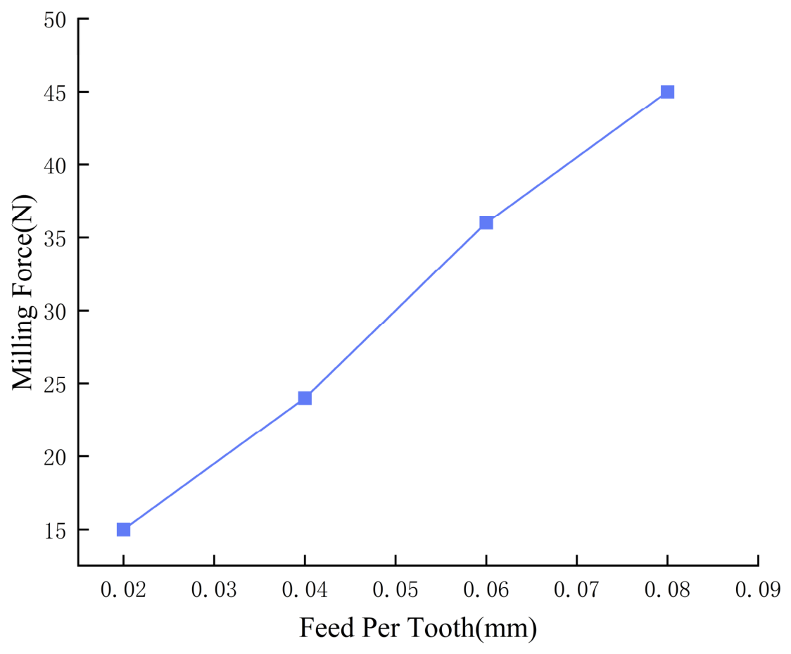
With laser power P fixed at 60 W, cutting depth ap maintained at 0.1 mm, milling speed vw held at 100 m/min, and ultrasonic amplitude A kept constant at 3.0 μm, the feed per tooth fz was set to 0.02 mm/z, 0.04 mm/z, 0.06 mm/z, and 0.08 mm/z, respectively. The variation trend of the milling forces in the laser–ultrasonic multi-energy field cutting of SiCp/Al composites is illustrated in Figure 4.
As shown in Figure 4, the milling force increased with increasing feed per tooth during the laser-induced ultrasonic multi-field coupled milling of SiCp/Al composites. In the initial stage, with a low feed per tooth, sufficient heat conduction time leads to prominent plastic deformation and thermal softening of the workpiece. As the feed per tooth further increased, the transient laser heating duration shortened, which restrained adequate plastic flow and induced strain hardening of the material, thereby increasing the cutting resistance. Meanwhile, the contact area of the cutting edge expands, and more hard SiC particles participate in frictional interactions, accelerating tool wear and resulting in the continuous growth of milling forces. The experimental results demonstrated that the beneficial effect of laser-assisted cutting weakened as the feed per tooth increased.

3.1.3. Influence of Milling Depth Variation on Milling‑Force Responses

As the milling depth increased, the effective cutting-edge length of the tool increased, thereby increasing the material removal rate per unit time. Considering SiCp/Al composites as the research object, a larger milling depth expands the contact area between the tool and SiC particles. This not only aggravated abrasive wear but also induced local damage to the tool flank and cutting edge. A large milling depth hinders the rapid heat dissipation of the cutting heat, increasing the probability of aluminum matrix adhesion to the tool surface.
Systematic research on the effect of cutting depth on milling forces was conducted in this subsection via multi-group comparative experiments. The experimental parameters are presented in Table 6.
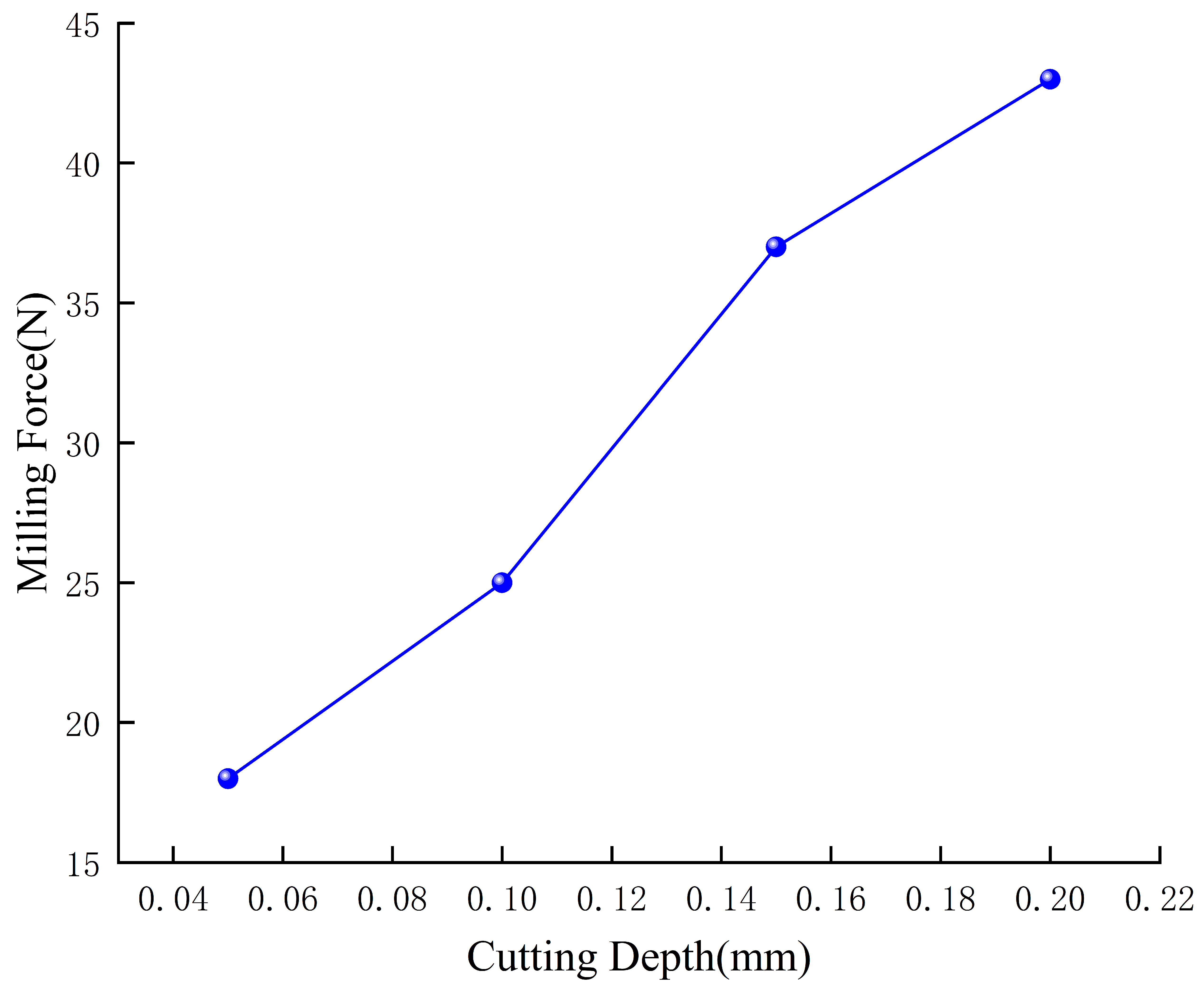
With laser power P fixed at 60 W, milling speed vw maintained at 100 m/min, feed per tooth fz held at 0.04 mm/z, and ultrasonic amplitude A kept constant at 3.0 μm, the cutting depth ap was set to 0.05 mm, 0.1 mm, 0.15 mm, and 0.2 mm. The variation trends of the milling forces during the laser–ultrasonic multi-energy field cutting of the SiCp/Al composites are shown in Figure 5.
As illustrated in Figure 5, the experimental results revealed that the milling force increased monotonically with an increase in the cutting depth during the Laser‑Assisted Machining of SiCp/Al composites. Under identical experimental conditions, the temperature increase on the workpiece surface induced by the laser remained roughly consistent, indicating a stable degree of thermal softening of the material. An increase in the cutting depth resulted in thicker cutting layers. Because the localized thermal effect cannot be uniformly distributed throughout the cutting zone, sufficient plastic deformation cannot be achieved, which consequently increases the milling force. A larger cutting depth expands the effective cutting portion of the tool, and more SiC particles are squeezed into the cutting edge, accelerating tool wear and further increasing the milling forces. Within a certain range of cutting depths, laser-assisted machining can significantly improve the cutting performance and effectively reduce the milling forces.

3.1.4. Effects of Laser Power on Milling Forces

The laser power exerted a bidirectional influence on tool wear. At low laser powers, insufficient plastic deformation fails to achieve effective softening of the cutting layer. When subjected to high hardness and intense friction, the tool suffers rapid and severe wear. When the laser power was gradually increased to an appropriate range, the shear strength of the material decreased significantly, and tool wear was remarkably alleviated. If the power is further increased, excessive thermal softening or local melting of the aluminum matrix occurs, triggering adhesive wear on the rake face, surface thermal damage, and other defects. Therefore, the laser power cannot be regarded as an independent factor affecting tool wear in practical machining. It should be comprehensively analyzed in conjunction with other relevant process parameters.
In this subsection, comparisons of the milling forces obtained under various laser power levels were performed to investigate the inherent mechanism through which the single laser power parameter governs the machining characteristics of the material. The detailed experimental parameters are listed in Table 7.
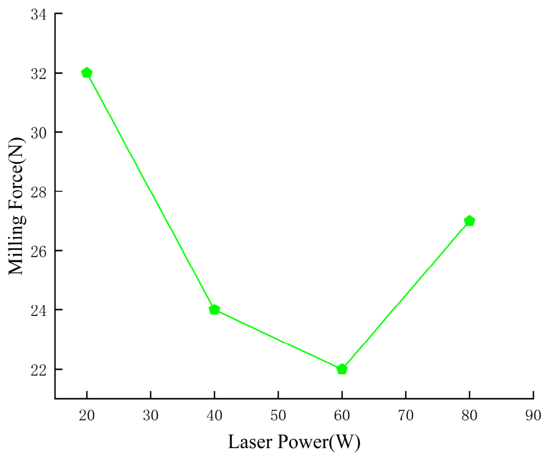
With cutting depth ap fixed at 0.1 mm, milling speed vw maintained at 100 m/min, feed per tooth fz held at 0.04 mm/z, and ultrasonic amplitude A kept constant at 3.0 μm, laser power P was set to 20, 40, 60, and 80 W, respectively. The variation trends of the milling forces during the laser–ultrasonic multi-energy field cutting of the SiCp/Al composites are presented in Figure 6.
It can be observed from Figure 6 that, within a certain range, the milling force decreases with an increase in the laser power, whereas the milling force begins to rise once the laser power exceeds a critical value. At low laser powers, the temperature in the cutting zone remains low, and the material cannot be sufficiently softened, resulting in high cutting resistance. When the laser power is increased to a specific value, the high temperature induces adequate plastic deformation of the workpiece, which greatly reduces the milling force. Further increasing the laser power led to a sharp increase in the temperature of the material surface. This not only aggravated tool wear but also triggered an oxidation hardening effect under high temperature, causing the milling force to increase remarkably again.

3.1.5. Effects of Ultrasonic Amplitude on Milling Forces

As the ultrasonic vibration intensity increases, the periodic relative displacement between the cutting tool and the workpiece increases, thereby enhancing the intermittent nature of the cutting process. Research results indicate that, during milling, an appropriate ultrasonic amplitude can intensify the intermittent cutting effect and reduce the effective friction between the tool and the workpiece, thereby lowering the milling force and improving chip quality. However, an excessively large ultrasonic amplitude may cause fatigue-induced flaking at the cutting edge due to repeated impacts. This phenomenon is particularly pronounced when machining materials containing high-hardness SiC particles.
In this subsection, the variation in milling forces under different ultrasonic amplitudes is analyzed to comprehensively explore the direct and indirect influence mechanisms of the ultrasonic amplitude parameter on the cutting performance. The experimental parameters are listed in Table 8.
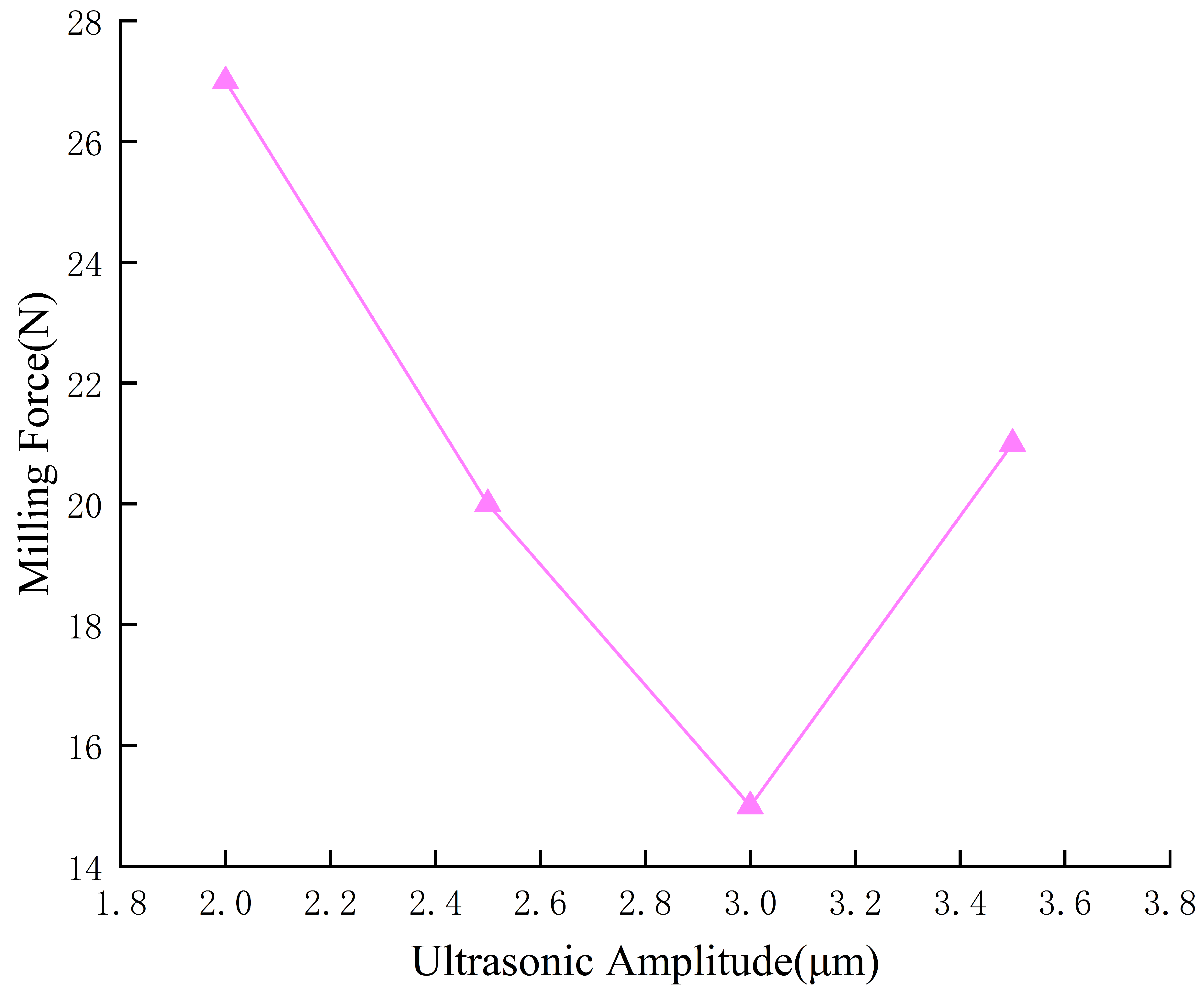
With the milling speed vw fixed at 100 m/min, cutting depth ap maintained at 0.1 mm, feed per tooth fz held at 0.04 mm/z, and laser power P kept constant at 60 W, the ultrasonic amplitude A was set to 2.0 μm, 2.5 μm, 3.0 μm, and 3.5 μm, respectively. The variation trends of the milling forces in the laser–ultrasonic multi-energy field cutting of SiCp/Al composites are shown in Figure 7.
As shown in Figure 7, a low ultrasonic amplitude leads to weak intermittent cutting between the tool and workpiece, and the overall machining process exhibits characteristics close to those of conventional milling. Under such conditions, the friction coefficient is high, and the resistance to chip evacuation is large, resulting in high milling forces. When the ultrasonic amplitude is gradually increased to an appropriate range, the tool can be effectively separated from the workpiece surface in each vibration cycle, forming a stable intermittent cutting process. The friction coefficient was significantly reduced, and thermal management was improved by lowering the temperature in the cutting zone, thereby significantly decreasing the total milling force. If the ultrasonic amplitude exceeds the reasonable range, disordered tool tip trajectories, severe vibration, and additional inertial loads will occur. This increases the probability of undesirable contact between the tool and workpiece, which in turn increases the milling force.

3.2. Influence of Milling Parameters on Tool Wear Quantity

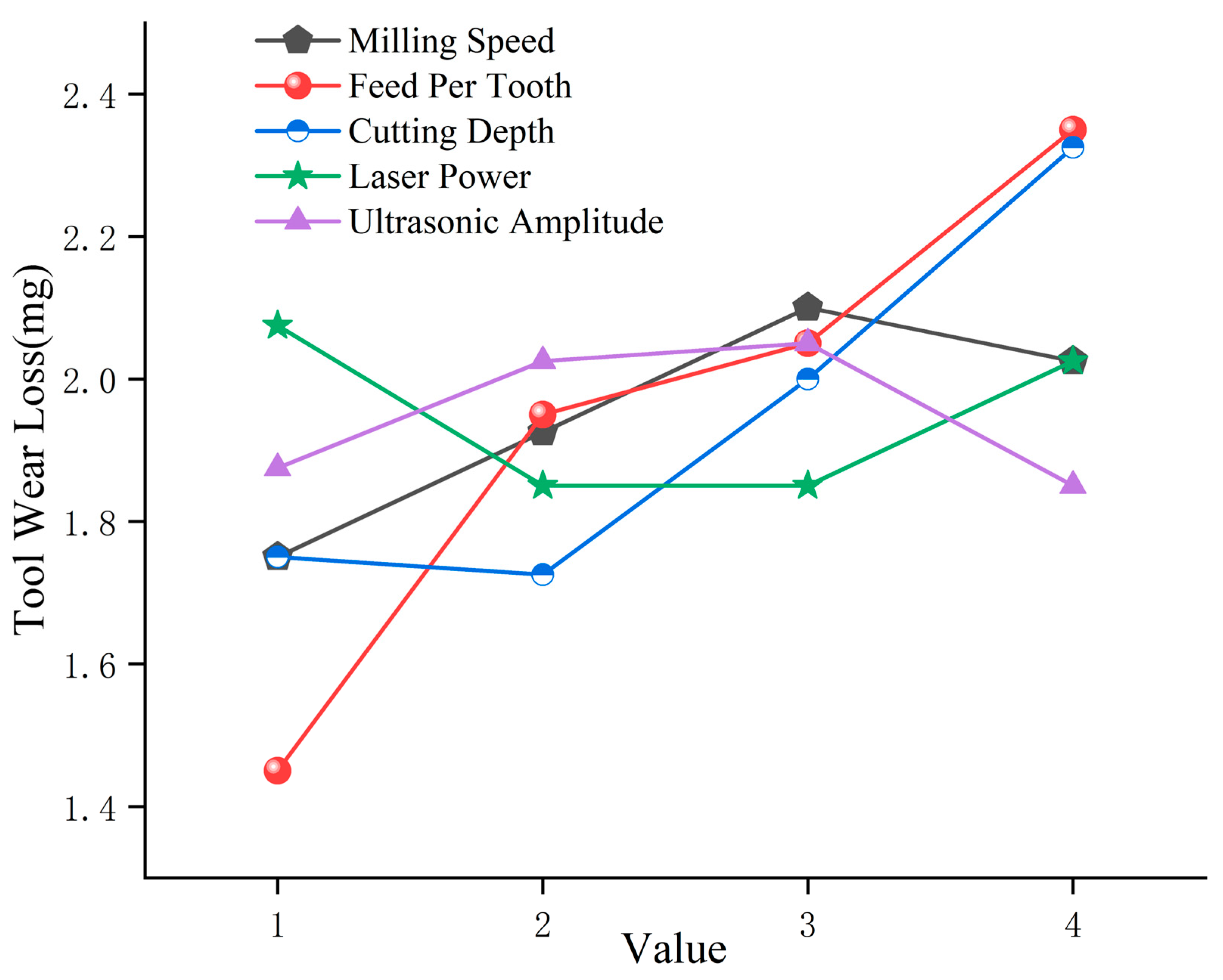
A comparison of the fixed-stroke tool wear data from the orthogonal experiment (Table 3) reveals that Group 7 exhibits the maximum tool wear among all test groups, while Group 1 shows the minimum wear. This indicates that the process parameters of Group 1 can effectively reduce PCD tool loss and extend tool life, whereas the parameters of Group 7 should be avoided in practical machining to prevent rapid tool damage. Figure 8 intuitively illustrates the influence law of each parameter on tool wear: tool wear rises continuously when the milling speed ranges from 50 to 150 m/min, and slightly decreases once the speed exceeds 150 m/min; tool wear increases monotonically with the growth of feed per tooth; increasing the cutting depth aggravates tool wear overall; tool wear gradually declines within the laser power range of 20–60 W, yet rebounds when laser power exceeds 60 W; tool wear rises slightly at ultrasonic amplitudes of 2.0–3.0 μm and drops remarkably after 3.0 μm. According to the range analysis in Table 9 of wear loss, the influence sequence of each parameter on tool wear is as follows: feed per tooth > cutting depth > milling speed > laser power > ultrasonic amplitude. Considering the minimum tool wear as the optimization objective, the optimal parameter combination was determined as follows: milling speed of 50 m/min, feed per tooth of 0.02 mm/z, cutting depth of 0.1 mm, laser power of 60 W, and ultrasonic amplitude of 3.5 μm. Verification experiments conducted with this parameter combination yielded a measured tool wear loss of only 1.0 mg, the lowest value across all test groups. Compared with the other groups, the wear reduction ranged from a minimum of 8.33% to a maximum of 61.54%. The results fully verify the rationality of the optimal parameters obtained from the orthogonal range analysis, and this parameter matching enables low-wear laser–ultrasonic milling of SiCp/Al composites.

3.3. Multiple Linear Regression Model for PCD Tool Wear Loss

During milling, the variable milling parameters exert a critical impact on the tool life. According to international standards, a tool is deemed unusable once it fails to machine workpieces with the required geometric profile and surface quality. In this study, the tool mass was adopted as the evaluation criterion for measuring the tool wear loss, in accordance with [24]. Based on the experimental data in Table 3, the least-squares method was employed to establish the tool life prediction model, as expressed in Equation (2).
S = 4.7586 v w 0.1561 f z 0.3595 a p 0.2171 P 0.0138 A 0.0074
where S denotes tool wear loss in mg, vw is milling speed in m/min, fz represents feed per tooth in mm/z, ap stands for cutting depth in mm, P is laser power in W, and A refers to ultrasonic amplitude in μm. Each exponent characterizes the influence of the corresponding milling parameter on the mass wear of the tool.
Equation (2) was evaluated using the coefficient of determination, yielding R2 = 0.7887. This result indicates that the equation has a reasonable fitting capability and can explain approximately 78.87% of the variation in tool wear loss. An F-test was further conducted using Equation (2). At a significance level of α = 0.05, the F statistic of 7.2877 exceeds the critical F-value of 3.3258, which demonstrates that the overall model is statistically significant. As shown in Equation (2), the feed per tooth has the strongest effect on the flank wear loss of the tool, followed by the cutting depth. The laser power and ultrasonic amplitude were negatively correlated with the flank wear loss, which is consistent with the variation trends of the milling parameters on the flank wear obtained in the previous section.
The measured tool wear data and model prediction results are presented in Table 10. It can be seen that most relative errors between the empirical formula predictions and experimental data are within 10%. This indicates that the empirical equation developed in this study provides reasonably accurate fitting performance.

4. Discussion

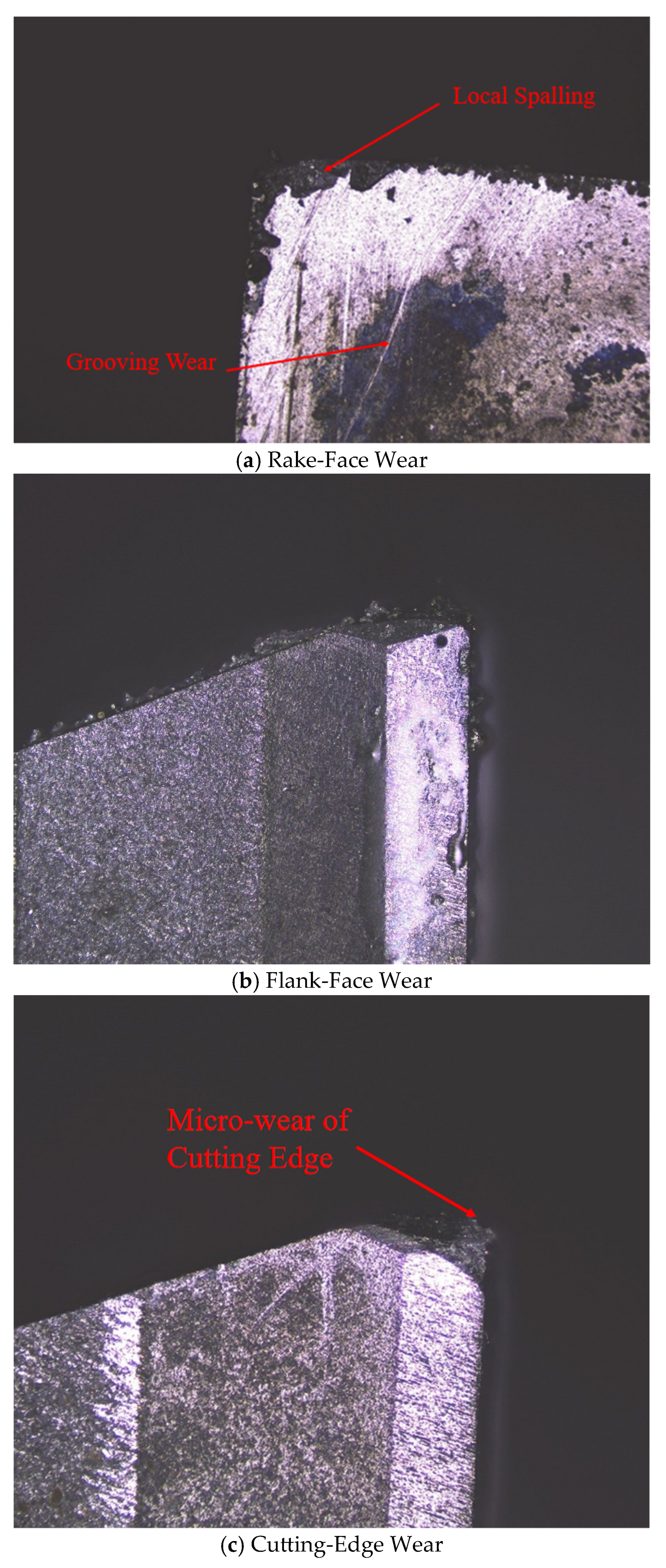
Microscopic observations, as illustrated in Figure 9, revealed that the main wear forms of the PCD tools included scratching and local fatigue spalling on the rake face, mild wear bands on the flank face, and micro-chipping at the cutting edge. Rake-face wear is primarily induced by continuous friction from SiC particle-containing chips and repeated peeling of the adhered aluminum matrix layers. Flank wear arises from friction between the tool and machined surface and exhibits a relatively slight degree, whereas edge micro-chipping is closely associated with periodic impacts of hard SiC particles. Laser thermal softening can reduce the resistance to particle removal, and ultrasonic vibration can shorten the continuous contact duration between the tool and workpiece. Nevertheless, excessive heat input or ultrasonic amplitude may trigger adhesive wear, thermal damage, and impact wear. Accordingly, selecting a rational process window is more significant than simply increasing the parameters of a single energy field.
In terms of multi-energy field parameters, the laser power and ultrasonic amplitude exert bidirectional regulatory effects on PCD tool wear. Appropriate laser power reduces material removal resistance via thermal softening and alleviates the mechanical loads on the tool, thereby mitigating abrasive and impact wear. Nevertheless, excessively high power leads to overheating in the cutting zone, accelerating the graphitization and thermal wear of PCD tools and ultimately aggravating the total tool loss. Ultrasonic vibration also possesses an optimal parameter window; an excessively large amplitude drastically elevates the impact loads on the cutting edge and increases the risk of edge micro-chipping [25]. From the perspective of technological factors, the milling speed, feed per tooth, and cutting depth alter the cutting loads and cutting temperatures to regulate the progression of tool wear. Within the experimental parameter range, the tool wear increased approximately linearly with increasing feed per tooth, which stems from the thicker uncut chip thickness that intensifies the impact loads induced by the SiC particles. Regarding workpiece material factors, the volume fraction, particle size, and distribution of SiC particles are the dominant determinants of the tool wear rate. Higher volume fractions imply that more SiC particles interact with the tool per unit time, resulting in more severe wear. Larger SiC particles generated more severe single-impact damage and readily triggered cutting-edge micro-chipping.
Rake-face wear arises from the combined effects of abrasive grooving and adhesive wear. The chips contain abundant hard SiC particles that slide over the rake face at a high velocity, producing repeated micro-cutting and scratching to form grooved wear traces aligned with the chip flow directions. Meanwhile, the aluminum matrix material easily adheres to the rake face under high temperature and pressure to form a built-up edge (BUE). The periodic formation and detachment of the built-up edge strip away the partial tool material and induce spalling-type wear.
Flank wear was dominated by abrasive wear. Persistent scratching by SiC particles gradually removed the tool substrate material and formed a wear land with a definite width. As wear progresses, the flank angle decreases, enlarging the frictional contact area between the tool and machined surface and elevating the cutting temperature, which further accelerates wear evolution. Flank wear loss is generally adopted as the primary evaluation indicator of tool life.
Cutting-edge wear represents the most critical wear mode affecting machining quality, mainly manifested as edge blunting and micro-chipping. Owing to the frequent high-frequency impacts from SiC particles, PCD cutting edges develop varying degrees of micro-chipping and tiny pits at the early machining stage. As the cutting distance increases, the edge radius gradually expands to dull the cutting edge, which increases the cutting forces and degrades the surface integrity.

5. Conclusions

To address the severe tool wear problem during the conventional machining of 70 vol.% SiCp/Al composites, this paper proposes a collaborative milling process coupled with pulsed laser and ultrasonic vibration. Orthogonal tests, single-factor experiments, range analysis, multiple linear regression modeling, and microscopic morphology observations were conducted to systematically reveal the coupling mechanism of laser–ultrasonic multi-energy fields, the evolution laws of milling forces and PCD tool wear, and the primary failure modes of cutting tools. The main conclusions are as follows:
(1) Milling forces exhibited distinct variation trends under different process parameters. The milling force first decreased and then increased sharply with an increase in the milling speed. When the feed per tooth and cutting depth increased, the milling force increased monotonically. Within the laser power range of 20–60 W, the milling force decreased gradually as the power increased; once the power exceeded 60 W, the high-temperature oxidation hardening effect caused the milling force to rebound. A reasonable ultrasonic amplitude of 3.0 μm can form stable intermittent cutting and effectively reduce friction and cutting loads, whereas excessively large or small amplitudes lead to increased milling forces.
(2) A multiple linear regression prediction model for PCD tool wear was established based on orthogonal experimental data, with a coefficient of determination R2 = 0.7887. The F-test at a significance level of 0.05 verified that the overall model was statistically significant. The feed per tooth was the major factor that aggravated flank wear, whereas laser power and ultrasonic amplitude were negatively correlated with flank wear. The relative error between the predicted wear values and measured wear loss was mostly controlled within 10%, which verified that the empirical formula has a reliable prediction accuracy for the PCD tool wear loss.
(3) Microscopic observation of worn PCD tools identified four typical tool failure modes: grooving wear and fatigue spalling on the rake face, abrasive wear bands on the flank face, and micro-chipping of cutting edges. The pulsed laser reduced the shear resistance of the SiC particles through thermal softening, and the ultrasonic vibration shortened the continuous contact time between the tool and workpiece. The synergistic effect of the dual energy fields can simultaneously restrain abrasive wear, adhesive wear, and edge chipping. Nevertheless, laser power or ultrasonic amplitude beyond a reasonable parameter window will induce thermal damage and impact the fatigue wear of tools.
(4) Both the laser power and ultrasonic amplitude have bidirectional regulation effects on tool wear. Moderate energy input softens the Al matrix and lowers the impact load of SiC particles. Excessively high laser energy triggers thermal graphitization of PCD tools and oxidation hardening of the workpiece, and an overly large ultrasonic amplitude aggravates the cyclic impact damage on the cutting edges. Matching a suitable parameter window for the dual energy fields is the core approach to realize low-wear milling of high-volume-fraction SiCp/Al composites and to extend the service life of PCD tools.

Author Contributions

Conceptualization, L.Y., K.Z. and J.Q.; methodology, L.Y., K.Z. and J.Q.; validation, L.Y., K.Z., E.L., Q.L. and S.Y.; data curation, J.Q., E.L., S.Y. and G.L.; writing—original draft preparation, L.Y., K.Z., J.Q. and E.L.; writing—review and editing, E.L. and S.Y.; supervision, L.Y., K.Z., Q.L., S.Y. and G.L.; project administration, Q.L. and G.L.; funding acquisition, G.L. All authors have read and agreed to the published version of the manuscript.

Funding

This research was funded by the Henan Province Science and Technology Research and Development Joint Fund (grant No. 202324119, 20250104, 252103810171); Henan Key Research and Development and Promotion Special Project (Science and Technology Tackling) (grant No. 262102231017, 262102231018); Guizhou Institute of Technology Doctoral Startup Fund (grant No. 2023GCC033); and China Iron and Steel Education Society Fund Project (Grant No. SYJX2024033).

Institutional Review Board Statement

Not applicable.

Informed Consent Statement

Not applicable.

Data Availability Statement

The original contributions presented in this study are included in the article. Further inquiries can be directed to the corresponding author.

Acknowledgments

During the preparation of this manuscript, the authors used PaperPal (v2026.4.30) for language editing assistance and Grammarly (v14.1313.0) for linguistic polishing. The authors have reviewed and edited the output and take full responsibility for the content of this publication.

Conflicts of Interest

The authors declare no conflicts of interest.

References

  1. Wang, H.X.; Yang, J.; Liu, Z.S.; Zhai, W.J. Experimental research on the tool wear during precision milling process of SiCp/Al composite materials. Mater. Sci. Technol. 2012, 20, 12–15. [Google Scholar]
  2. Hao, Z.P.; Xu, Y.S.; Fan, Y.H.; Lin, J.Q. Overview of research on machining mechanism of aluminum-based silicon carbide composites (SiCp/Al). Int. J. Adv. Manuf. Tech. 2024, 133, 3133–3149. [Google Scholar] [CrossRef] [Scilit]
  3. Zhou, Y.; Zhang, D.Y.; Wang, W.D.; Li, L.S. Current Situation and Aerospace Applications Analysis Based on SiC Particle Reinforced Aluminum Matrix Composites Manufactured by Selective Laser Melting. Aeronaut. Manuf. Technol. 2018, 61, 68–73. [Google Scholar] [CrossRef]
  4. Mao, P.C.; Yan, X.Z.; Wu, S.; Chu, J.H.; Yang, B.Y. Precision Milling Experiment Study of High-Volume Fraction SiCp/Al Composites. Aerosp. Shanghai (Chin. Engl.) 2024, 41, 168–174. [Google Scholar] [CrossRef]
  5. Cui, Y.; Li, L.F.; Li, J.L.; Ren, J.Y. High volume fraction SiC/Al composites for space-based optomechanical structures. Opt. Precis. Eng. 2007, 15, 1175–1180. [Google Scholar]
  6. Zhao, C.Y.; Han, J.S.; Wang, Y.; Zhao, B.; Tang, J.Y. Research Progress on High Efficiency and Low Damage Processing Technology of SiCp/Al Composite. Tool Eng. 2025, 59, 1–19. [Google Scholar] [CrossRef]
  7. Zha, H.T.; Feng, P.F.; Zhang, J.F.; Yu, D.W.; Wu, Z.J. Wear characteristics of cutting tools in ultrasonic vibration assisted scratching high volume fraction SiC particle reinforced aluminum matrix composites. J. Jilin Univ. (Eng. Technol. Ed.) 2019, 49, 458–465. [Google Scholar] [CrossRef]
  8. Huang, Y.H.; Zhou, Y.Q.; Li, J.M.; Zhu, F.L. Materials removal mechanism and multi modes feature for silicon carbide during scratching. Int. J. Mech. Sci. 2022, 235, 107719. [Google Scholar] [CrossRef] [Scilit]
  9. Lin, J.Q.; Jia, R.; Zhou, Y.; Gu, Y. PCD tool wear in cutting SiCp/6005Al composites. Diam. Abras. Eng. 2023, 43, 322–331. [Google Scholar] [CrossRef]
  10. Wang, Y.J.; Zhan, Y.Y.; Li, Z.X. Research progress on the wear problem of polycrystalline diamond cutting tools. Superhard Mater. Eng. 2025, 37, 43–51. [Google Scholar]
  11. Grigoriev, S.N.; Volosova, M.A.; Okunkova, A.A. Investigation of Surface Layer Condition of SiAlON Ceramic Inserts and Its Influence on Tool Durability When Turning Nickel-Based Superalloy. Technologies 2023, 11, 11. [Google Scholar] [CrossRef] [Scilit]
  12. Zhang, H.P.; Wang, B.W.; Qu, L.Q.; Wang, X.R. Optimization of Tool Wear and Cutting Parameters in SCCO2-MQL Ultrasonic Vibration Milling of SiCp/Al Composites. Machines 2024, 12, 646. [Google Scholar] [CrossRef] [Scilit]
  13. Yu, W.W.; Chen, J.; Ming, W.W.; An, Q.L.; Chen, M. Experimental and FEM study of cutting mechanism and damage behavior of ceramic particles in orthogonal cutting SiCp/Al composites. Ceram. Int. 2021, 47, 7183–7194. [Google Scholar] [CrossRef] [Scilit]
  14. Zhou, Y.; Gu, Y.; Lin, J.Q.; Zhao, H.B.; Liu, S.Y.; Xu, Z.S.; Yu, H.; Fu, X.B. Finite element analysis and experimental study on the cutting mechanism of SiCp/Al composites by ultrasonic vibration-assisted cutting. Ceram. Int. 2022, 48, 35406–35421. [Google Scholar] [CrossRef] [Scilit]
  15. Ali, R.L.; Li, J.G. Modeling and optimization of cutting forces and effect of turning parameters on SiCp/Al 45% vs SiCp/Al 50% metal matrix composites: A comparative study. SN Appl. Sci. 2021, 3, 706. [Google Scholar] [CrossRef] [Scilit]
  16. Sun, W.C.; Liu, P.Z.; Cao, J.W.; Wang, W.; Peng, C.; Chen, H.W.; Du, H.H. Laser assisted machining of hard and brittle materials in aerospace fields: A review. Chin. J. Aeronaut. 2026, 104168. [Google Scholar] [CrossRef] [Scilit]
  17. Eshelby, J.D.; Frank, F.C.; Nabarro, F.R.N. XLI. The equilibrium of linear arrays of dislocations. Lond. Edinb. Dublin Philos. Mag. J. Sci. 1951, 42, 351–364. [Google Scholar] [CrossRef] [Scilit]
  18. Zheng, W.; Zhou, M.; Zhou, L. Influence of process parameters on surface topography in ultrasonic vibration-assisted end grinding of SiCp/Al composites. Int. J. Adv. Manuf. Technol. 2017, 91, 2347–2358. [Google Scholar] [CrossRef] [Scilit]
  19. Ji, C.H.; Hu, S.G.; Xu, W.H.; Wang, X.M.; Xu, L.D.; Xin, H.Y.; Dong, L.; Zhang, X.T.; Zhang, Y.B.; Ma, X.; et al. Kinematic analysis of ultrasonic vibration-assisted milling SiCp/Al composites and surface quantity assessment. Int. J. Adv. Manuf. Technol. 2025, 141, 351–367. [Google Scholar] [CrossRef] [Scilit]
  20. Fan, Y.H.; Yang, C.H.; Hao, Z.P. Analysis of interfacial failure and particle damage of SiCp/Al with ultrasonic vibration-assisted cutting. Eng. Fail. Anal. 2025, 169, 109225. [Google Scholar] [CrossRef] [Scilit]
  21. Zhao, G.L.; Xin, L.J.; Li, L.; Zhang, Y.; He, N.; Hansen, H.N. Cutting force model and damage formation mechanism in milling of 70wt% Si/Al composite. Chin. J. Aeronaut. 2023, 36, 114–128. [Google Scholar] [CrossRef] [Scilit]
  22. Fan, Y.H.; Xu, Y.S.; Hao, Z.P.; Lin, J.Q. Dynamic behavior description and three-dimensional cutting simulation of SiCp/Al composites with high volume fraction. J. Manuf. Process. 2022, 77, 174–189. [Google Scholar] [CrossRef] [Scilit]
  23. Sun, S.J.; Chen, Z.Y.; Liu, D.L.; Liu, S.Y. Simulation and Experimental Study on Milling of SiCp/Al Composites. Model. Simul. 2024, 13, 82–92. [Google Scholar] [CrossRef]
  24. Yan, H.P.; Wu, Y.H. Effects of Cutting Parameters for Marble Milling on Wear of PCD Cutters. Surf. Technol. 2017, 46, 245–249. [Google Scholar] [CrossRef]
  25. Ding, Z.W.; Chen, Q.H.; Shi, Y.G.; Song, P. Wear Mechanisms of PCD Tools in High-Speed Milling of High Volume Fraction of SiCp/Al Composites. Tool Eng. 2016, 50, 30–34. [Google Scholar] [CrossRef]
Figure 1. Experimental platform for laser–ultrasonic synergistic milling of 70 vol.% SiCp/Al composites.
Jmmp 10 00305 g001
Figure 2. EasyZoom 5 ultra-depth-of-field microscopes.
Jmmp 10 00305 g002
Figure 3. Effects of milling speed on the milling forces.
Jmmp 10 00305 g003
Figure 4. Effects of feed rate on milling forces.
Jmmp 10 00305 g004
Figure 5. Effects of cutting depth on milling forces.
Jmmp 10 00305 g005
Figure 6. Effects of laser power on the milling forces.
Jmmp 10 00305 g006
Figure 7. Effect of ultrasonic amplitude on milling forces.
Jmmp 10 00305 g007
Figure 8. Effects of milling parameters on tool wear loss.
Jmmp 10 00305 g008
Figure 9. PCD tool wear.
Jmmp 10 00305 g009
Table 1. Physical properties of 70 vol.% SiCp/Al composite.
Density [g/cm3]Poisson’s RatioShear Modulus [GPa]Flexural Strength [MPa]
3.020.2899.6395
Table 2. Experimental parameters.
LevelsMilling Speed
vw (m/min)
Feed Per Tooth
fz (mm/z)
Cutting Depth
ap (mm)
Laser Power P (W)Ultrasonic Amplitude
A (μm)
1500.020.05202.0
21000.040.1402.5
31500.060.15603.0
42000.080.2803.5
Table 3. Milling experimental results.
NumberMilling Speed
vw (m/min)
Feed Per Tooth
fz (mm/z)
Cutting Depth
ap (mm)
Laser Power P (W)Ultrasonic Amplitude
A (μm)
Fx(N)Fy(N)Fz(N)Tool Wear Loss (mg)
1500.020.05202.031.62313.10628.7321.1
2500.040.1402.528.89420.84641.8671.5
3500.060.15603.037.99822.12854.0051.9
4500.080.2803.560.35919.75644.5372.5
51000.020.1603.521.98515.69845.3161.0
61000.040.05803.036.03818.66324.1111.9
71000.060.2202.555.21418.41346.3122.6
81000.080.15402.040.21125.74454.2122.2
91500.020.15802.529.03516.0331.5951.8
101500.040.2602.044.01421.6838.7622.3
111500.060.05403.521.32820.93524.0731.8
121500.080.1203.034.54122.97844.9112.5
132000.020.2403.032.64814.47134.0661.9
142000.040.15203.529.40720.00847.1082.1
152000.060.1802.036.98115.07331.6311.9
162000.080.05602.525.95521.16237.4442.2
Table 4. Milling test parameters at different milling speeds.
NumberMilling Speed
vw (m/min)
Feed Per Tooth
fz (mm/z)
Cutting Depth
ap (mm)
Laser Power P (W)Ultrasonic Amplitude
A (μm)
1500.040.1603.0
21000.040.1603.0
31500.040.1603.0
42000.040.1603.0
Table 5. Feed per tooth experimental parameters.
NumberMilling Speed
vw (m/min)
Feed Per Tooth
fz (mm/z)
Cutting Depth
ap (mm)
Laser Power P (W)Ultrasonic Amplitude
A (μm)
11000.020.1603.0
21000.040.1603.0
31000.060.1603.0
41000.080.1603.0
Table 6. Cutting depth experimental parameters.
NumberMilling Speed
vw (m/min)
Feed Per Tooth
fz (mm/z)
Cutting Depth
ap (mm)
Laser Power P (W)Ultrasonic Amplitude
A (μm)
11000.040.05603.0
21000.040.1603.0
31000.040.15603.0
41000.040.2603.0
Table 7. Laser power experimental parameters.
NumberMilling Speed
vw (m/min)
Feed Per Tooth
fz (mm/z)
Cutting Depth
ap (mm)
Laser Power P (W)Ultrasonic Amplitude
A (μm)
11000.040.1203.0
21000.040.1403.0
31000.040.1603.0
41000.040.1803.0
Table 8. Ultrasonic amplitude experimental parameters.
NumberMilling Speed
vw (m/min)
Feed Per Tooth
fz (mm/z)
Cutting Depth
ap (mm)
Laser Power P (W)Ultrasonic Amplitude
A (μm)
11000.040.1602.0
21000.040.1602.5
31000.040.1603.0
41000.040.1603.5
Table 9. Range analysis of tool wear loss.
ValueMilling Speed
vw (m/min)
Feed Per Tooth
fz (mm/z)
Cutting Depth
ap (mm)
Laser Power P (W)Ultrasonic Amplitude
A (μm)
11.751.451.752.0751.875
21.9251.951.7251.852.025
32.1002.052.01.852.05
42.0252.352.3252.0251.85
Range value0.350,90.60.2250.2
Table 10. Comparison between measured and predicted wear values.
SampleMeasured Wear ValuePredicted Wear ValueRelative Error
11.1000001.0698692.74%
21.5000001.577655−5.18%
31.9000001.979332−4.18%
42.5000002.3245087.02%
51.0000001.359221−35.92%
61.9000001.49589421.27%
72.6000002.3868798.20%
82.2000002.466945−12.13%
91.8000001.57891712.28%
102.3000002.1683715.72%
111.8000001.859359−3.30%
122.5000002.4226503.09%
131.9000001.7724566.71%
142.1000002.154417−2.59%
151.9000002.248267−18.33%
162.2000002.1498892.28%
Disclaimer/Publisher’s Note: The statements, opinions and data contained in all publications are solely those of the individual author(s) and contributor(s) and not of MDPI and/or the editor(s). MDPI and/or the editor(s) disclaim responsibility for any injury to people or property resulting from any ideas, methods, instructions or products referred to in the content.