Article

Drilling Performance Evaluation and Mechanism Analysis of Diamond-Coated Drills in Ice-Supported CFRP Machining


1
College of Electromechanical and Automotive Engineering, Yantai University, Yantai 264000, China
2
College of Mechanical Engineering, Dalian University of Technology, Dalian 116081, China
*
Author to whom correspondence should be addressed.
J. Manuf. Mater. Process. 2026, 10(8), 304; https://doi.org/10.3390/jmmp10080304
Submission received: 14 July 2026 / Revised: 13 August 2026 / Accepted: 16 August 2026 / Published: 18 August 2026

Abstract

Diamond-coated tools are suitable for CFRP machining because of their high hardness, sharp cutting edge, and good wear resistance. However, the anisotropic and heterogeneous nature of CFRP makes drilling-induced defects, such as burrs, tearing, fiber pull-out, and delamination, difficult to avoid, especially at the hole exit. In this study, an ice-supported drilling method was proposed for CFRP hole machining using diamond-coated drills. An ice layer was formed beneath the CFRP laminate to provide simultaneous low-temperature cooling and mechanical support during drilling. Comparative drilling experiments were conducted at spindle speeds of 400, 1200, and 2000 r/min. The results showed that the ice-supported drilling method markedly improved the hole surface quality and inner-wall integrity of CFRP laminates. Compared with conventional dry drilling, the drilling temperature was reduced by 22.03%, 10.70%, and 11.45% at 400, 1200, and 2000 r/min, respectively, while the hole-exit delamination factor decreased by 41.68%, 27.45%, and 57.04%, respectively. Moreover, after the same number of drilled holes, the diamond-coated drill used under ice-supported conditions exhibited less severe surface wear and cutting-edge blunting than that used under conventional dry conditions. The observed improvements were interpreted as being associated with the combined thermal-regulation and temporary mechanical-backing effects of the ice-supported condition.

1. Introduction

Carbon-fiber-reinforced polymer (CFRP) composites have been widely used in the automotive and aerospace industries owing to their low density, high specific strength, high specific stiffness, and excellent corrosion resistance [1,2]. Although CFRP components can be manufactured to near-net shape, secondary machining operations are generally required to satisfy dimensional accuracy, geometrical tolerance, and assembly requirements. Among these operations, drilling is particularly important because holes are required for the mechanical assembly of CFRP structural components. However, the high abrasiveness of carbon fibers can accelerate tool wear, which subsequently affects machining quality [3]. Therefore, wear-resistant carbide and coated drills, including diamond-coated drills, have been investigated for CFRP machining to improve tool durability and hole quality [4]. During CFRP drilling, the high hardness and abrasive nature of carbon fibers often lead to a significant increase in drilling forces, which can induce severe machining defects such as burr formation, tearing, delamination, and fiber pull-out [5,6]. These defects originate from the heterogeneous and laminated structure of CFRP, which consists of carbon fibers embedded within a polymer matrix. The occurrence of such damage not only deteriorates hole quality but also poses substantial challenges to the reliable assembly and long-term service performance of CFRP components, particularly in applications demanding high structural integrity and operational safety.
Drilling-induced damage in CFRP laminates is mainly concentrated in the hole-entrance, hole-exit, and hole-wall regions. Burr formation is the predominant defect at the hole entrance, which is primarily caused by the peeling action of the drill corner on the laminate surface [7]. Owing to the relatively low interlaminar bonding strength of CFRP laminates, irreversible delamination damage can occur when the axial thrust force exceeds the interlaminar strength, thereby compromising the structural integrity of the workpiece [8,9]. Furthermore, severe friction between the drill and the high-hardness carbon fibers generates a substantial amount of cutting heat. Due to the semi-enclosed nature of the drilling process and the poor thermal conductivity of CFRP in the thickness direction, heat accumulation tends to occur inside the hole as the drilling depth increases [10], which may induce additional thermal damage and further deteriorate machining quality [11,12]. These drilling-induced defects can significantly shorten the fatigue life of CFRP components and reduce their structural stability, tensile strength, and load-bearing capacity. Therefore, effective CFRP drilling strategies should simultaneously address mechanical damage caused by drilling loads and thermal damage induced by cutting heat.
To address the defects commonly encountered during CFRP drilling, existing studies have mainly focused on improving machining conditions from the perspectives of mechanical loading and thermal regulation. Regarding the mechanical aspect, drilling quality is strongly influenced by the thrust force generated during machining, which is mainly determined by the tool material, drill geometry, and cutting parameters. Based on linear elastic fracture mechanics (LEFM), Ho-Cheng and Dharan [13] established an analytical model for drilling-induced delamination that correlated delamination initiation with the thrust force and the mechanical properties of the composite laminate. They demonstrated that reducing the thrust force near the hole exit is an effective approach for suppressing delamination propagation. Hocheng and Tsao [14] systematically reviewed critical-thrust-force models for delamination-free drilling using special drill geometries, as well as several non-conventional machining processes for composite laminates. Similarly, König et al. [15] reported that the extent of drilling-induced delamination is closely associated with the thrust force and proposed a critical-thrust-force threshold, below which delamination does not occur. Tsao and Hocheng [16] investigated the influence of backing support on drilling-induced delamination and found that additional support beneath composite laminates increased the critical thrust force required for delamination initiation, thereby reducing the susceptibility of CFRP laminates to drilling-induced damage. Accordingly, support-assisted drilling methods have attracted increasing attention. In practical applications, backing structures are commonly installed beneath composite workpieces to prevent deformation and suppress exit delamination. However, conventional backing supports mainly act on the hole-exit region, and their effectiveness in addressing other machining defects, such as burr formation and thermal damage, remains limited. In addition to mechanical support, previous studies have also explored the regulation of the thermal environment during CFRP machining. Existing approaches have primarily focused on three technical strategies, including optimization of drill geometry, development of advanced protective coatings, and optimization of machining parameters [17]. Although these approaches have demonstrated varying degrees of effectiveness in suppressing drilling-induced damage, several limitations remain. Tool geometry optimization and coating development generally require lengthy research and development cycles, as well as considerable manufacturing and validation costs, whereas optimization of machining parameters can only alleviate rather than fundamentally eliminate drilling-induced defects [18,19]. Therefore, cryogenic and low-temperature-assisted machining technologies have attracted considerable attention as promising approaches for mitigating thermally induced damage during composite machining [20,21]. Koklu and Morkavuk [22] investigated the drilling behavior of CFRP following cryogenic pretreatment using liquid nitrogen and reported significant reductions in tool wear and hole-wall surface roughness. Liu et al. [23] compared the drilling quality of CFRP/titanium stacks under room-temperature, dry-ice cooling, and liquid-nitrogen cooling conditions, demonstrating that low-temperature environments effectively alleviated exit burr formation and thermal damage. Zou et al. [24] studied the machining performance of CFRP during cryogenic milling and found that cryogenic machining significantly reduced cutting temperature and improved surface quality due to the enhanced material stiffness and interfacial bonding strength under low-temperature conditions. Similarly, Dalle Mura and Dini [25] reported that cryogenic drilling reduced delamination damage and promoted brittle fracture behavior accompanied by compact fiber bundles, resulting in higher-quality holes with smoother inner-wall surfaces.
Besides conventional cryogenic machining, ice has also been explored as a temporary backing medium for composite drilling. Sahami Poor Dehghan and Heidary [26] compared the drilling performance of filament-wound GFRP composite pipes under unsupported and ice-supported conditions and reported that ice used as a temporary backing medium reduced the drilling-induced delamination area. Despite the demonstrated advantages of backing support and cryogenic machining, these approaches have generally been investigated independently. Backing supports primarily enhance the mechanical constraint of the exit region, whereas cryogenic machining mainly addresses thermal damage and tool wear. To date, studies integrating both mechanical support and low-temperature assistance for CFRP drilling remain scarce. Therefore, the development of a machining strategy capable of simultaneously providing exit support and cooling effects represents a promising direction for improving drilling quality and suppressing drilling-induced damage in CFRP laminates.
To address these issues, an ice-supported drilling strategy is proposed in this study. By freezing an ice layer beneath the CFRP laminate, the proposed method simultaneously reduces heat accumulation during drilling and provides additional mechanical support to the laminate. A series of comparative drilling experiments, theoretical analyses, drilling temperature measurements, and microscopic observations of machined surfaces were conducted to evaluate the performance of the proposed ice–CFRP combined machining approach and to elucidate its underlying mechanisms. The effects of ice support on drilling temperature, hole quality, delamination suppression, and tool wear behavior were systematically investigated. The findings of this study demonstrate the feasibility of ice-supported drilling as an alternative strategy for improving CFRP hole-making quality. Although rigid backing plates and liquid-nitrogen-assisted drilling may achieve comparable or even superior machining performance under optimized conditions, the proposed method provides an alternative strategy by integrating temporary mechanical support and thermal regulation using ordinary water, a reusable mold, and conventional freezing equipment. This simple auxiliary strategy reduces the dependence on additional supporting components and complex auxiliary systems. Moreover, the use of water as the supporting and cooling medium and the natural removal of the ice layer after machining indicate potential environmental benefits by minimizing auxiliary material consumption and waste generation.

2. Materials and Methods

2.1. Materials and Experimental Procedures

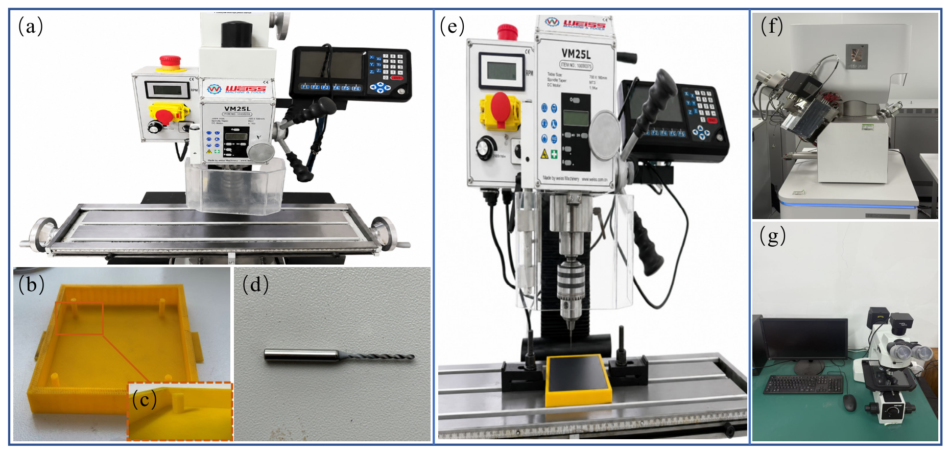
The workpiece material employed in this study was a woven CFRP laminate consisting of T800 carbon fibers and a thermosetting epoxy resin matrix. The carbon fiber and epoxy resin volume fractions were 65% and 35%, respectively. The prepreg was fabricated using a 0°/90° lay-up sequence, and the laminate dimensions were 100 mm × 100 mm × 1 mm. The CFRP laminates were provided by Dongguan Huangbao Hardware & Plastic Products Co., Ltd (Dongguan, China). Drilling experiments were performed using a chemical vapor deposition (CVD) diamond-coated drill with a diameter of 1.6 mm and a point angle of 118°. All drilling tests were conducted on a VM25L drilling–milling machine with a maximum spindle speed of 2250 r/min. To achieve a flat and uniform bonding interface between the ice layer and the CFRP laminate, a customized mold was designed and fabricated using three-dimensional (3D) printing technology. The fixture was equipped with rectangular side plates and rigidly mounted on the machine table through metallic clamps, ensuring sufficient stability throughout the drilling process. The machined hole quality, hole-wall morphology, and delamination characteristics were characterized using optical microscopy and scanning electron microscopy (SEM). Tool wear behavior and coating degradation were further examined by SEM observations. The experimental apparatus and characterization instruments employed in this study are presented in Figure 1.
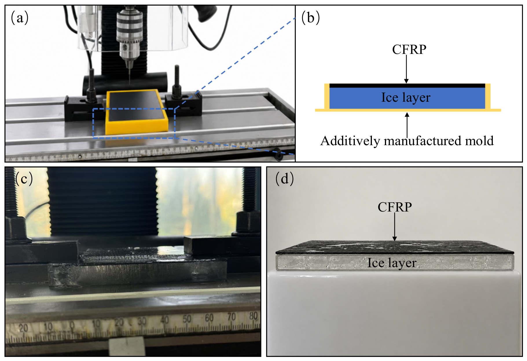
To evaluate the effectiveness of the proposed ice-supported drilling method for CFRP machining, comparative drilling experiments were conducted between conventional dry drilling and ice-supported drilling. For both drilling methods, spindle speeds of 400, 1200, and 2000 r/min were employed, while the feed rate was maintained at 0.001 mm/rev. Under each machining condition, 20 holes were drilled consecutively to evaluate the machining performance during a fixed drilling sequence. For the ice-supported drilling method, a customized mold with dimensions of 105 mm × 105 mm × 15 mm (length × width × height) was fabricated. Four cylindrical supports with a height of 14 mm were positioned around the inner perimeter of the mold to support the CFRP laminate. Water was then introduced beneath the workpiece to establish complete contact between the CFRP laminate and the liquid layer. Subsequently, the entire assembly was frozen at −10 °C to solidify the water, thereby forming an ice layer bonded to the underside of the laminate. After freezing, the contact condition between the CFRP laminate and the ice layer was checked before drilling. If obvious gaps, local separation, uneven contact, or insufficient bonding were identified, the corresponding ice-supported configuration was not used for drilling. The ice support was remanufactured and the freezing procedure was repeated until continuous and stable macroscopic contact was obtained. Therefore, drilling tests were performed only under acceptable CFRP–ice contact conditions. During drilling, the ice layer simultaneously served as a cooling medium and a temporary backing support. The cooling effect reduced heat accumulation within the drilling zone, whereas the supporting effect enhanced the stiffness of the laminate near the hole exit, thereby mitigating drilling-induced damage. A schematic illustration of the bonding configuration between the ice layer and the CFRP laminate is presented in Figure 2.

2.2. Evaluation Methods for Machining Defects

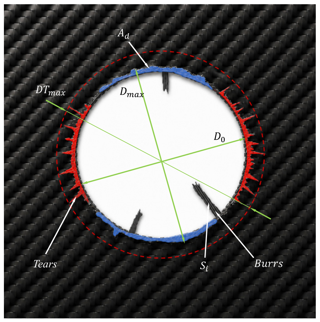
During the drilling of CFRP composites, typical machining-induced defects, such as burr formation, tearing, and delamination, are frequently generated. A schematic illustration of these defects is shown in Figure 3. To quantitatively evaluate the influence of different drilling strategies on machining-induced damage, defect factors were defined and calculated for burr formation, tearing, and delamination. The burr factor Fb, tearing factor Ft, and delamination factor Fda were determined according to Equations (1)–(3). These parameters provide a quantitative assessment of drilling quality and enable comparisons of machining performance under different processing conditions [8].
F b = A b A 0 = ∑ 1 n A b i π D 0 2 4 = 4 ∑ 1 n A b i π D 0 2
F t = D T m a x D 0
F da = α D max D 0 + β A d A 0
where Abi represents the area of the i-th burr, D0 is the nominal diameter of the CFRP hole, and A0 denotes the theoretical hole area of CFRP. DTmax represents the maximum nominal diameter measured in the tearing region, while Dmax denotes the maximum diameter associated with the delaminated region. Ad is the actual area of the delaminated region, and α and β are weighting coefficients.

3. Results and Discussion

3.1. Analysis of Hole-Wall Quality

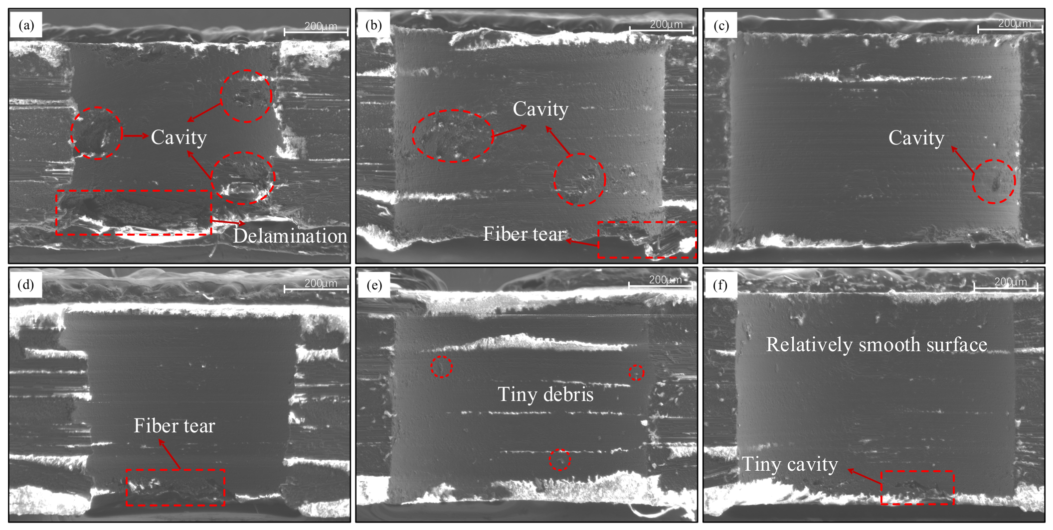
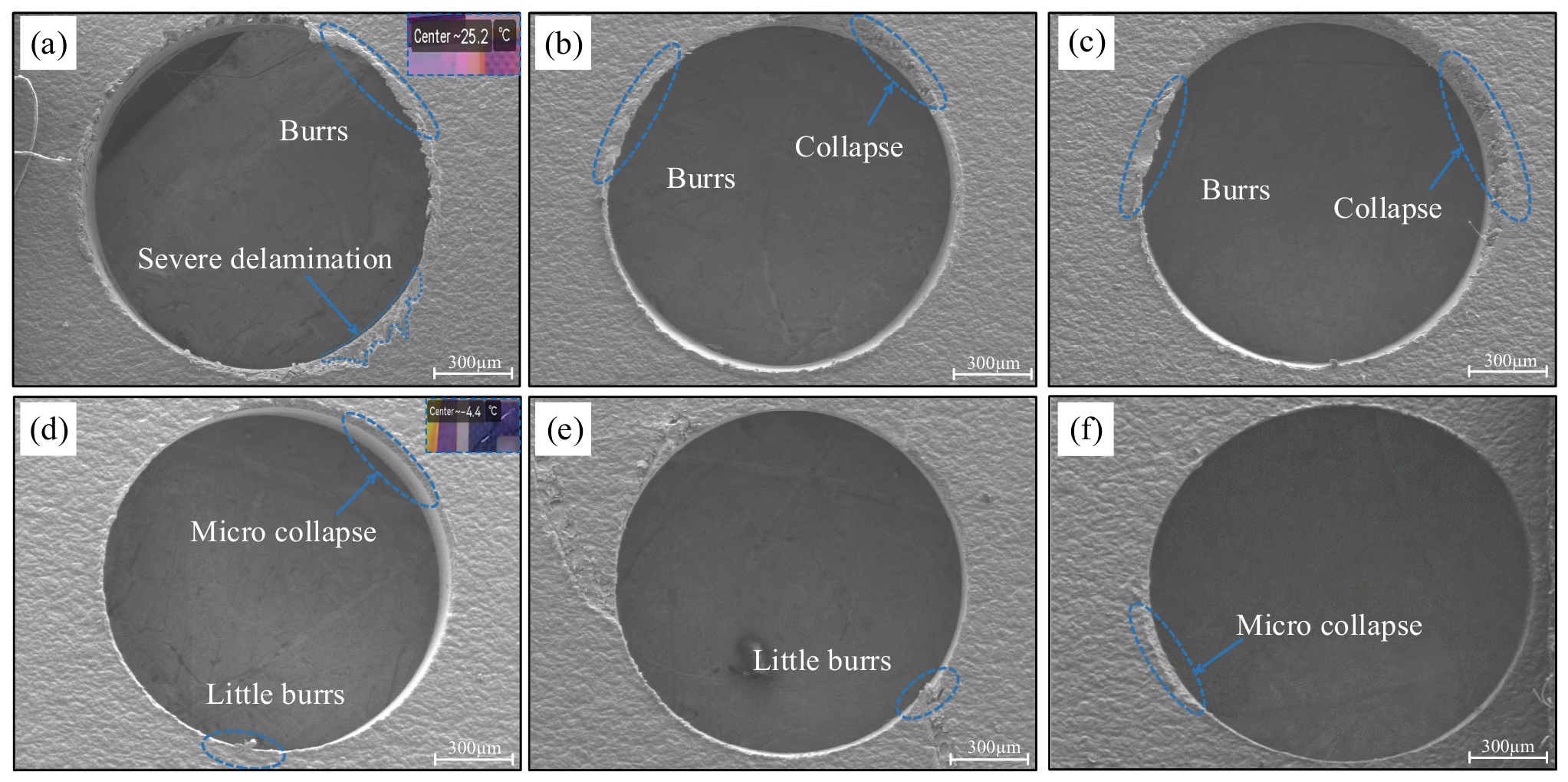
As shown in Figure 4a, severe cavity defects on the hole-wall surface and pronounced exit delamination were observed under conventional dry drilling at a spindle speed of 400 r/min. Similarly, Figure 4b reveals significant cavity defects and fiber tearing on the hole-wall surface at 1200 r/min. The formation of cavity defects can be attributed to the initiation of fiber–matrix interfacial debonding during drilling, followed by fiber fracture induced by bending and shear stresses. Under the continuous action of high drilling forces, cavities are eventually generated on the hole-wall surface and are accompanied by the accumulation of fiber–matrix debris. During the drilling process, the compressive and thrust forces exerted by the drill may exceed both the interfacial bonding strength between carbon fibers and the resin matrix and the interlaminar shear strength of the laminate. Consequently, interlaminar delamination and fiber–matrix debonding are induced. These damage mechanisms become more severe when the fiber orientation is perpendicular to the cutting direction, resulting in an increased tendency for interfacial failure and delamination propagation. As shown in Figure 4c, the number and size of cavity defects on the hole-wall surface were noticeably reduced under conventional dry drilling at 2000 r/min. In contrast, the hole-wall morphology obtained under ice-supported drilling exhibited significantly improved quality. As illustrated in Figure 4d, only slight fiber tearing was observed near the hole exit at 400 r/min, while no obvious cavity defects were detected. At 1200 r/min (Figure 4e), a small amount of resin debris remained on the hole-wall surface, whereas cavity defects were largely eliminated. At 2000 r/min (Figure 4f), only a few shallow cavities were observed, and the hole-wall surface appeared relatively smooth without noticeable damage. Comparison of Figure 4d–f demonstrates that, under identical spindle-speed conditions, the ice-supported drilling method significantly reduced both the number and depth of cavity defects on the hole-wall surface. Moreover, major drilling-induced damages, including delamination, fiber pull-out, matrix spalling, and exit tearing, were effectively suppressed. This improvement can be attributed to the combined cooling and supporting effects of the ice layer. The reduced drilling temperature alleviated thermally induced interfacial degradation, while the backing support provided by the ice enhanced the stiffness of the laminate near the hole exit, thereby reducing interlaminar shear damage and suppressing delamination propagation. As a result, superior hole-wall integrity and overall structural continuity were achieved after drilling. The bright contrast observed in some SEM images was mainly attributed to localized charging effects during SEM observation, which may be related to the heterogeneous electrical conductivity of CFRP. Fractured fiber edges and attached debris may also contribute to enhanced secondary electron emission and brighter contrast. These bright regions were not considered as independent damage features in the hole-wall quality evaluation. Instead, the hole-wall quality was assessed based on identifiable morphological characteristics, including cavities, fiber pull-out, matrix spalling, tearing, and material loss.

3.2. Analysis of Hole Surface Quality and Damage Characteristics

To analyze the effect of different machining parameters on the hole-entry quality of CFRP, the hole-entry morphologies under various drilling conditions were observed and compared, as shown in Figure 5. The results indicate that, under conventional dry drilling, the hole entries produced at different spindle speeds exhibited machining defects to varying degrees, and the hole-edge profiles were relatively unclear. As shown in Figure 5a, when the spindle speed was 400 r/min, obvious burrs and severe delamination were observed at the hole entry, accompanied by poor hole roundness. This can be mainly attributed to the low cutting speed at a low spindle speed, which intensified the extrusion and tearing effects of the cutting edge on the fiber bundles. As a result, material removal was dominated by extrusion-induced damage, leading to aggravated hole-edge defects. As shown in Figure 5b,c, when the spindle speed increased to 1200 r/min and 2000 r/min, the cutting process became more stable and the degree of hole-entry delamination was reduced. However, obvious burrs were still observed along the hole edge, together with local fiber-collapse defects. This indicates that increasing the spindle speed alone can partially reduce damage, but it is difficult to fundamentally suppress the formation of hole-entry defects. In contrast, after the application of ice-supported drilling, the hole-entry quality was significantly improved at all spindle speeds. As shown in Figure 5d, only slight burrs and local micro-fiber collapse were observed at 400 r/min. As shown in Figure 5e, when the spindle speed increased to 1200 r/min, the hole edge remained nearly intact, with only minor burr formation. At 2000 r/min, as shown in Figure 5f, only a small amount of micro-fiber collapse appeared at the hole entry, and the burr defects were further reduced. Overall, the hole entries obtained by ice-supported drilling exhibited clearer and more complete profiles, with smoother and more continuous hole-edge contours. No large-scale fiber tearing or obvious delamination was observed, and the roundness accuracy of the hole entry was significantly improved. This improvement is mainly associated with the thermal-regulation effect provided by the ice-supported condition. Previous studies on cryogenic drilling and machining of CFRP composites have demonstrated that the reduced temperature environment can suppress thermal softening of the epoxy matrix, improve matrix stiffness, and maintain a more stable fiber–matrix interaction during material removal [24,25]. Therefore, the reduced temperature response during drilling may contribute to maintaining a more stable fiber–matrix interaction and reducing excessive matrix deformation during cutting. Meanwhile, the ice support absorbed cutting heat and effectively reduced the temperature in the machining zone, thereby suppressing the formation of burrs, delamination, and collapse defects. Therefore, compared with conventional dry drilling, ice-supported drilling can significantly improve the hole-entry machining quality of CFRP and reduce the adverse influence of spindle-speed variation on hole-entry morphology.
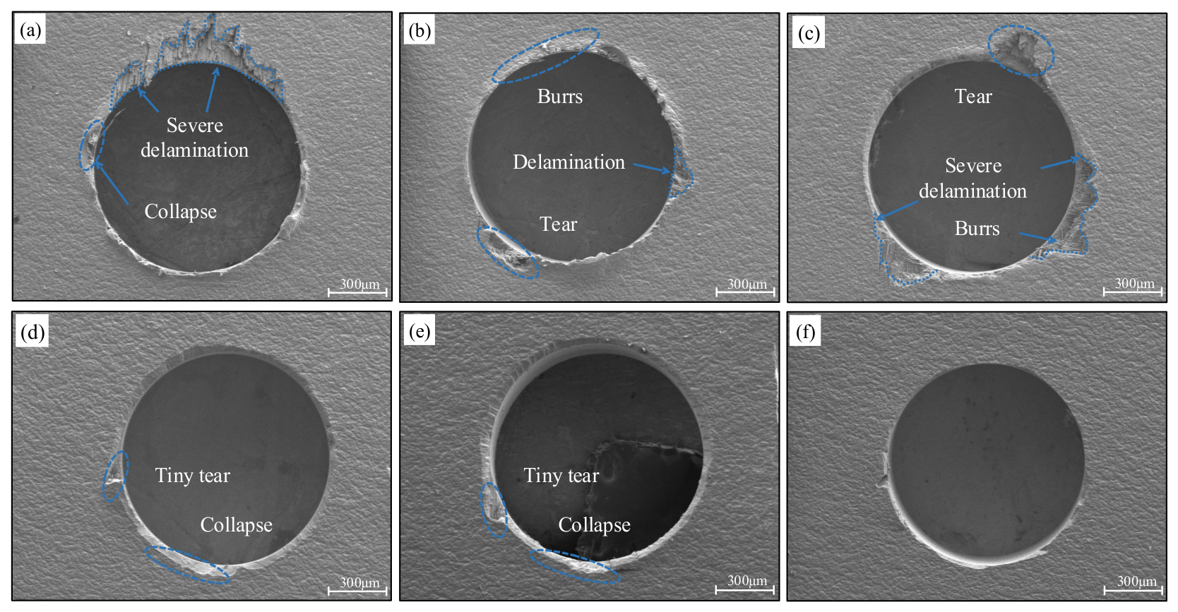
To analyze the effect of different machining parameters on the hole-exit quality of CFRP, the hole-exit morphologies under different drilling conditions were systematically observed and compared. The results show that obvious machining defects appear at the hole exit under conventional dry drilling. As shown in Figure 6a, when the spindle speed is 400 r/min, the hole-exit edge profile is unclear, accompanied by severe delamination and obvious fiber collapse. The damage region around the hole exit is large and irregular. With the increase in spindle speed to 1200 r/min, as shown in Figure 6b, the hole-exit edge quality is improved. Only slight burrs and delamination can be observed in local regions, and the overall roundness and integrity of the hole exit are better than those obtained at the low spindle speed. However, when the spindle speed is further increased to 2000 r/min, as shown in Figure 6c, relatively severe delamination and local fiber tearing still occur at the hole exit. Compared with conventional dry drilling, the hole-exit quality obtained by ice-supported drilling is significantly improved at all spindle speeds. As shown in Figure 6d, only slight tearing and local micro-collapse are observed at 400 r/min. At 1200 r/min, as shown in Figure 6e, the hole edge becomes smoother, and only slight burr formation can be observed. When the spindle speed reaches 2000 r/min, as shown in Figure 6f, the hole exit remains complete, the hole-exit boundary is clear and continuous, and no obvious defects are observed, indicating the best hole roundness and surface quality. This improvement can be attributed to the low-temperature environment and supporting effect provided by ice-supported drilling. The improvement in hole-exit quality is mainly associated with the mechanical constraint provided by the ice layer beneath the CFRP laminate. During drilling breakthrough, the remaining uncut layer becomes increasingly susceptible to bending deformation under axial loading due to its reduced thickness. Previous studies on backing-supported drilling have demonstrated that additional support beneath composite laminates can increase the critical thrust force required for delamination initiation and restrict deformation of the exit region [16]. The ice layer acts as a temporary backing medium, reducing the tendency for interlaminar crack opening and propagation. In addition, the thermal-regulation effect of the ice-supported condition may contribute to maintaining a more stable material-removal process. As a result, the formation of burrs, delamination, and fiber tearing is effectively suppressed. Therefore, ice-supported drilling can not only improve the surface quality and integrity of CFRP hole exits but also reduce the adverse influence of machining-parameter variation on hole morphology, providing an effective process for high-precision CFRP hole machining.
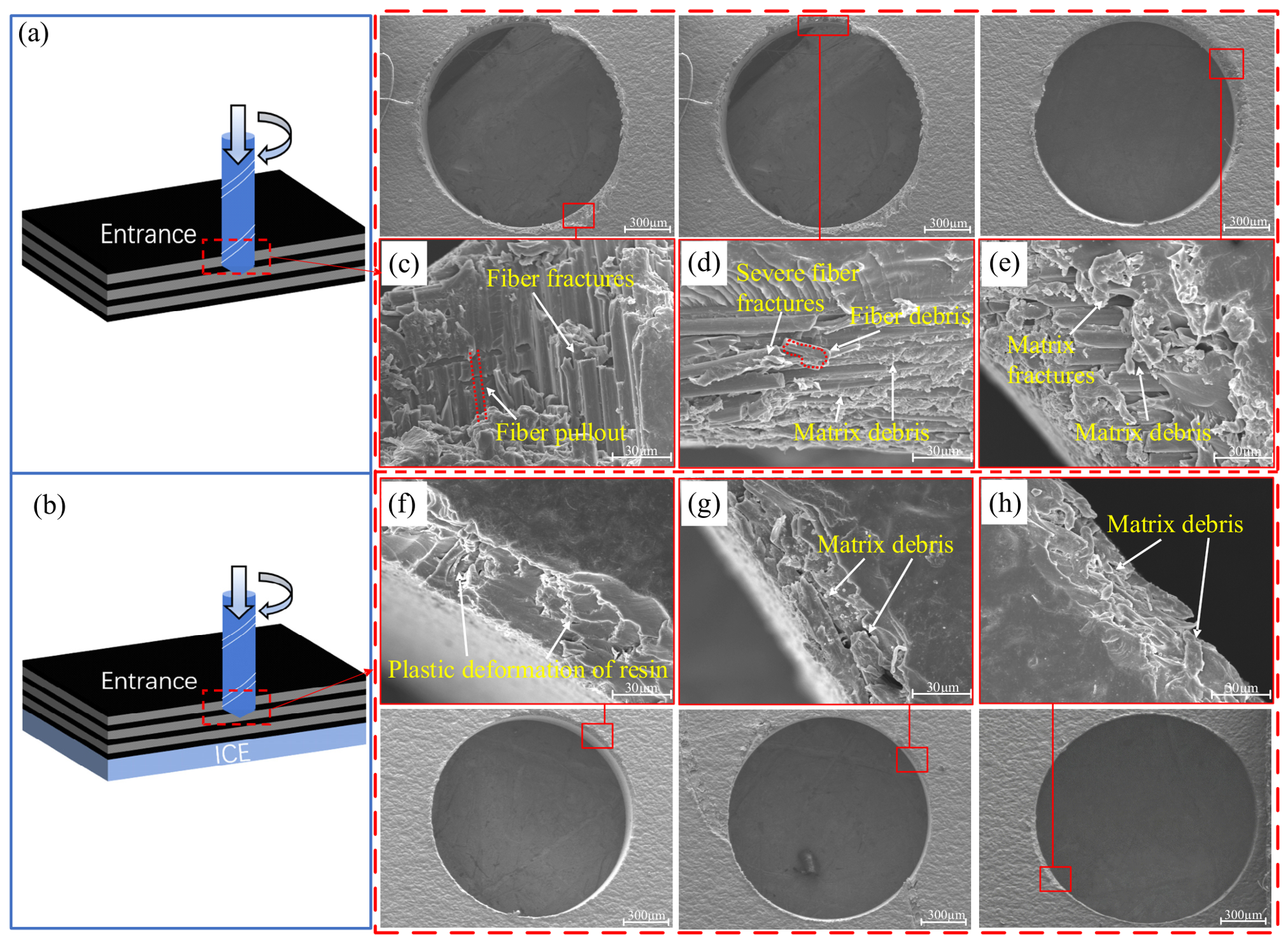
Figure 7a and Figure 7b show the schematic diagrams of the CFRP hole-entry damage mechanisms in conventional dry drilling and ice-supported drilling, respectively. For conventional dry drilling at 400 r/min, as shown in Figure 7c, the main damage at the CFRP hole entry is characterized by severe interlaminar delamination, irregular tensile–shear mixed fracture of fibers, large-area fiber–matrix interfacial debonding, and resin matrix fragmentation. It can be observed from the microscopic morphology that obvious interlaminar separation occurs perpendicular to the ply direction, indicating severe delamination. The fracture surfaces of the carbon fibers are uneven, and no regular shear-fracture features are observed. In addition, large-area debonding occurs between the fibers and the resin matrix. The matrix presents fragmentation-type damage, accompanied by a large amount of fiber pull-out and fiber fracture. For conventional dry drilling at 1200 r/min, as shown in Figure 7d, the dominant damage at the CFRP hole entry is large-scale Mode I/II mixed-mode interlaminar delamination, continuous fiber-bundle pull-out, plastic tearing of the resin matrix, and fiber/resin debris. Clear ply peeling and interlaminar gaps can be observed from the microscopic morphology. A large number of carbon fiber bundles are pulled out from the resin matrix as a whole, accompanied by splitting of the fiber bundles. Meanwhile, the resin matrix exhibits large-area tearing deformation and cracking along the fiber direction. For conventional dry drilling at 2000 r/min, as shown in Figure 7e, no severe interlaminar delamination is observed at the CFRP hole entry. The damage is mainly manifested as resin matrix tearing and resin debris, accompanied by a small amount of fiber fracture. Compared with Figure 7c,d, the surface quality is significantly improved. For ice-supported drilling at 400 r/min, as shown in Figure 7f, localized resin smearing and slight plastic deformation can be observed on the machined surface. Compared with conventional dry drilling, the resin matrix remains relatively continuous, and no obvious brittle fracture, matrix peeling, or large-scale debris accumulation is observed. This indicates that the low-temperature environment provided by the ice layer helps suppress severe matrix fragmentation and fiber–matrix interfacial debonding. For ice-supported drilling at 1200 r/min, as shown in Figure 7g, no severe mesoscopic damage is observed at the CFRP hole entry. Only a small amount of matrix debris and slight resin smearing appear near the entry edge. For ice-supported drilling at 2000 r/min, as shown in Figure 7h, the hole-entry edge profile remains relatively intact, and the resin matrix maintains good continuity. Only a small amount of matrix debris is observed, without obvious fiber fracture, fiber pull-out, or severe interfacial debonding. As shown in Figure 7g,h, the hole-entry edge region exhibits relatively intact ply bonding, with no obvious interlaminar delamination, fiber pull-out, edge chipping, or burr formation. These microscopic observations indicate that ice-supported drilling can effectively suppress fiber fracture and interlaminar delamination at the hole entry, thereby significantly improving the machined surface quality of CFRP holes. This reduction in damage can be explained by the altered thermo-mechanical environment under ice-supported drilling. Compared with conventional dry drilling, the ice-supported condition provides a more stable machining environment by reducing thermal accumulation and restricting deformation of the thin CFRP laminate. Consequently, severe fiber–matrix debonding and matrix fragmentation are reduced during cutting.
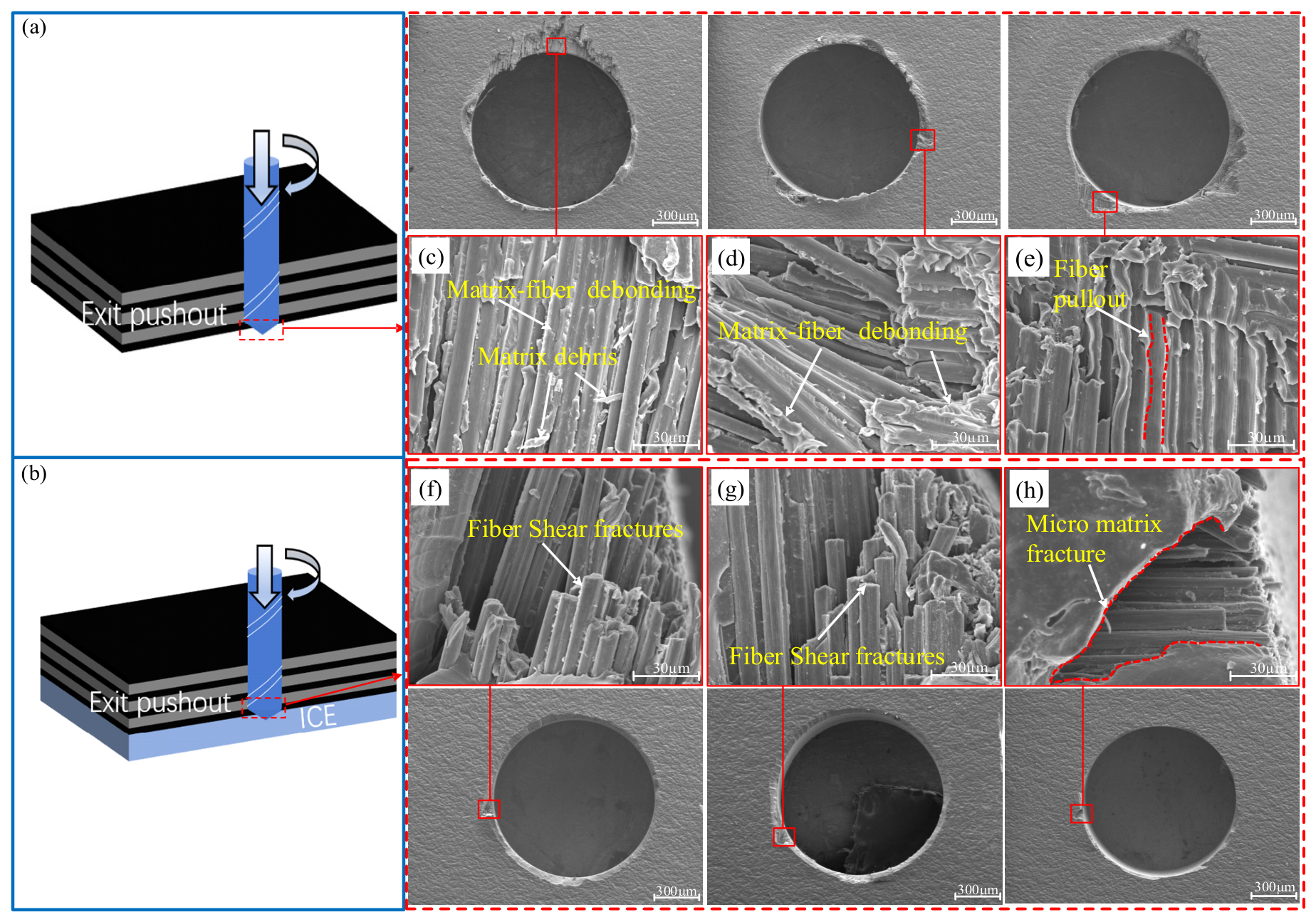
Figure 8a and Figure 8b show the schematic diagrams of the hole-exit damage mechanisms of CFRP in conventional dry drilling and ice-supported drilling, respectively. For conventional dry drilling at 400 r/min, as shown in Figure 8c, severe interfacial damage can be observed at the CFRP hole exit, which is mainly characterized by fiber–matrix interfacial debonding and matrix debris. Extensive fiber–matrix interfacial debonding occurs, and a large number of continuous carbon fiber bundles are pulled out from the resin matrix. Obvious push-out separation occurs between adjacent plies, while extensive cracking of the resin matrix along the fiber direction is also observed. In addition, transverse splitting of fiber bundles appears at the hole exit, indicating a typical push-out failure mode during CFRP drilling. For conventional dry drilling at 1200 r/min, as shown in Figure 8d, severe push-out interlaminar delamination can also be observed at the CFRP hole exit. The damage is mainly manifested as fiber–matrix interfacial debonding. The carbon fiber bundles are peeled off as a whole and present irregular bending, fracture, and deformation. The fracture surfaces are irregular and show tensile–shear mixed fracture characteristics, without neat shear-fracture features. Meanwhile, the resin matrix exhibits fragmentation-type failure, and complete debonding occurs at the fiber–matrix interface. A large number of fiber bundles are separated from the plies as a whole, resulting in a significant increase in the damaged area and damage severity at the hole exit. For conventional dry drilling at 2000 r/min, as shown in Figure 8e, a large amount of fiber pull-out can be observed at the CFRP hole exit. Many carbon fibers are pulled out axially from the resin matrix, forming continuous pits and grooves along the fiber direction. This phenomenon is mainly attributed to thermal softening of the resin matrix caused by cutting heat, which weakens the fiber–matrix interfacial bonding and promotes interfacial debonding. In addition, the non-uniform shear and tensile loads exerted by the drill cutting edge on the fibers cause the fibers that are not completely cut to be peeled away from the matrix. As shown in Figure 8f and Figure 8g, corresponding to ice-supported drilling at 400 r/min and 1200 r/min, respectively, a small amount of fiber pull-out and transverse fracture of fiber bundles can still be observed at the machined hole exit. However, compared with conventional dry drilling, ice-supported drilling effectively suppresses the propagation of fiber fracture. The damage area is significantly reduced, and no complete interfacial debonding between the carbon fibers and the resin matrix is observed. The microscopic morphology of ice-supported drilling at 2000 r/min, as shown in Figure 8h, further confirms the suppression effect of this method on hole-exit damage. The overall damaged area at the hole exit is relatively small. Only slight local shedding of the resin matrix can be observed, and the exposed fiber bundles remain regularly arranged. The significantly reduced damage observed under ice-supported drilling is mainly attributed to the enhanced support condition at the hole exit. In conventional dry drilling, the absence of external support allows the remaining laminate layer to deform under the axial drilling load, promoting interlaminar separation and fiber pull-out. In contrast, the ice layer acts as a temporary backing medium, providing constraint against downward deformation and reducing the opening tendency of interlaminar cracks. Moreover, the thermal-regulation effect of the ice layer may further contribute to maintaining fiber–matrix integrity by reducing thermal softening of the polymer matrix.

3.3. Tool Wear

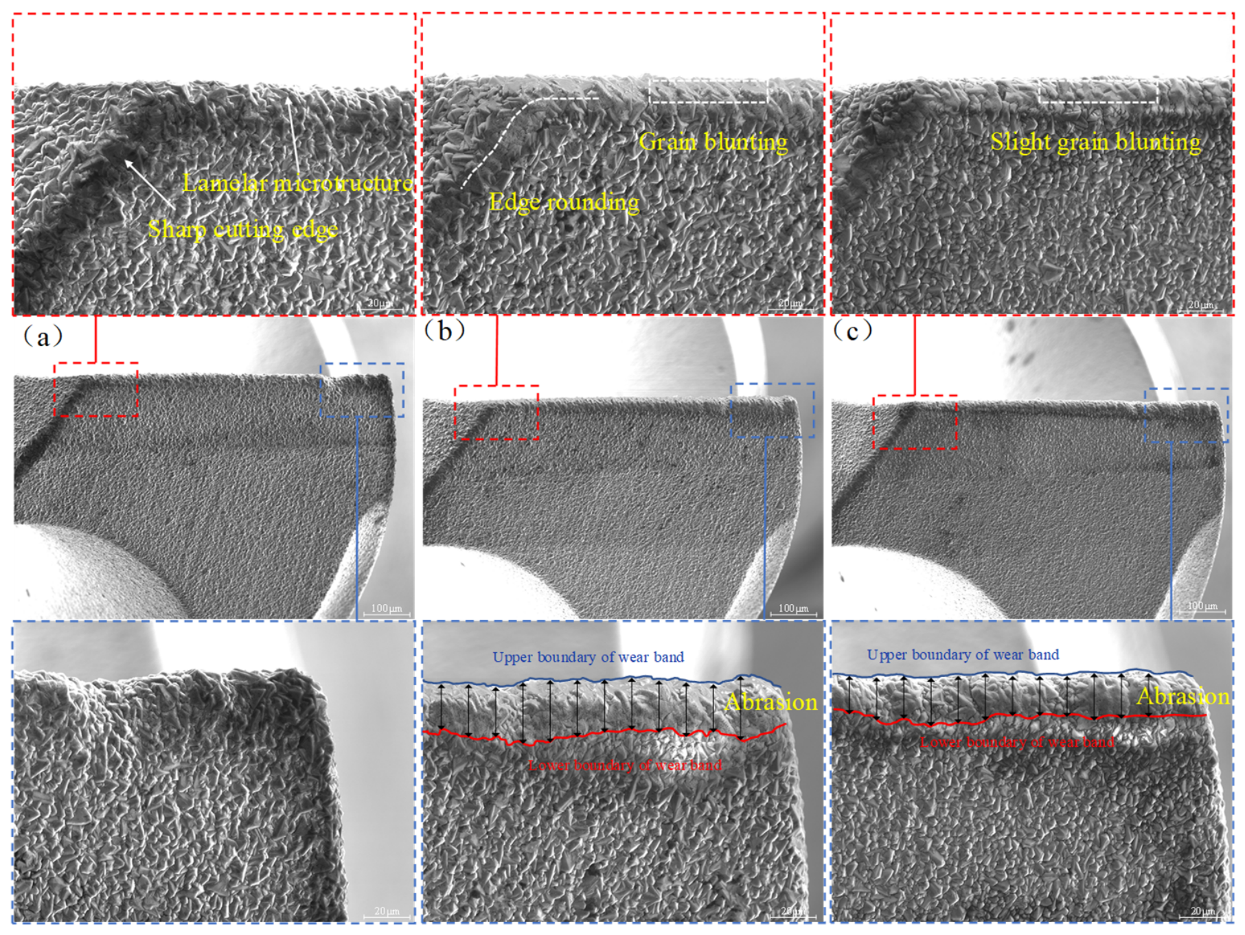
Figure 9 shows the SEM images of the cutting edges of the original diamond-coated drill, the drill used in conventional dry drilling at 2000 r/min, and the drill used in ice-supported drilling at 2000 r/min. As shown in Figure 9a, the diamond grains on the original tool surface were uniformly distributed and exhibited a typical lamellar microstructure. The grain boundaries were clear, the grain edges remained intact, and the cutting edge was sharp. No obvious wear marks or surface defects were observed, indicating that the diamond coating possessed good initial integrity and surface quality. As shown in Figure 9b, after conventional dry drilling at 2000 r/min, obvious morphological changes occurred in the cutting-edge region. The cutting edge was rounded to varying degrees, and a continuous wear land was formed at the edge tip. The sharp features of some diamond grains became weakened, accompanied by grain blunting. Meanwhile, local surface flattening and abrasion marks were observed, indicating that the tool was subjected to continuous friction during drilling, which gradually wore the surface diamond grains. The increased rounding of the cutting edge indicates a reduction in tool sharpness and potential degradation of cutting performance. In contrast, as shown in Figure 9c, after ice-supported drilling at 2000 r/min, the diamond grains on the tool surface maintained relatively high integrity. The grain profiles in the cutting-edge region remained clear, and only slight grain blunting was observed. The degree of grain flattening was relatively low, indicating that the low-temperature environment suppressed, to some extent, the accumulation of frictional heat and the associated wear process. Therefore, after drilling 20 holes at 2000 r/min, the tool used under conventional dry drilling conditions exhibited more pronounced grain flattening, surface abrasion, and cutting-edge blunting. Following a boundary-based wear characterization approach adapted from Hrechuk and Bushlya [27], the upper and lower boundaries of the wear band were identified from the enlarged SEM images. Twelve equally spaced measurement lines were arranged within the examined cutting-edge segment, and the mean wear-band width was calculated from the local widths measured between the two boundaries. The mean wear-band width was 22.68 μm under conventional dry drilling and 18.09 μm under ice-supported drilling, corresponding to a reduction of approximately 20.22%. In contrast, the tool used under ice-supported conditions showed less severe wear features, indicating that the ice-supported condition alleviated the wear severity of the diamond-coated drill under the investigated short-term machining condition.

3.4. Drilling Temperature

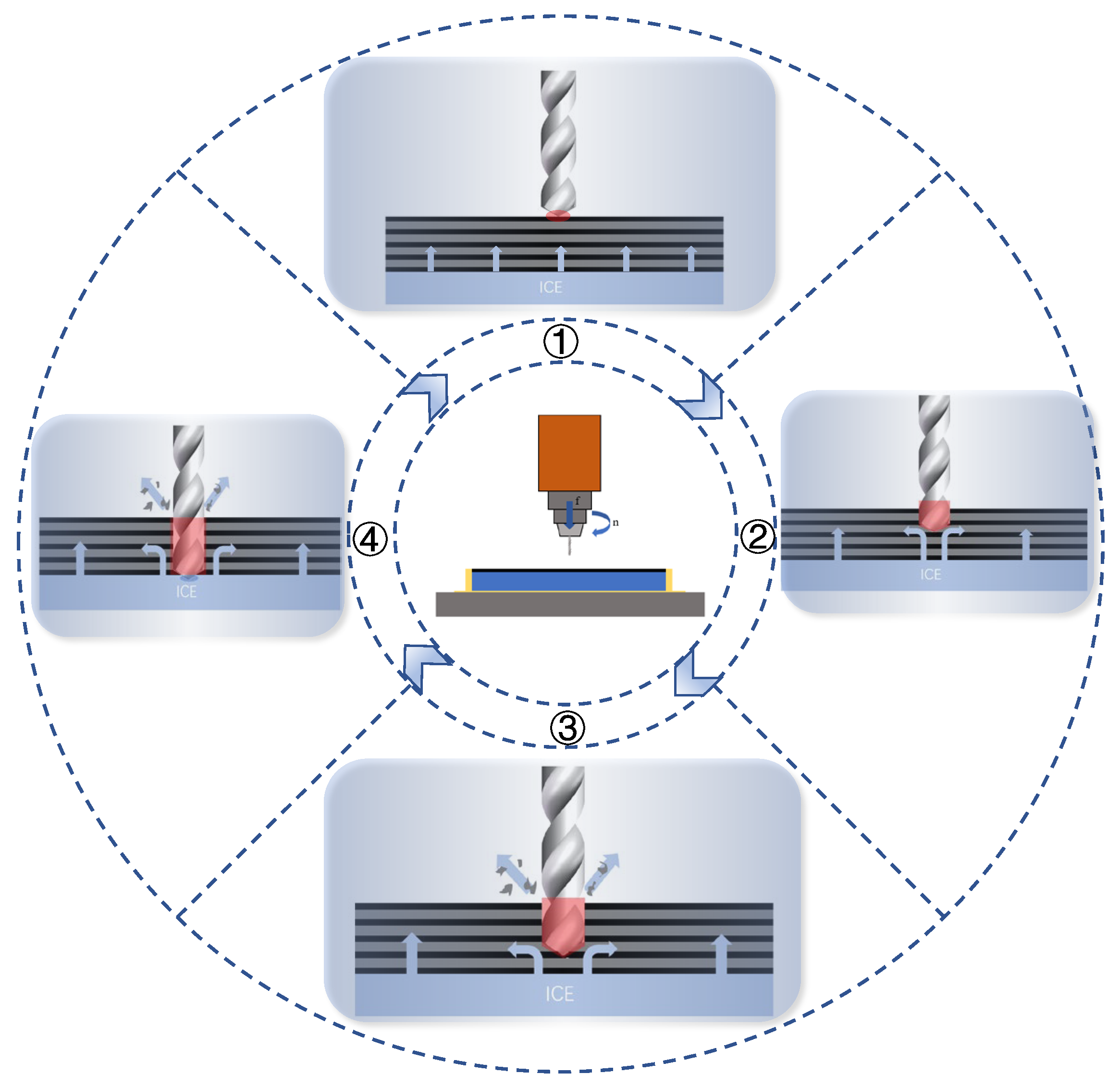
In CFRP drilling, temperature is a key indicator for evaluating machining performance. Figure 10 illustrates the heat-source regions and heat dissipation during the CFRP drilling process. Four different drilling stages can be observed. In stage ①, corresponding to the initial drilling stage, the chisel edge of the drill contacts and compresses the upper surface of the CFRP. At this stage, the cutting thickness is small, and both deformation-induced heat and frictional heat are in the initial accumulation stage. Therefore, the heat generation rate is relatively low, and the generated heat is mainly concentrated in the contact region between the drill and the material. Meanwhile, the ice layer beneath the CFRP laminate provides an overall supporting constraint and helps reduce the vibration and deformation tendency of the workpiece during drill entry, thereby limiting additional frictional heat generation. In stage ②, corresponding to the stable drilling stage, the main cutting edges of the drill continuously remove the CFRP material. The heat generated by material deformation in the primary shear zone and the frictional heat between the chips and the rake face of the drill increase continuously. This stage is the main heat-generation stage during the entire drilling process. The ice layer on the back side absorbs a large amount of drilling heat through solid–liquid phase transformation, thereby partially dissipating the generated heat. In stage ③, corresponding to the critical breakthrough stage, sliding friction occurs between the flank face of the main cutting edge and the newly formed hole wall. This process includes abrasive wear caused by the fractured ends of carbon fibers and stick–slip friction of the resin matrix. The mixed debris composed of carbon fibers and resin generated during drilling flows out along the rake face of the drill. The carbon fibers induce abrasive friction on the rake face, while the resin matrix undergoes stick–slip friction, resulting in substantial frictional heat. Part of the heat is conducted through the tool, and part is transferred into the surface layer of the workpiece. Meanwhile, a portion of the heat is carried away by the chips, and another portion is continuously absorbed by the ice layer as the cutting heat transfers toward the exit layer. As a result, the temperature of the exit layer is maintained within a relatively low range, which helps suppress resin thermal softening and maintain the fiber–matrix interfacial bonding strength. In stage ④, corresponding to the complete breakthrough stage, the drill fully penetrates the material, and the deformation-induced heat in the primary shear zone gradually disappears. Heat generation is mainly attributed to friction between the drill margin and the machined hole wall, as well as the transfer of residual heat from inside the drill to the hole wall. The ice–water mixture formed on the back side of the material continuously absorbs the residual heat inside the material and on the hole wall through heat conduction and convective heat transfer, thereby preventing heat accumulation inside the material and avoiding thermal damage to the resin matrix. Meanwhile, the continuous supporting effect prevents tearing of the exit layer at the moment of breakthrough, further reducing additional heat generation.
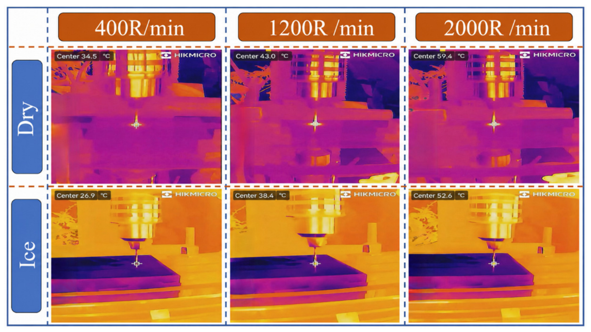
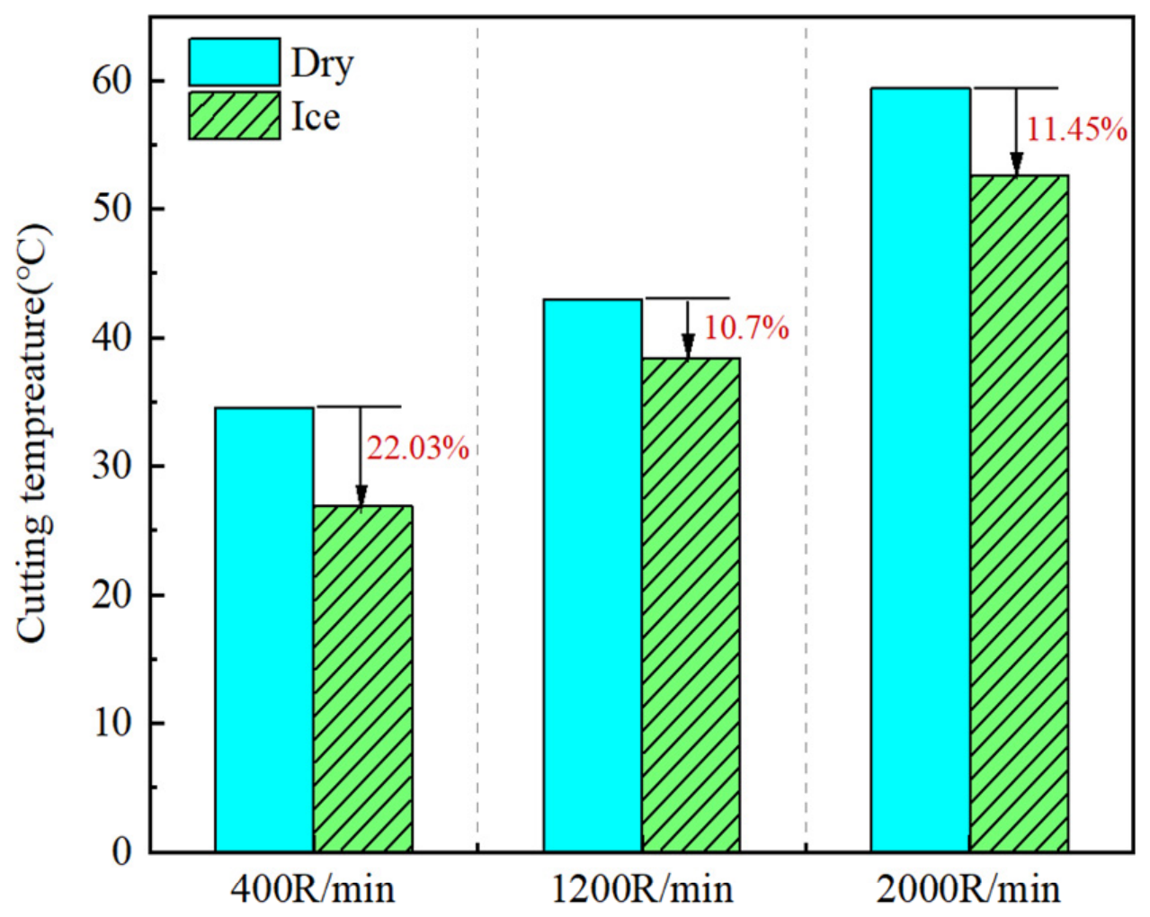
In CFRP drilling, temperature is a key indicator for evaluating machining performance. Figure 11 shows the infrared thermal imaging results of CFRP drilling under different drilling conditions. The reference temperature in drilling is generally taken as the maximum temperature reached during the process. Figure 12 presents the variation trend of the maximum cutting temperature under different spindle speeds and drilling modes. As shown in the figure, the drilling temperature under both drilling modes increased monotonically with increasing spindle speed. At the three spindle speeds, the drilling temperature obtained by ice-supported drilling was reduced by 22.03%, 10.70%, and 11.45%, respectively, compared with that obtained by conventional dry drilling. This temperature reduction is considered to be associated with the thermal regulation effect of the ice layer beneath the CFRP laminate. Heat transferred toward the hole-exit region may be partially absorbed through the melting and solid–liquid phase transformation of the ice, while the resulting meltwater may further contribute to heat dissipation through additional heat-transfer pathways. Because the present infrared measurements only characterize the overall temperature response, the respective contributions of these mechanisms cannot be independently quantified. Therefore, the observed temperature reduction reflects the overall thermal-regulation capability of the ice-supported condition. However, at high spindle speeds, the cutting heat generation rate increases sharply, which gradually reduces the effectiveness of the available thermal regulation provided by the ice-supported system. Therefore, the relative cooling efficiency decreases to some extent.

3.5. Delamination Characterization

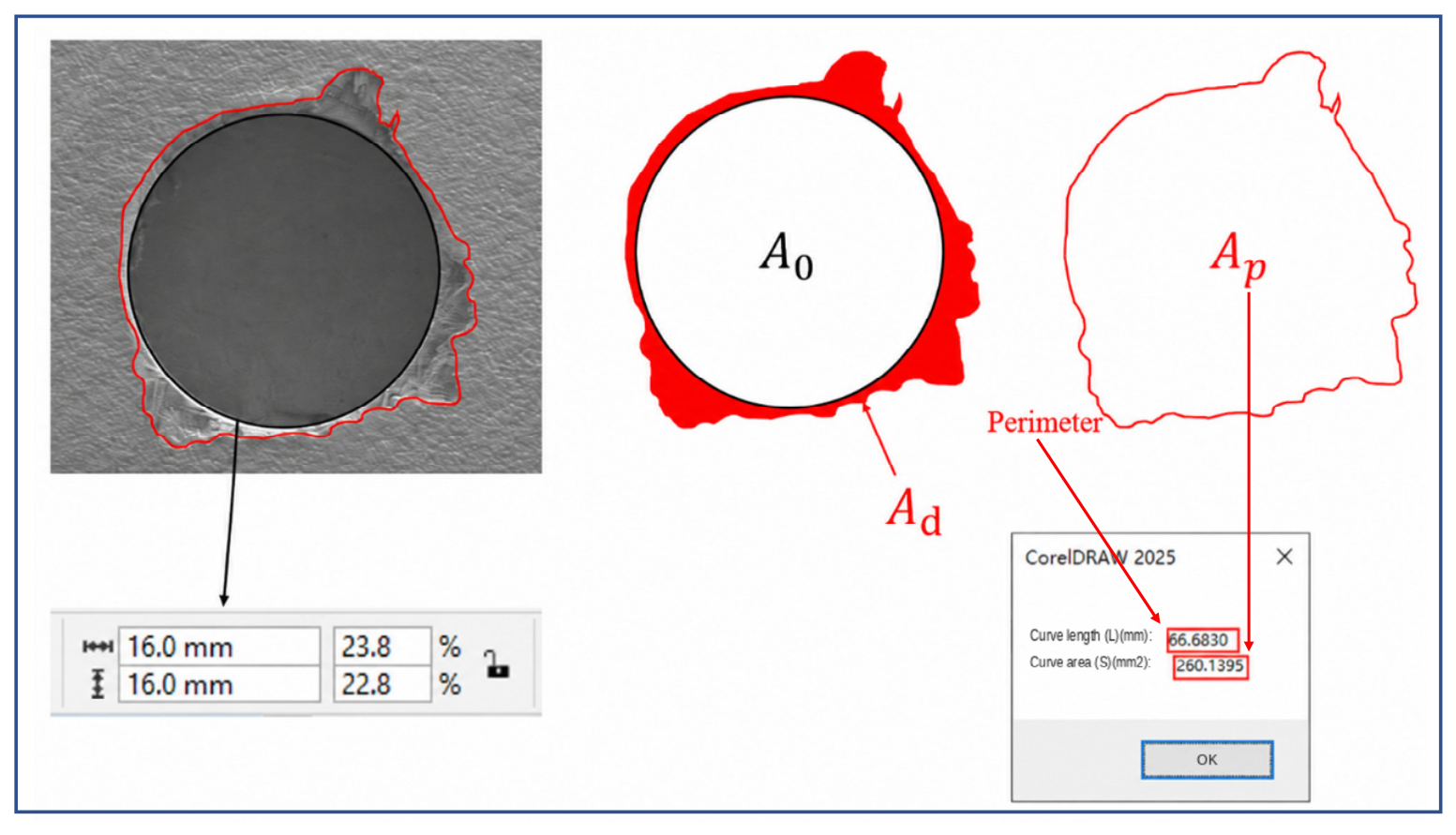
Delamination damage evaluation during CFRP drilling was performed using the AutoCAD image processing (ACIP) technique proposed by Khashaba [28]. As shown in Figure 13, the ACIP procedure for analyzing delamination images of drilled holes in CFRP is briefly illustrated. The images of the drilled-hole exit were obtained using scanning electron microscopy. After importing the images into CorelDraw Graphics Suite 2025 software, a reference circle was drawn using the “Object Size” tool, with the width and height both set to 16 mm. The nominal hole area (A0), hole perimeter, and the area enclosed by the perimeter (Ap) were then obtained using the following CorelDraw tools: “Quick Trace”, “Ungroup All Objects”, and “Combine into a single fill-and-outline curve”. Finally, the delamination area (Ad) was determined by subtracting the nominal hole area (A0) from the area enclosed by the perimeter (Ap). Although 20 holes were drilled under each machining condition, 5 holes distributed at fixed intervals throughout the drilling sequence were selected for quantitative image analysis. The same sampling positions and image-analysis criteria were used for all experimental conditions. The results are presented as mean ± standard deviation (n = 5).
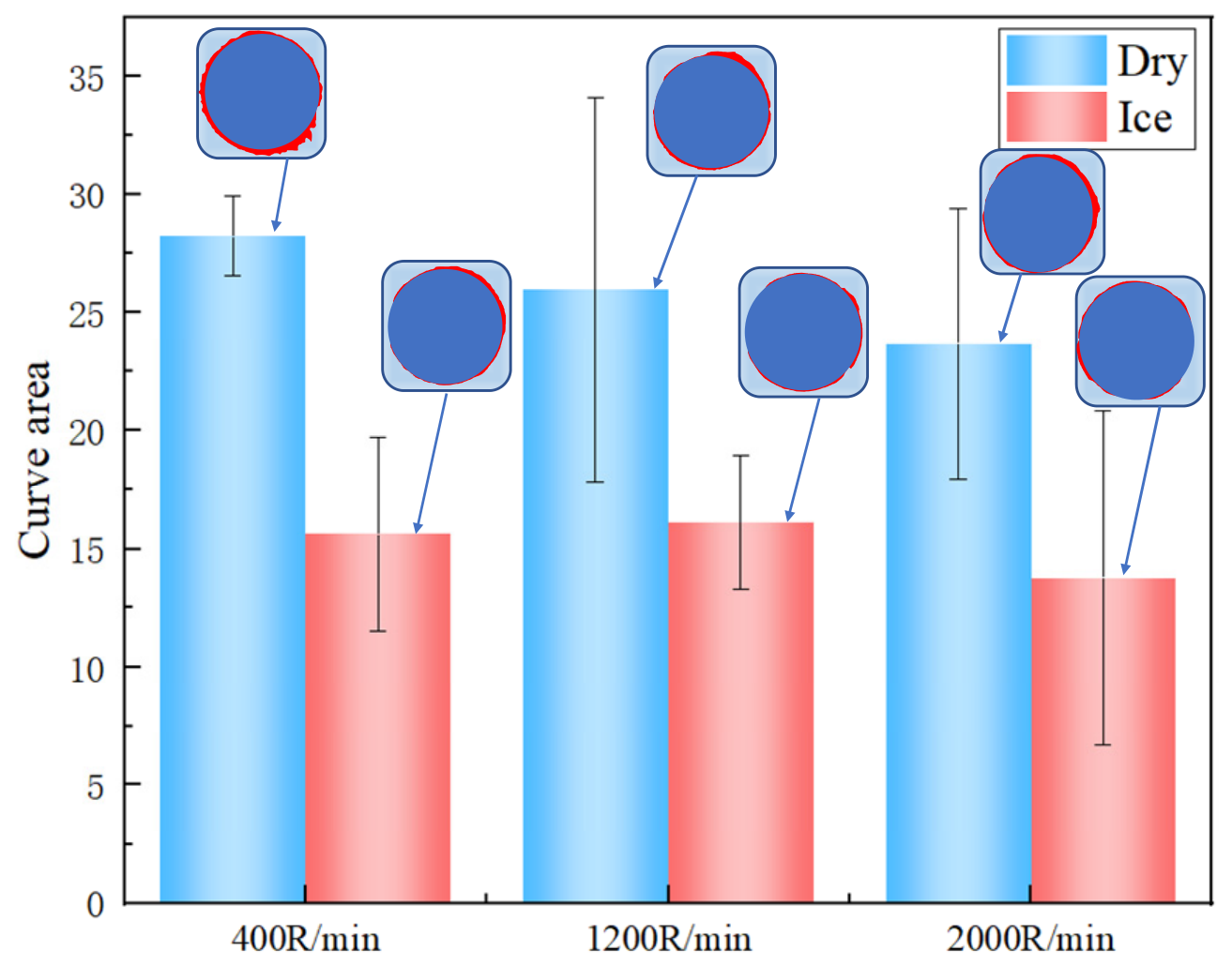
As shown in Figure 14, the ACIP-based results for the drilled-hole entry demonstrate that ice-supported drilling produced a smaller mean delamination area than conventional dry drilling at all tested spindle speeds. Under dry-drilling conditions, the red damage contours extended farther beyond the nominal hole boundary and exhibited relatively irregular profiles. In contrast, the contours obtained under ice-supported drilling were more compact, remained closer to the nominal hole perimeter, and showed smoother boundaries. Based on the mean values obtained from five sampled holes under each condition, ice-supported drilling reduced the hole-entry delamination area by 44.68%, 37.93%, and 41.86% at spindle speeds of 400, 1200, and 2000 r/min, respectively, compared with conventional dry drilling. The corresponding results are presented as mean ± standard deviation (n = 5). These results indicate that ice-supported drilling can reduce hole-entry delamination under the investigated drilling conditions.
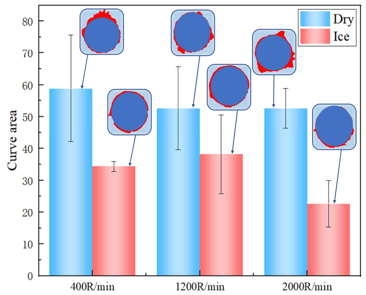
As shown in Figure 15, the ACIP-based results for the drilled-hole exit demonstrate that ice-supported drilling produced a smaller mean delamination area than conventional dry drilling at all tested spindle speeds. Under dry-drilling conditions, the red damage contours extended farther beyond the nominal hole boundary and exhibited relatively large and irregular profiles. In contrast, the contours obtained under ice-supported drilling were more compact, remained closer to the nominal hole perimeter, and showed smoother boundaries. Based on the mean values obtained from five holes selected at fixed intervals throughout the drilling sequence under each condition, ice-supported drilling reduced the hole-exit delamination area by 41.68%, 27.45%, and 57.04% at spindle speeds of 400, 1200, and 2000 r/min, respectively, compared with conventional dry drilling. The results are presented as mean ± standard deviation (n = 5). These results suggest that the additional backing constraint provided by the ice-supported condition contributes to reducing hole-exit delamination during CFRP drilling.

4. Theoretical Interpretation of the Ice-Support Mechanism

During CFRP drilling, the mechanical properties of the epoxy resin matrix are highly sensitive to temperature variation under the coupled thermo-mechanical effect. When the cutting temperature gradually approaches the glass transition temperature of the resin (Tg ≈ 120 °C), the resin matrix changes from the glassy state to the rubbery state. This leads to a decrease in matrix stiffness and further weakens the bonding ability of the fiber–matrix interface. It has been reported that obvious damage, such as matrix cracking, interfacial debonding, and interlaminar delamination, can occur in CFRP during temperature rise [29]. The SEM results reported in the literature show that when the temperature exceeds 150 °C, resin softening causes the fiber bundles to become loose and significantly weakens the fiber–matrix interfacial bonding strength. As a result, a large number of microcracks and interlaminar debonding defects begin to form. With a further increase in temperature, severe thermal softening and possible thermal degradation of the resin matrix may further weaken the fiber–matrix interface, resulting in extensive interfacial failure. In this case, the internal stress cannot be effectively transferred in the composite. Based on the above temperature-induced damage mechanism, it can be inferred that the thermal damage during drilling is mainly caused by resin thermal softening and interfacial degradation. The cutting heat generated during drilling reduces the load-bearing stability of the fiber–matrix interface, making the axial thrust more likely to induce typical hole-making defects, such as interlaminar cracking, fiber pull-out, and exit delamination. Therefore, the stability of the fiber–matrix interface plays an important role in determining the drilling quality of CFRP.
Under ice-supported drilling conditions, the low-temperature environment can effectively reduce the transient temperature rise in the cutting zone and prevent the resin matrix from approaching the glass transition region. As a result, the thermal softening effect of the resin is weakened, and the epoxy matrix can maintain relatively high glassy-state stiffness and interfacial bonding ability. According to the reported results [29], increasing temperature continuously reduces the interfacial load-transfer ability, whereas low-temperature conditions can improve the stability of the fiber–matrix interface and slow down the interfacial degradation process. Therefore, under the low-temperature effect, the cutting load can be transferred more uniformly between the fibers and the resin matrix. This reduces interfacial slip and local stress concentration, thereby suppressing crack initiation and interlaminar crack propagation. In addition, the support structure provides a local constraint to the hole-exit region, which can effectively reduce the bending deformation and interlaminar opening displacement caused by axial thrust. This effect is particularly important at the exit stage. At this stage, the thickness of the uncut layer gradually decreases, and the stability of the interlaminar structure is weakened, making peel-up instability more likely to occur. The supporting effect can increase the local stiffness of the exit region and reduce the tendency of interlaminar cracking induced by thrust force. Therefore, a synergistic effect is formed between the low-temperature environment and the support structure. The low-temperature environment mainly suppresses resin thermal softening and interfacial weakening, while the support structure mainly inhibits mechanical instability in the exit region. These two effects jointly reduce delamination damage and fiber tearing under thermo-mechanical coupling.
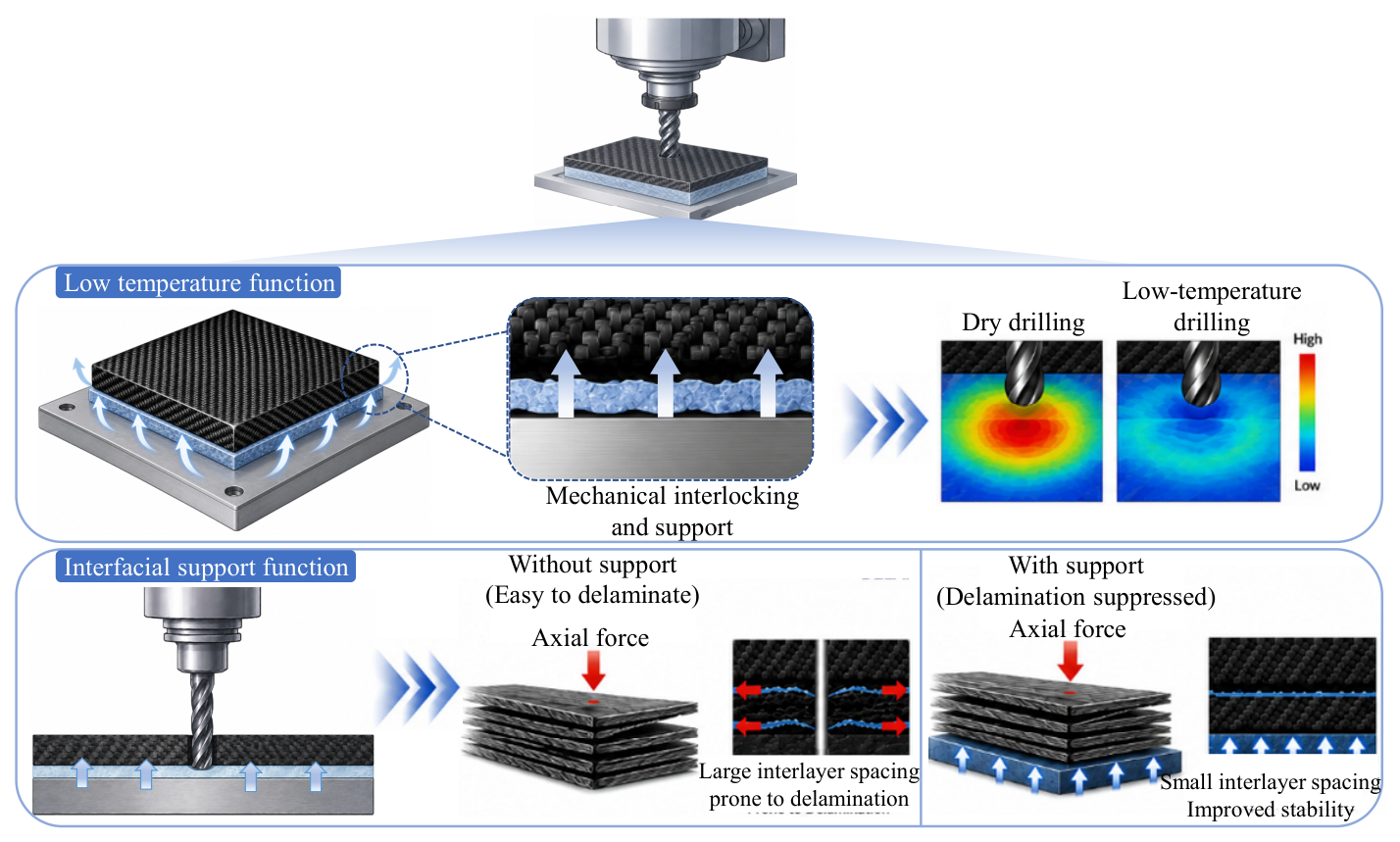
Figure 16 shows the schematic diagram of the ice-supported drilling principle. In this method, the ice layer is placed beneath the CFRP laminate. Owing to its special physical properties, the ice layer can absorb a large amount of drilling heat generated during drilling, thereby reducing resin thermal softening and interfacial weakening. Meanwhile, part of the heat transferred from the drilling zone can be dissipated through the ice layer and the meltwater., which helps to suppress thermal damage. During downward drilling, the ice layer provides an upward supporting force to the CFRP laminate. The supporting reaction provided by the ice layer can restrict the bending deformation tendency of the remaining uncut layer under drilling load, thereby suppressing delamination defects. After machining, the ice melts naturally without damaging the CFRP workpiece or causing environmental pollution. Therefore, ice-supported drilling is a more environmentally friendly and sustainable method for CFRP hole machining.
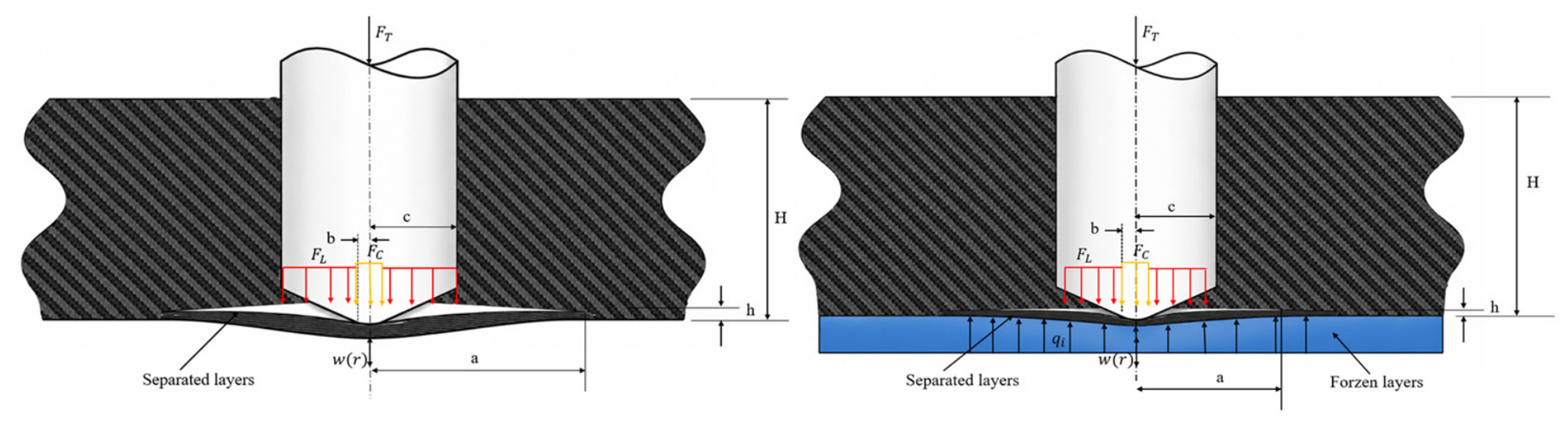
As the thrust force increases during drilling, the delamination at the hole exit of the CFRP component becomes more severe [13]. Therefore, reducing the thrust force plays a key role in suppressing delamination. Existing studies have mainly investigated the effects of passive backing support and active backing support on the delamination behavior of CFRP components [30]. In practical applications, passive backing support is relatively easy to implement. In this study, an innovative approach is proposed, in which an ice layer is used as a backing plate beneath the CFRP component. The ice layer not only provides additional mechanical constraint beneath the CFRP laminate but also reduces the observable drilling temperature through thermal regulation. As a result, the delamination at the hole exit of the CFRP component is more effectively suppressed. Figure 17 shows the theoretical model of hole-exit delamination in CFRP drilling under ice-supported conditions. In the model, FT is the axial thrust force of the drill, FC is the feed force acting on the chisel edge, FL is the feed force acting on the main cutting edge, and qi is the support reaction provided by the ice layer. In addition, w(r) denotes the deflection of the circular plate, a is the radius of the delaminated region, b is the radius of the chisel-edge region, c is the radius of the drilled hole, H is the thickness of the CFRP workpiece, and h is the remaining thickness at the hole exit.
When the twist drill approaches the exit side of the CFRP laminate, only an uncut layer with a remaining thickness of h is left at the lower surface of the workpiece. With the continuous feed of the drill, the stiffness of the remaining layer decreases rapidly. Under the action of thrust force, the remaining layer undergoes bending deformation, which further induces interlaminar delamination. The total axial thrust force of the drill FT is composed of the feed force acting on the chisel edge FC and that acting on the main cutting edges FL, which can be expressed as:
F T = F C + F L
Therefore, the hole-exit region during drilling can be divided into three regions: the chisel-edge loading region, the main-cutting-edge loading region, and the ice-layer support region. To obtain a tractable analytical description of the mechanical-support mechanism, the residual uncut layer at the hole exit was simplified as an equivalent isotropic axisymmetric thin plate. The purpose of this model is to interpret how the supporting reaction of the ice layer influences the bending deformation and delamination tendency of the residual layer and to predict the variation trends associated with drill radius, residual-layer thickness, and ice-support stiffness. The model is not intended to provide an exact numerical prediction of the absolute critical thrust force. Consequently, the orthotropic bending behavior and the fiber-orientation-dependent local stress distribution of the 0°/90° woven laminate are not explicitly considered. The remaining layer at the hole exit is simplified as an axisymmetric circular thin plate, and its bending stiffness can be expressed as [31]:
D = E h 3 12 ( 1 − v 2 )
where E is the elastic modulus of the laminate, and v is Poisson’s ratio. The chisel edge acts within the central region with a radius of b, while the main cutting edges act on the annular region of b ≤ r ≤ c. The delamination propagation radius at the hole exit is defined as a, satisfying the relationship b ≤ c ≤ a.
According to the Kirchhoff–Love thin plate theory, the remaining layer at the hole exit can be regarded as an axisymmetric circular plate. The deflection function w satisfies the biharmonic governing equation:
D ∇ 4 w = q ( r )
where D is the bending stiffness of the laminate, q(r) is the equivalent distributed load formed by the drilling load and the supporting reaction of the ice layer, and ∇ 4 is the biharmonic operator. This equation describes the equilibrium relationship between the bending deformation of the circular plate and the external load. The load function can be expressed as:
q ( r ) = q C ,   0 ≤ r ≤ b q L ,   b ≤ r ≤ c − k i w ,   c ≤ r ≤ a
q C = F C π b 2
q L = F L π ( c 2 − b 2 )
q i = k i w
where qC is the uniformly distributed pressure in the chisel-edge region, qL is the uniformly distributed pressure in the annular region of the main cutting edges, and ki is the equivalent support stiffness of the ice layer. When there is no ice support, ki = 0. When ice support is applied, the ice layer generates an elastic reaction force qi on the remaining layer. The equivalent radius of the load action can be expressed as:
r e 2 = F C 2 F C 2 + F L 2 b 2 + 1 − F C 2 F C 2 + F L 2 ( c 2 − b 2 )
Assuming that the remaining layer at the hole exit maintains axisymmetric deformation, the deflection function is taken as:
w ( r ) = w 0 1 − r 2 a 2 2
w e = w 0 1 − r e 2 a 2 2 = w 0 η
where w0 is the maximum deflection at the center of the circular plate. According to the principle of minimum potential energy, the total potential energy of the system consists of the bending strain energy of the circular plate, the strain energy stored in the ice layer, and the work performed by the external loads, which can be expressed as [31]:
U A = U b + U i − W
According to the thin plate theory, the total bending strain energy of the circular plate can be expressed as:
U b = π D ∫ 0 a κ r 2 + κ θ 2 + 2 ν κ r κ θ r d r
κ r = d 2 w d r 2 , κ θ = 1 r d w d r
U b = C 1 D w 0 2 a 2 = 32 π 3 D w 0 2 a 2
where κ r is the radial curvature, κ θ is the circumferential curvature, and C1 is the integration coefficient. The strain energy stored in the ice layer can be expressed as:
U i = 1 2 ∫ A k i w 2 d A
U i = π k i ∫ c a w 2 r d r
The work performed by the external loads can be expressed as:
W = 1 2 F T w 0 η
According to the principle of minimum potential energy,
∂ U A ∂ w 0 = 0
The center deflection can then be obtained as:
w 0 = F T 4 10.67 D a 2 + π 10 k i a 2
w 0 = F T η 4 K
U = F T 2 η 2 16 K
K = C 1 D a 2 + π 10 k i a 2
U = F T 2 1 − r e 2 a 2 4 16 C 1 D a 2 + π 10 k i a 2
The energy release rate during crack propagation can be expressed as [13]:
G = − d U d A = − 1 2 π a d U d a
G = F T 2 32 π a 2 η K d η d a − η 2 K 2 d K d a
G = F T 2 32 π a 8 η r e 2 K a 3 1 − r e 2 a 2 − η 2 K 2 − 2 C 1 D a 3 + π 5 k i a
When the energy release rate reaches the Mode I interlaminar fracture toughness of the material GIC, hole-exit delamination begins to occur, which satisfies:
G = G I C
Accordingly, the critical thrust force for hole-exit delamination under ice-supported conditions can be obtained as:
F c r i c e = 32 π a G I C 8 η r e 2 K a 3 1 − r e 2 a 2 − η 2 K 2 − 2 C 1 D a 3 + π 5 k i a
When the ice layer is not present, namely ki = 0, the critical thrust force under the unsupported condition can be expressed as:
F c r f r e e = 32 π a G I C 8 η r e 2 K a 3 1 − r e 2 a 2 + 2 C 1 D η 2 K 2 a 3
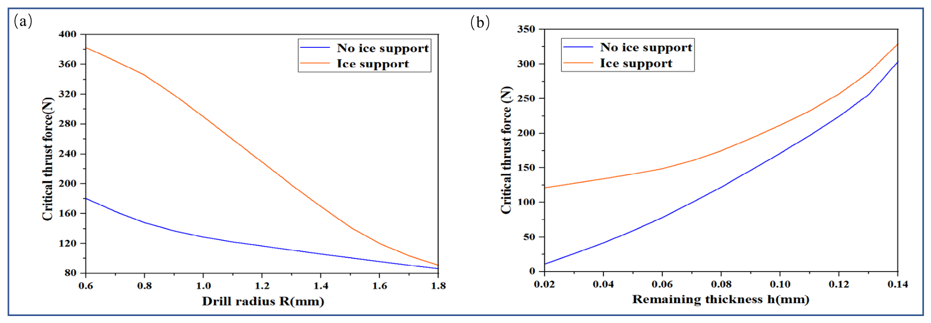
To investigate the effects of different parameters on the critical thrust force, the following parameters were used in the theoretical analysis: E = 294 GPa, GIC = 350 J/m2, ν = 0.3, h = 0.1 mm, a = R, b = 0.25 R, FC/FT = 0.4, FL/FT = 0.6, and ki = 5.7 × 10¹¹ N/m3. Figure 18 shows the variation in the critical thrust force under different drill radii. As the tool radius increases, the action range of the drilling load on the remaining layer at the hole exit is enlarged. This increases the strain energy release rate near the crack front, making the interlaminar crack easier to propagate. Therefore, the critical thrust force for hole-exit delamination decreases continuously with increasing tool radius. The analytical results suggest that the ice support may improve the bending resistance of the remaining layer and suppress crack propagation. However, the enhancement effect gradually weakens as the drill size increases. In addition, the effect of the remaining thickness at the hole exit was investigated by fixing the tool radius at R = 0.8 mm. With the increase in the remaining thickness, the deformation capacity of the remaining layer decreases significantly, resulting in a continuous increase in the critical thrust force required for crack propagation. Compared with the unsupported condition, the ice support is predicted to increase the overall stiffness of the system. As a result, a higher critical thrust force is obtained over the entire remaining-thickness range. However, the strengthening effect of the ice support gradually decreases as the remaining layer thickness increases. These results indicate that the ice support may enhance the mechanical constraint of the residual layer and increase the resistance against delamination initiation. However, because thrust force and residual-layer deformation were not experimentally measured in the present study, the calculated values could not be directly compared with experimental measurements. Therefore, the model results are used to interpret the predicted trends and the potential mechanical role of ice support rather than to provide quantitatively validated critical-thrust-force predictions.

5. Conclusions

In this study, CFRP drilling experiments were conducted under ice-supported conditions. The variations in hole-wall quality, hole-entry and hole-exit surface quality, damage morphology, tool wear, drilling temperature, and delamination characteristics were systematically investigated and compared with those obtained under conventional dry drilling conditions. Based on the experimental results, the main conclusions can be drawn as follows:
(1)
Ice-supported drilling can significantly improve the machined quality of CFRP hole walls. Compared with conventional dry drilling, defects such as cavities, fiber pull-out, and local damage on the hole wall are clearly reduced, and the structural integrity and continuity of the hole wall are improved. This improvement is considered to be associated with the thermal-regulation effect of the ice-supported condition, which reduces the temperature rise during drilling. The reduced thermal accumulation may contribute to maintaining a more stable material-removal process and reducing damage related to excessive matrix deformation.
(2)
Ice-supported drilling can effectively improve the surface quality of the hole entry and hole exit. Compared with conventional dry drilling, typical defects such as burrs, fiber tearing, and delamination at the hole entry and exit are obviously suppressed. The low-temperature condition may contribute to a more stable fiber–matrix interaction and reduce the tendency for crack initiation and propagation. Meanwhile, the ice-support structure provides effective constraint to the hole-exit region, increases the local stiffness, and weakens the bending deformation and interlaminar opening displacement caused by thrust force. The synergistic effect of low-temperature cooling and mechanical support reduces the damage sensitivity of the hole-exit region, thereby improving the surface quality of the drilled holes.
(3)
Under the investigated condition, after drilling 20 holes at 2000 r/min, the diamond-coated drill used in ice-supported drilling exhibited less severe grain blunting, surface flattening, and cutting-edge rounding than that used in conventional dry drilling. This result indicates a lower degree of apparent tool wear at the fixed hole quantity.
(4)
Ice-supported drilling can effectively suppress delamination damage during CFRP drilling. The experimental results show that, compared with conventional dry drilling, the drilling temperatures are reduced by 22.03%, 10.70%, and 11.45%, respectively, and the delamination factor is significantly decreased. The ACIP image analysis further confirms that the delamination damage areas under ice-supported drilling are smaller than those under conventional dry drilling for all process parameters, indicating that both hole-entry and hole-exit delamination are effectively suppressed.
The delamination suppression mechanism is mainly related to the combined effect of low-temperature cooling and ice support. The low-temperature environment may reduce thermal accumulation during drilling and thereby contribute to a more stable fiber–matrix interaction. Meanwhile, the ice-support structure increases the mechanical constraint of the hole-exit region and reduces deformation tendency during drilling. Meanwhile, the ice-support structure increases the supporting stiffness of the hole-exit region and suppresses interlaminar cracking and peel-up instability induced by thrust force. Therefore, ice-supported drilling weakens the damage evolution process under thermo-mechanical coupling, significantly reduces delamination damage, and improves the machining integrity of CFRP holes.

Author Contributions

B.Y.: conceptualization, data curation, writing—original draft. Y.J.: formal analysis, writing—review and editing. M.J.: investigation. W.Z.: software, methodology. B.W.: software, visualization. H.Y.: software. Z.Z.: funding acquisition, methodology, supervision, writing—review and editing. All authors have read and agreed to the published version of the manuscript.

Funding

This project is supported by the funding of the National Natural Science Foundation of China (52305510), the Natural Science Foundation of Shandong Province (ZR2023QE044), and the Graduate Innovation Foundation of Yantai University of China (Grant No. GGIFYTU2649).

Data Availability Statement

The data supporting the findings of this study are available from the corresponding author upon reasonable request.

Conflicts of Interest

The authors declare no conflict of interest.

References

  1. Ali, M.; Xiang, L.; Yue, D.; Liu, G. Assessment of Cutting Performance of Cemented Tungsten Carbide Drills in Drilling Multidirectional T700 CFRP Plate. J. Manuf. Mater. Process. 2018, 2, 43. [Google Scholar] [CrossRef] [Scilit]
  2. Hussein, R.; Sadek, A.; Elbestawi, M.A.; Attia, M.H. Chip Morphology and Delamination Characterization for Vibration-Assisted Drilling of Carbon Fiber-Reinforced Polymer. J. Manuf. Mater. Process. 2019, 3, 23. [Google Scholar] [CrossRef] [Scilit]
  3. Fernández-Pérez, J.; Domínguez-Monferrer, C.; Miguélez, M.H.; Cantero, J.L. Analysis of Tool Wear and Hole Delamination for Large-Diameter Drilling of CFRP Aircraft Fuselage Components: Identifying Performance Improvement Drivers and Optimization Opportunities. J. Manuf. Mater. Process. 2023, 7, 76. [Google Scholar] [CrossRef] [Scilit]
  4. Namlu, R.H.; Sağener, M.B.; Kılıç, Z.M.; Colak, O.; Kılıç, S.E. An Experimental Study on Ultrasonic-Assisted Drilling of CFRP Composites with Minimum Quantity Lubrication. J. Manuf. Mater. Process. 2025, 9, 276. [Google Scholar] [CrossRef] [Scilit]
  5. Jia, Z.; Bi, G.; Wang, F.; Wang, X.; Zhang, B. The Research of Machining Mechanism of Carbon Fiber-Reinforced Plastic. J. Mech. Eng. 2018, 54, 199–208. [Google Scholar] [CrossRef] [Scilit]
  6. Xu, W.; Zhang, L.C. Heat effect on the material removal in the machining of fibre-reinforced polymer composites. Int. J. Mach. Tools Manuf. 2019, 140, 1–11. [Google Scholar] [CrossRef] [Scilit]
  7. Gaugel, S.; Sripathy, P.; Haeger, A.; Meinhard, D.; Bernthaler, T.; Lissek, F.; Kaufeld, M.; Knoblauch, V.; Schneider, G. A comparative study on tool wear and laminate damage in drilling of carbon-fiber reinforced polymers (CFRP). Compos. Struct. 2016, 155, 173–183. [Google Scholar] [CrossRef] [Scilit]
  8. Davim, J.P.; Rubio, J.C.; Abrão, A.M. A novel approach based on digital image analysis to evaluate the delamination factor after drilling composite laminates. Compos. Sci. Technol. 2007, 67, 1939–1945. [Google Scholar] [CrossRef] [Scilit]
  9. Lachaud, F.; Piquet, R.; Collombet, F.; Surcin, L. Drilling of composite structures. Compos. Struct. 2001, 52, 511–516. [Google Scholar] [CrossRef] [Scilit]
  10. Fa, H. Research on Drilling Force and Drilling Heat in Micro-Hole Drilling of Carbon Fiber Composites. Master’s Thesis, Northeastern University, Shenyang, China, 2018. (In Chinese) [Google Scholar]
  11. Rawat, S.; Attia, H. Wear mechanisms and tool life management of WC–Co drills during dry high-speed drilling of woven carbon fibre composites. Wear 2009, 267, 1022–1030. [Google Scholar] [CrossRef] [Scilit]
  12. Iliescu, D.; Gehin, D.; Gutierrez, M.E.; Girot, F. Modeling and tool wear in drilling of CFRP. Int. J. Mach. Tools Manuf. 2010, 50, 204–213. [Google Scholar] [CrossRef] [Scilit]
  13. Ho-Cheng, H.; Dharan, C.K.H. Delamination during drilling in composite laminates. J. Eng. Ind. 1990, 112, 236–239. [Google Scholar] [CrossRef] [Scilit]
  14. Hocheng, H.; Tsao, C.C. The path towards delamination-free drilling of composite materials. J. Mater. Process. Technol. 2005, 167, 251–264. [Google Scholar] [CrossRef] [Scilit]
  15. König, W.; Wulf, C.; Graß, P.; Willerscheid, H. Machining of fibre reinforced plastics. CIRP Ann. 1985, 34, 537–548. [Google Scholar] [CrossRef] [Scilit]
  16. Tsao, C.C.; Hocheng, H. Effects of exit back-up on delamination in drilling composite materials using a saw drill and a core drill. Int. J. Mach. Tools Manuf. 2005, 45, 1261–1270. [Google Scholar] [CrossRef] [Scilit]
  17. Faraz, A.; Biermann, D.; Weinert, K. Cutting edge rounding: An innovative tool wear criterion in drilling CFRP composite laminates. Int. J. Mach. Tools Manuf. 2009, 49, 1185–1196. [Google Scholar] [CrossRef] [Scilit]
  18. Geier, N.; Davim, J.P.; Szalay, T. Advanced cutting tools and technologies for drilling carbon fibre reinforced polymer (CFRP) composites: A review. Compos. Part A Appl. Sci. Manuf. 2019, 125, 105552. [Google Scholar] [CrossRef] [Scilit]
  19. Abrão, A.M.; Faria, P.E.; Rubio, J.C.C.; Reis, P.; Davim, J.P. Drilling of fiber reinforced plastics: A review. J. Mater. Process. Technol. 2007, 186, 1–7. [Google Scholar] [CrossRef] [Scilit]
  20. Shokrani, A.; Dhokia, V.; Newman, S.T. Environmentally conscious machining of difficult-to-machine materials with regard to cutting fluids. Int. J. Mach. Tools Manuf. 2012, 57, 83–101. [Google Scholar] [CrossRef] [Scilit]
  21. Morkavuk, S.; Köklü, U.; Bağcı, M.; Gemi, L. Cryogenic machining of carbon fiber reinforced plastic (CFRP) composites and the effects of cryogenic treatment on tensile properties: A comparative study. Compos. Part B Eng. 2018, 147, 1–11. [Google Scholar] [CrossRef] [Scilit]
  22. Koklu, U.; Morkavuk, S. Cryogenic drilling of carbon fiber-reinforced composite (CFRP). Surf. Rev. Lett. 2019, 26, 1950060. [Google Scholar] [CrossRef] [Scilit]
  23. Liu, S.; Meng, Z.; Liang, S.; Wang, T.; Niu, H.; Luo, B.; Zhang, K. Effect of cooling temperature on machinability and hole quality in cryogenic drilling of CFRP/Ti stacks. J. Mater. Res. Technol. 2025, 36, 10383–10394. [Google Scholar] [CrossRef] [Scilit]
  24. Zou, F.; Dang, J.; Wang, X.; Zhang, H.; Sun, X.; An, Q.; Chen, M. Performance and mechanism evaluation during milling of CFRP laminates under cryogenic-based conditions. Compos. Struct. 2021, 277, 114578. [Google Scholar] [CrossRef] [Scilit]
  25. Dalle Mura, M.; Dini, G. Drilling carbon fiber reinforced plastics with pre-cooling treatment by cryogenic fluid. J. Manuf. Process. 2021, 68, 23–31. [Google Scholar] [CrossRef] [Scilit]
  26. Sahami Poor Dehghan, M.; Heidary, H. Parametric study on drilling of GFRP composite pipe produced by filament winding process in different backup condition. Compos. Struct. 2020, 234, 111661. [Google Scholar] [CrossRef] [Scilit]
  27. Hrechuk, A.; Bushlya, V. Automated detection of tool wear in machining and characterization of its shape. Wear 2023, 523, 204762. [Google Scholar] [CrossRef] [Scilit]
  28. Khashaba, U.A. A novel approach for characterization of delamination and burr areas in drilling FRP composites. Compos. Struct. 2022, 290, 115534. [Google Scholar] [CrossRef] [Scilit]
  29. Huang, G.; Lu, Q.; Li, Q.; Zhou, C.; Gu, C. Research on thermal degradation and tensile properties of carbon fiber reinforced epoxy resin composites at elevated temperatures. J. Mater. Res. Technol. 2026, 41, 2678–2690. [Google Scholar] [CrossRef] [Scilit]
  30. Tsao, C.C.; Hocheng, H.; Chen, Y.C. Delamination reduction in drilling composite materials by active backup force. CIRP Ann. 2012, 61, 91–94. [Google Scholar] [CrossRef] [Scilit]
  31. Timoshenko, S.P.; Woinowsky-Krieger, S. Theory of Plates and Shells, 2nd ed.; McGraw-Hill: New York, NY, USA, 1959. [Google Scholar]
Figure 1. Experimental equipment and characterization instruments: (a) VM25L drilling–milling machine; (b) 3D-printed mold; (c) enlarged view of the mold interior; (d) CVD diamond-coated drill; (e) experimental setup; (f) focused ion beam scanning electron microscope (FIB-SEM); and (g) metallurgical microscope.
Jmmp 10 00304 g001
Figure 2. Ice–CFRP bonding configuration: (a) overall view of the ice-supported drilling apparatus mounted on the machine tool; (b) schematic illustration of the ice–CFRP bonding structure; (c) side view of the ice-supported specimen during drilling; and (d) photograph of the ice–CFRP bonded specimen after freezing.
Jmmp 10 00304 g002
Figure 3. Schematic illustration of drilling-induced defects in CFRP laminates.
Jmmp 10 00304 g003
Figure 4. Hole-wall morphologies of CFRP under different drilling conditions: conventional dry drilling at (a) 400 r/min, (b) 1200 r/min, and (c) 2000 r/min; ice-supported drilling at (d) 400 r/min, (e) 1200 r/min, and (f) 2000 r/min.
Jmmp 10 00304 g004
Figure 5. Hole-entry morphologies of CFRP under different drilling modes: conventional dry drilling at (a) 400 r/min, (b) 1200 r/min, and (c) 2000 r/min; ice-supported drilling at (d) 400 r/min, (e) 1200 r/min, and (f) 2000 r/min.
Jmmp 10 00304 g005
Figure 6. Hole-exit morphologies of CFRP under different drilling modes: conventional dry drilling at (a) 400 r/min, (b) 1200 r/min, and (c) 2000 r/min; ice-supported drilling at (d) 400 r/min, (e) 1200 r/min, and (f) 2000 r/min.
Jmmp 10 00304 g006
Figure 7. Hole-entry damage of CFRP: (a) schematic diagram of the hole-entry damage mechanism in conventional dry drilling; (b) schematic diagram of the hole-entry damage mechanism in ice-supported drilling; (c) conventional dry drilling at 400 r/min; (d) conventional dry drilling at 1200 r/min; (e) conventional dry drilling at 2000 r/min; (f) ice-supported drilling at 400 r/min; (g) ice-supported drilling at 1200 r/min; and (h) ice-supported drilling at 2000 r/min.
Jmmp 10 00304 g007
Figure 8. Hole-exit damage of CFRP: (a) schematic diagram of the hole-exit damage mechanism in conventional dry drilling; (b) schematic diagram of the hole-exit damage mechanism in ice-supported drilling; (c) conventional dry drilling at 400 r/min; (d) conventional dry drilling at 1200 r/min; (e) conventional dry drilling at 2000 r/min; (f) ice-supported drilling at 400 r/min; (g) ice-supported drilling at 1200 r/min; and (h) ice-supported drilling at 2000 r/min.
Jmmp 10 00304 g008
Figure 9. Comparison of SEM images and wear characteristics of tool cutting edges: (a) original tool; (b) tool used in dry drilling at 2000 r/min; and (c) tool used in ice-supported drilling at 2000 r/min.
Jmmp 10 00304 g009
Figure 10. Heat-source regions and heat dissipation during different stages of ice-support-assisted CFRP drilling.
Jmmp 10 00304 g010
Figure 11. Infrared thermograms of CFRP drilling under different working conditions.
Jmmp 10 00304 g011
Figure 12. Comparison of the maximum observable temperatures extracted from infrared thermal images under conventional dry drilling and ice-supported drilling at different spindle speeds.
Jmmp 10 00304 g012
Figure 13. Determination of the delamination area using the ACIP image processing method.
Jmmp 10 00304 g013
Figure 14. ACIP images and delamination damage regions at the hole entry under different drilling conditions. Data are presented as mean ± standard deviation (n = 5).
Jmmp 10 00304 g014
Figure 15. ACIP images and delamination damage regions at the hole exit under different drilling conditions. Data are presented as mean ± standard deviation (n = 5).
Jmmp 10 00304 g015
Figure 16. Mechanism of delamination suppression by ice support during CFRP drilling.
Jmmp 10 00304 g016
Figure 17. Theoretical model of hole-exit delamination in CFRP drilling under ice-supported conditions.
Jmmp 10 00304 g017
Figure 18. Predicted trends of the critical thrust force with drill radius and remaining layer thickness based on the simplified analytical model. Predicted trends based on the simplified analytical model: (a) effect of drill radius on the critical thrust force; (b) effect of remaining layer thickness on the critical thrust force.
Jmmp 10 00304 g018
Disclaimer/Publisher’s Note: The statements, opinions and data contained in all publications are solely those of the individual author(s) and contributor(s) and not of MDPI and/or the editor(s). MDPI and/or the editor(s) disclaim responsibility for any injury to people or property resulting from any ideas, methods, instructions or products referred to in the content.