1. Introduction
Hydrodynamic cavitation is increasingly investigated for liquid processing and process intensification, particularly where controlled and reproducible treatment conditions are required [
1,
2,
3]. Its performance is highly sensitive to the operating state: variations in flow rate, pressure, temperature, apparent viscosity, dissolved gas content, and solids loading can alter cavitation inception, extent, and treatment severity, with consequences for process performance, energy use, and reproducibility [
4,
5].
These effects are especially relevant in recycling and resource-valorization applications involving waste-derived liquids, agro-industrial by-products, wet biomass, and heterogeneous suspensions. Because stream properties may vary between batches or evolve during treatment, fixed-geometry cavitation devices sized for nominal conditions may require conservative operation or repeated optimization. Reconfigurable geometry offers a means of adapting the cavitation regime while preserving the external plant interfaces.
Among the devices used to generate hydrodynamic cavitation, Venturi systems are a well-established solution [
6,
7]. They are attractive because of their simple construction, absence of rotating parts, and compatibility with in-line integration. In industrial practice, however, a conventional Venturi is usually manufactured with a fixed internal geometry and sized for a nominal set of operating conditions [
8,
9,
10].
Fixed-geometry Venturi devices may perform adequately near their nominal design point, but their operating regime can shift when process conditions or treatment objectives change. In variable or sequential processes, maintaining a target cavitation condition may therefore require adjustments in flow rate or pressure, repeated optimization, or acceptance of suboptimal operation [
9,
10,
11]. Variable-area and adjustable Venturi devices demonstrate that internal geometry can instead be used as an operating degree of freedom for regulating pressure drop, flow behavior, and cavitation inception [
12,
13,
14,
15].
On this basis, the Dynamic Circular Venturi Adaptive (DCVA) is introduced as a family of circular Venturi devices with reconfigurable internal geometry [
16]. The external body and pipeline interfaces remain fixed, while the throat region and adjacent transition sections can be adjusted so that geometry becomes an operating variable. The framework is related to, but distinct from, the Dynamic Venturi Reuleaux Actuated (DVRA) concept [
17]. Whereas the DVRA combines a non-circular Reuleaux-section throat with boundary-imposed swirl and adjustment of the effective hydraulic area, the DCVA retains an axisymmetric circular geometry, introduces no swirl-forcing mechanism, and describes profile reconfiguration through the equivalent throat diameter or area, throat-region length, and inlet and outlet transition angles. The DCVA should therefore be regarded as a distinct axisymmetric reconfiguration framework rather than as a circular variant of the DVRA.
The DCVA can serve either as a reconfigurable development platform or as an adaptive in-line device. In the first role, different combinations of geometry and operating conditions can be explored to identify candidate configurations or operating windows for a given matrix or treatment objective. In the second, the internal profile can be adjusted during operation to accommodate changes in fluid properties, hydraulic conditions, or sequential processing requirements.
The framework defines equivalent geometric parameters, an admissible design space, plant-measurable operating indicators, and two representative architectures. DCVA-S uses a single geometric degree of freedom associated primarily with throat opening, whereas DCVA-M enables multiparametric profile reconfiguration through axially distributed actuation. A numerical workflow based on automated axisymmetric finite-element CFD is also used to connect parametric geometry generation, meshing, flow simulation, post-processing, and iterative throat updating for cavitation-inception sizing. This workflow supports configuration selection and commissioning-map development.
2. DCVA Framework
The DCVA is conceived as an in-line hydrodynamic cavitation module with fixed external dimensions and reconfigurable internal geometry. The inlet and outlet connections remain unchanged, whereas the throat region and adjacent transition sections can be adjusted to modify the cavitation regime in response to operating conditions or process requirements. Its geometric state is described through equivalent throat diameter, throat-region length, and inlet and outlet transition angles, together with bounded control variables and plant-measurable hydraulic quantities.
2.1. Geometry and Control
Two limiting throat diameters define the available geometric stroke. The minimum throat diameter,
, corresponds to the most constricted admissible configuration, whereas the maximum throat diameter,
, corresponds to the most open configuration. The equivalent throat diameter during operation,
, therefore satisfies:
The interval represents the available geometric stroke. The ratio quantifies the maximum relative opening achievable for a given external envelope. The minimum value is set by process requirements, whereas is limited by design constraints, including mechanical integrity, materials, and reliability, as well as by operating conditions.
To describe and control the throat opening, a dimensionless control variable is introduced:
The value
corresponds to the minimum-throat configuration,
, whereas
corresponds to the maximum-throat configuration,
. Equation (2) yields the direct control-to-geometry relation:
The variable represents a bounded supervisory command rather than a complete actuator state. Its admissible variation is limited by actuator stroke and response, backlash, hysteresis, liner stiffness and strain, sealing behavior, and pressure loading. Practical operation therefore requires calibrated command-to-geometry mapping, configuration-dependent safety limits, and command-rate constraints. Actuator dynamics, closed-loop stability, liner deformation, and cyclic durability remain device-specific validation requirements.
The main symbols used in the DCVA framework and in the two representative architectures are summarized in
Table 1.
In addition to , the internal profile is summarized by the equivalent throat-region length, and the equivalent transition angles, and . The quantity is defined as the axial extent over which the local internal diameter remains within a prescribed tolerance of the minimum profile diameter. The angles and represent effective slopes of the converging and diverging sections, respectively, and may be obtained from the corresponding profile segments by geometric reconstruction or best-fit linear approximation. The diameter tolerance and fitting intervals must be reported for each implementation. Depending on the architecture, these quantities may be fixed, directly actuated, or kinematically coupled.
2.2. Hydrodynamics and Design Space
The cavitation regime can be characterized by a throat-based cavitation number [
18,
19]. Let
denote the mean static pressure at the throat,
the mean velocity at the throat,
the vapor pressure at temperature
, and
the fluid density. The following definition is adopted:
All pressures in Equation (4) are absolute and referenced to vacuum. The method used to determine , including the sampling location or averaging region, must be reported because local minima, wall-adjacent values, centerline values, and section-averaged pressures need not coincide in a cavitating flow. Under fixed upstream and downstream conditions, variation of modifies the throat velocity and pressure field, thereby shifting the operating state represented by .
The admissible geometric configurations are represented by the design space:
The bounds in are implementation-specific rather than universal. They are defined by the intended process duty, device scale, operating-pressure range, fluid properties, material compatibility, actuator stroke, allowable liner deformation, sealing requirements, and durability constraints. The architecture and kinematic mechanism determine the reachable subset of , because some parameters may be directly actuated whereas others remain fixed or vary through geometric coupling. For preliminary comparison across scales, the design bounds may also be expressed through normalized quantities such as , , and .
2.3. Measured Signals and Indicator
In a process-plant context, a direct measurement of the throat pressure may not be available. An operational indicator is therefore introduced and computed from quantities typically measured in process plants, namely the inlet pressure , the outlet pressure , the volumetric flow rate , and the temperature , from which is obtained. The dependence on geometry is captured through the equivalent throat diameter , computed from Equation (3) in the single-parameter case or derived from the equivalent profile in the multiparametric case.
A continuity-based estimate of the mean throat velocity,
, is adopted:
Using
and plant-measurable quantities, the following operational indicator is defined:
In the following, is used as an operational proxy for the cavitation regime, since it is computed from and the equivalent throat diameter through the velocity estimate . Consequently, does not necessarily coincide with the local cavitation number in Equation (4), which would require a direct measurement of the throat pressure . Accordingly, is introduced as a design-oriented proxy for consistent configuration selection and reporting, rather than as a direct substitute for the local cavitation number.
This distinction is particularly important in unsteady cavitating flows, where cavitation inception, shedding, local pressure minima, vapor-volume evolution, and pressure fluctuations cannot be represented by mean throat quantities alone. Studies on confined throttling geometries have shown that cavitation inception and pressure behavior are governed by local flow acceleration and near-wall pressure drops. This supports the use of
as a commissioning and reporting proxy, rather than as a validated cavitation-intensity measure [
20].
A first-order deviation can be expressed by writing , where accounts for inlet-to-throat losses. Under this definition, ; hence the deviation is governed by and is quantified during commissioning for the specific duty.
Related studies highlight practical limits when using simplified indicators to represent cavitation intensity [
21]. When needed, non-idealities can be addressed through calibrated flow-coefficient information for variable-area cavitating Venturi devices [
22]. The indicator
is employed to build commissioning maps and to compare configurations in a repeatable manner under a consistent estimation criterion [
23,
24,
25].
The reliability of is therefore configuration and duty-dependent. Variations in throat opening, transition angles, throat-region length, surface deformation, and flow regime may modify the inlet-to-throat pressure loss and the relation between the estimated velocity and the actual local throat flow. For this reason, should be interpreted as a repeatable operational indicator for configuration selection and process supervision, rather than as a direct measurement of local cavitation intensity. In practical implementations, its use for in-line control should be supported by commissioning maps and, where required, by independent cavitation-related measurements or process-response indicators.
The outlet pressure is used to monitor operating conditions and, when needed, to verify plant constraints through the pressure drop .
3. DCVA-S: Single-Parameter
The DCVA-S implements a single directly actuated geometric degree of freedom associated with throat opening. Synchronously driven radial actuators vary the equivalent throat diameter while the inlet and outlet interfaces remain fixed.
3.1. Single-Parameter Architecture
The architecture comprises three functional subassemblies: an external actuation system, a circumferential kinematic cage, and an elastomeric liner forming the continuous wetted surface. The actuators impose a coordinated radial displacement represented by the control variable . The kinematic cage transfers this displacement through repeated circumferential modules to the retaining rings supporting the liner. The rings are connected to the stationary cylinder bodies rather than to the moving rods, thereby limiting shear and lateral loading during reconfiguration. The liner deforms in response to cage motion while maintaining continuity of the internal flow surface.
Liner material selection and sizing are application-dependent and are therefore not prescribed at this design-framework level. The liner can be parameterized through thickness and effective stiffness, while throat-diameter variation can be expressed as a function of liner radial deformation. These quantities must be specified according to the selected device scale, operating pressure range, material compatibility, and process duty [
26,
27,
28,
29].
The elastomeric liner should therefore be regarded as an implementation-specific deformable wetted interface, not as a universal material solution. Long-term operation requires assessment of cavitation-erosion resistance, cyclic fatigue, hysteresis, sealing reliability, chemical compatibility, and allowable deformation under repeated reconfiguration. These aspects define device-level validation requirements and must be assessed during prototype development and experimental benchmarking.
The throat section has a constant axial length,
, set by design and interpreted as the equivalent length of the throat region. During operation, the equivalent throat diameter
varies, whereas
is kept constant by the kinematic constraints of the single-parameter architecture. The DCVA-S representations in
Figure 1,
Figure 2 and
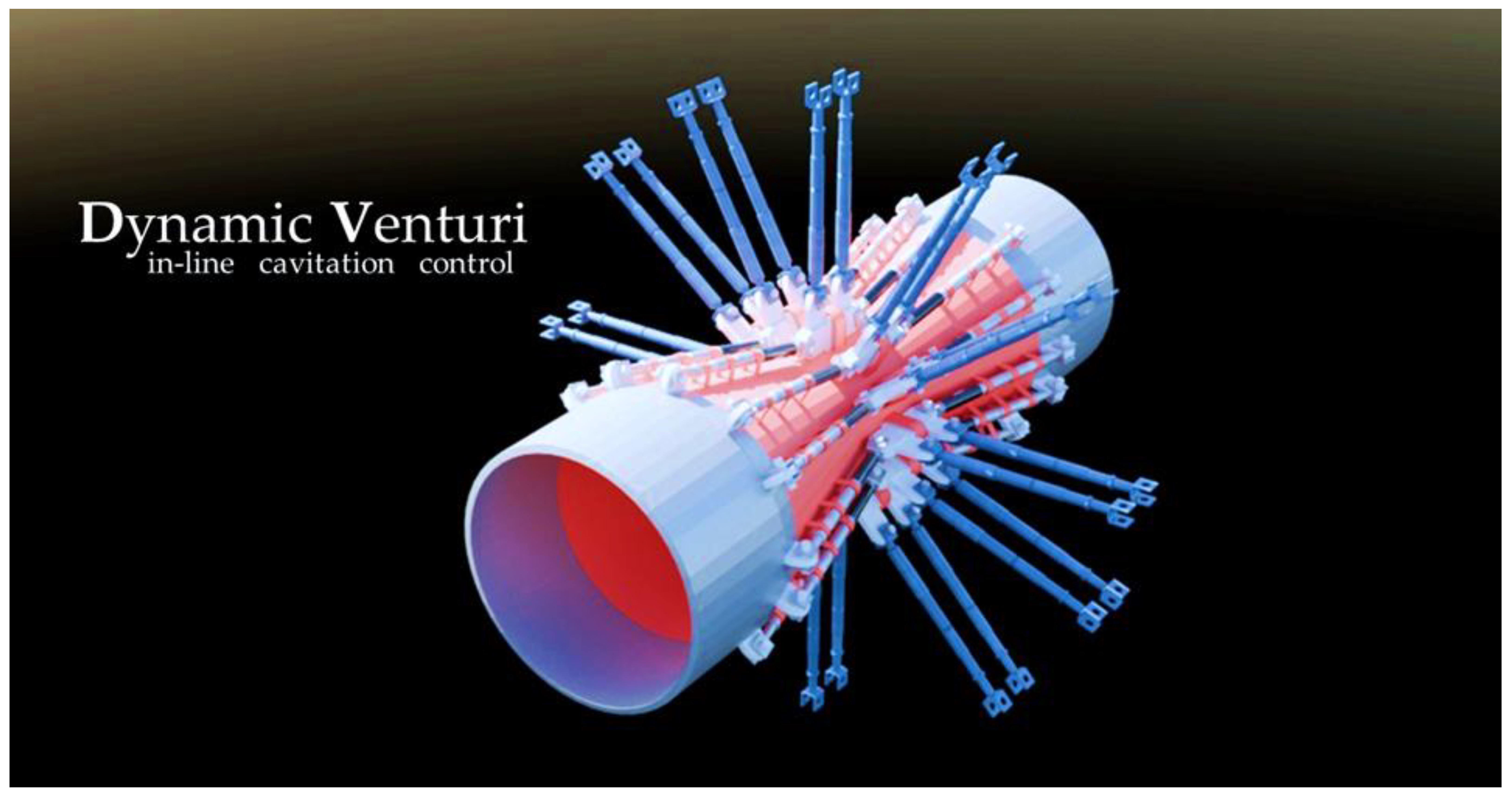
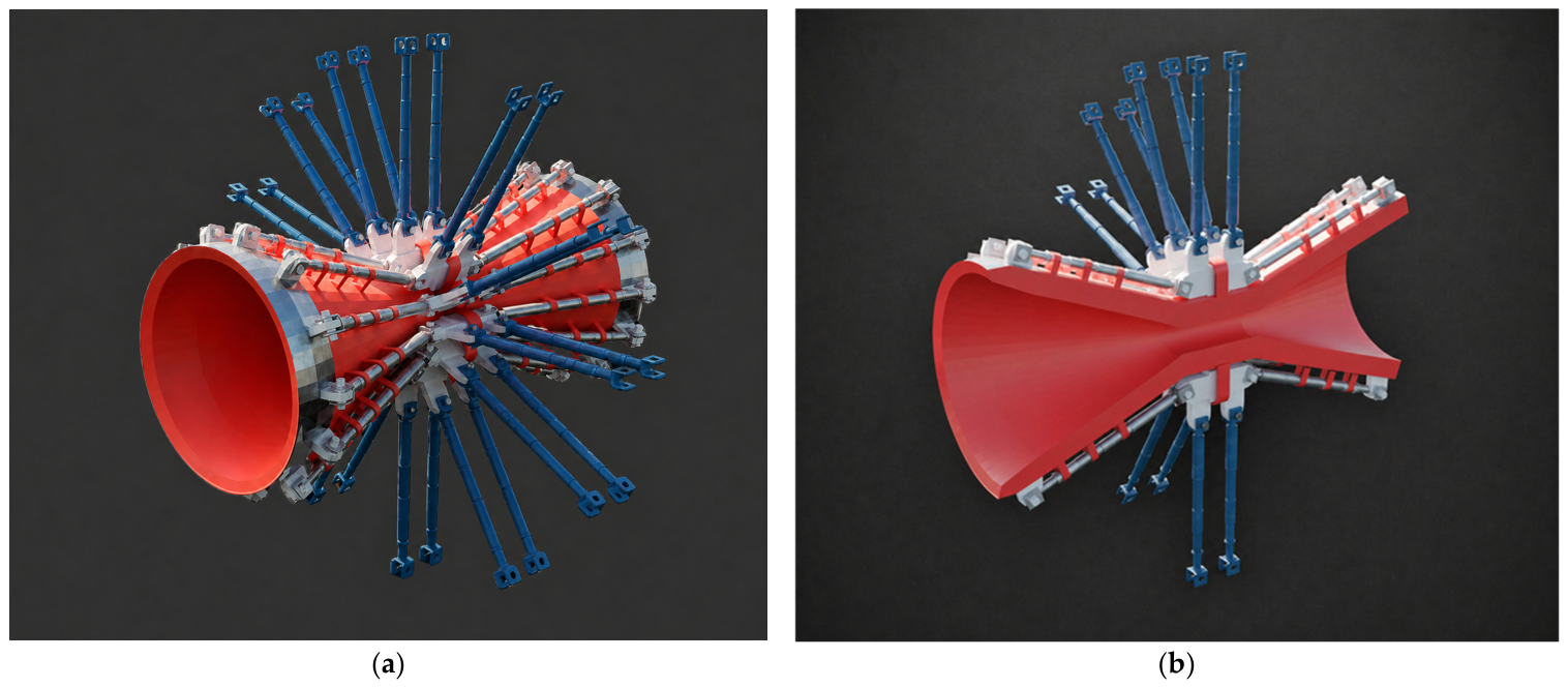
Figure 3 are functional schematics rather than dimensioned engineering drawings; absolute dimensions, liner material properties, actuator specifications, and sealing assumptions are therefore not prescribed at this framework stage and must be defined for the selected prototype scale and process duty. The resulting DCVA-S architecture and the arrangement of its principal functional components are shown in
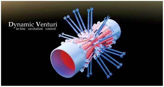
Figure 1.
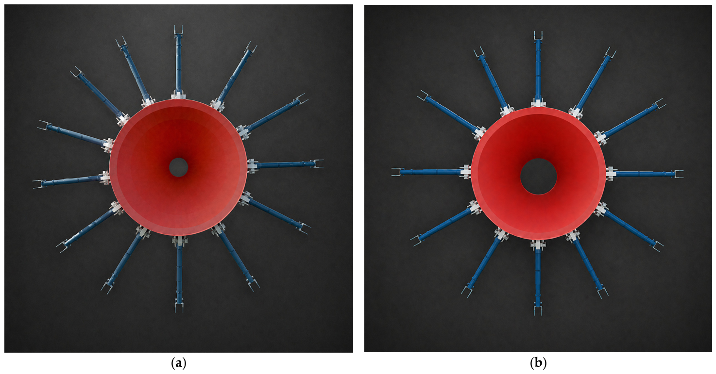
The two limiting throat configurations of the DCVA-S are shown in
Figure 2.
Figure 2.
Front view of the DCVA-S in the two limiting configurations: (a) minimum internal throat section, ; (b) maximum internal throat section, .
Figure 2.
Front view of the DCVA-S in the two limiting configurations: (a) minimum internal throat section, ; (b) maximum internal throat section, .
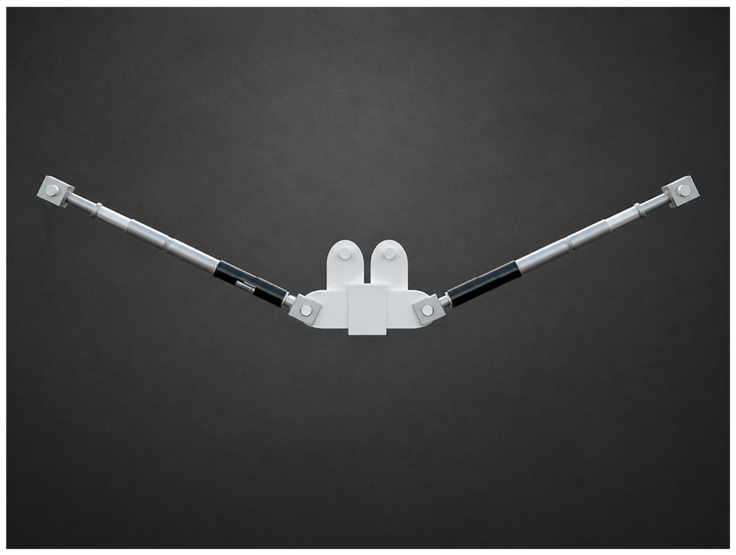
To clarify the modular nature of the kinematic cage,
Figure 3 shows the elementary module repeated
times along the circumference.
Let denote the number of elementary cage modules distributed around the circumference. Increasing improves the uniformity of the circumferential constraint and, consequently, the repeatability of the resulting internal geometry. Higher values of reduce local deformations between adjacent constraint points and distribute liner stresses more uniformly, at the expense of increased mechanical complexity and more demanding assembly and actuation.
In practical implementations, the selection of should be treated as an application-specific design trade-off. Larger pipe diameters, higher pressure drops, stiffer liners, stricter requirements on throat circularity, and frequent reconfiguration cycles may require higher circumferential modularity to reduce local liner distortion and stress concentration. Conversely, smaller devices, moderate deformation ranges, or applications with less stringent geometric-uniformity requirements may favor lower values in order to reduce mechanical complexity, cost, and maintenance requirements.
As a preliminary design guideline, should be selected so that the circumferential spacing between adjacent constraint modules, approximately at the throat, remains compatible with the allowable departure from circularity, liner stiffness, imposed radial deformation, pressure loading, and cyclic durability requirements. This criterion is not a universal sizing rule, but a practical design check to be refined according to the selected liner material, pressure range, actuation stroke, and durability requirements.
3.2. Operation and Kinematics
The reconfiguration of the DCVA-S is described by a single dimensionless parameter
, defined within the general framework introduced in
Section 2. The control input
determines the equivalent throat diameter
through the command-to-geometry relation given in Equation (3).
Consistent with
Figure 1,
Figure 2 and
Figure 3, the external actuators shown in blue impose a coordinated displacement of the kinematic cage. The cage modules transfer this displacement to the retaining rings, while the elastomeric liner shown in red deforms and maintains a continuous internal wetted surface. As a result, the equivalent throat diameter
varies between
and
, as shown in
Figure 1 and
Figure 2, while the inlet and outlet piping interfaces remain unchanged.
Figure 3.
Elementary module of the DCVA-S kinematic cage. Circumferential repetition of modules forms the complete cage.
Figure 3.
Elementary module of the DCVA-S kinematic cage. Circumferential repetition of modules forms the complete cage.
In the DCVA-S architecture, the only directly actuated geometric degree of freedom is the equivalent throat diameter . The equivalent length of the throat region, , is fixed by design. By contrast, the effective inlet and outlet angles, and , may vary as induced geometric quantities coupled to . They are therefore determined by kinematics rather than controlled independently.
For an illustrative piecewise-linear representation, let
and
denote the fixed internal diameters at the inlet and outlet connections, respectively, and let
and
denote the corresponding fixed axial transition lengths. Defining
and
as half-angles measured relative to the Venturi axis, the kinematic coupling can be expressed as
and
Since , the corresponding angular ranges are bounded by the values obtained at and . These relations provide an explicit geometric example for verifying whether the induced angles remain within the admissible design space. For the curved liner profile, however, and should be determined from CAD-based profile reconstruction or best-fit geometric approximation rather than assumed to follow the idealized piecewise-linear relations exactly.
For an axisymmetric circular profile with a uniform throat section, the equivalent throat diameter coincides with the physical minimum internal diameter used in the CAD and CFD geometry; therefore, . For non-uniform DCVA-M profiles, remains an equivalent quantity defined from the minimum internal diameter of the reconstructed profile.
Formally, the DCVA-S explores a one-dimensional subset of the design space
, parameterized by the equivalent throat diameter:
In Equation (10), denotes the design value of the equivalent throat-region length, whereas and represent the effective inlet and outlet angles induced by the kinematics as varies. These functions can be determined through geometric reconstruction, CAD-based calibration, or experimental measurement, depending on the development stage and on the available characterization method.
3.3. Commissioning and Operation
The DCVA-S can be operated through a commissioning map that links the control input
to the internal geometry and to the target cavitation range [
23,
24,
25]. Such a map can be constructed by sampling a discrete set of
values and determining the equivalent throat diameter
through the command-to-geometry relation in Equation (3), with direct geometric verification when required. In the same step, the coupled variation of the effective inlet and outlet angles imposed by the kinematics is characterized and checked against the admissible design limits.
Using the measured quantities , , , and , together with Equations (6) and (7), the operational proxy can then be estimated and represented as a – curve or lookup table. This map provides a repeatable basis for selecting the throat-opening command under a consistent estimation criterion.
The commissioning map can be obtained through a calibration sequence combining geometric verification of
, measurement of plant variables, and independent cavitation-related checks such as pressure fluctuations, acoustic emission, optical visualization, or process-response indicators. CFD analysis can also support the estimation of inlet-to-throat losses and the construction of configuration maps. The numerical workflow described in
Section 5 provides a physics-based route for identifying throat configurations associated with cavitation inception under prescribed hydraulic conditions.
The operational proxy is computed from , , and the continuity-based estimate of the throat velocity . It therefore does not represent a direct measurement of the local cavitation number at the throat. During operation, is selected as a process-control variable to approach the desired cavitation range, for example within a target interval of , while satisfying practical constraints such as maximum allowable pressure drop, actuator stroke, liner deformation limits, and mechanical safety bounds.
4. DCVA-M: Multiparametric
The DCVA-M configuration extends the dynamic circular Venturi concept by introducing multiparametric reconfiguration of the internal profile. The wetted surface is not reconfigured through a single global actuation variable, but through axial stations distributed along the converging section, throat region, and diverging section. This architecture generates a family of internal profiles that vary along the axis and enables modulation of the equivalent throat diameter, transition shapes, and throat-region extent, while preserving the inlet and outlet piping interfaces.
4.1. Multiparametric Architecture
The DCVA-M retains an outer cartridge with fixed inlet and outlet connection diameters. Reconfiguration of the internal wetted surface is achieved through axially distributed actuation stations along the Venturi axis. Each station locally sets the radial position of the liner and, through coordinated actuation, contributes to the generation of an admissible internal profile. The external connections remain unchanged, whereas the internal geometry becomes a function of the station commands and can be summarized by the equivalent parameters , , , and .
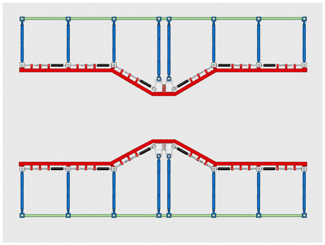
In the schematic representation, the outer cartridge, liner, actuators, and kinematic components are distinguished by color coding. The outer cartridge is shown in green, the liner in red, the actuators in blue, and the kinematic components in white/gray.
The number and spacing of the actuation stations determine the achievable profile resolution. Actuation strategy, synchronization, position feedback, sealing arrangement, and structural implementation are device-dependent.
A possible implementation may consist of axially distributed retaining rings coupled to synchronized radial linear actuators, with position feedback used to define repeatable admissible profiles. The actuator type, drive mechanism, sealing layout, liner material, and detailed structural design depend on device scale, pressure range, material compatibility, and process duty. The role of the DCVA-M framework is to define the equivalent profile parameters and the admissible operating logic required for subsequent mechanical design, prototype realization, and device-level validation. A representative DCVA-M architecture with axially distributed actuation is shown in
Figure 4.
4.2. Operation and Parameters
In the DCVA-M, reconfiguration is described by a set of dimensionless control inputs associated with the axial actuation stations. The axial layout is defined by the station locations
along the Venturi axis, with
. The input of station
is denoted by
, with
. The admissible set of control inputs is defined as
In the following, is assumed.
The representative schematic in
Figure 4 contains
axial station locations. Their spacing is nonuniform and illustrative; no absolute station spacing is prescribed because the schematic is not dimensioned. At each location
, the command
sets the local radial position of the liner, and the coordinated station commands define the resulting internal profile. Equivalent geometric parameters are introduced to summarize the family of profiles achievable as
varies. The equivalent throat diameter
is defined as the minimum value of the internal profile. The equivalent length of the throat region
is defined as the axial extent of the portion close to the minimum according to an operational threshold. The effective inlet and outlet angles,
and
, are determined as equivalent slopes of the converging and diverging sections through geometric or experimental calibration.
These mappings are not intended as universal analytical laws, but as architecture-specific geometry-to-parameter relations. For a given implementation, they can be obtained from the kinematic layout of the actuation stations, CAD-based profile reconstruction, direct geometric measurement, or calibration tests. Their role in the present framework is to define how each admissible command vector is translated into equivalent geometric parameters before hydrodynamic characterization or process operation.
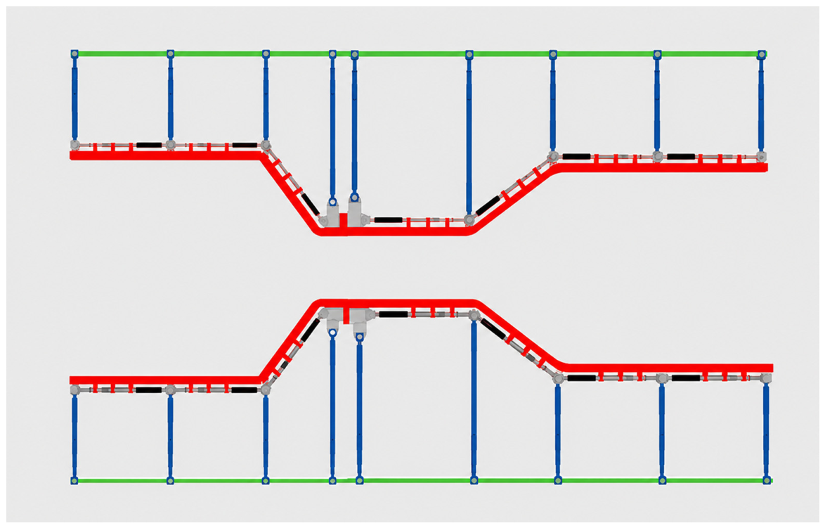
Schematic examples of internal profiles obtained by varying the station control inputs are shown in
Figure 5. The figure highlights that multiparametric reconfiguration enables variation not only of
, but also of the transition shapes and the extent of the throat region, thereby generating different combinations of
,
,
, and
within the design constraints.
4.3. Design Space
The DCVA-M realizes only a subset of the admissible geometries in the design space
defined in Equation (5), since the kinematics and actuator limits impose constraints on the reachable configurations. In compact form, the set of achievable configurations is described as:
The functions , , , and describe the effect of multiparametric reconfiguration enforced by the axially distributed actuation stations. These functions are determined by the device kinematics and by the selected calibration or characterization procedure. The equivalent parameters are generally coupled and must remain within mechanical, hydraulic, and geometric limits.
This coupling implies that not every combination of equivalent throat diameter, throat-region length, and inlet/outlet transition angles within is physically reachable by the DCVA-M architecture. The accessible design space is restricted to configurations satisfying actuator-stroke limits, liner-strain limits, geometric-continuity requirements, sealing constraints, and kinematic compatibility between adjacent axial stations.
Axial smoothness of the control inputs is therefore important to prevent overly segmented profiles and localized liner deformation. In practical control schemes, smoothness can be enforced by constraining the first difference between neighboring station inputs, and the command rate of each station, , within implementation-specific admissible limits. Alternatively, operation may be restricted to pre-defined admissible profiles satisfying prescribed geometric-continuity and linear-deformation criteria. This approach reduces the risk of localized deformation while preserving the multiparametric flexibility of the architecture.
4.4. Calibration and Operation
A practical operating strategy is to build a catalog of admissible profiles obtained from geometric reconstruction, CAD-based calibration, numerical characterization, or experimental calibration when available. For each configuration, a corresponding value of the operational proxy can be estimated using Equations (6) and (7), based on the equivalent throat diameter of the selected profile and the available plant measurements. In the multiparametric case as well, is used as an operational proxy based on , , and . It does not replace direct determination of the local cavitation number or independent cavitation-related diagnostics at the throat.
During operation, the operator or supervisory system selects a configuration
from the admissible profile catalog to approach the desired cavitation range while satisfying plant constraints and mechanical reconfiguration limits [
25]. These constraints include allowable pressure drop, actuator stroke, liner deformation, geometric smoothness, sealing reliability, and configuration-dependent safety bounds.
5. Numerical Demonstration of the Parametric Venturi Design Workflow
A numerical demonstration is presented to illustrate the transition from the DCVA design framework to a quantitatively defined inverse CFD-assisted hydraulic-sizing procedure capable of automatically identifying the throat geometry associated with a prescribed cavitation-inception condition. The computationally efficient steady RANS pressure-field calculation is used for preliminary DCVA configuration rather than for validation of fully developed cavitating flow. The resulting geometry represents a candidate design and may serve as the starting point for higher-fidelity transient, multiphase, and three-dimensional CFD analyses and for experimental validation, where required by the specific application.
5.1. Objective and Scope of the Numerical Demonstration
The numerical demonstration focuses on the parametric hydraulic-design workflow used to identify the Venturi throat configuration associated with cavitation inception under prescribed operating conditions. The objective is to verify whether a parameterized circular Venturi geometry can be automatically updated until the computed throat pressure satisfies a prescribed cavitation-inception condition.
This objective is consistent with the DCVA framework. In DCVA-S, throat opening is the directly actuated geometric variable. In DCVA-M, the equivalent throat diameter is one of the parameters derived from the reconfigurable internal profile. In both cases, the ability to determine the throat geometry required to approach a target cavitation condition is a necessary step for admissible-configuration selection, numerical characterization, and future supervisory control.
Cavitation inception is treated as the hydraulic condition in which the static pressure in the throat region reaches the prescribed cavitation-inception pressure for the selected fluid and operating state. The operating behavior of a Venturi tube, and the onset of cavitation in particular, depend strongly on the hydraulic boundary conditions imposed by the surrounding circuit. For a prescribed process flow rate, the available inlet pressure and the pressure losses in the hydraulic circuit determine the pressure drop that can be converted into local acceleration through the throat. The numerical workflow therefore solves an inverse hydraulic-design problem: for a given flow rate, working fluid, inlet/outlet diameter, and fixed transition geometry, the throat diameter is iteratively adjusted until the computed throat pressure converges toward the selected cavitation-inception target.
5.2. Parametric Geometry and Operating Case
A circular Venturi geometry was selected for the numerical demonstration. The computational geometry was parameterized using the same class of geometric quantities introduced in the DCVA framework, namely the converging-section angle, diffuser angle, throat radius, inlet and outlet radius, and throat-region length. For the demonstration case, the inlet and outlet diameters were kept fixed, whereas the throat radius was treated as the free design variable. Under these constraints, the lengths of the converging and diverging sections were determined by the prescribed transition angles.
The diffuser half-angle was fixed at 3.5°, corresponding to a total diffuser angle of 7°. This value was selected to promote gradual pressure recovery and to limit the risk of boundary-layer separation, since diffuser geometry strongly affects pressure recovery and irreversible hydraulic losses downstream of the throat. The converging-section half-angle was fixed at 20°, corresponding to a total converging angle of 40°, in order to limit the overall axial length of the device while preserving a sufficiently progressive acceleration toward the throat. The throat-region length was set to , providing a finite interaction length for the accelerated low-pressure flow. Both the inlet and outlet diameters were set to . Under these geometric constraints, variation of the throat radius directly controls the degree of flow acceleration and the pressure reduction in the throat region. Alternative parameterization strategies could also be implemented, for example, by prescribing the axial lengths of the converging and diffuser sections and allowing the inlet or outlet dimensions to vary within installation constraints.
Water at 20 °C was used as the working fluid. The density was set to , the dynamic viscosity to , and the vapor pressure to . A mass flow rate of was prescribed. This operating condition was deliberately selected as a conservative and demanding hydraulic case because it produces high velocities, elevated Reynolds numbers, and large pressure gradients within the Venturi. The corresponding inlet Reynolds number was approximately , indicating turbulent inlet flow.
The demonstration case is defined by the geometric, fluid, and operating quantities reported in
Table 2. The table separates prescribed quantities from derived inlet-flow quantities, so that the hydraulic severity of the selected case is explicit before introducing the numerical model.
The inlet-flow quantities reported in
Table 2 were obtained from the prescribed mass flow rate and inlet diameter. The volumetric flow rate, inlet cross-sectional area, section-averaged inlet velocity, and inlet Reynolds number were calculated as
where
is the volumetric flow rate,
is the inlet cross-sectional area,
is the inlet diameter,
is the section-averaged inlet velocity, and
is the inlet Reynolds number. For the selected operating condition, these expressions give
,
,
, and
. The inlet flow can therefore be considered fully turbulent, and even higher local Reynolds numbers are expected in the throat region because of the progressive reduction of the flow area.
A preliminary analytical estimate of the throat diameter was obtained from Bernoulli’s equation and continuity, neglecting viscous losses, local losses, and elevation changes. Cavitation inception was assumed to occur when the static pressure in the throat reaches the vapor-pressure level of water at the selected temperature. Under these assumptions, the Bernoulli throat-velocity estimate and the corresponding throat-diameter estimate are given by
where
is the Bernoulli throat-velocity estimate,
is the section-averaged inlet velocity,
is the reference inlet pressure used for the analytical estimate,
is the vapor pressure,
is the fluid density,
is the mass flow rate, and
is the Bernoulli throat-diameter estimate.
For the values reported in
Table 2, the preliminary analytical calculation gives
and
.
where
is the ideal throat Reynolds number associated with the Bernoulli throat-velocity and throat-diameter estimates. This value confirms that turbulent conditions are expected not only at the inlet but also in the throat region.
The analytical estimate provides only an initial design value, because viscous dissipation, local hydraulic losses, and pressure-recovery effects are not included. The final throat diameter associated with cavitation inception was therefore determined through the iterative finite-element CFD workflow described in the following sections.
5.3. Numerical Model and Mesh Verification
The numerical model was implemented through an open-source computational workflow based on Salome-Meca (v9.13.0; EDF R&D, Clamart, France) for parametric CAD generation and mesh construction, and Elmer FEM (v26.1; CSC—IT Center for Science, Espoo, Finland) for finite-element flow simulation. The Shaper module was used to generate the parameterized Venturi geometry, while the Mesh module was used to discretize the computational domain. The finite-element simulations were then performed in Elmer FEM.
The flow domain was represented as a two-dimensional axisymmetric section corresponding to one half of the longitudinal cross-section of the Venturi. This formulation reduces computational costs while preserving the axisymmetric character of the circular geometry considered in the demonstration case. The simulations were performed as steady-state incompressible turbulent-flow calculations.
A standard Reynolds-averaged k-ε turbulence model was adopted, while Reichardt wall functions, as implemented in Elmer, were used for the near-wall treatment [
30]. This choice was consistent with the high-Reynolds-number internal-flow conditions of the demonstration case and provided a computationally efficient model for the iterative workflow. The diffuser half-angle was selected to promote gradual pressure recovery and to limit extensive flow separation, thereby reducing one of the main conditions under which the standard
-
model may become less reliable.
Because the objective was the preliminary identification of the throat geometry associated with a prescribed inception-pressure threshold, the steady single-phase RANS model was used to resolve the mean hydraulic pressure field rather than the subsequent vapor dynamics. This modeling level is adequate for the stated inverse-sizing demonstration under a consistent set of assumptions, but the resulting throat diameter remains model-dependent. Sensitivity to alternative turbulence closures or boundary-condition formulations, and comparison with an external Venturi benchmark, were not performed; consequently, the converged value of 10.56 mm is conditional on the adopted model and boundary conditions and should not be interpreted as a benchmark-validated or model-independent prediction.
The physical pressure criterion is independent of the pressure reference provided that absolute and gauge pressures are converted consistently; inconsistent reference conventions would instead alter the numerical target and the resulting diameter. Transient multiphase and three-dimensional analyses remain necessary for prediction of vapor-volume evolution, cloud shedding, collapse intensity, erosion-related quantities, and unsteady cavitation dynamics.
A fully developed turbulent velocity profile was prescribed at the inlet using a one-seventh power-law distribution,
where
is the local axial inlet velocity at radial coordinate,
and
is the maximum axial inlet velocity, and
is the inlet radius.
The value of was selected so that the section-averaged inlet velocity matched the prescribed mass flow rate. In the present case, and . The radial velocity component at the inlet was set to zero. A zero-gauge-pressure condition was prescribed at the outlet, while no-slip conditions were imposed at the solid walls. An axisymmetric boundary condition was applied along the centerline.
The inlet turbulence quantities were estimated from a turbulence intensity of
and a turbulence length scale equal to
. The turbulent kinetic energy and turbulent dissipation rate were calculated as
where
is the turbulent kinetic energy,
is the turbulent dissipation rate,
is the turbulence intensity,
is the section-averaged inlet velocity,
is the turbulence length scale, and
is the standard
-
model constant [
31]. The corresponding inlet values were
and
. The computational domain was initialized using the same one-seventh power-law velocity profile prescribed at the inlet, while the initial radial velocity was set to zero.
The numerical configuration used for the demonstration case is summarized in
Table 3. The table reports the computational workflow, modeling assumptions, boundary conditions, turbulence inputs, mesh settings, and computational cost adopted in the finite-element simulations.
The computational domain was discretized using a structured quadrilateral mesh with boundary-layer refinement. A mesh-sensitivity study was carried out to identify a mesh resolution capable of providing stable throat-pressure predictions while maintaining acceptable computational cost.
The static pressure at the throat centerline was adopted as the convergence variable because it provides a stable, repeatable, and numerically robust scalar quantity for the automated iterative sizing procedure. This choice should not be interpreted as assuming that cavitation necessarily initiates along the centerline; rather, it defines a design-oriented criterion for the inverse hydraulic sizing workflow. Predicting the exact spatial location of cavitation inception would require dedicated multiphase cavitation modeling and experimental validation and is beyond the scope of the present analysis.
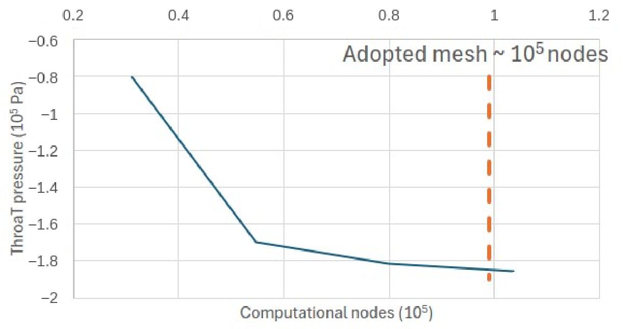
The mesh-sensitivity analysis was performed using a throat diameter of 9 mm, corresponding to a demanding hydraulic configuration with high velocity and large pressure gradients. As shown in
Figure 6, the predicted throat pressure progressively stabilized as the mesh was refined. The results for the two finest meshes and the criterion adopted for the final mesh selection are summarized in
Table 4. Increasing the mesh resolution from 79,974 to 103,670 computational nodes changed the predicted throat-centerline static pressure from −181.3 to −185.5 kPa gauge, corresponding to a relative difference of 2.3%. The mesh containing 103,670 computational nodes was therefore adopted as a compromise between throat-pressure stability, pressure-field resolution, and computational cost.
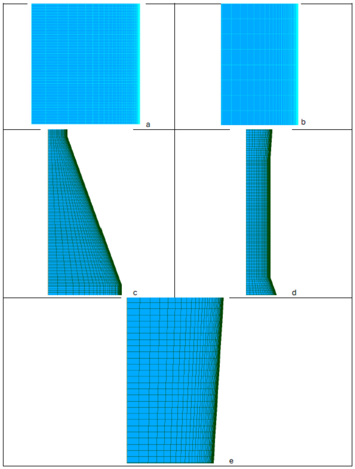
Representative details of the adopted mesh are shown in
Figure 7. The panels illustrate the inlet-region mesh, the converging section, the throat region, and the diverging section. Mesh refinement was concentrated near the wall and in the regions where velocity gradients and pressure variations are most relevant to the prediction of cavitation inception.
The adopted discretization was used for all subsequent simulations in the iterative workflow. This choice provided a compromise between numerical stability, pressure-field resolution in the throat region, and computational efficiency during repeated geometry regeneration and solution.
5.4. Automated Cavitation-Inception Workflow
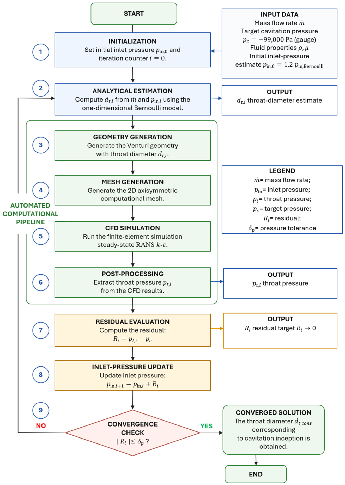
The throat diameter associated with cavitation inception was determined through an automated iterative workflow. The procedure couples analytical initialization, parametric geometry generation, mesh generation, finite-element CFD simulation, post-processing, residual evaluation, and iterative updating. Each iteration generates a candidate Venturi geometry, evaluates the corresponding throat pressure through CFD, and updates the analytical design condition used in the subsequent iteration.
The workflow follows a predictor-corrector strategy. A one-dimensional Bernoulli model is employed as a computationally inexpensive predictor of the throat diameter, whereas the finite-element CFD solution provides the pressure-field correction required to account for viscous, turbulent, and local hydraulic losses neglected by analytical approximations. The objective of the procedure is not to reconcile the analytical and CFD inlet pressures, but to iteratively identify the throat diameter for which the CFD-predicted throat pressure satisfies the prescribed cavitation-inception criterion.
The complete computational sequence is shown in
Figure 8. The workflow starts with the prescribed mass flow rate, fluid properties, target cavitation pressure, and an initial analytical estimate of the inlet pressure. The Bernoulli model is then used to compute a candidate throat diameter. The corresponding Venturi geometry is generated parametrically, discretized using the mesh strategy described in
Section 5.3, and analyzed with the finite-element CFD model. After convergence of the numerical solution, the static pressure at the throat is extracted and compared with the prescribed cavitation-inception target.
At the beginning of the procedure, an initial inlet-pressure estimate was assigned, and the iteration counter was set to . The initial pressure estimate was selected higher than the ideal Bernoulli value in order to account, at first approximation, for hydraulic losses neglected in the analytical calculation.
Using the prescribed mass flow rate and the current inlet-pressure estimate, a candidate throat diameter
was computed from the one-dimensional Bernoulli model introduced in
Section 5.2. The Bernoulli calculation is used exclusively as an inexpensive predictor of the throat diameter during each iteration. Since the Bernoulli formulation neglects viscous dissipation, turbulence, and local hydraulic losses, the analytical inlet-pressure estimate generally differs from the pressure field obtained from the CFD solution. Consequently, this quantity should not be interpreted as the physical inlet boundary condition of the CFD model, but as an internal variable of the inverse sizing algorithm. At each iteration, it is updated according to the discrepancy between the CFD-predicted throat pressure and the prescribed cavitation-inception pressure, and the updated value is used solely within the Bernoulli predictor to generate the throat diameter for the subsequent CFD iteration.
The candidate throat diameter
was then used to generate the corresponding Venturi geometry. The updated geometry was meshed using the structured axisymmetric discretization described in
Section 5.3, and a steady-state finite-element CFD simulation was performed. After convergence of the numerical solution, the static pressure at the throat,
, was extracted during post-processing and compared with the prescribed cavitation-inception pressure.
Because the outlet boundary condition was prescribed as 0 Pa gauge, atmospheric pressure was used as the gauge-pressure reference. Thus, 0 Pa gauge corresponds to 101,325 Pa absolute. At 20 °C, the water vapor pressure is 2339 Pa absolute, which corresponds to Pa gauge. This value was rounded to Pa gauge for the iterative workflow. Therefore, the negative gauge-pressure target does not represent a negative absolute pressure, but the gauge equivalent of the condition in which the local throat pressure approaches the absolute vapor pressure of water.
Figure 8.
Automated computational workflow used to identify the throat diameter associated with cavitation inception. The procedure couples analytical initialization, parametric geometry generation, mesh generation, finite-element CFD simulation, post-processing, residual evaluation, and analytical inlet-pressure-estimate updating until the pressure residual satisfies the prescribed convergence tolerance. Blue elements denote initialization, analytical estimation, and input/output information; green elements denote the automated computational pipeline and converged states; orange elements denote residual evaluation and pressure updating; and the red diamond denotes the convergence check.
Figure 8.
Automated computational workflow used to identify the throat diameter associated with cavitation inception. The procedure couples analytical initialization, parametric geometry generation, mesh generation, finite-element CFD simulation, post-processing, residual evaluation, and analytical inlet-pressure-estimate updating until the pressure residual satisfies the prescribed convergence tolerance. Blue elements denote initialization, analytical estimation, and input/output information; green elements denote the automated computational pipeline and converged states; orange elements denote residual evaluation and pressure updating; and the red diamond denotes the convergence check.
The pressure residual at iteration
was defined as
where
is the pressure residual at iteration
,
is the computed static pressure at the throat, and
is the prescribed cavitation-inception pressure.
The residual was then used to update the inlet-pressure estimate for the following analytical calculation according to
where
is the inlet-pressure estimate used at iteration
, and
is the updated inlet-pressure estimate for the following iteration. With the adopted sign convention, a positive residual indicates that the computed throat pressure remains above the prescribed cavitation threshold; the analytical inlet-pressure estimate is therefore increased, leading the Bernoulli predictor to generate a smaller throat diameter in the following iteration. Conversely, a negative residual produces the opposite correction. This update is an internal step of the inverse hydraulic-sizing algorithm and should not be interpreted as either a physical inlet boundary condition or a plant-level pressure-control strategy.
The updated inlet-pressure estimate was then used to compute a new candidate throat diameter, after which geometry generation, mesh generation, CFD simulation, post-processing, and residual evaluation were repeated. Convergence was considered achieved when the absolute residual became smaller than the prescribed pressure-residual tolerance,
where
is the pressure-residual tolerance adopted for the iterative procedure.
Accordingly, convergence is assessed on the CFD-predicted throat pressure and on the resulting throat diameter, rather than on agreement between the analytical and CFD inlet pressures. The converged analytical inlet-pressure estimate has no direct physical interpretation as the inlet pressure of either the CFD model or the hydraulic system. Its sole purpose is to compensate, within the analytical Bernoulli predictor, for the losses neglected by the idealized formulation while preserving the computational efficiency of the inverse sizing procedure.
The resulting workflow establishes a direct computational link between operating conditions, throat geometry, and the pressure criterion associated with cavitation inception. Within the DCVA framework, the identified throat geometry is not only a design outcome but also a candidate operating configuration. The procedure therefore combines the computational efficiency of an analytical predictor with the higher physical fidelity of the CFD solution, providing a practical tool for preliminary DCVA configuration, commissioning-map development, and, where required, as the starting point for higher-fidelity cavitation simulations and experimental validation.
5.5. Convergence and Demonstration Outcome
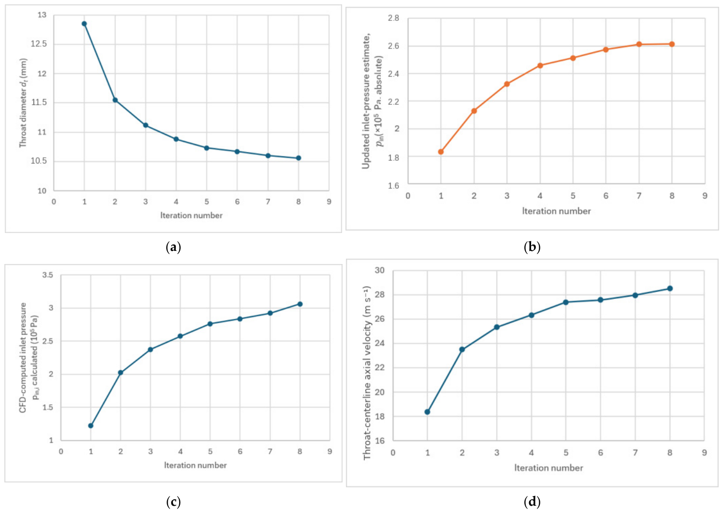
The automated cavitation-inception workflow converged after eight iterations. During the iterative sequence, the throat diameter progressively approached the value required to satisfy the prescribed cavitation-inception pressure under the adopted modeling assumptions. The final converged throat diameter was , corresponding to .
To report convergence in normalized form, the pressure residual defined in Equation (18) was expressed as a relative residual,
where
is the relative pressure residual at iteration
,
is the pressure residual defined in Equation (18), and
is the cavitation-inception pressure target used in the CFD-based iterative workflow.
The residual evolution is shown in
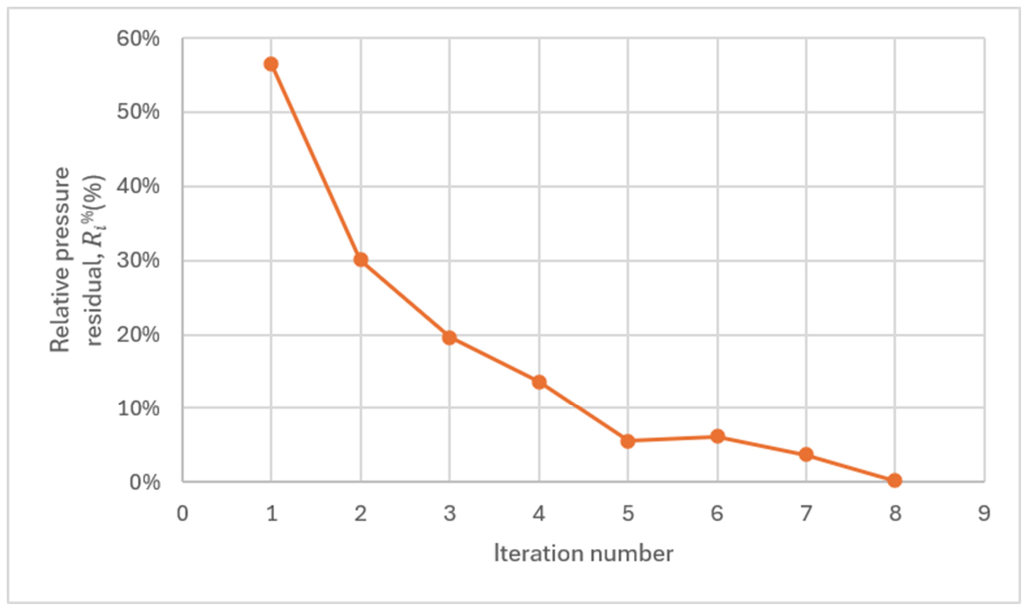
Figure 9. The relative residual decreased from
at the first iteration to
at the eighth iteration. A small intermediate increase occurred between iterations 5 and 6. This local non-monotonicity reflects the coupled update of the inlet-pressure estimate, the regenerated throat geometry, and the CFD-predicted throat pressure. It does not affect the overall convergence of the workflow toward the prescribed cavitation-inception condition.
The corresponding evolutions of the throat diameter, the analytical inlet-pressure estimate used by the Bernoulli predictor, the inlet pressure computed from the CFD solution, and the CFD-computed centerline axial velocity at the throat are shown in
Figure 10. During the iterative procedure, the analytical inlet-pressure estimate was updated from the throat-pressure residual and used only to generate the next candidate throat diameter.
It approached 261,385 Pa absolute, whereas the CFD-computed inlet pressure at the final iteration was approximately 306,211 Pa gauge. These two quantities have distinct roles and pressure references and are therefore not expected to coincide. The throat diameter converged toward mm, with a final pressure mismatch of approximately 0.168 kPa and a relative residual of 0.17%.
Table 5 reports the results of the eight iterations.
Table 5.
Results of the eight iterations.
Table 5.
Results of the eight iterations.
| Iteration | Throat Diameter (mm) | Absolute Residual (kPa) | Relative Residual (%) |
|---|
| 1 | 12.85 | 55.886 | 56.45 |
| 2 | 11.55 | 29.730 | 30.03 |
| 3 | 11.12 | 19.444 | 19.64 |
| 4 | 10.88 | 13.494 | 13.63 |
| 5 | 10.73 | 5.465 | 5.52 |
| 6 | 10.67 | 6.108 | 6.17 |
| 7 | 10.60 | 3.703 | 3.74 |
| 8 | 10.56 | 0.168 | 0.17 |
Figure 10.
Evolution of the principal sizing variables during the automated cavitation-inception workflow: (a) throat diameter; (b) analytical inlet-pressure estimate used by the Bernoulli predictor; (c) inlet pressure computed from the CFD solution; (d) CFD-computed centerline axial velocity at the throat. The throat diameter converges toward mm. The quantities shown in panels (b,c) have different computational roles and pressure references and are therefore not expected to coincide.
Figure 10.
Evolution of the principal sizing variables during the automated cavitation-inception workflow: (a) throat diameter; (b) analytical inlet-pressure estimate used by the Bernoulli predictor; (c) inlet pressure computed from the CFD solution; (d) CFD-computed centerline axial velocity at the throat. The throat diameter converges toward mm. The quantities shown in panels (b,c) have different computational roles and pressure references and are therefore not expected to coincide.
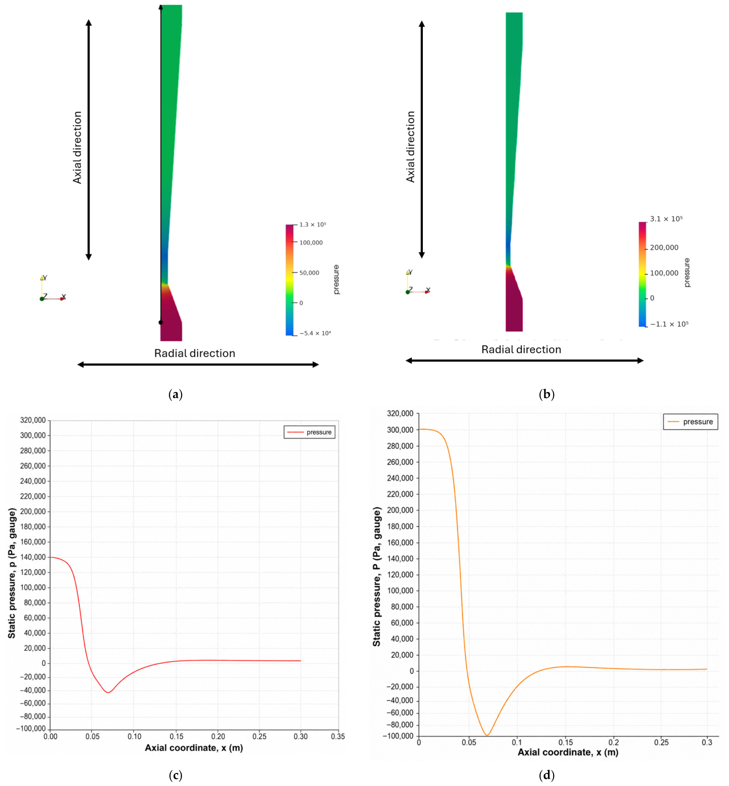
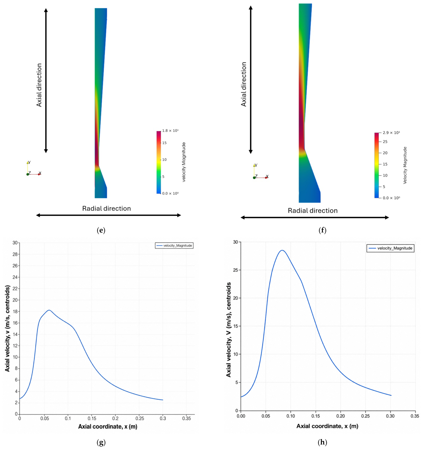
To examine the hydraulic response to throat reconfiguration,
Figure 11 compares the initial configuration, with
mm, and the converged configuration, with
mm. As the throat diameter decreased, the centerline axial velocity at the throat increased from 18.37 to 28.51 m s
−1, while the throat static pressure decreased from approximately −43.1 to −98.8 kPa gauge. In both configurations, the pressure decreases through the converging section, reaches its minimum in the throat region, and recovers downstream in the diffuser, whereas the velocity field shows the corresponding acceleration toward the throat and deceleration after it. The comparison therefore shows the coupled pressure and velocity response produced by the iterative throat-diameter adjustment.
The principal hydraulic quantities obtained at the converged geometry are summarized in
Table 6.
The numerical demonstration shows that the throat diameter associated with cavitation inception can be identified through an automated parametric workflow combining analytical initialization, geometry generation, mesh generation, finite-element CFD simulation, post-processing, and residual-based updating. Within the DCVA framework, this result is relevant because the throat diameter is not only a fixed design output, but also a candidate configuration variable for reconfigurable operation.
6. Discussion
A conventional Venturi operates with a fixed geometry and, under given plant conditions, imposes a cavitating operating point mainly determined by the throat section. The DCVA introduces a geometric operating variable, since the equivalent throat diameter can be adjusted during operation. For a given flow rate and pressure condition, varying changes the characteristic throat velocity and allows the cavitation regime to be shifted within a target operating window without modifying the external plant interfaces.
This aspect is relevant for complex liquids, where fluid properties and operating conditions may vary over time. In such cases, a fixed geometry sized for a single operating point may become suboptimal or insufficiently robust. Internal reconfiguration therefore decouples plant integration, which remains unchanged, from cavitation-regime control, which becomes adaptable.
Compared with previous variable-area or adjustable Venturi devices, the DCVA is not proposed only as a mechanical solution for changing the throat opening. Existing devices already show that modifying the effective flow area can regulate flow rate, pressure drop, or cavitation onset [
12,
13,
14,
15]. The distinctive contribution of the DCVA framework is the organization of internal geometric reconfiguration into a control-oriented structure. In this structure, the internal Venturi geometry is described through equivalent geometric parameters, bounded by an admissible design space, connected to plant-measurable indicators, and supported by commissioning and numerical configuration maps.
The introduction of the design space makes it possible to distinguish between conceptually admissible geometries and the subset effectively reachable within a given architecture. In DCVA-S, exploration is essentially one-dimensional, because the directly actuated degree of freedom is , whereas the equivalent throat-region length and effective transition angles are fixed by design or induced by the kinematics. In DCVA-M, reconfiguration is driven by station control inputs belonging to , generating a family of coupled internal profiles in which , , , and vary together.
DCVA-S and DCVA-M should therefore be viewed as two implementations of the same general concept rather than as competing solutions. DCVA-S prioritizes simplicity, repeatability, and direct calibration-map-based operation. DCVA-M expands the accessible configuration range by allowing not only throat modulation but also changes in transition shape and throat extent. This additional flexibility may be useful when more articulated cavitation-regime adjustment is required, but it also requires stricter definition of admissible configurations, more extensive calibration, and more careful operational management.
The numerical demonstration provides quantitative support for the proposed framework by connecting the parameterized circular Venturi geometry to a cavitation-inception design target. The convergence of the throat diameter toward , with a final relative residual of approximately , supports CFD-assisted configuration selection within the DCVA design logic.
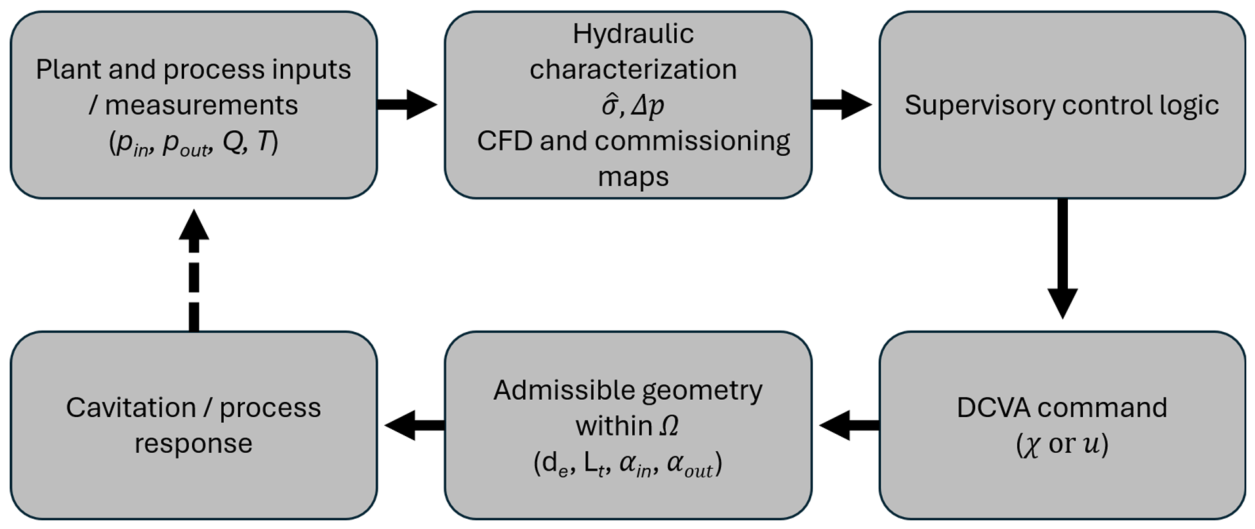
The geometric, hydraulic, and control elements of the DCVA framework are integrated in
Figure 12. Plant and process inputs define the operating requirements and constraints; architecture-specific control variables determine an admissible internal geometry within the design space
; hydraulic characterization and commissioning data then support configuration selection and subsequent updating from plant measurements.
In a closed-loop implementation, plant measurements would be used to update the operational indicator and compare it with a target cavitation window or process-performance criterion. The supervisory controller could then adjust the single control variable in DCVA-S or select and update an admissible profile in DCVA-M, while enforcing pressure-drop, actuator-stroke, liner-deformation, and smoothness constraints. The commissioning maps introduced in the present framework can therefore serve as a basis for future adaptive feedback control, rather than only as open-loop lookup tables.
Within this framework, is used as an operational proxy connecting plant-measurable quantities to the equivalent device geometry through . The proxy supports calibration-map construction, comparison among configurations, and selection of operating settings under a consistent estimation criterion. At the same time, does not replace direct measurement of the local cavitation number at the throat and should be interpreted in light of the assumptions behind the velocity estimate and distributed pressure losses.
The hydrodynamic description is therefore intentionally limited to a control-oriented operating indicator and does not constitute a full cavitation-flow model. Reynolds-number effects, turbulence, vapor volume fraction, dissolved gas content, choking, pressure recovery, cavitation shedding, erosion, and three-dimensional flow structures are expected to influence the actual cavitation regime. These effects require dedicated numerical analysis, experimental diagnostics, or application-specific benchmarking as the present CFD model is intended as a computational component of the DCVA design workflow rather than as a high-fidelity cavitation model.
In subsequent implementations, may be replaced or complemented by CFD-based or experimentally derived response maps linking admissible DCVA configurations to cavitation indicators, pressure fluctuations, and process outcomes. The same numerical model could also provide a virtual sensing layer, estimating throat-region hydraulic conditions from measurable quantities such as inlet pressure and process flow rate, since direct pressure measurement in the throat may be intrusive or difficult under high-velocity cavitating conditions. If calibrated and validated experimentally, this workflow could provide the computational basis for future physics-based digital-twin development.
Engineering reproducibility is addressed by defining the DCVA through explicit geometric and kinematic parameters, rather than through a single fixed geometry. Application-specific dimensions and material choices are not prescribed, since they depend on the intended duty, device scale, pressure range, material compatibility, and implementation constraints.
Repeatability is instead addressed through commissioning, by measuring the relevant geometry mappings and defining the corresponding operating maps.
The adoption of a reconfigurable Venturi also introduces mechanical and material constraints. The repeatability of the equivalent geometry may be affected by hysteresis and mechanical tolerances, while liner durability depends on stress distribution and cyclic deformation. Material selection should therefore account for tensile behavior and elastomer performance under repeated deformation [
26,
27]. Chemical compatibility, allowable strain, fatigue resistance, and reinforced-elastomer behavior also remain implementation-specific constraints [
28,
29].
Hydraulic benchmarking is likewise required. Each implementation should be compared with fixed-geometry and variable-area Venturi devices in terms of pressure drop, cavitation onset, operating stability, and flow-control behavior [
32,
33,
34]. Broader cavitation-device studies further indicate that device architecture, scale, and intended process duty strongly affect practical applicability and technology transfer [
35,
36].
Consistent with this scope, the figures are intended as functional schematics of the proposed architectures rather than as manufacturing drawings or experimental layouts. Quantitative engineering information such as absolute dimensions, tolerances, actuation strokes, material specifications, pressure-tap locations, and measurement plans must be defined for a selected prototype scale and process duty.
The proposed framework is particularly relevant for industrial processing applications in which properties of the treated medium may vary during treatment and stable control of the cavitation regime is desirable. In such cases, the DCVA can operate as a reconfigurable development platform for exploring candidate configurations and identifying suitable operating windows. It may also support adaptive in-line operation when process conditions or treatment targets change over time. This perspective is consistent with recent studies emphasizing cavitation-intensity assessment, three-dimensional flow effects, and data-driven optimization in Venturi cavitation systems [
37,
38,
39].
From a recycling- and resource-valorization-oriented perspective, the main potential interest of the DCVA framework lies in supporting future hydrodynamic cavitation devices that are more adaptable to real waste and by-product streams. In food-processing liquids, matrix properties and treatment objectives may vary substantially during operation [
40,
41]. In waste-derived streams or biomass suspensions, composition, solid fraction, and extractable compounds may vary between batches or during treatment. Adaptive geometric reconfiguration could therefore be explored as a future strategy to maintain the cavitation regime within a useful operating window, reduce over-conservative operation, and support more resource-efficient valorization routes [
42,
43].
On this basis, the next stages of development may include calibration of the control-to-geometry relationship, construction of configuration– maps under representative operating conditions, verification of the accessible operating window in terms of pressure drop, and correlation of configuration changes with independent cavitation indicators and process outcomes.
7. Conclusions
The Dynamic Circular Venturi Adaptive (DCVA) was formulated as a framework for circular Venturi devices with reconfigurable internal geometry. The approach preserves the external body and plant interfaces while treating the internal Venturi profile as an adjustable operating variable. This enables cavitation-regime modulation beyond the limitations of a fixed geometry selected for a single nominal operating condition.
The framework defines equivalent geometric parameters, an admissible design-space logic, and an operational cavitation proxy based on plant-measurable quantities. Two representative implementations were considered: DCVA-S, based mainly on single-parameter throat modulation, and DCVA-M, based on multiparametric profile reconfiguration. Together, they describe different balances between mechanical simplicity, accessible configuration range, and calibration requirements.
The automated CFD-assisted workflow converged after eight iterations to a throat diameter of mm, with a final pressure mismatch of kPa and a relative residual of . These results demonstrate that the parametric procedure can identify a candidate throat configuration associated with the prescribed cavitation-inception condition and support commissioning-map development.
The principal advantage of the DCVA framework is that the internal geometry can be adjusted while the external body and plant connections remain unchanged, enabling cavitation-regime adaptation without replacing the in-line device.
At the framework level, the throat adjustment range is defined by , corresponding to . A device-level numerical adjustment range and response time cannot be specified because they depend on actuator selection, available stroke, liner properties, pressure loading, and prototype scale; their determination requires mechanical realization and experimental characterization under representative operating conditions.