Article

3D FFF-Type Printer Upgrade for the Use of Viscous-Filled Polymeric Materials

Department of Technical Studies, College of Polytechnics Jihlava, Tolsteho 16, 586 01 Jihlava, Czech Republic
*
Author to whom correspondence should be addressed.
J. Manuf. Mater. Process. 2026, 10(7), 222; https://doi.org/10.3390/jmmp10070222
Submission received: 29 April 2026 / Revised: 19 June 2026 / Accepted: 25 June 2026 / Published: 27 June 2026

Abstract

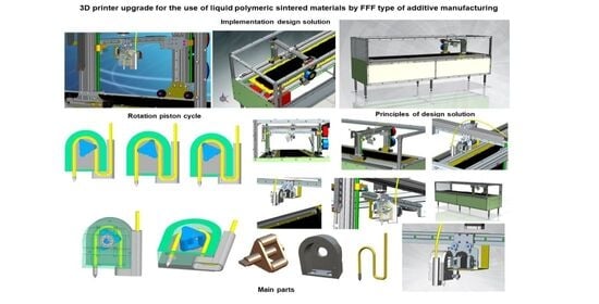
Recently, there has been a significant expansion of additive technologies, especially Fused Filament Fabrication (FFF). This article aims to upgrade a commercial 3D printer to develop viscous polymeric materials, as this option is not currently available. The FFF method is primarily used with thermoplastics and elastomers in filament form. However, materials derived from various water-soluble acrylates offer significant potential, with advantages including environmental friendliness and desirable mechanical and visual properties. The possibility of using a viscous polymer as a carrier for metal material prior to sintering is also a significant factor. The aim of the text is to present the preparation of a 3D printer suitable for printing the above materials. The main requirement was to modify the selected printer with minimal interference with HW and SW. We mainly focused on adjusting the print head. A new prototype for the printing of viscous polymeric materials was visualized. Furthermore, the individual components were designed and printed; a functional system capable of processing these materials was assembled.

Graphical Abstract

1. Introduction

Additive manufacturing technology is one of the most widely used methods for processing polymeric materials [1]. One of the most popular 3D printing methods is Fused Deposition Modeling (FDM) [2,3]. It is an additive manufacturing technology that was patented by S. Scott Crump [4]. FDM is a registered trademark of Stratasys [5] and cannot be used by other FDM printer manufacturers. Therefore, the abbreviation FFF (Fused Filament Fabrication) is used to refer to the same type of additive technology. Additive production is the process by which a product is formed by the gradual deposition of thin layers on top of one another. The principle of FFF technology is to melt a polymeric material or metal filament in an extrusion head, which then extrudes the melt onto a substrate and gradually moves a very thin layer of material in the horizontal cross-sectional plane of the future product [6]. FFF technology is an advanced method for prototyping in the automotive, medical, and construction industries [7,8,9,10,11,12,13]. Nowadays, a wealth of materials can be processed using this technology. As already indicated, many polymeric materials are based on thermoplastics or elastomers.
The most common materials for FFF technology include thermoplastic materials such as polylactic acid (PLA) [14,15,16,17,18,19], acrylonitrile-butadiene-styrene (ABS) [20,21,22,23], polyethylene terephthalate glycol (PET-G) [24,25], polyethylene terephthalate (PET) [24,26,27], and polycarbonate (PC) [28,29,30]. Commonly, various additives are attached to these materials to improve their properties. However, these additives are mixed with polymeric materials without a covalent bond. Flame retardants [31,32], lubricants [33], stabilizers [34], and fillers [35,36,37] are commonly used as additives in polymeric materials. Because there is no covalent bond, additives are lost from the material over time. The advantage of viscous polymer materials based on different types of acrylates is that they can be synthesized with preselected properties through monomer composition. Their properties depend on the copolymers of acrylic and methacrylic acid used to affect the hardness and physical-mechanical properties. The advantage of these materials is resistance to UV radiation, chemicals, abrasion, and wind. Furthermore, the resulting film exhibits excellent adhesion and transparency.
Within additive technologies, there is a method for processing viscous polymeric materials. It is stereolithography (SLA), which cures thermoplastic-based materials using ultraviolet (UV)/light-emitting diode (LED) radiation. Materials based on epoxy and polyester resins, based on solvent systems, are processed [38,39,40,41]. The problem with these materials is not the principle of SLA technology, but rather the high viscosity or high light scattering from latex particles, which can reduce printing accuracy or require parameter adjustments. This disadvantage could be addressed by a modified FFF 3D printer that processes these materials after modification.
The preparation of modified 3D printers has been reported in the medical field [42,43,44]. The modification of the FFF printer was solved for photopolymeric resin, with geometric accuracy in the X, Y, and Z directions of ±0.1 mm using a 5 mL syringe, a 22-gauge needle, and commercial SLA resin [45].
A significant research challenge in the field of additive manufacturing is therefore the processing of highly viscous polymer solutions and suspensions (e.g., water-soluble acrylate-based materials, which offer a wide range of benefits, from environmental sustainability). Another key application is the use of viscous polymer carriers (binders) filled with metal particles, which enable the production of “green body” semi-finished products for subsequent sintering, thus opening the way to low-cost 3D printing of metals. Currently, commercially available FFF printers cannot process these materials in their standard configuration, limiting their use in advanced materials engineering. This work, therefore, focuses on upgrading the design of a commercial 3D printing system to enable precise extrusion of highly viscous polymer media. The main technical requirement was to modify the existing platform with minimal intervention in the hardware and software architecture (HW/SW), thereby maintaining the system’s stability. The research focuses on the development and implementation of an innovative print head that replaces the standard filament feeder with a mechanism optimized for the rheology of viscous liquids. As part of the work, a prototype was designed and visualized, and its components were subsequently manufactured using additive methods and integrated into a functional unit. The resulting system enables processing materials without the need for immediate curing via UV radiation or LEDs, thereby expanding the method’s applicability to a wide range of chemically solidified or thermally stabilized polymer mixtures. The final material for 3D printing with this upgraded 3D printer will be a viscous polymeric material, either a solidifying polymer or one containing metal particles, for subsequent sintering. The advantage is the ease of preparing a paste of suitable consistency for subsequent direct printing using the FFF method.

2. Materials and Methods

2.1. Materials

PET-G filament (Ø 1.75 mm; accuracy: 1.75 ± 0.05 mm), from Fillamentum Manufacturing Czech s.r.o. (Hulin, Czech Republic), was chosen for the printed parts of the upgraded 3D printer. It is a black filament with the following properties: density 1.27 g·cm−3, tensile strength 26 MPa at break (by ASTM D638), flexural strength 71 MPa (by ASTM D790), and Rockwell hardness 105 (by ASTM D785).
A Prusa I3 3D printer (Prusa Research, Prague, Czech Republic) with a nozzle size of 0.4 mm was used. A work area of 8000 cm3 (200 × 200 × 200 mm) with an integrated LCD was applied for redesigning.
Components to improve the existing 3D printer included a motion carrier (CSN 11 500; DIN St 50-2), a silicone-based material tube, a peristaltic pump rotor with basic dimensions of 94 × 10 mm (CSN 11 500; DIN St 50-2), a pad (CSN 11 500; DIN St 50-2), a brass nozzle, bearings with dimensions d = 12 mm, D = 28 mm, b = 8 mm and rs = 0.3 mm (CSN 02 4630; DIN 625), and a screw (CSN 02 1232; DIN 7971). These are commonly available components purchased in specialist shops.

2.2. Methods

3D printing was performed on a DeltiX (TriLAB, Hradec Kralove, Czech Republic) (nozzle size 0.4 mm) using FFF technology. A 250 × 300 mm working area with an integrated LCD was implemented. The X/Y resolution was 0.4 mm using a nozzle, and the Z resolution was 0.4 mm.
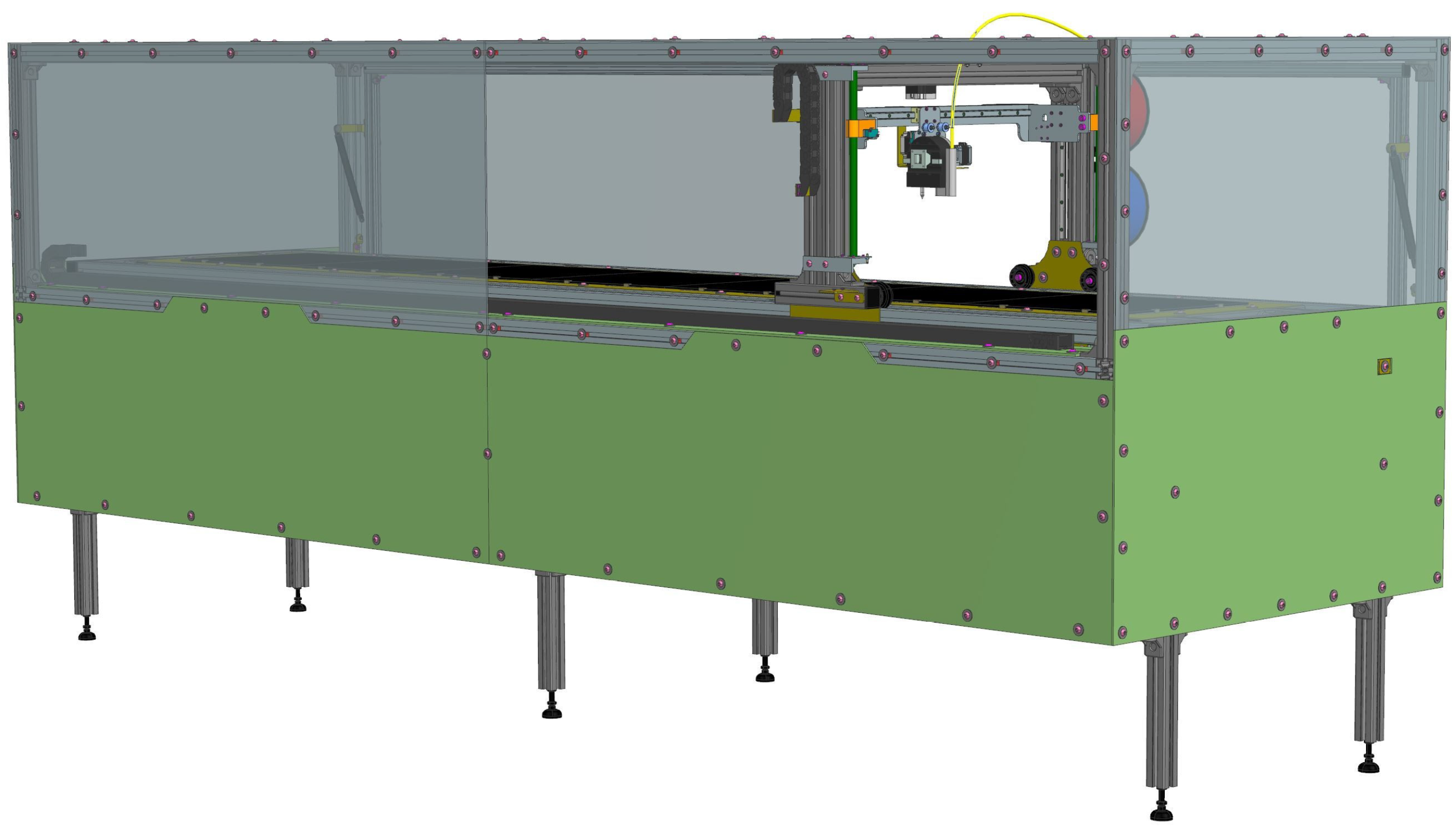
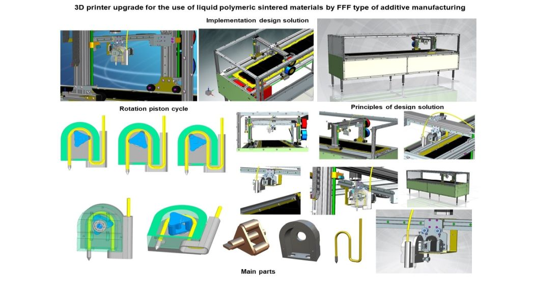
Models were designed and edited using both parametric and nonparametric methods. The process of freeform surface modeling enabled the creation of more complex models. Computer-Aided Design (CAD) diagnostic tools were used for primary analyses. Computer-Aided Engineering–Finite Element Analysis (CAE–FEM) was used for advanced study. Models were created and edited using SW NX Siemens ver. 2312 (Siemens, Plano, TX, USA) and exported in stereolithography format (.stl). Postprocessing involved creating ISO G-codes. The printer management program was developed in SW Slic3r Prusa Edition Version 1.31.6-prusa3d-win64 (Prusa Research, Czech Republic) from the *.stl format of the model. The nozzle-extruder path was generated at defined levels with specified material, temperatures, and print speeds. The postprocessor includes information on the material consumed and the print time. ISO G-code can be created and edited manually. It is a syntax text file. The 3D model of the assembly was implemented on a generic 3D printer, as shown in Figure 1.

2.3. Application Case Study

The design is primarily intended for printing materials with a moderate viscosity. Instead of rigid filaments, materials with a certain degree of fluidity are used. The principles presented allow for the use of a wide range of viscous materials. This content presents a design solution based on components and assemblies, with an emphasis on shape and dimensions. The material used is not the primary subject of research but serves to verify the proposed solution. The acrylic component provides viscosity, while the metal component provides mechanical and other physical characteristics. An advantage of this solution is the ability to prepare custom materials without an extruder to produce filament, which is particularly significant for materials containing multiple components. The advantage of the peristaltic pump lies in its independence from a material reservoir. Separating the extrusion pressure at the pump level ensures independence from the material feed. The hopper can be opened. Printing can continue indefinitely, or dosing can be performed for a precisely specified duration. Solutions with a pressure hopper based on an electromechanical, hydraulic, or pneumatic piston are limited by the chamber’s capacity. A certain disadvantage, namely a harmonic pressure curve, is eliminated by a combination of parameters: the eccentricity of the rotating piston, the rotation speed, and the cross-sectional flow area. All of this is taken into account in the verification experiment results and the discussion. The effect of the rotary piston’s eccentricity on maintaining constant rotational speed and extrusion nozzle cross-section is being investigated. Research into combining and optimizing printing parameters is specific to different materials and relates to subsequent materials research.
An advantage of printing thin layers of material containing metal particles is the ability to create extensive conductive connections or to produce relatively precise components to ensure electromagnetic compatibility. With more viscous materials that allow for multi-layer printing, it is possible to produce large-area prints on large-format printers, regardless of the limitations of the supplied material. The use of a 3D printer is particularly significant for the ease with which complex, large-area shapes can be produced, such as conductive tracks or flush-mounted EMC shielding elements. The equipment can also be used to print from viscous polymeric materials without the need for sintering. In the context of available manufacturing technologies, this process can be considered the inverse of chemical and electrochemical manufacturing processes.

2.4. Methodology of Design Research

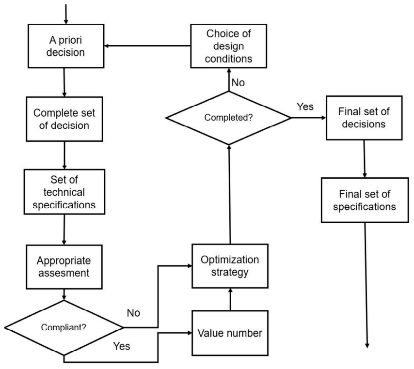
The development of the device follows the usual research and development process. Due to the research nature of the topic and its specificity, the primary input factors are derived from the search for publication outputs, as stated in the relevant parts of the presented text. Primary data are created in CAD applications using parametric methods. The model’s key parameters enable systematic changes, parameter interconnection through expressions, and associated change management across development and research. The research analysis of the virtual prototype is carried out in the context of the assembly. For the development of individual components and the whole assembly, a combination of the bottom-up (component development separately) and top-down (component development in the assembly context) methods is used. Kinematic and structural analysis is performed using a CAE tool. Dimensional analyses are performed using a diagnostic tool within CAE, with PMI (Product Manufacturing Information) at the level of a virtual prototype. The primary input source for the decision-making mechanism is a conceptual study. The decision mechanism is shown in Figure 2.
The design principle is to determine the optimal dimensions and positions of the assembly’s critical elements to ensure reliable, continuous feeding of viscous material. The above scheme is applied to optimize the functional parameters. The decision phases encompass the evaluation of the kinematic analysis, the assessment, and the optimization of the model. It is an iterative, converging process that results in optimized component models and entire assemblies. Technical documentation in the form of 3D data is implemented in the optimized models, which serve as the basis for producing a real prototype. If deviations are found during testing a real prototype, the optimization and redesign process can be repeated using the defined input parameters.

3. Results

3.1. Upgrade and Preparation of Parts for the 3D Printer

The essential step in modeling involved the rotating part of the peristaltic pump. Based on the dimensions of the guide shafts and the silicone hose, we created the main body and cover, which include bearings to support the pump’s rotating shafts. Initially, we had more parts that fit together and were movable, but this construction was too complex to manufacture, so we significantly simplified the entire model. The individual sub-elements were then glued to the central part of the pump body (stepper motor holder, motion carrier, and hose holder). Subsequently, the entire body must be attached to the shafts using cable ties. We reworked and simplified the actual construction several times before finalizing it.
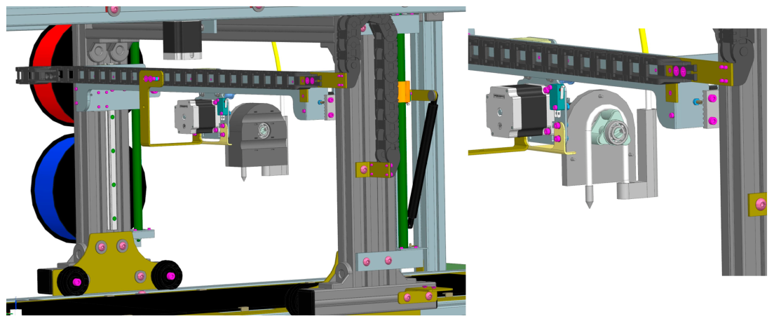
All parts (Figure 3) for the improvement of the existing 3D printer Prusa I3 (Prusa Research, Prague, Czech Republic) with a nozzle size of 0.4 mm were printed from PET-G material. It is a stable material with good mechanical properties, good machinability, and resistance to thermal stress [46,47]. We used a nozzle diameter of 0.4 mm, a bed temperature of 90 °C, a print temperature of 235 °C, a 100% fill density, and a layer height of 0.2 mm. Print speed was set to 30 mm.s-1, the number of perimeters was 2, and the infill style was set to 100% straight, with a flow rate of 100%.
In Figure 1, we can see a 3D preview of the detailed solution of the main part of the system.

3.2. Design Solution

The comprehensive set of design solutions contains individual components, or entire modules, from the following categories:
-
Designed parts produced by conventional production technologies.
-
Designed parts produced by additive or hybrid technologies.
-
Non-standard catalog parts.
-
Standardized catalog parts.
Parts manufactured using conventional technologies are designed according to standard procedures and specifications to ensure the required shape and dimensions, including appropriate tolerances, with a primary focus on the part’s functionality in assembly, manufacturing, and measurement. Parts produced by additive technologies are designed in accordance with the production characteristics of the FFF printing equipment used. This technology is for parts that can be dimensioned based on the characteristics of polymeric 3D printing materials using structural simulations. To ensure reliable function, assembly characteristics, and surface quality, especially in the inner part of the device, post-processing of 3D-printed parts is performed using modification by conventional Computer Numerical Control (CNC) milling and turning. CNC milling is not particularly well-suited to achieving precise contours on curved shapes. 3D models are ready for production at the center of the tolerance field. This ensures the independence of the production technology when using the exact model for further production documentation. Only specific dimensions in the 3D model can be described with specific tolerances, e.g., dimensions from a set of tolerances for precise mounting and fitting.
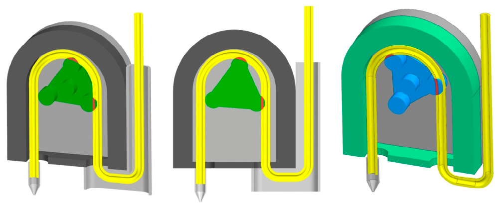
The basis of the modification of a 3D printer using the FFF principle is the dismantling of the printhead, fusing, and dosing filament. A peristaltic pump is connected instead, into which viscous material has been sucked. In principle (see Figure 4), the flexible pump tube is alternately compressed and released. During the rotor’s slow rotation, the hose gradually deforms, forming a small viscous volume in the tube, which is then pushed out of the hose by one of the three vanes, creating a vacuum behind the vane. The direction of rotation determines whether the viscous fluid is dispensed onto the printing surface.
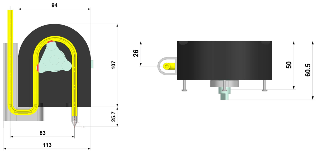
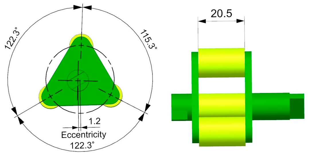
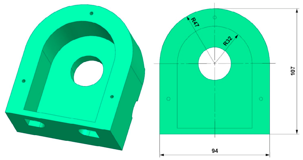
The three vanes are connected to a stepper motor, determining the amount of fluid delivered to the printing surface. The stepper motor has been chosen for simplicity of implementation into the existing printer, which we will modify. The G-code used to control the printer contains information about the amount of material printed on the printing surface. This value is affected by the string length and the nozzle diameter. By changing these parameters, we can influence the direction and number of revolutions of the peristaltic pump rotor (see Figure 5). Figure 5 shows the rotating part of the pump, which alternately compresses and releases the silicone tube, which is placed in the main body shown in Figure 6. The fundamental problem we solved was the actual implementation and connection of the peristaltic pump to the 3D printer. We dismantled the original printhead and instead connected the peristaltic pump’s main body to the existing two axes.
The main body (see Figure 6) was designed to attach to the X-axis linear bearings and to accommodate a ball bearing that would house the peristaltic pump’s rotor shaft.
Subsequently, it was necessary to connect the main body to the X-axis using plastic cable ties and connect the stepper motor holder to the rear wall, including the attached stepper motor, precisely to the rotor axis. The next step in the modification was to attach the X-axis motion carrier from the X-axis stepper motor. These carriers need to be attached to both sides of the main body along the timing belt axis. Here, the tensioned X-axis timing belt is connected, and X-axis motion is resolved. We did not address the additional tension of the timing belt; this will be one of the possible further improvements to our 3D printer upgrade. It is also necessary to connect the hose holder to the main body, insert the hose, connect the nozzle to the main body, and connect the main liquid reservoir.
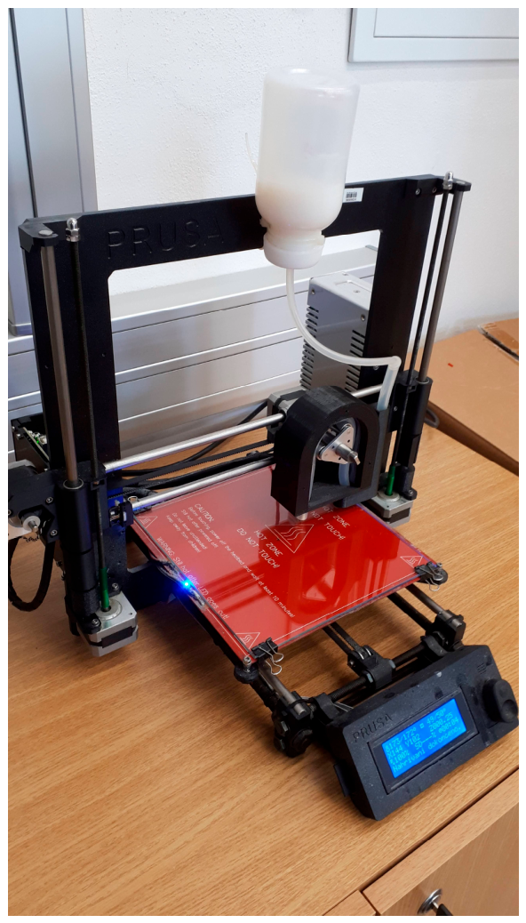
A cover was used to anchor the peristaltic pump’s rotor, which we attached to the peristaltic pump’s main block. There is also a ball bearing to support the pump rotor’s axis. An integral part of the treatment is the nozzle, attached to the hose’s end. A preview of the comprehensive model and the implementation of the modification is shown in the following figure. The main container must be located above the printer. The liquid itself must be sucked in by rotating the peristaltic pump before 3D printing.

3.3. Generic 3D Printer Application

The basic program generated from the input 3D object G-code for a 3D printer is Slic3r Prusa Edition. It is possible to control a parameter that affects the peristaltic pump’s rotation by varying the filament diameter. This parameter affects how much material will be transferred to the motherboard. Comparisons of values for different filament diameters show how the amount of material fed changes. By comparing the G-code values of the same object for different diameters, we can demonstrate the change.

3.4. G-Code Modification

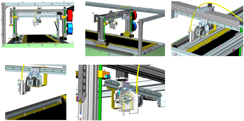
The presented solution can be implemented in most commercially available FFF 3D printers. It can replace the existing print head for 3D printing with filaments. Easy interchangeability and independence from the infrastructure allow both methods to be combined. An example of a non-commercial large-format printer is shown in Figure 7. A detailed view of the rotary piston pump assembly is shown in Figure 8.

3.5. Dependence of Printed Fiber Quality on Flow Rate

The primary technical parameter being tested is the degree of eccentricity in the rotating piston’s planetary motion [48,49,50]. This eccentricity, in conjunction with the angular spacing of the radial piston cylinders and their geometric parameters, influences both the flow rate of the viscous material and the smoothness of the flow [51,52,53,54,55]. The pitch-circle diameter of the radial cylinders influences the flow rate. The angular pitch between the main piston cylinder and the auxiliary piston cylinders influences the smoothness of flow. The cylinder eccentricity simultaneously influences the flow rate and smoothness. The eccentricity value is the subject of testing. The results obtained are incorporated into the technical design of the assembly segment shown in Figure 5. The value of 1.2 mm is an approximation based on a combination of 9 measurements across three types of viscous materials and three different spacings. The reference test parameters are listed in Table 1.
Diameter of the viscous material feed tube: 4 mm inner diameter, 6 mm outer diameter. This tube is made of PTFE, as specified in the catalog. The test speed corresponds to the print head’s movement speed during printing and remains constant throughout the print. It corresponds to the optimal flow rate for the required amount of material, ensuring a continuous stream of printed filament.
Tested eccentricities: 0.5, 1, 1.5 mm. At lower eccentricities, reliable material feeding is no longer achieved. At higher eccentricities, the printed layer was non-homogeneous and, in some cases, even interrupted. The test material consists of an acrylate-based polymer mixed with 316 L stainless steel powder. Viscosity is tested using the rotational viscometer PCE-RVI 2 (PCE Instruments, Meschede, Germany). The viscosity as a function of metal powder content is shown in Table 2. The rotational viscometer was utilized to determine viscosity. The spindle was designated as L0 and operated at 60 RPM for low-viscosity applications.
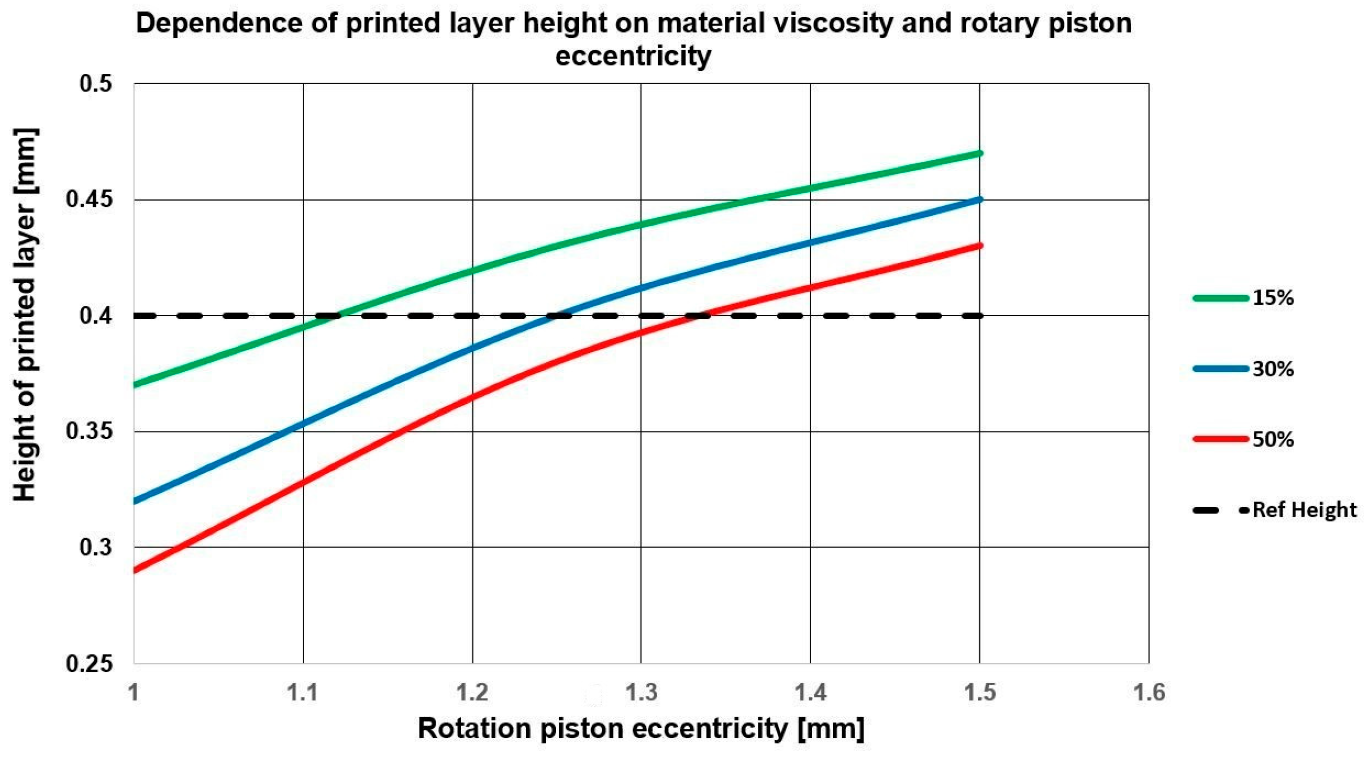
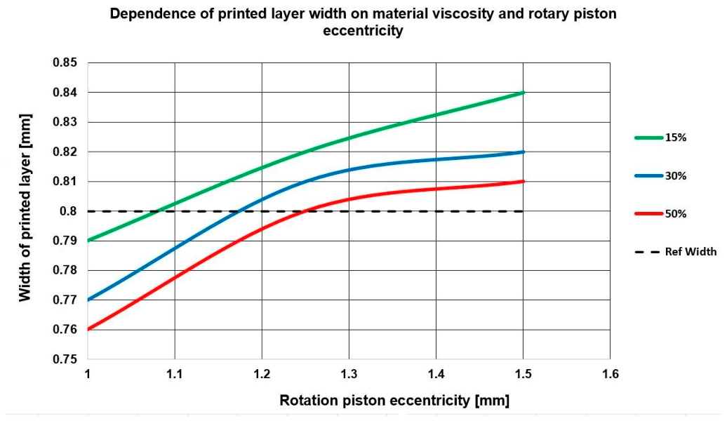
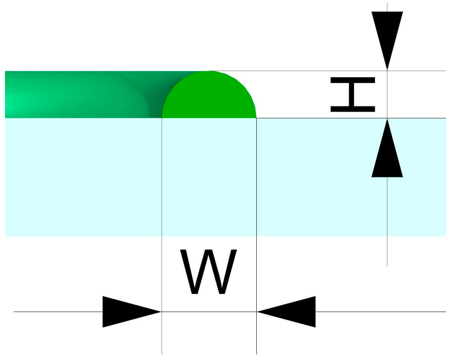
The parameters being tested are the width of the printed filament, the height of the filament relative to the base, and the ratio of these two parameters. The cross-sectional shape of the printed filament, with the height and width parameters marked, is shown in Figure 9. The expected width of the printed filament is based on a nozzle diameter of 0.8 mm. The nozzle setting determines the expected height. A high flow rate causes the printed filament to spread. The result is poor print quality and possible inhomogeneity of the print structure. A low flow rate causes an uneven, even interrupted, filament structure, leading to an inhomogeneous porous structure. The test results are shown in the graphs in Figure 9 and Figure 10 and are also quantitatively evaluated in Table 3.
An analysis of the results shows that the dimensions of the printed filament with an eccentricity of 1.25 mm most closely match the expected parameters for all viscosity types in terms of height and width, with a reference layer thickness of 0.4 mm and a reference layer width of 0.8 mm.
The parameters Width—W and Height—H are shown in Figure 11.
The final assembly used for testing is shown in Figure 12. The rotary piston with accessories was implemented on a device originally designed for rigid filaments.

4. Discussion

The main technical parameter is the rotary piston’s eccentricity. Experimental measurements have determined a value of 1.2 mm. Combined with the intermittent piston action on the viscous material in the feed tube, this ensures a continuous flow with acceptable quality characteristics. This is a multifactorial problem, with variables including the diameters of the print nozzle orifice and the print hose, and the material type. Covering all technical and technological parameters is an extensive, long-term research challenge. A key starting point for determining the material’s mechanical parameters is ensuring structural consistency. This is achieved by defining the flow and extrusion parameters during printing. Given the testing conducted on various material characteristics, including filler and metal powder content, the influence of viscosity on the result parameters is evident. For an eccentricity of 1.25 mm, the values in all three tested cases are closest to the reference values. In addition to dimensional characteristics, a significant factor is the consistent quality of the printed filament, which depends primarily on the flow rate, controlled by eccentricity. Low eccentricity and insufficient flow rate lead to significant layer thinning, increasing the risk of breakage. Conversely, a high flow rate combined with high eccentricity, where unevenness is pronounced, results in significant thickness variations in the printed layer. Both low and high flow rates affect the inhomogeneity of layered material structures. The dependence of eccentricity on viscosity is insignificant within the range of material parameters and corresponding viscosities, and further technical expansion of the device to include variable eccentricity is not warranted. The aforementioned technical characteristics could be significant when using other materials with different viscosities, where the proposed principle would be tested.
A distinctive feature of the design is the use of a peristaltic material-feed system incorporating a rotary piston [56,57,58]. The main advantage of the rotary piston is the separation of the pressure extrusion section from the filling section. Material can be replenished in the hopper without interrupting the printing process, which is particularly advantageous for large-format printing. A slight deviation from the exact continuity of the supplied quantity of viscous material does not pose a risk of compromising the quality of the printed product. The use of a rotary piston with adjustable eccentricity allows the equipment to be adapted for print optimization and quality control. For the research and development of this design solution, a custom rotary piston was used and further optimized through testing of selected materials. This is a multidimensional task involving a wide range of variable parameters. An advantage of the system is its openness to further adaptations, optimized based on the equipment’s overall size, flow control, and the product’s quality characteristics. The in-house-manufactured rotary piston is fully suited to the proposed concept. The use of commercial solutions requires adaptation, particularly in piston mounting and in defining rotational eccentricity relative to the arc of the hose line, consistent with the results presented in Table 3 and the subsequent graphical representation. The use of a commercial piston is being considered for potential production of multiple units, in which case the pump housing and mounting configuration are expected to be adapted in accordance with the research results. The option of using a piston-type hopper is relevant; however, it is a fully enclosed system that requires interrupting the printing process for larger formats. The higher pressure available with a piston-type solution may be suitable for high-viscosity materials, where a sufficient continuous supply of material to the extrusion die may not be reliably maintained. For high-viscosity materials, controlling material feed and flow rate via a pneumatic system may be considered. The complexity of flow control is similar for solutions with rotary and linear pistons. Controlling flow via a pneumatic system increases the complexity of what is, in principle, a low-cost solution. A significant factor is the ability to control the flow of material containing metal particles, which requires consideration of abrasive properties that can rapidly wear out the linear-piston mechanism. The rotary piston solution represents a versatile option for upgrading commercial printers to process a range of viscous materials. Precisely defining the optimal viscosity range and application possibilities is the subject of long-term testing during equipment operation. The starting points for optimization are design modifications to the existing, proven functional system and the simultaneous development of viscous materials.

5. Conclusions

The present study describes the modification of a commercially available 3D printer for subsequent use with highly viscous polymeric materials. The operation of a 3D printer involves gradually applying materials to create a product using FFF technology. Thanks to advances in technology, highly viscous polymeric materials can be used for their ecological properties. It was possible to redesign a commercially available 3D printer by preparing new components, resulting in a functional printer that doses liquids at an adjustable speed and processes thermoplastic- or elastomer-based filaments using conventional modeling techniques. The next stage of development is the preparation of new types of highly viscous polymeric materials with improved properties. Based on the modified 3D printer, we obtained the following dimensions, which can be safely used for 3D printing: 160 × 200 × 150 mm (X × Y×Z). We therefore prepared a new print head with a low-cost modification that is functional and enables the printing of polymeric materials in the liquid state. Another potential application could be printing from other viscous materials. The preparation of viscous material is technologically much less demanding. The paste-like consistency can be achieved with a wide range of mixing equipment. An important factor is the possibility of using a viscous material as a carrier for the main material. This characteristic is particularly important for 3D printing of metal materials using the FFF method, which is subsequently sintered by thermal or chemical treatment.

Author Contributions

Conceptualization, K.D. and M.B.; methodology, K.D.; software, M.B.; validation, L.Z. and K.D.; formal analysis, L.Z.; resources, J.D.; writing—original draft preparation, K.D. and L.Z.; writing—review and editing, K.D., J.D. and L.Z.; visualization, M.B.; supervision, K.D. and M.B.; project administration, K.D.; funding acquisition, K.D. All authors have read and agreed to the published version of the manuscript.

Funding

This research was supported by the College of Polytechnics Jihlava, under Grant No. INT/2025/0004, “Research into the technological and mechanical characteristics of 3D printing sintered materials”.

Data Availability Statement

The original contributions presented in this study are included in the article. Further inquiries can be directed to the corresponding author.

Conflicts of Interest

The authors declare no conflicts of interest. The funders had no role in the design of the study; in the collection, analyses, or interpretation of data; in the writing of the manuscript; or in the decision to publish the results.

Abbreviations

The following abbreviations are used in this manuscript:
3D3-Dimensional
ABSAcrylonitrile-butadiene-styrene
FFFFused Filament Fabrication
CADComputer-Aided Design
CAEComputer-Aided Engineering
FEMFinite Element Method
LCDLiquid Crystal Display
LEDLight-Emitting Diode
PCPolycarbonate
PETPoly Ethylene Terephthalate
PET-GPoly Ethylene Terephthalate Glycol
PLAPolylactic Acid
UVUltraviolet

References

  1. Wendel, B.; Rietzel, D.; Kühnlein, F.; Feulner, R.; Hülder, G.; Schmachtenberg, E. Additive processing of polymers. Macromol. Mater. Eng. 2008, 293, 799–809. [Google Scholar] [CrossRef]
  2. Seregi, B.L.; Ficzere, P. Refined Cost Calculation Framework for FDM Parts. J. Manuf. Mater. Process. 2025, 9, 321. [Google Scholar] [CrossRef]
  3. Thumsorn, S.; Prasong, W.; Ishigami, A.; Kurose, T.; Kobayashi, Y.; Ito, H. Influence of Ambient Temperature and Crystalline Structure on Fracture Toughness and Production of Thermoplastic by Enclosure FDM 3D Printer. J. Manuf. Mater. Process. 2023, 7, 44. [Google Scholar] [CrossRef]
  4. Crump, S.S. Apparatus and Method for Creating Three-Dimensional Objects. US5121329A, 9 June 1992. [Google Scholar]
  5. Ahn, S.; Lee, C.S.; Jeong, W. Development of translucent FDM parts by post-processing. Rapid Prototyp. J. 2004, 10, 218–224. [Google Scholar] [CrossRef]
  6. Novakova-Marcincinova, L.; Novak-Marcincin, J.; Barna, J.; Torok, J. Special materials used in FDM rapid prototyping technology application. In Proceedings of the 2012 IEEE 16th International Conference on Intelligent Engineering Systems (INES), Lisbon, Portugal, 13–15 June 2012; IEEE: New York, NY, USA, 2012; pp. 73–76. [Google Scholar]
  7. Corcione, C.E.; Palumbo, E.; Masciullo, A.; Montagna, F.; Torricelli, M.C. Fused Deposition Modeling (FDM): An innovative technique aimed at reusing Lecce stone waste for industrial design and building applications. Constr. Build. Mater. 2018, 158, 276–284. [Google Scholar] [CrossRef]
  8. Singh, D.; Singh, R.; Boparai, K.S. Development and surface improvement of FDM pattern based investment casting of biomedical implants: A state of art review. J. Manuf. Process. 2018, 31, 80–95. [Google Scholar] [CrossRef]
  9. Cailleaux, S.; Sanchez-Ballester, N.M.; Gueche, Y.A.; Bataille, B.; Soulairol, I. Fused Deposition Modeling (FDM), the new asset for the production of tailored medicines. J. Control. Release 2021, 330, 821–841. [Google Scholar] [CrossRef] [PubMed]
  10. Peng, X.; Zhang, M.; Guo, Z.; Sang, L.; Hou, W. Investigation of processing parameters on tensile performance for FDM-printed carbon fiber reinforced polyamide 6 composites. Compos. Commun. 2020, 22, 100478. [Google Scholar] [CrossRef]
  11. Tse, K. Polymer FDM for High-Performance Facades: Digital Tools for Designing Performative Aesthetics with Polymer FDM. Master’s Thesis, University of Calgary, Calgary, AB, Canada, 2020. [Google Scholar]
  12. Dave, H.K.; Patel, B.H.; Rajpurohit, S.R.; Prajapati, A.R.; Nedelcu, D. Effect of multi-infill patterns on tensile behavior of FDM printed parts. J. Braz. Soc. Mech. Sci. Eng. 2021, 43, 23. [Google Scholar] [CrossRef]
  13. Peng, T.; Sun, W. Energy modelling for FDM 3D printing from a life cycle perspective. Int. J. Manuf. Res. 2017, 12, 83–98. [Google Scholar] [CrossRef]
  14. Balamurugan, K.; Pavan, M.V.; Ali, S.K.A.; Kalusuraman, G. Compression and flexural study on PLA-Cu composite filament using FDM. Mater. Today Proc. 2021, 44, 1687–1691. [Google Scholar] [CrossRef]
  15. Barletta, M.; Gisario, A.; Mehrpouya, M. 4D printing of shape memory polylactic acid (PLA) components: Investigating the role of the operational parameters in fused deposition modelling (FDM). J. Manuf. Process. 2021, 61, 473–480. [Google Scholar] [CrossRef]
  16. Naik, T.P.; Rana, R.S.; Mishra, R.R.; Singh, I.; Sharma, A.K. Parametric optimization of FDM process for fabricating high-strength PLA parts. In Advances in Engineering Design: Select Proceedings of ICOIED 2020; Springer: Singapore, 2021; pp. 15–22. [Google Scholar]
  17. Vanaei, H.R.; Shirinbayan, M.; Vanaei, S.; Fitoussi, J.; Khelladi, S.; Tcharkhtchi, A. Multi-scale damage analysis and fatigue behavior of PLA manufactured by fused deposition modeling (FDM). Rapid Prototyp. J. 2021, 27, 371–378. [Google Scholar] [CrossRef]
  18. Volgin, O.; Shishkovsky, I. Material modelling of FDM printed PLA part. Eng. Solid Mech. 2021, 9, 153–160. [Google Scholar] [CrossRef]
  19. Vyavahare, S.; Kumar, S. Numerical and experimental investigation of FDM fabricated re-entrant auxetic structures of ABS and PLA materials under compressive loading. Rapid Prototyp. J. 2021, 27, 223–244. [Google Scholar] [CrossRef]
  20. Bastarrechea, A.; Estrada, Q.; Zubrzycki, J.; Torres-Argüelles, V.; Reynoso, E.; Rodríguez-Mendez, A.; Coutiño, E. Mechanical design of a low-cost ABS hand prosthesis using the finite element method. J. Phys. Conf. Ser. 2021, 1736, 012039. [Google Scholar] [CrossRef]
  21. Cress, A.K.; Huynh, J.; Anderson, E.H.; O’neill, R.; Schneider, Y.; Keleş, Ö. Effect of recycling on the mechanical behavior and structure of additively manufactured acrylonitrile butadiene styrene (ABS). J. Clean. Prod. 2021, 279, 123689. [Google Scholar] [CrossRef]
  22. Kumar, M.; Ramakrishnan, R.; Omarbekova, A. Experimental characterization of mechanical properties and microstructure study of polycarbonate (PC) reinforced acrylonitrile-butadiene-styrene (ABS) composite with varying PC loadings. AIMS Mater. Sci. 2021, 8, 18–28. [Google Scholar] [CrossRef]
  23. Tanveer, M.Q.; Suhaib, M.; Haleem, A. A Retrospective Investigation of Mechanical and Physical Properties of ABS Specimen Developed by Manual Injection Moulding and Fused Deposition Modelling. In Advances in Electromechanical Technologies: Select Proceedings of TEMT 2019; Springer: Singapore, 2020; pp. 965–978. [Google Scholar]
  24. Sharma, K. Effect of FFF Process Parameters on Density and Mechanical Properties of PET-G and Carbon Fiber Reinforced PET-G Composites. Master’s Thesis, University of Manitoba, Winnipeg, MB, Canada, 2021. [Google Scholar]
  25. Grigore, L.S.; Stefan, A.-G.; Orban, O. Using PET-G to design an underwater rover through 3D printing technology. Mater. Plast. 2020, 57, 189–201. [Google Scholar] [CrossRef]
  26. Kim, H.; Ryu, K.-H.; Baek, D.; Khan, T.A.; Kim, H.-J.; Shin, S.; Hyun, J.; Ahn, J.-S.; Ahn, S.-J.; Kim, H.J.; et al. 3D printing of polyethylene terephthalate glycol–sepiolite composites with nanoscale orientation. ACS Appl. Mater. Interfaces 2020, 12, 23453–23463. [Google Scholar] [CrossRef]
  27. Bakır, A.A.; Atik, R.; Özerinç, S. Effect of fused deposition modeling process parameters on the mechanical properties of recycled polyethylene terephthalate parts. J. Appl. Polym. Sci. 2021, 138, 49709. [Google Scholar] [CrossRef]
  28. Geng, Y.; He, H.; Liu, H.; Jing, H. Preparation of polycarbonate/poly (lactic acid) with improved printability and processability for fused deposition modeling. Polym. Adv. Technol. 2020, 31, 2848–2862. [Google Scholar] [CrossRef]
  29. Chinnasamy, A.; Varalakshmi, L.M.; Wessley, G.J.J.; Malini, T.; Sanjith, S.; Sheikh, M.F.A. IoT control and layer formation of FDM on polycarbonate based aluminium. Mater. Today Proc. 2021, 45, 2809–2811. [Google Scholar] [CrossRef]
  30. Huang, M.Z.; Nomai, J.; Schlarb, A.K. The effect of different processing, injection molding (IM) and fused deposition modeling (FDM), on the environmental stress cracking (ESC) behavior of filled and unfilled polycarbonate (PC). Express Polym. Lett. 2021, 15, 194–202. [Google Scholar] [CrossRef]
  31. Richardson, M.J.; Wu, H.; Wilcox, T.J.; Broaddus, M.; Lin, P.C.; Krifa, M.; Koo, J.H. Flame retardant Nylon 6 nanocomposites for fused deposition modelling (FDM) applications. In Proceedings of the SAMPE Conference, Seattle, WA, USA, 22–25 May 2017; pp. 22–25. [Google Scholar]
  32. Zárybnická, L.; Mácová, P.; Machová, D.; Rychlý, J.; Viani, A. The effect of 3D structure design on fire behavior of polyethylene terephthalate glycol containing aluminum hypophosphite and melamine cyanurate. J. Appl. Polym. Sci. 2021, 138, 50072. [Google Scholar]
  33. Praveen, R.N.; Muruli, D.; Nayak, S.S. Sliding wear behavior of acrylonitrile butadiene styrene (ABS) thermoplastic composites. Int. J. Mech. Eng. Robot. Res. 2013, 2, 361–372. [Google Scholar]
  34. Kozior, T.; Mamun, A.; Trabelsi, M.; Wortmann, M.; Lilia, S.; Ehrmann, A. Electrospinning on 3D printed polymers for mechanically stabilized filter composites. Polymers 2019, 11, 2034. [Google Scholar] [CrossRef] [PubMed]
  35. Singh Boparai, K.; Singh, R.; Singh, H. Experimental investigations for development of Nylon6-Al-Al2O3 alternative FDM filament. Rapid Prototyp. J. 2016, 22, 217–224. [Google Scholar] [CrossRef]
  36. Mazzanti, V.; Malagutti, L.; Mollica, F. FDM 3D printing of polymers containing natural fillers: A review of their mechanical properties. Polymers 2019, 11, 1094. [Google Scholar] [CrossRef] [PubMed]
  37. Tambrallimath, V.; Keshavamurthy, R.; Koppad, P.G.; Kumar, G.S.P. Thermal behavior of PC-ABS based graphene filled polymer nanocomposite synthesized by FDM process. Compos. Commun. 2019, 15, 129–134. [Google Scholar] [CrossRef]
  38. Miedzińska, D.; Gieleta, R.; Małek, E. Experimental study of strength properties of SLA resins under low and high strain rates. Mech. Mater. 2020, 141, 103245. [Google Scholar] [CrossRef]
  39. Lastovickova, D.N.; Toulan, F.R.; Mitchell, J.R.; VanOosten, D.; Clay, A.M.; Stanzione, J.F., III; Palmese, G.R.; La Scala, J.J. Resin, cure, and polymer properties of photopolymerizable resins containing bio-derived isosorbide. J. Appl. Polym. Sci. 2021, 138, app50574. [Google Scholar] [CrossRef]
  40. Uysal, E.; Çakir, M.; Ekici, B. Graphene oxide/epoxy acrylate nanocomposite production via SLA and importance of graphene oxide surface modification for mechanical properties. Rapid Prototyp. J. 2021, 27, 682–691. [Google Scholar] [CrossRef]
  41. Zhao, T.; Yu, R.; Huang, W.; Zhao, W.; Wang, G. Aliphatic silicone-epoxy based hybrid photopolymers applied in stereolithography 3D printing. Polym. Adv. Technol. 2021, 32, 980–987. [Google Scholar]
  42. Zhao, D.; Zhou, R.; Sun, J.; Li, H.; Jin, Y. Experimental study of polymeric stent fabrication using homemade 3D printing system. Polym. Eng. Sci. 2019, 59, 1122–1131. [Google Scholar] [CrossRef]
  43. Rossi, S.; Porta, R.; Brenna, D.; Puglisi, A.; Benaglia, M. Stereoselective Catalytic Synthesis of Active Pharmaceutical Ingredients in Homemade 3D-Printed Mesoreactors. Angew. Chem. 2017, 129, 4354–4358. [Google Scholar] [CrossRef]
  44. Liu, D.; Sun, Z.; Chaichana, T.; Ducke, W.; Fan, Z. Patient-specific 3D printed models of renal tumours using home-made 3D printer in comparison with commercial 3D printer. J. Med. Imaging Health Inform. 2018, 8, 303–308. [Google Scholar] [CrossRef]
  45. Darling, C.; Smith, D.A. Syringe pump extruder and curing system for 3D printing of photopolymers. HardwareX 2021, 9, e00175. [Google Scholar] [CrossRef] [PubMed]
  46. Hwang, S.-H.; Jeong, K.-S.; Jung, J.-C. Thermal and mechanical properties of amorphous copolyester (PETG)/LCP blends. Eur. Polym. J. 1999, 35, 1439–1443. [Google Scholar] [CrossRef]
  47. Szykiedans, K.; Credo, W.; Osiński, D. Selected mechanical properties of PETG 3-D prints. Procedia Eng. 2017, 177, 455–461. [Google Scholar] [CrossRef]
  48. Liu, S. Structural design of a novel rotary platform 3D printer. J. Phys. Conf. Ser. 2024, 2798, 012023. [Google Scholar] [CrossRef]
  49. Luan, X.; Yu, H.; Ding, C.; Zhang, Y.; He, M.; Zhou, J.; Liu, Y. A Review of Research on Precision Rotary Motion Systems and Driving Methods. Appl. Sci. 2025, 15, 6745. [Google Scholar] [CrossRef]
  50. Baek, I.-H.; Cho, I.-S.; Jung, J.-Y.; Hong, L. Analysis of piston behavior according to eccentricity ratio of disk in bent-axis type piston pump. J. Mech. Sci. Technol. 2008, 22, 1726–1733. [Google Scholar] [CrossRef]
  51. Chen, X.; Yan, L.; Gao, X. Analysis and design of the optimal radius gap of the piston pair. Phys. Fluids 2023, 35, 113602. [Google Scholar] [CrossRef]
  52. Lin, Y.; Wang, H.; Wang, H.; Tang, S.; Hao, H.; Huang, J. A novel wear prediction method and wear characteristic analysis of piston/cylinder pair in axial piston pump. Wear 2024, 550, 205402. [Google Scholar] [CrossRef]
  53. Sun, Y.; Sun, J.; Zhang, J.; Huang, N. Investigation of Turbulence Characteristics Influenced by Flow Velocity, Roughness, and Eccentricity in Horizontal Annuli Based on Numerical Simulation. Symmetry 2025, 17, 409. [Google Scholar] [CrossRef]
  54. Zhao, S.; Liu, Y.; Wu, D.; Wang, C.; Wang, Z. Theoretical and experimental flow characteristics of a large-scale annular channel in terms of deformation gradient, eccentricity, and water compressibility. Lubricants 2023, 11, 134. [Google Scholar] [CrossRef]
  55. Guo, J.; Dong, C.; Liu, Y.; Wang, J.; Zhao, B.; Zhao, Z. Analysis of flow field characteristics of non-circular gear hydraulic motors under the influence of multiple factors. Results Eng. 2025, 27, 105777. [Google Scholar] [CrossRef]
  56. Huynh, A.-Q.; Chau, T.-H.; Nguyen, L.-Y.; Nguyen, N.-M.; Le, N.-B. Efficiency Unleashed: Design and Implementation of an Advanced Material Feeding System for Continuous Extrusion 3D Bioprinting. In Proceedings of the 10th International Conference on the Development of Biomedical Engineering in Vietnam, Phan Thiet, Vietnam, 25–27 July 2024; Springer: Cham, Switzerland, 2025; pp. 134–154. [Google Scholar] [CrossRef] [PubMed]
  57. Bociaga, D.; Bartniak, M.; Sobczak, K.; Rosinska, K. An Integration of a Peristaltic Pump-Based Extruder into a 3D Bioprinter Dedicated to Hydrogels. Materials 2020, 13, 4237. [Google Scholar] [CrossRef] [PubMed]
  58. Pazhayattil, A.B.; Sharma, S.; Philip, J.P.; Gischewski-Silva, M.; Ingram, M. Scaling-Up of Solid Orals: Granulation, Drying, Size Reduction, Blending, Compression, and Coating Technologies. In Technology Transfer: Drug Product Manufacturing Process; Springer: Cham, Switzerland, 2023; pp. 61–95. [Google Scholar]
Figure 1. The solution’s principle implemented in a generic 3D printer.
Jmmp 10 00222 g001
Figure 2. Diagram of the decision-making process and optimization of the design during development.
Jmmp 10 00222 g002
Figure 3. 3D model-based definition of the assembly for the 3D printer upgrade.
Jmmp 10 00222 g003
Figure 4. Visualization of a newly upgraded printhead with a pump.
Jmmp 10 00222 g004
Figure 5. Parts of the 3D printer upgrade, diameters are in mm.
Jmmp 10 00222 g005
Figure 6. Scheme of the main body; diameters in mm.
Jmmp 10 00222 g006
Figure 7. Implementing a pump nozzle subassembly.
Jmmp 10 00222 g007
Figure 8. Implementation of a pump nozzle into a generic printer. A series of detailed views.
Jmmp 10 00222 g008
Figure 9. Dependence of printed layer height on material and rotary piston eccentricity.
Jmmp 10 00222 g009
Figure 10. Dependence of printed layer width on material and rotary piston eccentricity.
Jmmp 10 00222 g010
Figure 11. Parameters of printed layers.
Jmmp 10 00222 g011
Figure 12. Final assembly with equipment.
Jmmp 10 00222 g012
Table 1. Technical parameters of the assembly for testing.
Item DescriptionParameter
Extruder diameter0.8 mm
Inlet hose diameter4 mm
Outlet hose diameter6 mm
PTFE wall thickness1 mm
Piston speed30 1/min
Feed speed30 mm/s
Table 2. Material viscosity depends on the weight percentage.
Metal ContentViscosity
15%12.5 mPa·s
30%15.7 mPa·s
50%25.2 mPa·s
Table 3. The quality of printing depends on eccentricity.
MaterialEccentricityFiber HeightFiber Width
15%1 mm0.37 mm0.79 mm
15%1.25 mm0.43 mm0.82 mm
15%1.5 mm0.47 mm0.84 mm
30%1 mm0.32 mm0.77 mm
30%1.25 mm0.4 mm0.81 mm
30%1.5 mm0.45 mm0.82 mm
50%1 mm0.29 mm0.76 mm
50%1.25 mm0.38 mm0.80 mm
50%1.5 mm0.43 mm0.81 mm
Disclaimer/Publisher’s Note: The statements, opinions and data contained in all publications are solely those of the individual author(s) and contributor(s) and not of MDPI and/or the editor(s). MDPI and/or the editor(s) disclaim responsibility for any injury to people or property resulting from any ideas, methods, instructions or products referred to in the content.