


Abstract
Rotary abrasive waterjet (AWJ) cutting is an effective technique for industrial tube cutting and is widely used for oil and gas well tubing. This study presents a self-designed experimental apparatus for investigating the cutting performance of rotary AWJ. Based on the SPH-FEM coupling theory, a numerical model for rotary AWJ cutting of tubing was developed to investigate the cutting mechanism and optimize process parameters. Experimental results show that low peripheral speed leads to inefficient utilization of jet energy, whereas excessively high peripheral speed degrades cutting performance; the optimal range is 5.65–7.54 mm/s. Pump pressure below the cutting threshold or high pressure both decrease cutting efficiency, with optimal performance at 50 MPa. Both overly fine and overly coarse abrasive mesh sizes degrade cutting performance, with 80-mesh abrasive being optimal. Increasing standoff distance intensifies jet energy attenuation, decreases cutting capacity, and increases kerf taper; 8.5 mm is recommended. Cutting depth increases over cutting time until the jet no longer has enough energy to cut, at which point the depth stops increasing. A theoretical basis for the design and application of rotary AWJ cutting technology in oil and gas wells is provided in this study.
1. Introduction
Abrasive waterjet (AWJ) cutting technology has been widely used in various fields because it operates without sparking, high temperatures, or a heat-affected zone, while providing excellent cutting quality. For example, in the oil & gas industry, these complex downhole conditions significantly increase the risk of drill string sticking and raise operational costs [1,2]. Stuck tubes are typically released by cutting the oil tubing with a cutting tool. Therefore, AWJ cutting technology provides an effective solution to this challenge. Industry forecasts indicate that approximately 30,000 oil & gas wells worldwide will require decommissioning by 2028. Well plugging and abandonment is a critical phases in the decommissioning process [3,4]; Tubing cutting and retrieval represent the final and most important steps in abandonment, requiring precise cutting to comply with regulatory requirements [5].
Conventional tubing cutting methods include mechanical, pyrotechnic, and chemical cutting, as well as other specialized techniques. Mechanical cutting faces challenges such as blade wear and difficulty in cutting multilayer tubing [6]. In addition, specialized cutting methods are constrained by environmental conditions, which limit their range of application. In contrast, AWJ technology enables efficient and environmentally friendly tubing cutting. It effectively overcomes the limitations of mechanical cutting and specialized cutting methods [7]. Consequently, this technology has been widely applied to metal and rock cutting. In this study, rotary AWJ cutting technology is introduced as a solution to enhance the efficiency and reliability of oil and gas tubing cutting. However, a comprehensive understanding of the cutting mechanism and the influence of key parameters on cutting performance is still lacking. Therefore, further in-depth research is required.
Numerous studies have been conducted to investigate the erosion effects of AWJ, utilizing both theoretical and experimental methodologies [8]. The erosion characteristics are significantly affected by the number of particle impacts in AWJ [9]. When rock drilling was assisted by an AWJ, the broken depth was increased by around 63%, and the bit wear was significantly reduced [10]. SPH (smoothed particle hydrodynamics) is an effective method to describe the motion state of particles and the unstable and discontinuous jet field [11,12]. High-speed impact of abrasive particles is the most important factor affecting rock damage. With the increase of jet velocity, the macro-cracks changed from transverse cracks to cleavage cracks [13]. The impact pressure wave generated by the impact of abrasive particles is crucial to the crushing of rocks [14]. Under the same conditions, the pulsed water jet has better rock-breaking performance than the continuous water jet [15]. The self-rotating multi-hole nozzle can effectively use high-pressure water jets to drill large round holes [16]. In order to study the influence of water jet parameters on the sandstone crushing effect, an experimental platform for high-pressure water jet impacting sandstone was established [17]. In summary, previous studies have mainly focused on the erosion of rock materials by pure water jets or on the impact behavior of single or multiple particles. These are very different from the tubing cutting achieved by the rotating AWJ.
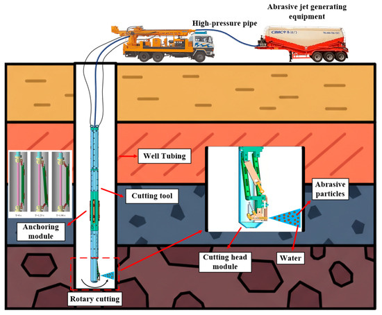
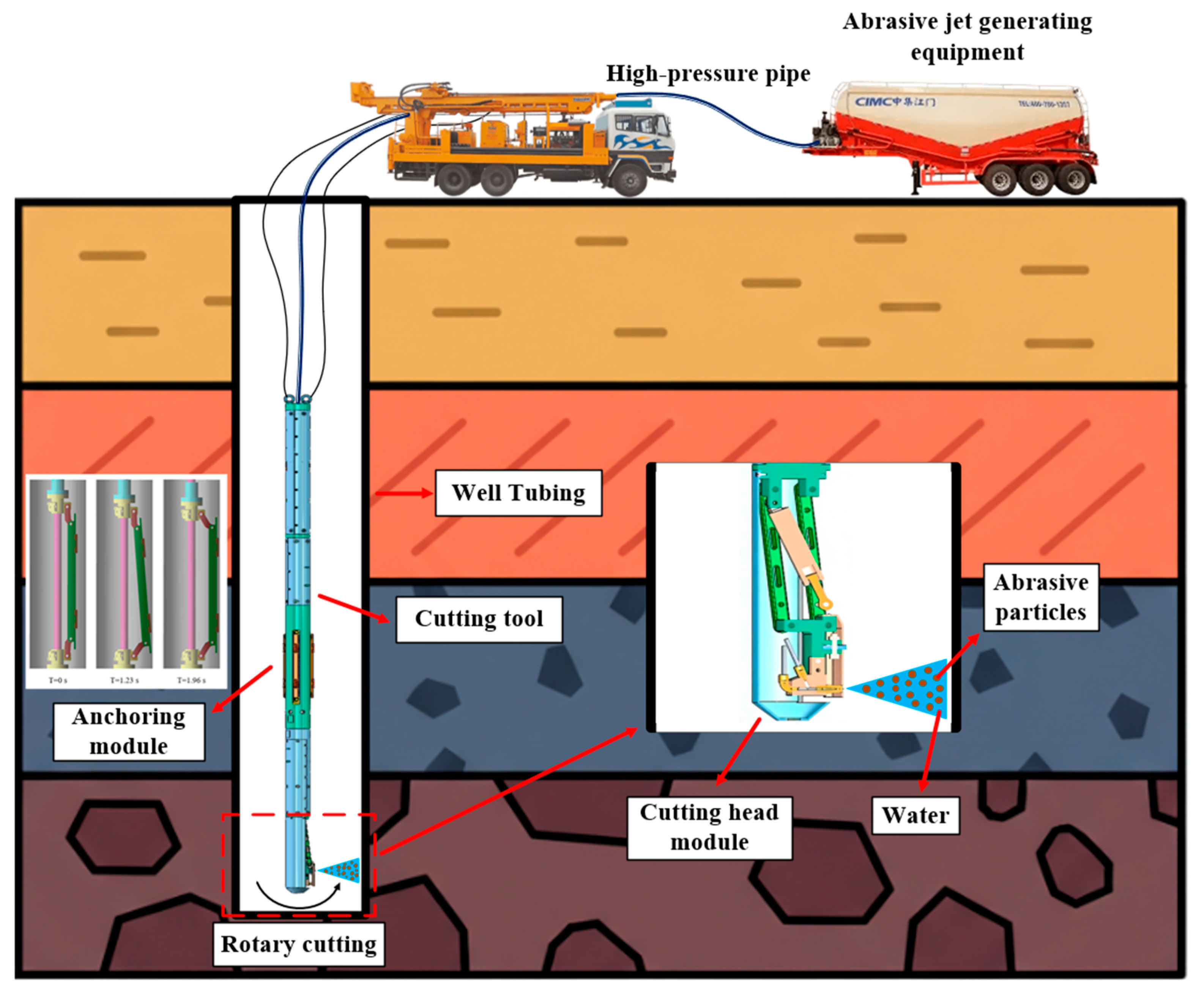
In downhole oil and gas cutting, AWJ cutting systems typically consist of an abrasive mixing system and an AWJ cutting tool. The mixing system of the AWJ cutting tool is typically installed at the surface, which limits its application in deep-well operations [18]. Long abrasive conveyance tubing is prone to severe erosive wear. In addition, the need for long-distance abrasive conveyance increases operational costs and raises the risk of tubing failure [19,20]. To address these issues, this study designs an integrated AWJ cutting tool that provides a novel solution for downhole rotary AWJ cutting (Figure 1). The tool features downhole abrasive mixing and conveyance, precise positioning, controllable peripheral speed, and stepless standoff distance adjustment.
Figure 1.
The questions of AWJ technology in casing cutting of oil and gas wells.
AWJ cutting has been widely applied in machining of metallic materials due to its high precision, flexibility, and absence of thermal damage [21]. Existing studies mainly focus on flat work pieces, and the optimization of process parameters under conventional cutting conditions has been relatively well established [7,22,23]. However, several research gaps still exist. First, limited attention has been paid to the rotational AWJ cutting of large-diameter thin-walled tubes, where the coupling effects of curved inner surfaces and rotational motion introduce additional complexity to the cutting process [3]. Second, most previous experimental designs are based on ideal static cutting environments while ignoring practical mechanical deviations in rotary operation, such as equipment eccentricity, radial run out, and installation coaxial errors [6,24,25]. The rationality of parameter matching and selection for actual rotary working conditions is rarely discussed in depth. Third, although the material removal mechanism of AWJ has been extensively investigated under linear cutting conditions, the underlying mechanism in rotational cutting remains unclear, particularly regarding the coordinated relationship between jet impact characteristics and thin-walled wall erosion damage [26,27].
To address these issues, this study designs an integrated rotary AWJ cutting tool to investigate tubing cutting performance under rotary AWJ impact. This study focuses on the novelty of damage-control mechanisms during the internal rotational cutting of thin-walled tubes. By incorporating assembly deviations and kinematic characteristics, it elucidates the criteria for optimal standoff distance selection under rotational conditions. Furthermore, the coupling effects between multiple process parameters, cutting quality, and erosion damage are uncovered. Finally, SPH-FEM numerical simulations are used to investigate the cutting mechanism, thereby underpinning the scientific validity and credibility of the findings.
2. Experiments and Methods
2.1. Experimental Setup and AWJ Tool
- (1)
- Experimental setup and control system
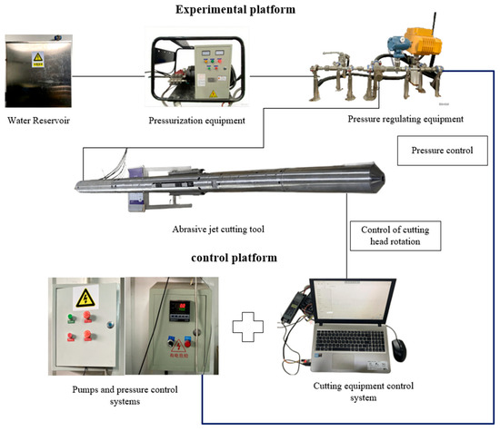
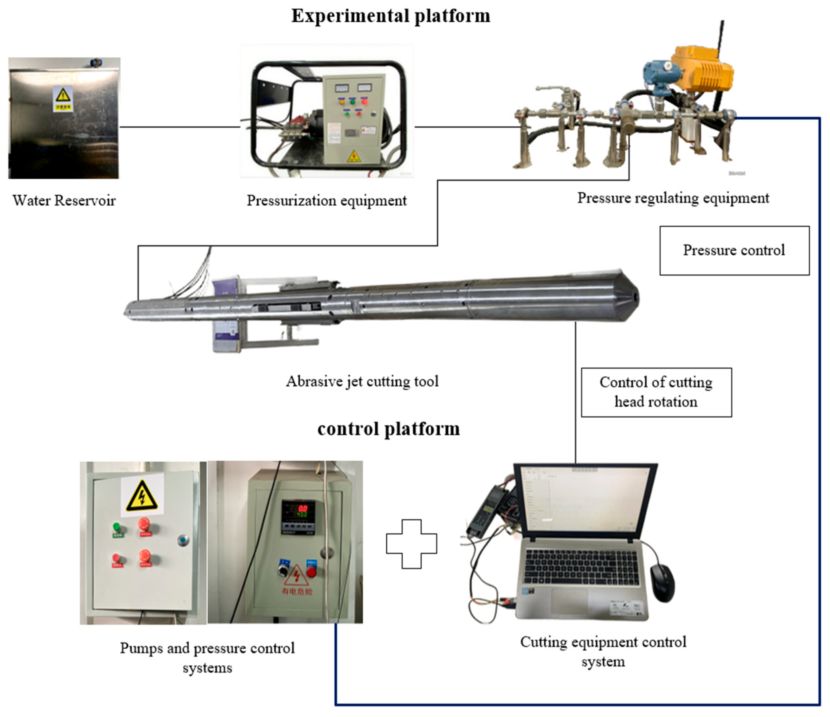
The experimental system consists of two main components: an experimental platform and a control platform. Specifically, the experimental platform consists of a water tank, a pressurization module, a pressure-regulating module, and an AWJ cutting tool, while the control platform consists of a pump and pressure control subsystem and a cutting tool control subsystem, as illustrated in Figure 2.
Figure 2.
AWJ cutting experimental system.
The cutting material is 6061 aluminum alloy tubing in three specifications: OD 150 mm × WT 2 mm.
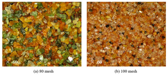
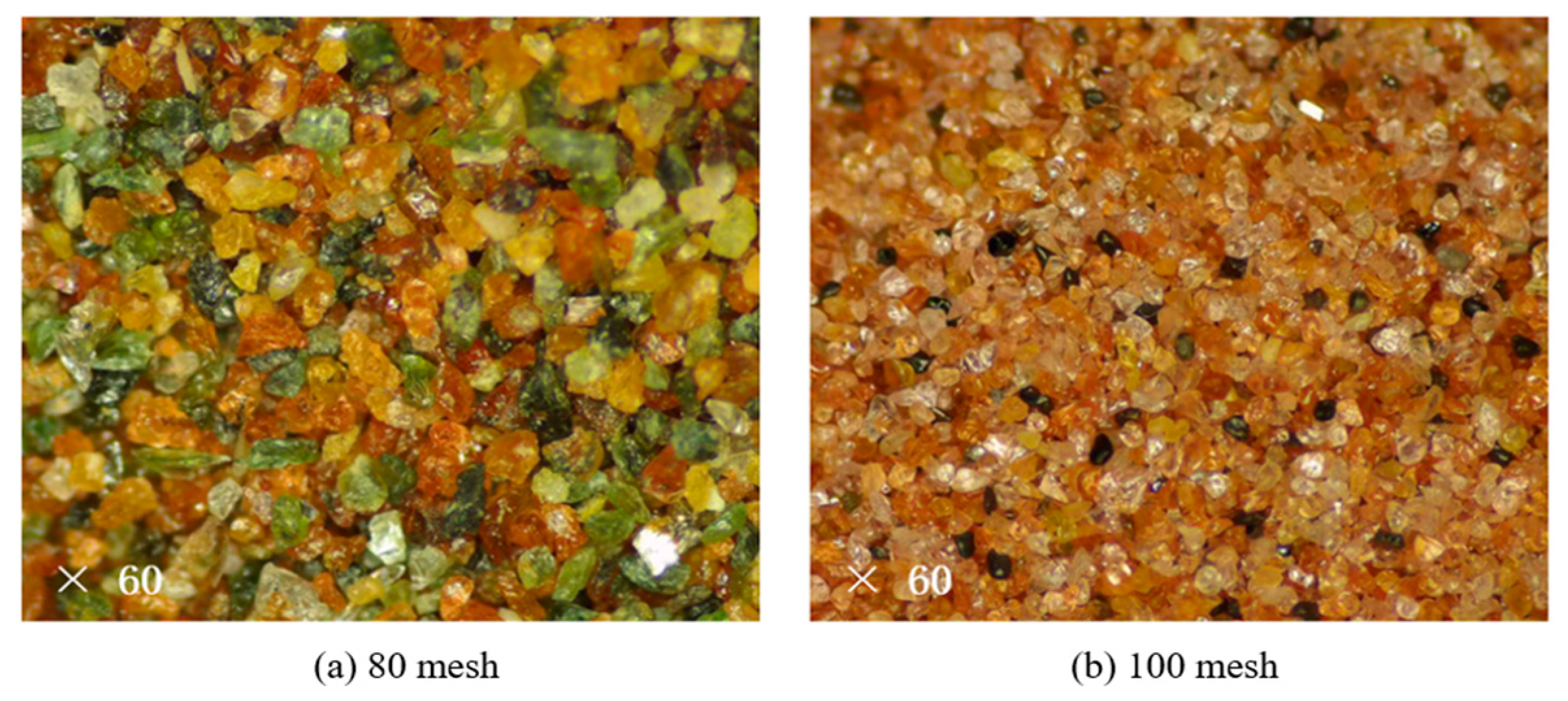
In downhole oil and gas operations, the wall thickness of active tubing typically ranges from 2.0 to 6.0 mm, with predominant specifications concentrated between 2.5 and 5.0 mm. The 2 mm thickness selected for this study represents the lower bound of engineering standards. Thin-walled tubing facilitates the observation of cutting penetration and kerf evolution, aligning with the requirements for mechanistic analysis and model validation. The optical micrographs in Figure 3 show the morphology of 80-mesh and 100-mesh abrasives at 60× magnification. The images reveal the particle size distribution and shape characteristics of the abrasives, which are key factors affecting the cutting performance of the AWJ system [27].
Figure 3.
Optical micrographs of abrasives with different mesh sizes.
- (2)
- AWJ velocity and pressure testing
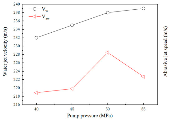
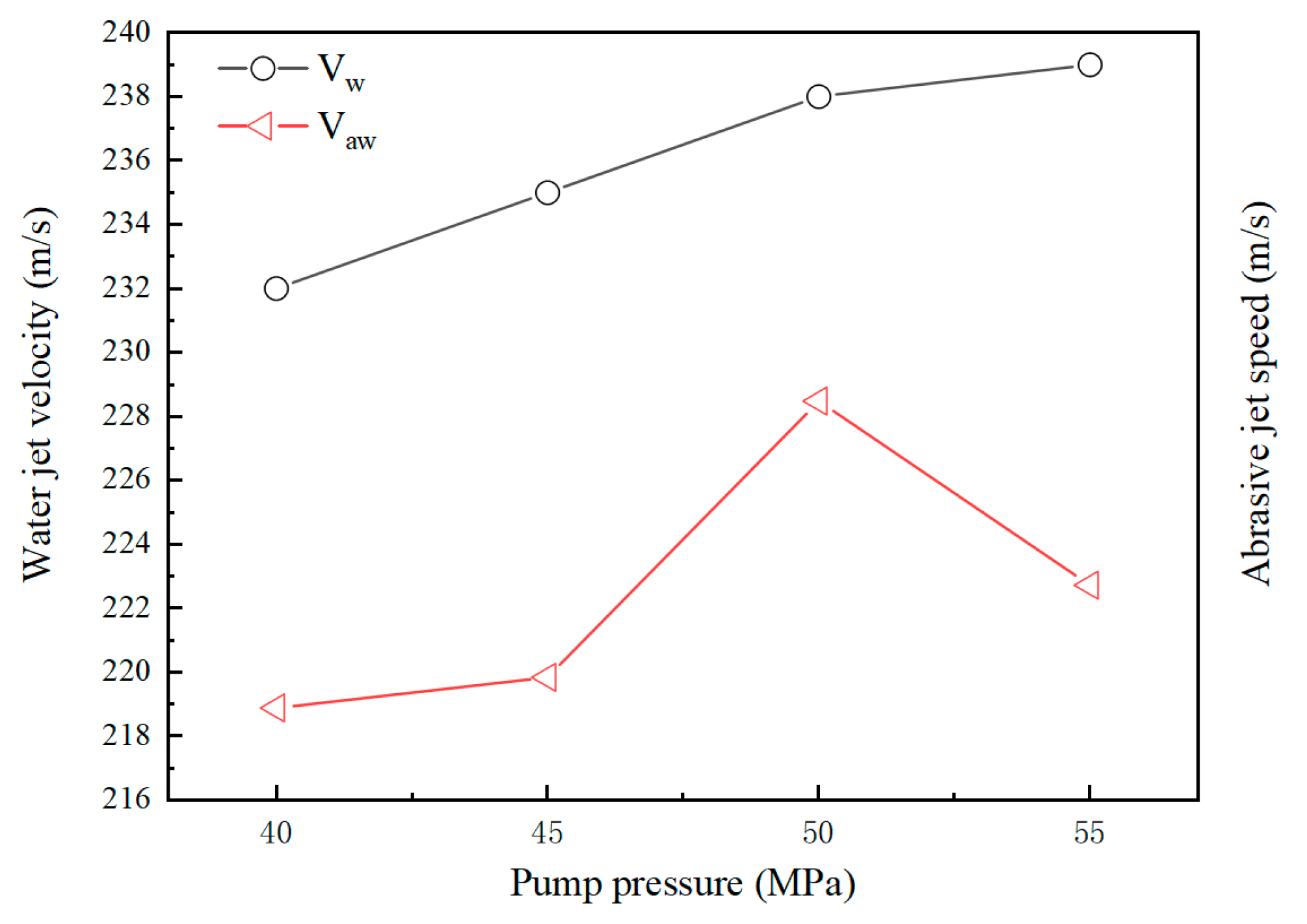
Since tubing geometry affected jet pressure and cutting efficiency, and the system can measure pump outlet pressure but not nozzle exit velocities, nozzle-exit velocity calibration was conducted to analyze the effect of jet velocity on cutting. The calibration sets the pump pressure P and jetting time T, measures the water-level difference h1 to obtain the water volume V, calculates the water velocity Vw = V/(TA), and then determines the AWJ velocity Vaw from momentum conservation, mwVw = (mw + ma)Vaw, as shown in Figure 4. The calculated Vaw exceeds the actual value because hydrodynamic and dynamic pressure losses are neglected [23]. As the pump pressure increases, the water-jet velocity Vw increases, whereas the AWJ velocity Vaw decreases from 50 to 55 MPa because of the higher abrasive feed rate (4.66 g/s at 50 MPa and 8.29 g/s at 55 MPa). An AWJ system featuring passive Venturi-based suction was used in this experiment without an active feeding device. Specifically, the abrasive particles are automatically entrained into the jet stream, driven by the vacuum effect generated within the mixing chamber by the high-pressure water jet. The abrasive feed rate increased from 4.66 g/s at 50 MPa to 8.29 g/s as the pressure rose to 55 MPa. This trend is consistent with the inherent physical laws governing passive entrainment AWJ. Consequently, this phenomenon serves as the primary reason for the decline in abrasive jet velocity (Vaw) as the pump pressure increases from 50 to 55 MPa. Specifically, an elevated abrasive mass fraction leads to a reduction in the mixed jet velocity, as dictated by the principle of conservation of momentum.
Figure 4.
Pump pressure and nozzle outlet velocity curve.
2.2. Self-Design AWJ Cutting Tool
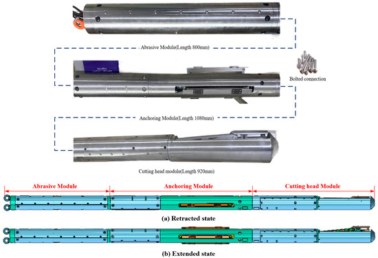
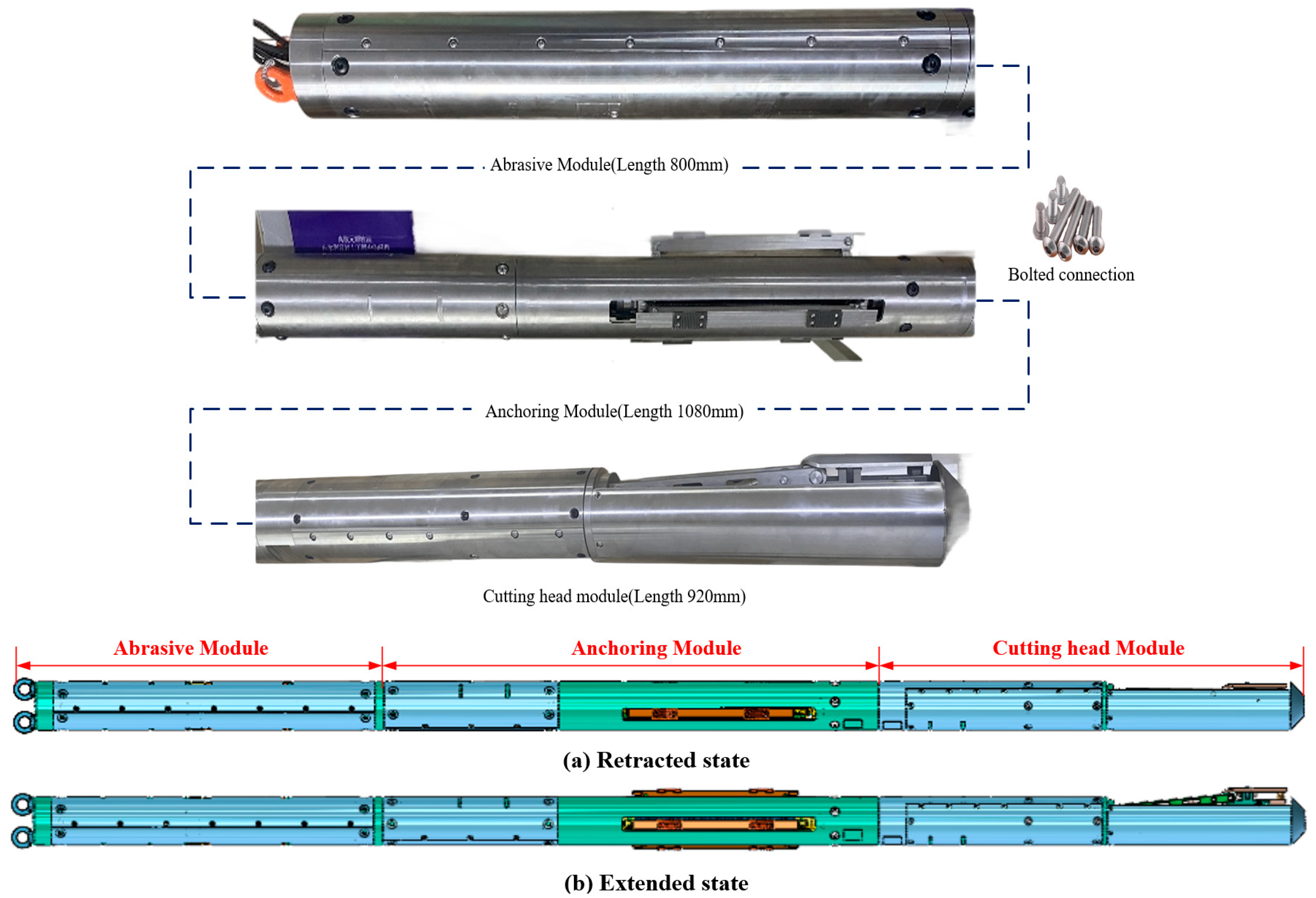
Figure 5 shows the AWJ cutting tool, which consists of three functional modules: an abrasive storage and conveyance module, an anchoring module, and a cutting head module. The tool has a total weight of 140 kg and an overall length of 2.8 m. The three modules have lengths of 800 mm, 1080 mm, and 920 mm, respectively. Specifically designed for cutting tubing with an inner diameter of 4.5–6.5 in., the proposed cutting tool offers the following three advantages over conventional tools: (1) Abrasive storage and conveyance module; unlike conventional abrasive mixing systems, this module uses downhole mixing through an integrated mixing system. It is equipped with a screw conveyor for abrasive transport, and the abrasive flow rate is controlled by adjusting the speed of a brushless DC motor. (2) Anchoring module: Instead of hydraulically actuated slips, which are prone to pressure fluctuations that reduce anchoring accuracy, this module uses an electric motor-driven ball screw-nut mechanism. This configuration enables precise control of the screw peripheral speed, thereby achieving accurate anchoring. (3) Cutting head module: This module can achieve precise control of peripheral speed and continuous adjustment of standoff distance, which are two critical parameters governing cutting performance. Conventional systems typically rely on jet-driven cutting head rotation, which is constrained by high-viscosity oil; friction rings limit precise speed control. To address these issues, a hydraulic cylinder is used to achieve indirect continuous adjustment of the standoff distance.
Figure 5.
Rotary AWJ cutting tool.
2.3. Experimental Program
A single-factor design was used to investigate the effects of individual parameters on cutting performance. Because 360° circumferential cutting of aluminum alloy tubes is time-consuming, and the cutting performance of full-circumference and segmented cutting is equivalent, segmented cutting was adopted. Since a single pass could not fully penetrate the tube wall, a cyclic cutting strategy was implemented, with each cycle consisting of 3.5 cumulative effective cutting strokes. The cyclic process was as follows: after the AWJ penetrated the tube wall at the initial cutting location, the nozzle motor rotated forward for 10 s and then reversed for 10 s to return to the initial cutting location.
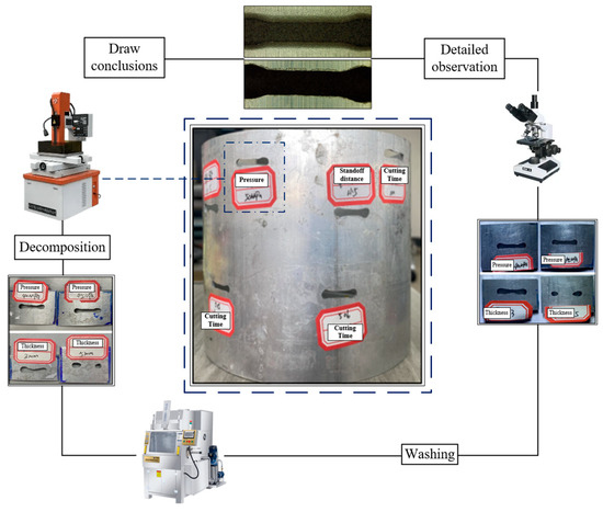
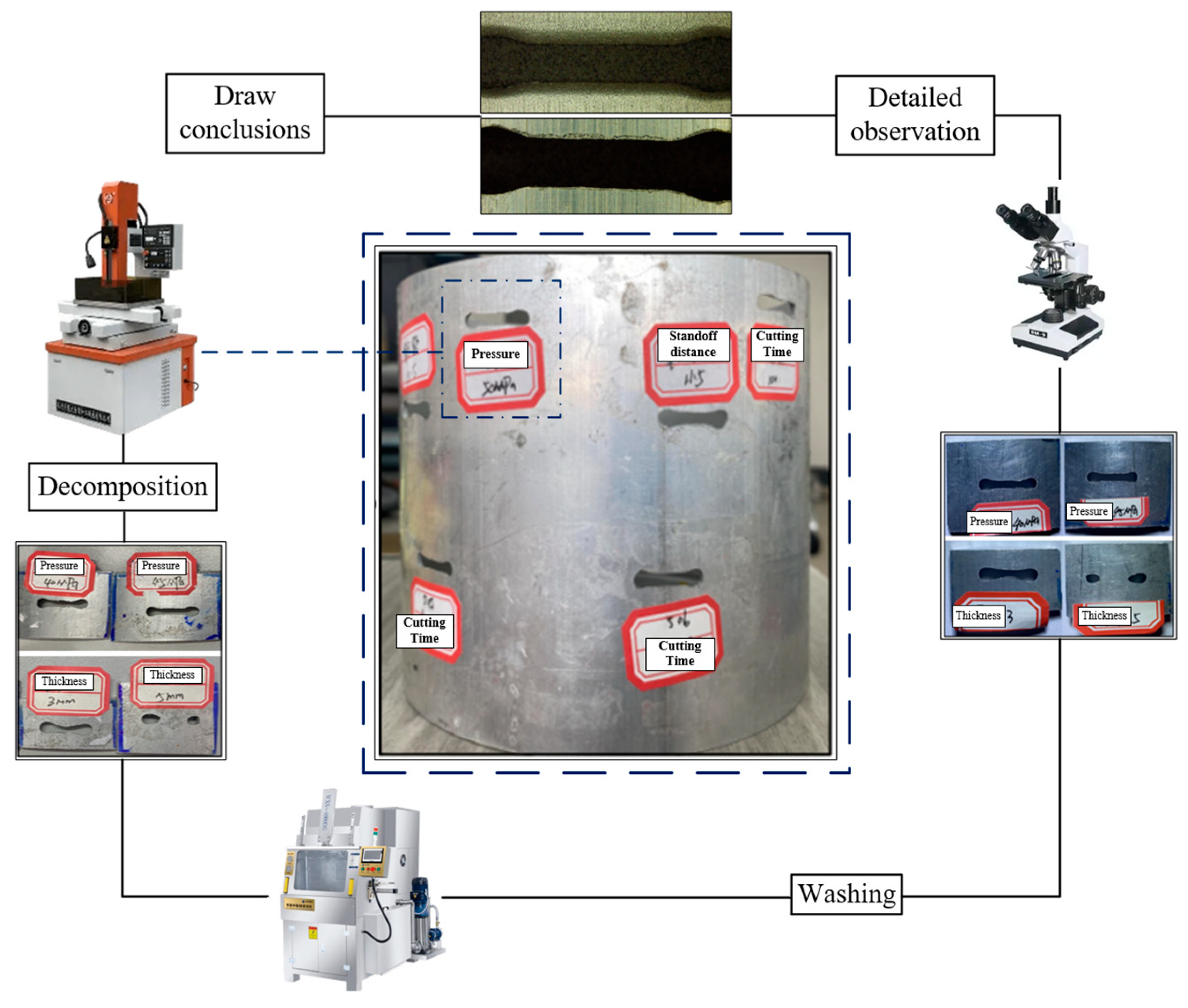
After the experiment, the tube was disassembled for microscopic measurement of kerf geometry and observation of surface morphology (Figure 6). The samples were sectioned to enable microscopic examination of their cross sections. For each sample, kerf width and depth were measured. For fully penetrated samples, the bottom kerf width was measured at equally spaced points aligned with the top measurement points, and the kerf depth was taken as the tube wall thickness. For unpenetrated samples, the kerf width and depth were measured using negative replicas prepared with moldable silicone.
Figure 6.
Column slice sampling.
The influence of five key process parameters, peripheral speed, pump pressure, standoff distance, cutting time, and abrasive mesh size, on AWJ cutting performance was experimentally investigated. The experimental conditions and their respective levels are detailed in Table 1. To ensure reproducibility, each experimental condition was conducted in triplicate. Error intervals were determined based on the standard deviation of the triplicate measurements.
Table 1.
AWJ cutting experiment plan.
3. Cutting Mechanism
The tubing is modeled using the finite-element method (FEM) at full scale, with an outer diameter of 150 mm and a wall thickness of 2 mm, consistent with the experimental specimens (Table 2). The AWJ simulation uses smoothed particle hydrodynamics (SPH) in two ways: direct particle generation within the solver and SPH conversion of imported pre-meshed geometries. The numerical model includes both the AWJ and the tubing, with the water and abrasive phases represented by SPH particles [28,29]. The SPH-FEM coupling formulation is presented in detail in Appendix A.
Table 2.
Setting parameters for the state equations of water and abrasives.
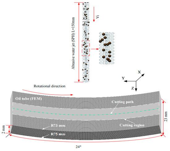
To improve computational efficiency, a 1/15 circumferential segment of the full tube was modeled for the simulations, and the specific model parameters are shown in Figure 7.
Figure 7.
SPH-FEM coupled model.
Water is modeled using the NULL model, and its pressure P is calculated using the Mie-Grueisen equation of state with the following Equation (1):
where ρ0 is the density of water, γ0 is the Grueisen coefficient, S1 to S3 are the fitting coefficients, a is the volume correction factor, C is the speed of sound, μ is Poisson’s ratio, and E is Young’s modulus [30].
The abrasive is modeled as NULL, and its pressure is chosen to be calculated by the LINEAR_POLYNOMIAL equation of state, shown in Equation (2):
where C0~C6 are equation of state constants, μ is Poisson’s ratio, and E is Young’s modulus [31].
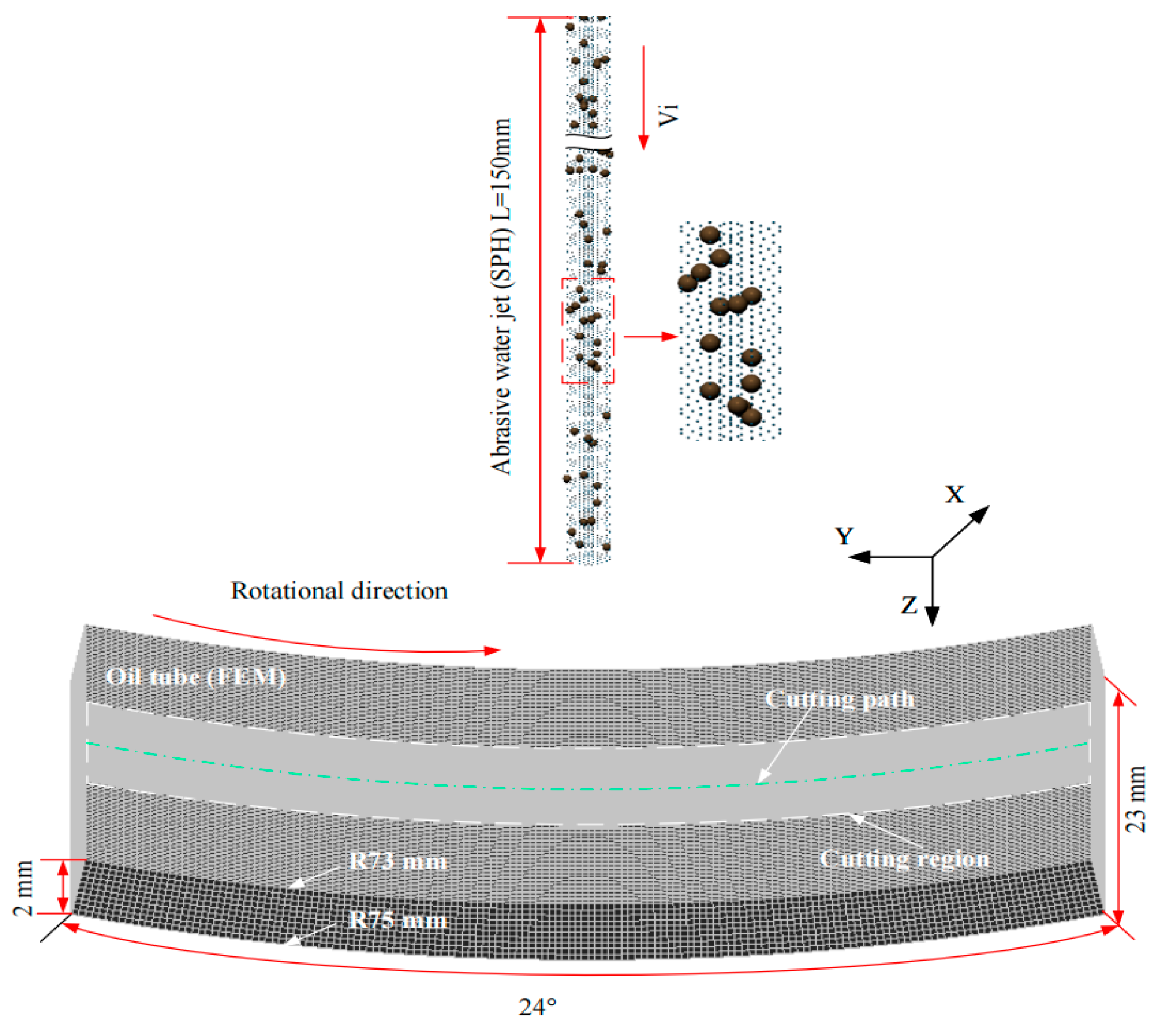
Mesh size significantly influences numerical accuracy; finer meshes enhance solution accuracy but raise computational cost and the risk of exceeding hardware limits, whereas coarser meshes reduce solution quality. An optimal mesh design balances element density, computational cost, and solution accuracy [32]. Deviations in kerf width and depth between simulations and experimental data at 50 MPa were used to determine an appropriate mesh resolution.
Figure 8 shows that the simulated kerf width exhibits minimal mesh dependence, whereas the kerf depth is highly sensitive to mesh size. The model with 165,371 elements predicted a kerf depth of 1.11 mm (a deviation of 0.43 mm from the experimental value of 0.68 mm). When the number of elements was increased to 272,811–322,811, the predicted depth converged, so the mesh with 272,811 elements was selected for subsequent simulations.
Figure 8.
Grid independence verification.
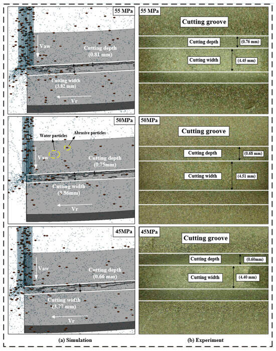
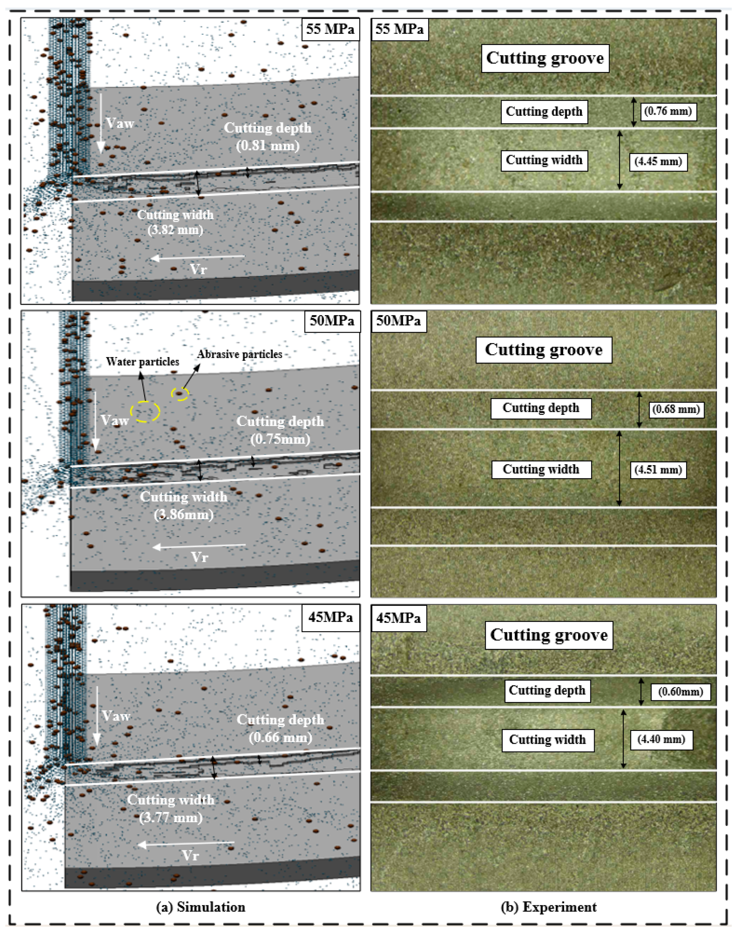
Figure 9 compares the experimental and simulated cutting results at three pump pressures (45, 50, and 55 MPa). For all conditions, the relative errors between simulation and experiment for cutting width (14.16–14.41%) and cutting depth (6.58–10.29%) are within an acceptable range. The model also accurately captures the key trends of cutting width peaking at 50 MPa and cutting depth increasing with pump pressure, validating its reliability for rotary AWJ cutting prediction.
Figure 9.
Comparison of cutting depth and width between experiment and simulation.
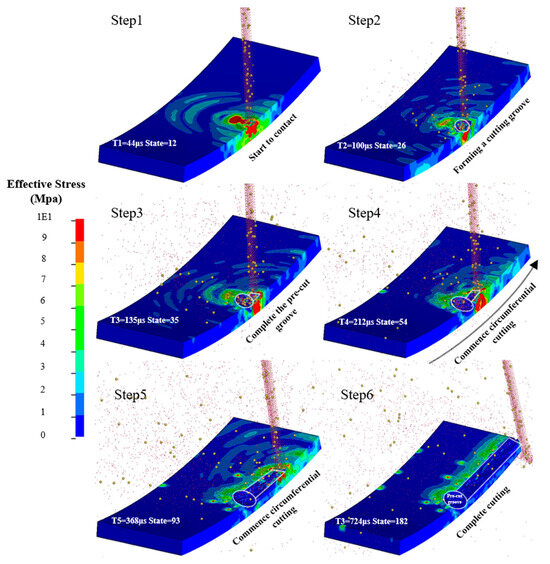
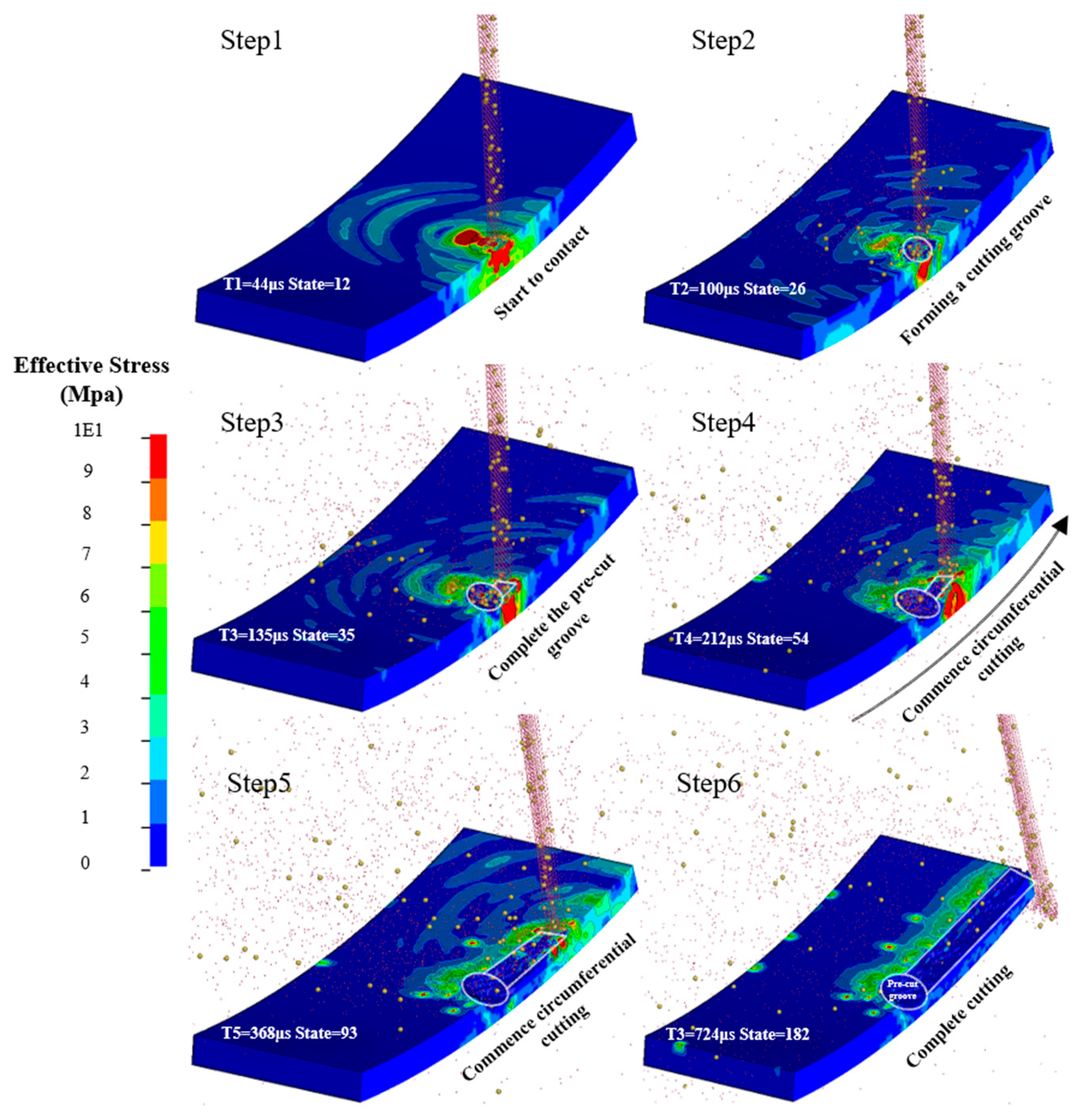
Given the limitations of the experimental parameters, the SPH-FEM coupled approach is used to extend the study of rotary AWJ cutting mechanisms. Notably, 2 mm-thick tubes are subjected to cyclic cutting in the experiments to visualize penetration, whereas the simulations use single cuts because of implementation constraints. However, circumferential cutting can be regarded as the nonlinear accumulation of single cuts, so the conversion methodology is not affected [33]. Accordingly, a 50 MPa single-cut validation test was carried out using 80-mesh abrasive, a standoff distance of 8.5 mm, a peripheral speed of 5.65 mm/s, a 0.5 mm water nozzle and a 2 mm abrasive nozzle, a cutting time of 10 s, a wall thickness of 2 mm, and an abrasive concentration of 5.4% (the ratio of the abrasive mass flow rate to the total mass flow rate of the mixed jet, Equation (3)), with water as the working medium. The numerical results were compared with the measured kerf depth and width. The kerf formation process is shown in Figure 10.
Figure 10.
Rotary AWJ cutting process.
As shown in Figure 10, the high-energy rotary AWJ first impinges on the tubing surface at high velocity, forming an initial kerf through kinetic energy transfer and the impact–erosion action of abrasive particles. Subsequently, as the cutting tool rotates circumferentially, the jet continuously sweeps along the tubing’s circumference, gradually increasing the kerf depth in the radial direction while extending it axially. Owing to the relatively uniform jet energy distribution, the kerf morphology remains essentially uniform. Finally, through continuous circumferential feed and cumulative energy input, the kerf ultimately achieves full circumferential continuity, thereby completing circumferential cutting of the tubing.
4. Results
4.1. Effect of Peripheral Speed on Cutting Performance
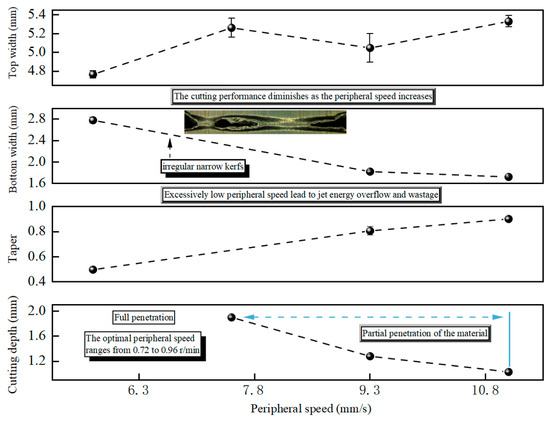
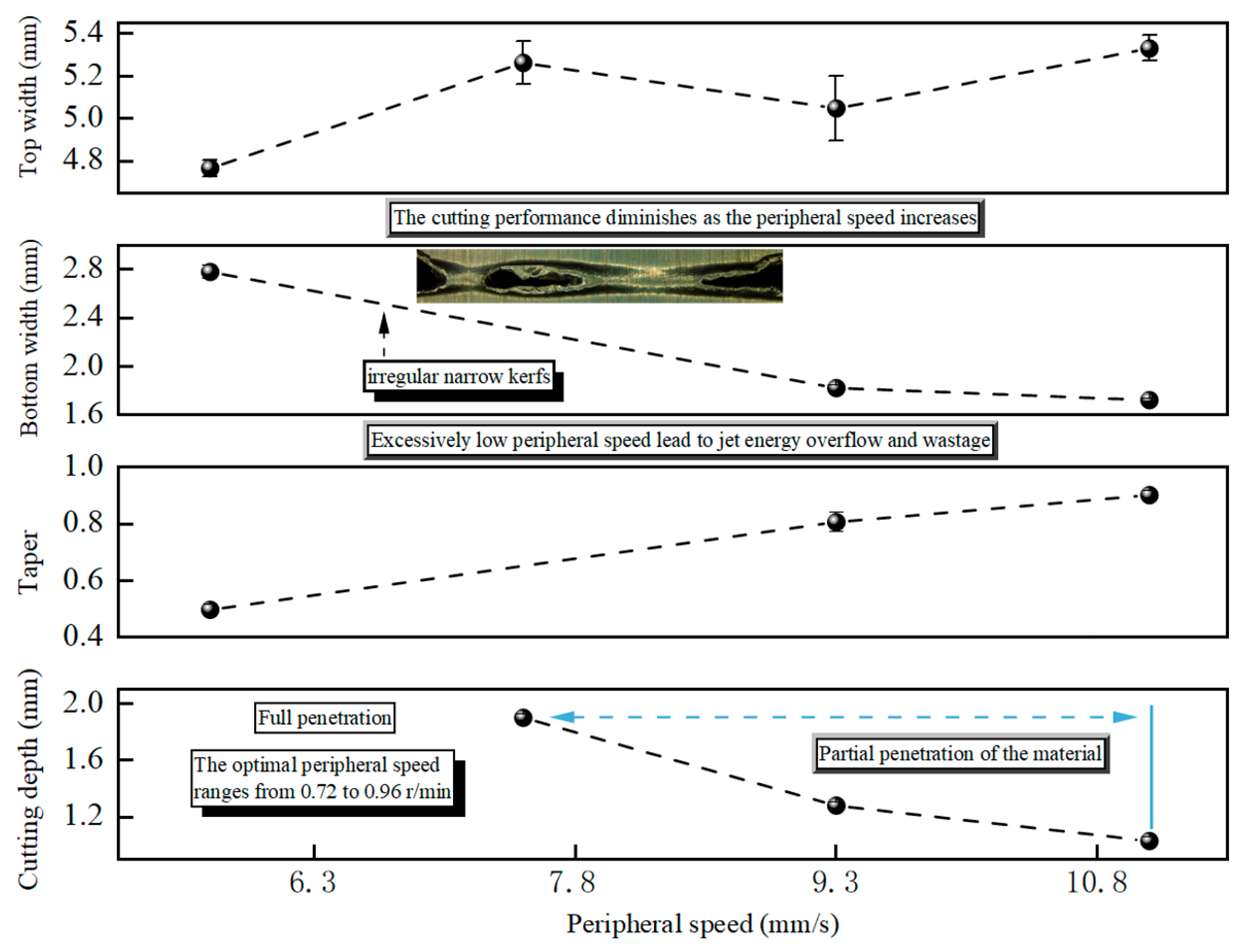
Figure 11 shows the effect of peripheral speed on kerf parameters. All data are presented with error bars denoting the standard deviation of three independent replicate tests, providing a measure of experimental repeatability.
Figure 11.
Effect of peripheral speed on kerf parameters at a pump pressure of 50 MPa, a cutting time of 70 s, an abrasive mesh size of 80, a standoff distance of 8.5 mm, and an abrasive mass fraction of 5.48% (±2.02%).
Regarding top kerf width, the data exhibited a fluctuating trend with increasing peripheral speed, reaching a maximum at 7.8 mm/s. Significant overlap of error bars across most tested speed levels indicated no statistically significant differences between groups. One-way ANOVA further verified that peripheral speed exerted no significant effect on top kerf width (p = 0.18).
In contrast, bottom kerf width decreased monotonically as peripheral speed increased. Non-overlapping error bars between low and high peripheral speed levels confirmed the statistical significance of this trend, which was further validated by one-way ANOVA (p < 0.001).
Kerf taper exhibited a steady, increasing trend with rising peripheral speed. The non-overlapping error bars across most tested speed levels indicated that the increase was statistically significant, as supported by one-way ANOVA results (p < 0.001).
Cutting depth decreased sharply with increasing peripheral speed, transitioning from full penetration at low speeds to partial penetration at higher speeds. The clear separation of error bars between the full and partial penetration regimes, combined with one-way ANOVA results (p < 0.001), confirmed that peripheral speed had a highly significant negative effect on cutting depth.
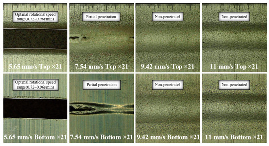
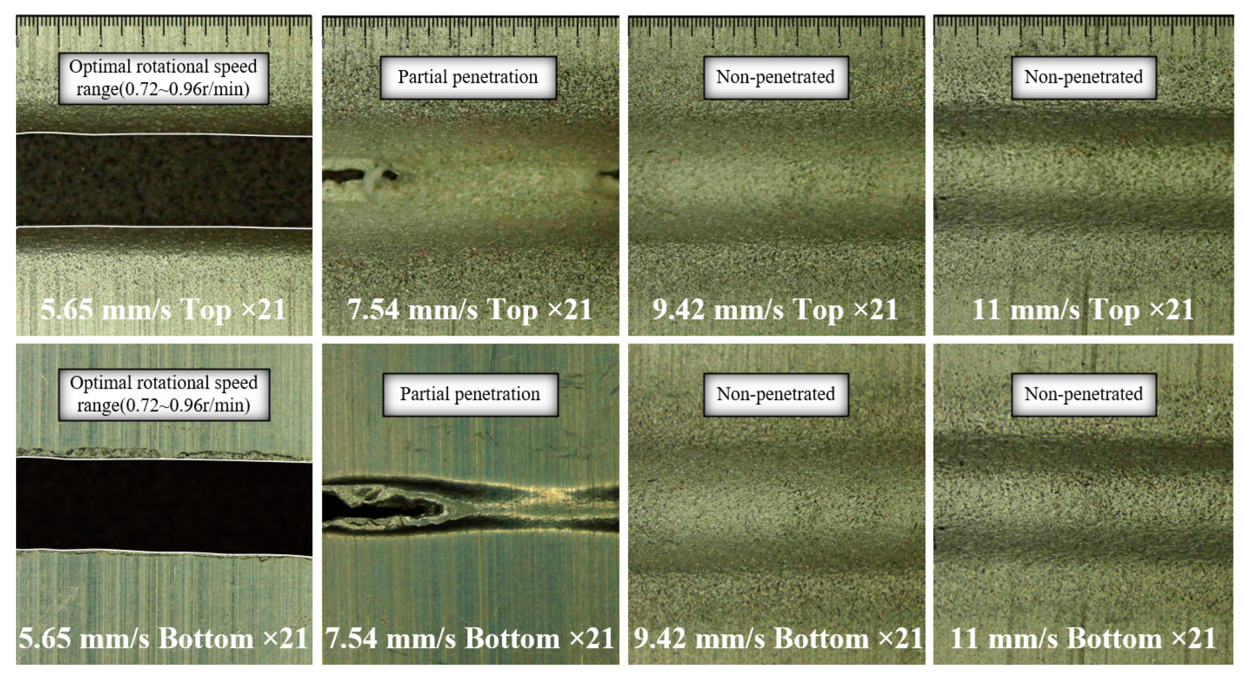
As the peripheral speed increases, the interaction between abrasive particles and the standoff material decreases, which lowers material removal efficiency and reduces cutting depth. Peripheral speed has a significant effect on the cutting performance of rotary AWJ cutting. Specifically, full material penetration is achieved at a low peripheral speed of 5.65 mm/s, but the cutting efficiency remains low, and part of the jet energy is unnecessarily consumed. As the peripheral speed increases to 7.54 mm/s, the jet initiates partial penetration of the tube and produces irregular narrow kerfs on the tube’s inner surface of the tube. Because of the severe material deformation at the kerf bottom, the kerf width at the bottom cannot be reliably measured. Figure 12 shows pronounced material deformation at the kerf’s bottom, which explains why the bottom kerf width shown in Figure 11 cannot be measured. At a peripheral speed of 9.42 mm/s, the decrease in cutting depth slows, and the cutting depth is 1.28 mm. When the peripheral speed is further increased to 11 mm/s, the cutting depth decreases to 1.03 mm, corresponding to a reduction of 0.25 mm.
Figure 12.
Kerf morphology at different peripheral speeds.
Overall, peripheral speed exerted a highly significant influence on bottom kerf width, kerf taper, and cutting depth, while its effect on top kerf width was not statistically significant. The optimal peripheral speed identified in this study ranges from 5.65 to 7.54 mm/s. This range not only avoids low efficiency and excessive energy consumption caused by excessively low peripheral speeds but also prevents incomplete penetration due to excessively high peripheral speeds.
4.2. Effect of Pump Pressure on Cutting Performance
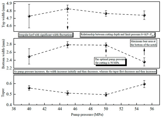
Figure 13 shows the effect of pump pressure on kerf parameters. All data are presented with error bars denoting the standard deviation of three independent replicate tests, providing a measure of experimental repeatability.
Figure 13.
Effect of pump pressure on kerf parameters at a peripheral speed of 5.65 mm/s, a cutting time of 70 s, an abrasive mesh size of 80, a standoff distance of 8.5 mm, and an abrasive mass fraction of 5.82% (±1.68%).
An optimal cutting pressure exists because material fracture requires a threshold pressure, and the cutting depth exhibits a strong dependence on pressure. Specifically, the relationship between cutting depth and the material fracture threshold is expressed as follows [34]:
where h is the cutting depth, k is the coefficient, P is the jet pressure, and Pthr is the pressure threshold value.
Equation (4) indicates that sub-threshold pressures fail to remove surface material, whereas excessive pressures result in severe wear of the nozzle and flow paths. Additionally, constraints on nozzle diameter exacerbate interparticle interference and compaction, thereby promoting abrasive fragmentation and degrading cutting efficiency.
In terms of top kerf width, the data presented a non-monotonic variation with pump pressure and reached the maximum at 45 MPa. Owing to high data variability, as reflected by the broad error bars at 40 MPa, the error ranges overlapped obviously among all pressure groups. One-way ANOVA results further verified that pump pressure exerted no statistically significant influence on top kerf width (p = 0.12). This demonstrates that the minor data fluctuations stemmed from random experimental errors instead of the inherent regulation of pumping pressure.
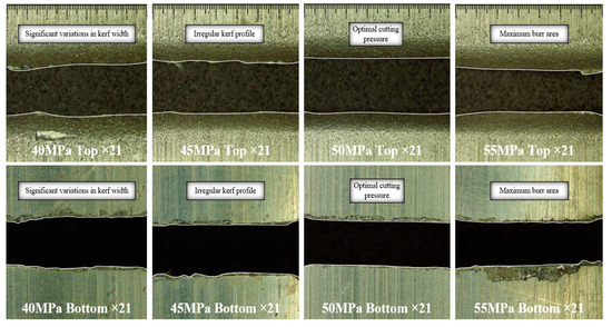
In contrast, the bottom kerf width showed an obvious trend of initial rise and subsequent decline. It maintained a stable plateau at approximately 2.8 mm within 50 MPa, followed by a sharp reduction at 55 MPa. The non-overlapping error bars between the plateau stage and extreme pressure conditions (40 MPa and 55 MPa) demonstrated the statistical significance of this variation, as further verified by one-way ANOVA analysis (p < 0.001). The maximum value of bottom kerf width appeared at 50 MPa, which aligned well with the recommended optimal pump pressure determined for rotary AWJ cutting (Figure 14).
Figure 14.
Kerf morphology under different pump pressures.
For the kerf taper, its values first decreased to a minimum at 46–50 MPa and then increased at 55 MPa. No overlap of error bars was observed between the low-taper range (46–50 MPa) and extreme pressure levels (40 MPa and 55 MPa). Furthermore, one-way ANOVA results confirmed that pump pressure exerted a highly significant effect on kerf taper (p < 0.001). The low kerf taper values at 46–50 MPa indicated relatively uniform kerf geometry, whereas the increase at 55 MPa suggested uneven energy distribution along the jet path (Figure 14).
At a pump pressure of 55 MPa, the system’s passive suction mechanism generates a robust vacuum within the mixing chamber. This configuration facilitates an enhanced suction vacuum, which significantly boosts the abrasive entrainment efficiency. Consequently, the abrasive entrainment efficiency is significantly improved. At this specific pressure, the abrasive feed rate reaches a peak that substantially exceeds values at lower pressures, resulting in a higher abrasive mass fraction. Based on the principle of momentum conservation, the subsequent intensified inter-particle collisions and suppressed the lateral expansion of the jet. This confinement narrows the effective impact area during jet propagation, ultimately leading to a reduced kerf width. Furthermore, excessive pressure induces violent internal collisions during mixing, causing abrasive fragmentation into smaller particles. Consequently, the diminished erosive capacity of these small particles results in a further decrease in cutting width.
Overall, pump pressure significantly influenced bottom kerf width and taper, but not top kerf width. The recommended optimal pump pressure of 50 MPa balances cutting width and uniformity, minimizing taper while maximizing effective penetration.
4.3. Effect of Standoff Distance on Cutting Performance
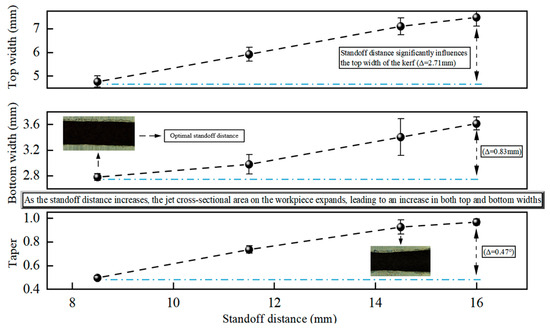
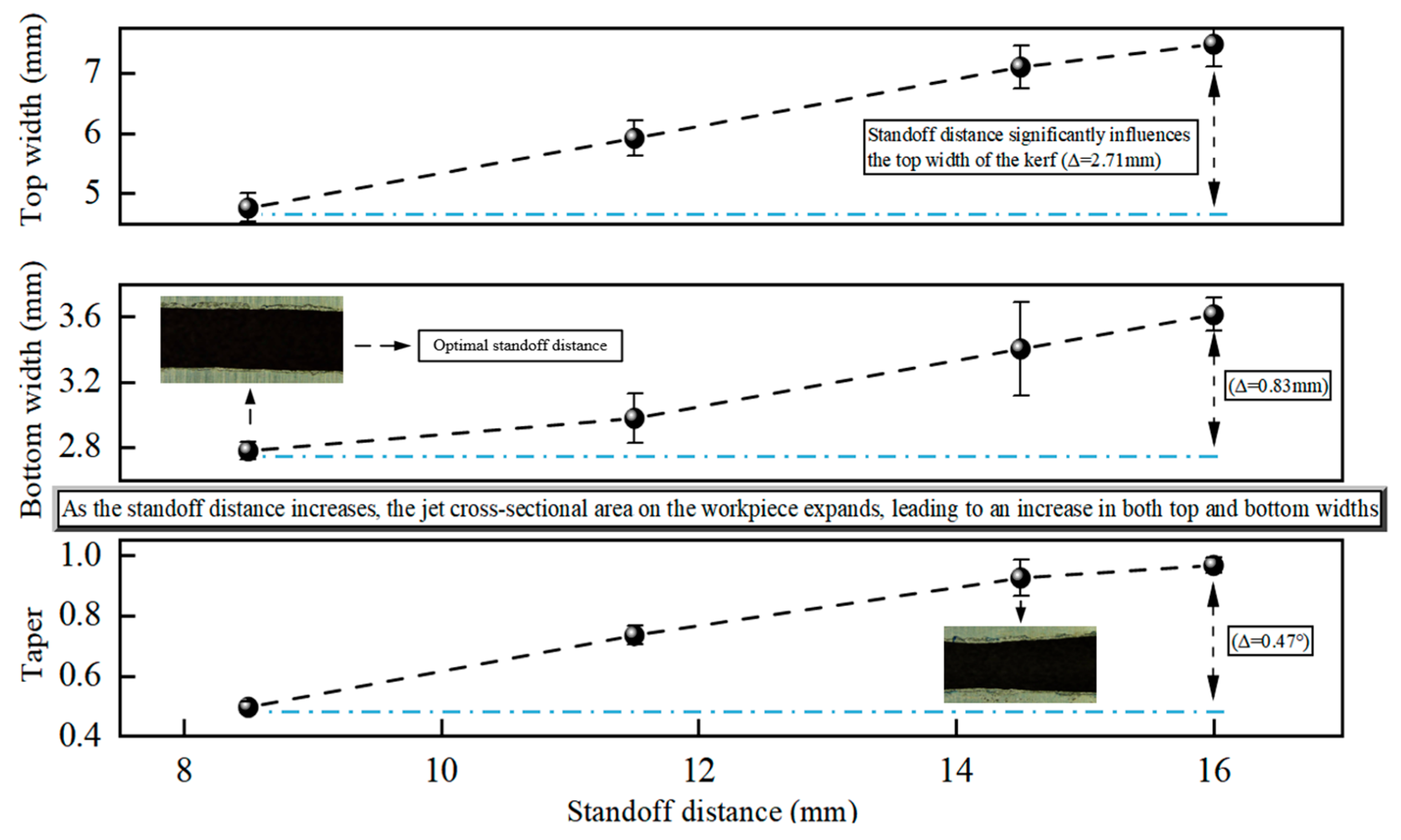
Figure 15 shows the effect of standoff distance on kerf parameters. All data are presented with error bars denoting the standard deviation of three independent replicate tests, providing a measure of experimental repeatability.
Figure 15.
Effect of standoff distance on kerf parameters at a peripheral speed of 5.65 mm/s, a cyclic cutting time of 70 s, a pump pressure of 50 MPa, an abrasive mesh size of 80, and an abrasive mass fraction of 5.48% (±2.02%).
For conventional flat-plate AWJ cutting, a small standoff distance of approximately 2 mm is widely applied to concentrate jet energy and improve cutting efficiency. However, a relatively large standoff distance was adopted in this study, restricted by the structural features of large-diameter thin-walled tubes and the unique operating conditions of rotary AWJ cutting. An overly small standoff distance leads to highly concentrated jet energy, which easily causes local over-erosion and surface damage to the pipe inner wall. Moreover, rotary cutting inevitably involves mechanical deviations such as eccentricity, radial run out and installation coaxiality errors. Insufficient standoff distance may result in collision between the high-speed rotating nozzle and the tube wall, further causing nozzle damage and equipment failure. In this regard, the standoff distance in the experiment was determined to balance cutting performance and operational safety.
For top kerf width, values increased monotonically with standoff distance, rising from approximately 4.9 mm at 8 mm to 7.3 mm at 16 mm. The non-overlapping error bars across most tested standoff distances indicated that the observed increase was statistically significant. One-way ANOVA confirmed that standoff distance exerted a highly significant effect on top kerf width (p < 0.001), consistent with the jet expansion mechanism: longer standoff distances allow the abrasive water jet to spread, while the cross-sectional area of the jet impinging on the workpiece increases.
Similarly, bottom kerf width exhibited a steady increasing trend with standoff distance from about 2.8 mm at 8 mm to 3.6 mm at 16 mm. While partial overlap of error bars was observed at intermediate distances (12 mm and 14 mm), the clear separation of error bars between the extreme values (8 mm and 16 mm) confirmed that the overall trend was statistically significant. ANOVA results further validated that standoff distance significantly influenced bottom kerf width (p < 0.001), as the expanding jet maintains higher kinetic energy at the cutting front over a longer distance.
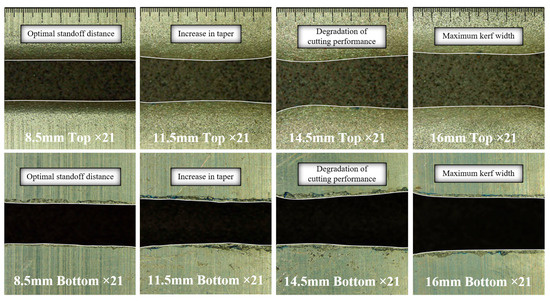
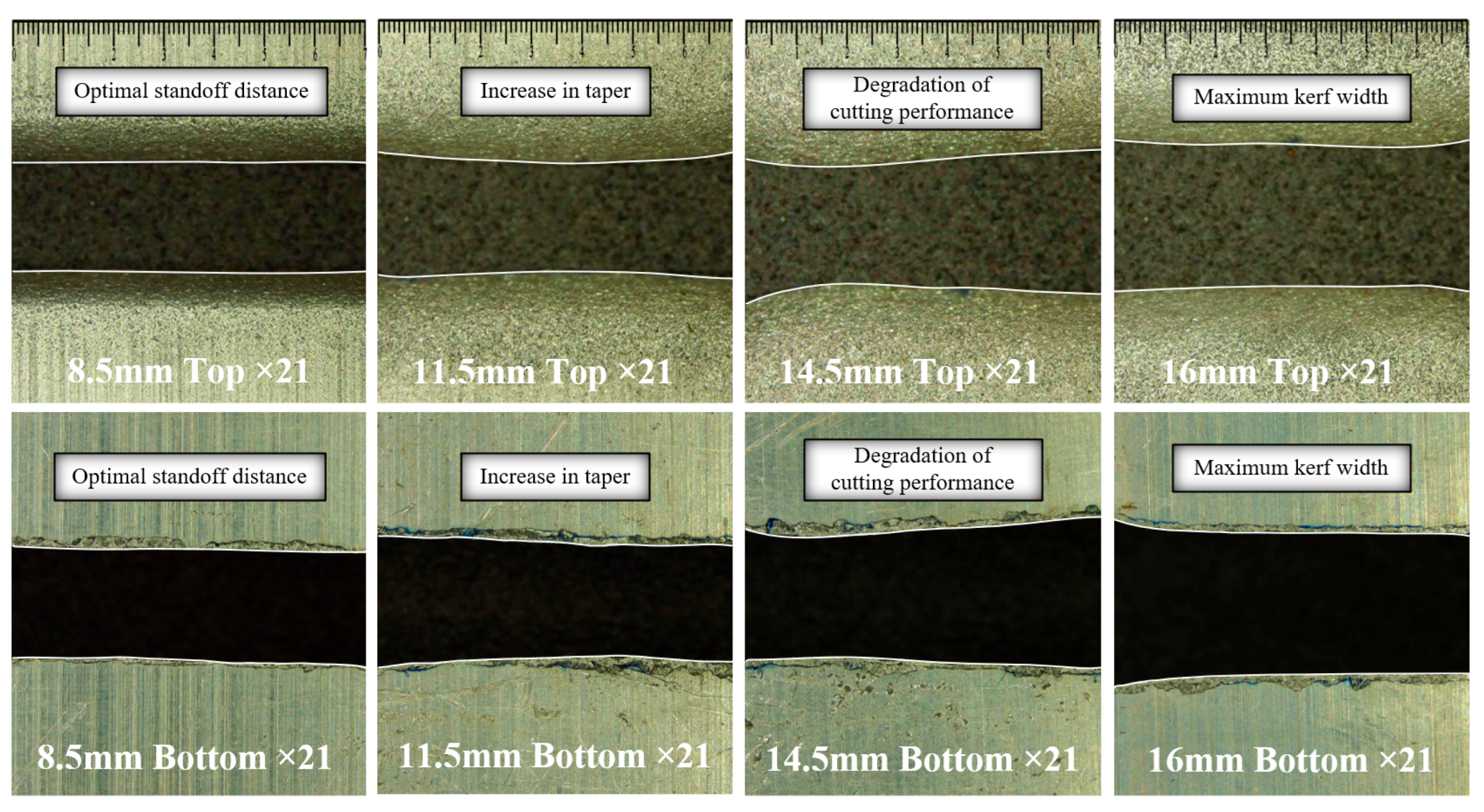
For kerf taper, values increased linearly with standoff distance from about 0.5 at 8 mm to 1.0 at 16 mm. The non-overlapping error bars across all tested distances indicated a highly significant trend, which was supported by one-way ANOVA (p < 0.001). The increasing taper reflects the growing discrepancy between top and bottom kerf widths: the jet expands significantly at the surface while still penetrating the material, leading to a wider kerf at the top relative to the bottom (Figure 16).
Figure 16.
Kerf morphology at different standoff distances.
Overall, standoff distance had a highly significant effect on all three kerf geometry parameters. The optimal standoff distance of 8.5 mm (indicated in Figure 16) balances sufficient jet expansion for effective cutting with minimal taper, ensuring uniform kerf geometry and efficient material removal.
4.4. Effect of Cutting Time on Cutting Performance
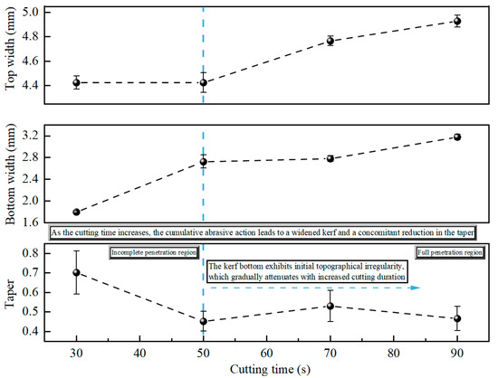
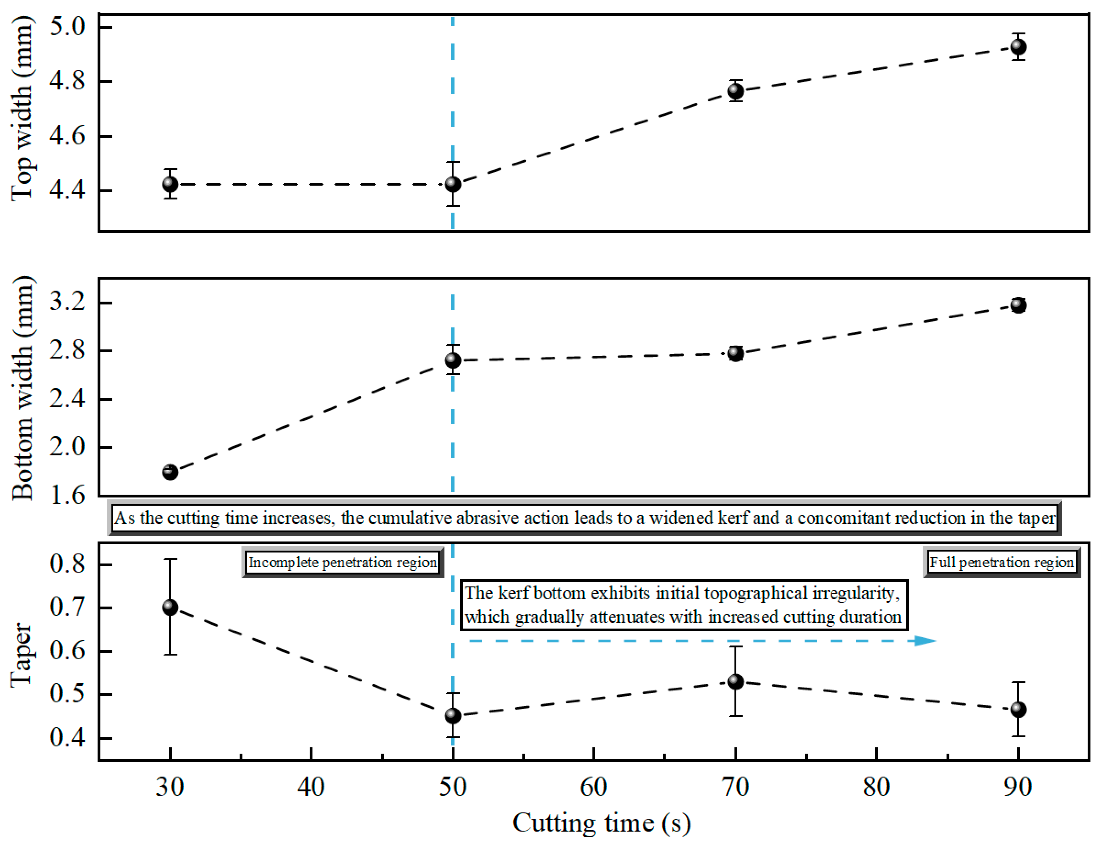
Figure 17 shows the effect of cutting time on kerf parameters. All data are presented with error bars denoting the standard deviation of three independent replicate tests, providing a measure of experimental repeatability.
Figure 17.
Effect of cutting time on kerf parameters at a peripheral speed of 5.65 mm/s, an abrasive mesh size of 80, a pump pressure of 50 MPa, a standoff distance of 8.5 mm, and an abrasive mass fraction of 6.02% (±1.48%).
For top kerf width, values remained nearly constant at about 4.4 mm between 30 s and 50 s, then increased monotonically with further cutting time, reaching 4.9 mm at 90 s. Overlapping error bars between 30 s and 50 s indicated no statistically significant difference in this stage. In contrast, non-overlapping error bars between the pre-50 s and post-70 s groups confirmed the increasing trend was statistically significant. One-way ANOVA further verified that cutting time exerted a highly significant effect on top kerf width (p < 0.001), consistent with cumulative abrasive erosion at the jet entrance over extended durations.
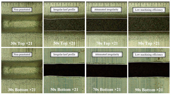
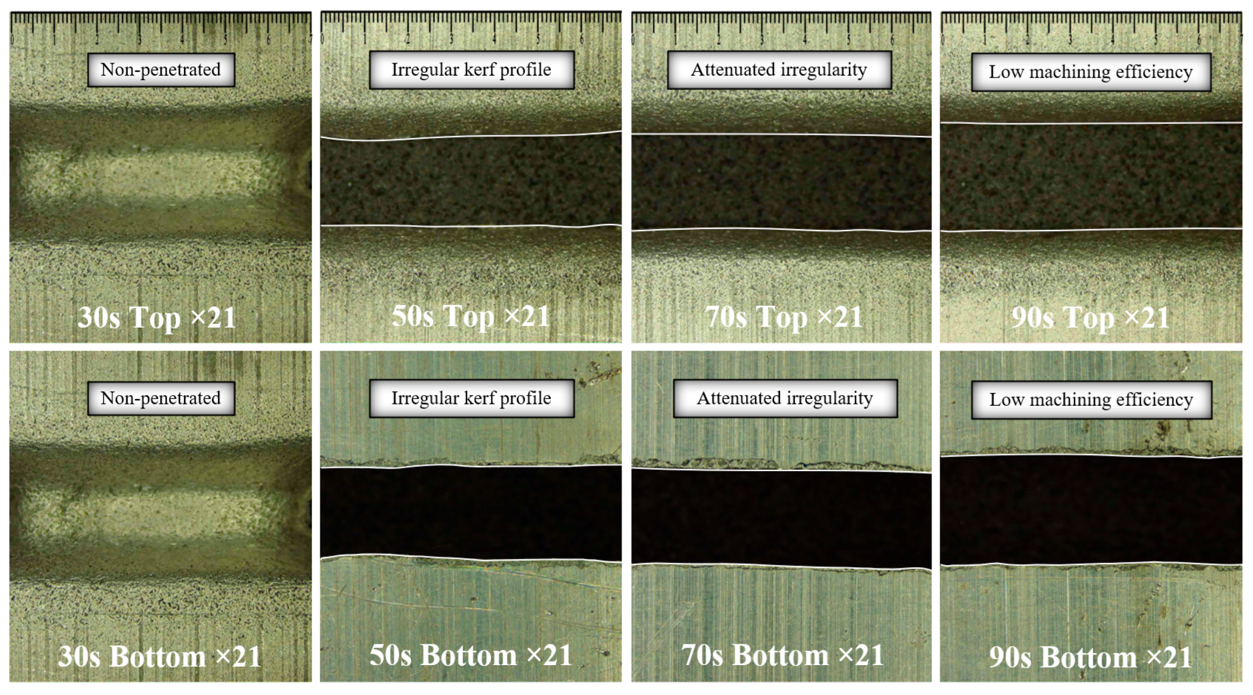
Bottom kerf width exhibited a two-stage trend: a sharp increase from about 1.8 mm at 30 s to 2.7 mm at 50 s, followed by a plateau between 50 s and 70 s, then a gradual rise to 3.1 mm at 90 s. The clear separation of error bars between 30 s and 50 s confirmed the initial increase was statistically significant, reflecting the transition from incomplete to full penetration (Figure 18). Overlapping error bars at 50 s and 70 s indicated no significant change in this plateau stage, while non-overlapping bars between 70 s and 90 s verified the final increase was significant. One-way ANOVA confirmed cutting time had a highly significant effect on bottom kerf width (p < 0.001). Under a constant peripheral speed, an increase in cutting time raises the cumulative abrasive impingement per unit area, thereby enhancing cutting efficiency.
Figure 18.
Kerf morphology at different cutting times.
Kerf taper decreased sharply from about 0.7 at 30 s to 0.45 at 50 s, then stabilized at a low level (0.45–0.55) for the remaining duration. Non-overlapping error bars between 30 s and 50 s confirmed the initial reduction in taper was statistically significant, corresponding to the transition to full penetration. Partial overlap of error bars between 50 s, 70 s, and 90 s indicated no significant further change in taper after full penetration. One-way ANOVA confirmed that the cutting time exerted a highly significant effect on taper (p < 0.001), driven by the attenuation of initial kerf bottom irregularities with cumulative abrasive action.
Overall, cutting time exerted a significant influence on three kerf geometry parameters, with the pronounced changes occurring during the transition from incomplete to full penetration (30–50 s). Extending cutting time beyond full penetration primarily improves kerf uniformity rather than drastically altering dimensions, aligning with the cumulative abrasive erosion mechanism.
4.5. Effect of Abrasive Mesh on Cutting Performance
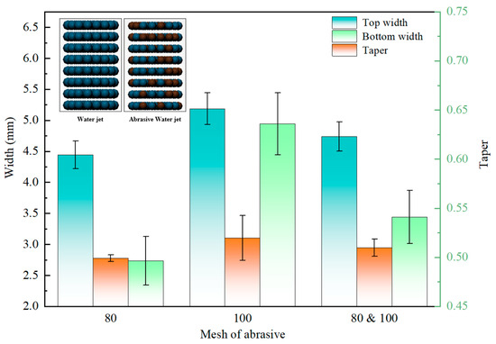
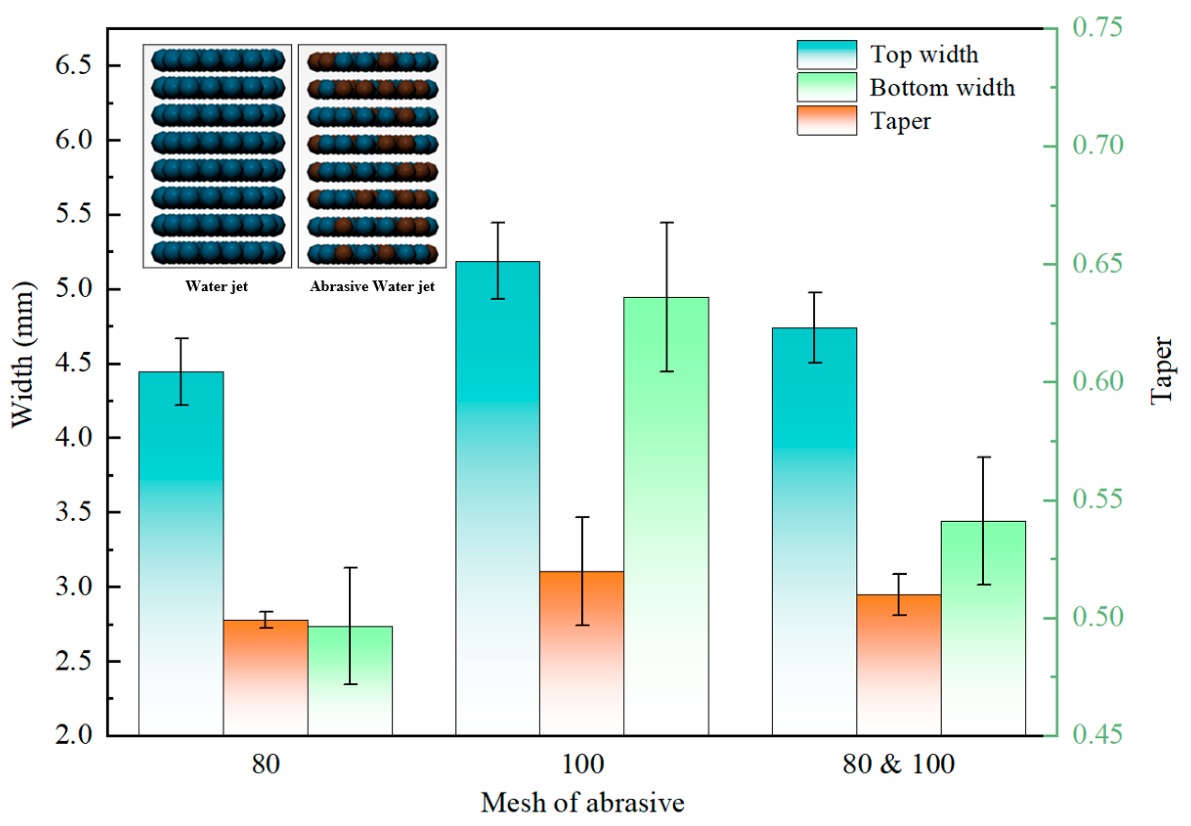
Figure 19 shows the effect of abrasive mesh on kerf parameters. All data are presented with error bars denoting the standard deviation of three independent replicate tests, providing a measure of experimental repeatability.
Figure 19.
Effect of abrasive mesh size on kerf parameters at a peripheral speed of 5.65 mm/s, a cutting time of 70 s, a pump pressure of 50 MPa, a standoff distance of 8.5 mm, and an abrasive mass fraction of 6.19% (±1.31%).
Regarding top kerf width, values increased from about 4.4 mm at 80 mesh to about 5.2 mm at 100 mesh, with the mixed mesh condition falling at about 4.7 mm. The non-overlapping error bars between 80 mesh and 100 mesh indicated this difference was statistically significant. While partial overlap was observed between the 80 mesh and the mixed group, one-way ANOVA confirmed that abrasive mesh size exerted a highly significant effect on top kerf width (p < 0.001). This trend aligns with the mechanism that finer abrasives (higher mesh number) have greater particle counts, leading to more dispersed erosion at the jet entrance.
For bottom kerf width, the lowest value was observed at 80 mesh (about 2.75 mm), while the highest value occurred at 100 mesh (about 4.95 mm), with the mixed mesh condition at about 3.45 mm. The clear separation of error bars between 80 mesh and 100 mesh confirmed this trend was statistically significant, reflecting the improved penetration ability of finer abrasives. Partial overlap between the mixed group and 80 mesh indicated no significant difference in this comparison, though ANOVA results verified the overall effect of abrasive mesh size on bottom kerf width was highly significant (p < 0.001).
Kerf taper values were relatively consistent across all three conditions, ranging from about 0.50 to about 0.52. The overlapping error bars across all mesh groups indicated no statistically significant differences in taper, which was confirmed by one-way ANOVA (p = 0.11), not significant at (α = 0.05). This suggests that while abrasive mesh size affects absolute kerf width, it has a limited impact on the relative uniformity of the kerf geometry under the tested conditions.
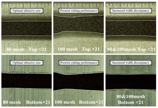
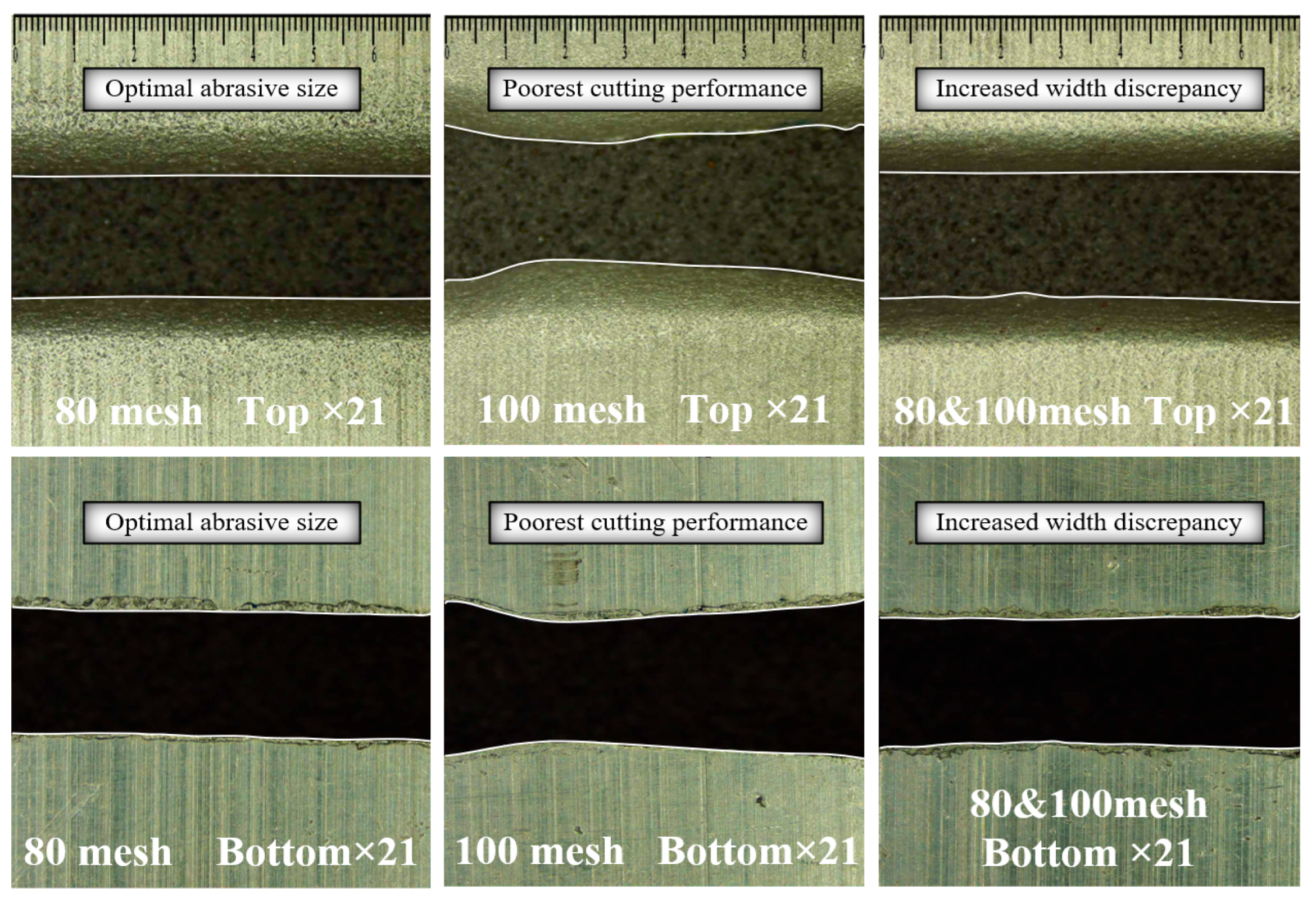
Overall, our experimental results identify 80-mesh abrasive particles as the optimal abrasive size for rotary AWJ cutting, and this observation is consistent with previously reported results in the literature [35]. Moreover, the quantitative analysis reveals that 80-mesh abrasive particles exhibit the smallest kerf width deviations. The maximum deviations in the top and bottom kerf widths are 0.10 mm and 0.13 mm. In contrast, the 80-/100-mesh abrasive blend shows larger deviations (0.29 mm for the top kerf width and 0.36 mm for the bottom kerf width), whereas the 100-mesh abrasive particles display the largest deviations (0.31 mm for the top kerf width and 0.95 mm for the bottom kerf width). Additionally, Figure 20 shows the evolution of kerf morphology across different mesh sizes, visually confirming the observed trends in width deviations. Notably, these deviations show that the bottom kerf width is more sensitive to changes in abrasive mesh size than the top kerf width. Specifically, 100-mesh abrasive particles exhibit inferior cutting performance, characterized by progressive kerf narrowing from the lateral regions toward the medial regions. Finally, the plastic deformation of the material (Al6061) leads to the formation of adherent burrs on the kerf floor, further supporting the selection of 80-mesh abrasive particles as the optimal compromise between cutting performance and kerf quality.
Figure 20.
Kerf morphology under different abrasive mesh sizes.
5. Conclusions
This study developed a self-designed test apparatus to investigate rotary AWJ cutting performance. A coupled SPH-FEM numerical model was established to elucidate the cutting mechanisms and parametric characteristics. Complemented by experimental validation, the effects of operational parameters on cutting behavior were investigated, leading to the formulation of optimized parameter-matching strategies. The core findings are listed below:
- (1)
- An integrated downhole rotary AWJ cutting device was designed with an abrasive mixing-conveyance system, electric ball-screw anchoring structure, and hydraulic adjustment unit. This design can reduce conveying wear and optimize parameter regulation, adapting to actual downhole working conditions.
- (2)
- Based on single-factor experiments, reasonable ranges of five key parameters were summarized, including peripheral speed of 5.65–7.54 mm/s, pump pressure of 50 MPa, standoff distance of 8.5 mm, cutting time above 50 s, and 80-mesh abrasives. This parameter combination is capable of balancing cutting quality and efficiency, and mitigating excessive energy loss, abrasive breakage, and incomplete cutting.
- (3)
- The established SPH-FEM model preliminarily revealed the microscopic cutting features and parameter influence laws from a numerical perspective, providing auxiliary interpretation for the cutting mechanism of rotary AWJ.
This work mainly focuses on macroscopic cutting performance. Further studies are required to explore microscale material removal and long-term structural damage. Extended experiments and optimized numerical models will be conducted in subsequent research to improve the practical applicability of rotary AWJ cutting for pipeline engineering.
Author Contributions
C.C.: Software, Data Curation, Writing-original draft, Writing—review and editing. H.J.: Writing-original draft, Investigation, Methodology. G.Y.: Funding acquisition, Formal analysis. L.Z.: Investigation, Validation. X.S.: Validation. S.Y.: Methodology. F.Z.: Writing—review & editing. Y.Z.: Formal analysis. All authors have read and agreed to the published version of the manuscript.
Funding
This work was supported by the National Natural Science Foundation Project (No. 42472383). Sichuan Province Overseas Returned Talents Selection and Funding Excellent Talents Project (No. 2023029). PetroChina Jianghan Machinery Research Institute Co., Ltd. Jingzhou. Chengdu ASBR Technology Co., Ltd. Chengdu.
Data Availability Statement
The datasets used or analysed during the current study are available from the corresponding author on reasonable request.
Conflicts of Interest
Gao Yang and Fuqiang Zhang are employed by the company PetroChina Jianghan Machinery Research Institute Co., Ltd. The authors declare that they have no known competing financial interests or personal relationships that could have appeared to influence the work reported in this paper.
Nomenclature
| mw | Mass of water per unit time, g/s | ma | Mass of abrasives per unit time, g/s |
| η | Mass fraction of abrasives | P | Pressure, MPa |
| T | Jetting time, s | h1 | Water level difference, mm |
| Vw | Water speed, m/s | Vaw | AWJ velocity, m/s |
| γ0 | Grueisen coefficient | S1,S2,S3 | Fitting coefficients |
| μ | Poisson’s ratio | C | Speed of sound |
| C0~C6 | Equation of state constants | E | Young’s modulus |
| Pthr | Pressure valve value, MPa | h2 | Cutting depth, mm |
| x-x′ | Distance between two particles, mm | vijβ | Relative velocity of the two particles in the β-direction |
| ΔVI | Metric of the domain around node i | xiβ | Coordinate of particle i in the β-direction |
| h | Smoothing length that defines the particle support domain, mm | ||
Appendix A
For rotary AWJ cutting of oil and gas well tubing, the large deformation and high strain rate of the waterjet lead to mesh distortion in the traditional Lagrangian FEM, which is prone to solution termination [36]. SPH—a meshless Lagrangian method—discretizes continuous fields into discrete particles via kernel function interpolation and simulates the mechanical behavior of the entire field by tracking particle trajectories [37,38]. This method eliminates issues of mesh distortion and element failure, offering significant advantages for large-deformation problems. To balance computational accuracy and efficiency, this study uses the SPH-FEM coupled method to simulate rotary AWJ cutting of tubing, integrating the large-deformation handling capability of SPH with the computational efficiency of FEM [39]. In this coupled framework, the tubing is modeled using FEM elements, whereas the AWJ is represented by SPH particles. SPH is particularly suitable for this simulation because of the large deformation and splashing phenomena occurring during the rotary AWJ cutting process [40]. Based on interpolation theory, SPH allows any function to be expressed on a set of disordered particles, where particle positions are defined by smooth kernel approximations. For any particle in the domain Ω, the function value can be expressed as:
where f(x) is a three-dimensional coordinate function of x, (x − x′) is the distance between two particles, and h is the smoothing length that defines the particle support domain [40,41].
The conservation equations controlling the evolution of the mechanical variables can be expressed as the mass conservation equation (Equation (A2)) and conservation of momentum equation (Equation (A3)).
where vijβ is the relative velocity of the two particles in the β-direction and xiβ is the coordinate of particle i in the β-direction.
The Lagrangian form of the momentum conservation equation is written as:
where vijβ is the relative velocity of the two particles in the β-direction and xiβ is the coordinate of particle i in the β-direction.
Since the coupled SPH/FEM problem is a three-dimensional problem, a discrete simulation of Equation (A1) is required:
where ΔVI is the metric of the domain around node i.
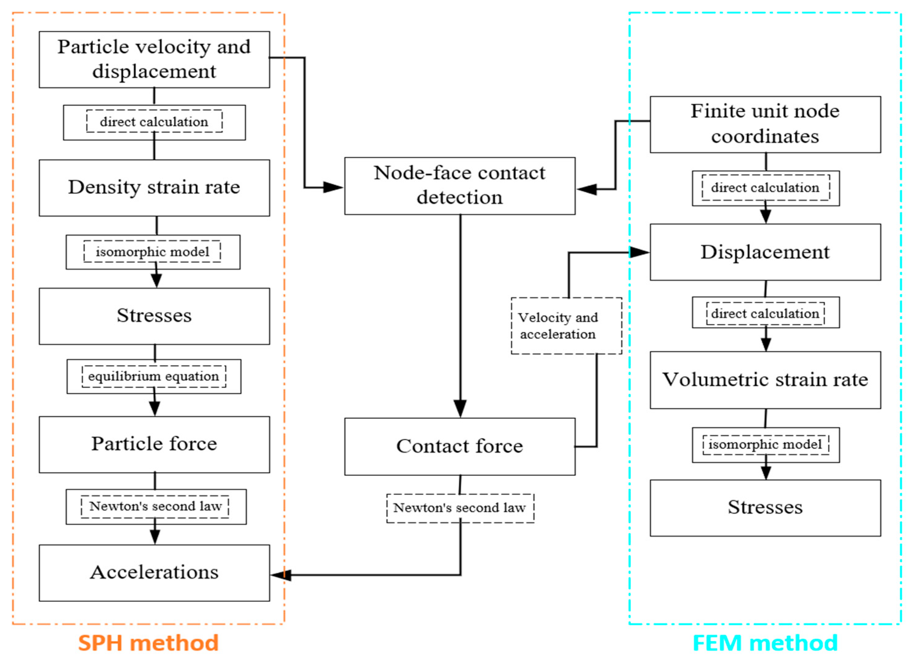
SPH discretization constitutes a specialized particle-based discretization governed by the particle count and mass. Penalty-based coupling transfers particle forces to FEM domains via node-to-surface contact methodology, where SPH particles are designated slave nodes and FEM surfaces master entities [42].
SPH particles are used for both abrasive and water, and the modeling process of AWJ is shown in Figure A1 [39].
Figure A1.
SPH-FEM coupling flow chart.
References
- Tang, J.; Yan, X.; Liu, W.; Zhang, H.; Cui, J.; Zhang, Z. Structural optimization of self-suction abrasive jet nozzle for tubing cutting in oil and gas wells: CFD-DEM and experimental study. Powder Technol. 2025, 465, 121313. [Google Scholar] [CrossRef] [Scilit]
- Zai, P.; Yuan, R.; Wang, H.; Fan, J.; Deng, J. Numerical simulation and experimental research on sandstone breaking by abrasive water jet based on microscopic perspective. Powder Technol. 2025, 454, 120709. [Google Scholar] [CrossRef] [Scilit]
- Zhao, J.; Liao, H.; Xu, Y.; Shi, F.; Sun, B.; Chang, F.; Han, X. Experimental and theoretical evaluation of tubing cutting with rotating particle jet in oil and gas borehole operation. Energy 2023, 282, 128468. [Google Scholar] [CrossRef] [Scilit]
- Cano-Salinas, L.; Sourd, X.; Moussaoui, K.; Le Roux, S.; Salem, M.; Hor, A.; Zitoune, R. Effect of process parameters of Plain Water Jet on the cleaning quality, surface and material integrity of Inconel 718 milled by Abrasive Water Jet. Tribol. Int. 2023, 178, 108094. [Google Scholar] [CrossRef] [Scilit]
- Natarajan, Y.; Murugesan, P.K.; Mohan, M.; Khan, S.A.L. Abrasive Water Jet Machining process: A state of art of review. J. Manuf. Processes 2020, 49, 271–322. [Google Scholar] [CrossRef] [Scilit]
- Chukwuemeka, A.O.; Oluyemi, G.; Mohammed, A.I.; Njuguna, J. Plug and abandonment of oil and gas wells—A comprehensive review of regulations, practices, and related impact of materials selection. Geoenergy Sci. Eng. 2023, 226, 211718. [Google Scholar] [CrossRef] [Scilit]
- Pahuja, R.; Ramulu, M. Abrasive water jet machining of Titanium (Ti6Al4V)–CFRP stacks—A semi-analytical modeling approach in the prediction of kerf geometry. J. Manuf. Processes 2019, 39, 327–337. [Google Scholar] [CrossRef] [Scilit]
- Townsend-Small, A.; Ferrara, T.W.; Lyon, D.R.; Fries, A.E.; Lamb, B.K. Emissions of coalbed and natural gas methane from abandoned oil and gas wells in the United States. Geophys. Res. Lett. 2016, 43, 2283–2290. [Google Scholar] [CrossRef] [Scilit]
- Sourd, X.; Zitoune, R.; Hejjaji, A.; Salem, M.; Hor, A.; Lamouche, D. Plain water jet cleaning of titanium alloy after abrasive water jet milling: Surface contamination and quality analysis in the context of maintenance. Wear 2021, 477, 203833. [Google Scholar] [CrossRef] [Scilit]
- Hlaváč, L.M.; Kocich, R.; Kunčická, L.; Hlaváčová, I.M.; Gřunděl, J. Effect of thermomechanical post-processing of additively manufactured AISI 316L steel on abrasive water jet wear. Wear 2025, 570, 205952. [Google Scholar] [CrossRef] [Scilit]
- Kong, L.; Wang, Y.; Lei, X.; Feng, C.; Wang, Z. Integral Modeling of Abrasive Waterjet Micro-Machining Process. Wear 2021, 482–483, 203987. [Google Scholar] [CrossRef] [Scilit]
- Hu, Y.; Wang, F.; Jiang, F.; Hu, L.; Huang, G. Simulation Analysis of Damage and Energy Consumption of Rocks During Abrasive Water Jet Impacts Based on SPH-FEM Method. Powder Technol. 2025, 449, 120418. [Google Scholar] [CrossRef] [Scilit]
- Fujisawa, K. Experimental Investigation of Impact Force Variations During High-Speed Liquid Impingement Erosion. Wear 2024, 538–539, 205180. [Google Scholar] [CrossRef] [Scilit]
- Zhang, Y.; Wu, X.; Hu, X.; Zhang, B.; Lu, J.; Zhang, P.; Li, G.; Tian, S.; Li, X. Visualization and Investigation of the Erosion Process for Natural Gas Hydrate Using Water Jet Through Experiments and Simulation. Energy Rep. 2022, 8, 202–216. [Google Scholar] [CrossRef] [Scilit]
- Yabuki, A.; Matsumura, M. Theoretical Equation of the Critical Impact Velocity in Solid Particles Impact Erosion. Wear 1999, 233–235, 476–483. [Google Scholar] [CrossRef] [Scilit]
- Lu, Y.; Huang, F.; Liu, X.; Ao, X. On the Failure Pattern of Sandstone Impacted by High-Velocity Water Jet. Int. J. Impact Eng. 2015, 76, 67–74. [Google Scholar] [CrossRef] [Scilit]
- Parsi, M.; Najmi, K.; Najafifard, F.; Hassani, S.; McLaury, B.S.; Shirazi, S.A. A Comprehensive Review of Solid Particle Erosion Modeling for Oil and Gas Wells and Tubings Applications. J. Nat. Gas Sci. Eng. 2014, 21, 850–873. [Google Scholar] [CrossRef] [Scilit]
- Chen, M.; Zhang, S.; Lu, G.; Wu, Y. Method of Ensemble Modeling for Abrasive Water Jet Machinability of Metal Materials. J. Manuf. Processes 2024, 110, 291–302. [Google Scholar] [CrossRef] [Scilit]
- Wan, L.; Lu, W.; Qian, Y.; Wu, S.; Kang, Y.; Li, D. Experimental Study on the Cutting Performance of Abrasive Waterjet Using Steel Slag as the Particles. J. Manuf. Processes 2023, 108, 877–888. [Google Scholar] [CrossRef] [Scilit]
- Chen, J.; Wang, C.; Liu, G.; Liu, Z.; Luo, Q. Tubing Cutting Technology through Abrasive Water Jet and Its Applications in Offshore Abandoned Wells. Pet. Drill. Technol. 2013, 41, 46–51. [Google Scholar]
- Karthik, K.; Sundarsingh, D.S.; Harivignesh, M.; Karthick, R.G.; Praveen, M. Optimization of Machining Parameters in Abrasive Water Jet Cutting of Stainless Steel 304. Mater. Today Proc. 2021, 46, 1384–1389. [Google Scholar] [CrossRef] [Scilit]
- Perec, A.; Kawecka, E.; Zajac, W. AWJ Cutting Process Quality Modeling and Optimization Based on Footprint Angle. Materials 2025, 18, 5548. [Google Scholar] [CrossRef] [Scilit]
- Zhang, S.; Zhang, Z.; Lu, L.; Wang, Z.; Yao, P. Overview on Material Removal Mechanisms and Surface Textures Modelling in Abrasive Jet Machining Processes. Int. J. Adv. Manuf. Technol. 2025, 137, 3165–3213. [Google Scholar] [CrossRef] [Scilit]
- Říha, Z.; Zeleňák, M.; Nag, A.; Poloprudský, J.; Kruml, T.; Hloch, S. A Study of the Erosion Characteristics of an EN AE-6060 Aluminium Alloy Processed Using Middle and High Power Continuous and Modulated Water Jets. Wear 2024, 536–537, 205154. [Google Scholar] [CrossRef] [Scilit]
- Yuan, Y.; Chen, J.; Gao, H. Surface Profile Evolution Model for Titanium Alloy Machined Using Abrasive Waterjet. Int. J. Mech. Sci. 2023, 240, 107911. [Google Scholar] [CrossRef] [Scilit]
- Llanto, J.M.; Tolouei-Rad, M.; Vafadar, A.; Aamir, M. Recent Progress Trend on Abrasive Waterjet Cutting of Metallic Materials: A Review. Appl. Sci. 2021, 11, 3344. [Google Scholar] [CrossRef] [Scilit]
- Li, H.; Li, J.; Huang, Z.; Guo, C.; Wang, H.; Li, W. Numerical Investigation of Abrasive Water Jet Impact Force Characteristics by Using the Coupled SPH-FEM Method: Considering the Shape, the Interaction and the Fragmentation of Abrasive Particles. Powder Technol. 2025, 465, 121287. [Google Scholar] [CrossRef] [Scilit]
- Dong, X.W.; Liu, G.R.; Li, Z.; Zeng, W. A Smoothed Particle Hydrodynamics (SPH) Model for Simulating Surface Erosion by Impacts of Foreign Particles. Tribol. Int. 2016, 95, 267–278. [Google Scholar] [CrossRef] [Scilit]
- Jiang, H.; Zhao, H.; Gao, K.; Wang, O.; Wang, Y.; Meng, D. Numerical Investigation of Hard Rock Breakage by High-Pressure Water Jet Assisted Indenter Impact Using the Coupled SPH/FEM Method. Powder Technol. 2020, 376, 176–186. [Google Scholar] [CrossRef] [Scilit]
- El Mesalamy, A.S.; Youssef, A. Enhancement of Cutting Quality of Abrasive Waterjet by Using Multipass Cutting Strategy. J. Manuf. Processes 2020, 60, 530–543. [Google Scholar] [CrossRef] [Scilit]
- Huang, F.; Mi, J.; Li, D.; Wang, R.; Zhao, Z. Comparative Investigation of the Damage of Coal Subjected to Pure Water Jets, Ice Abrasive Water Jets and Conventional Abrasive Water Jets. Powder Technol. 2021, 394, 909–925. [Google Scholar] [CrossRef] [Scilit]
- Fowler, G.; Pashby, I.R.; Shipway, P.H. The Effect of Particle Hardness and Shape When Abrasive Water Jet Milling Titanium Alloy Ti6Al4V. Wear 2009, 266, 613–620. [Google Scholar] [CrossRef] [Scilit]
- Orbanic, H.; Junkar, M. Analysis of Striation Formation Mechanism in Abrasive Water Jet Cutting. Wear 2008, 265, 821–830. [Google Scholar] [CrossRef] [Scilit]
- Hashish, M.; Loscutoff, W.V.; Reich, P. Cutting with Abrasive Waterjets. In Proceedings of the Second U.S. Water Jet Conference, Rolla, MO, USA, 24–26 May 1983; WaterJet Technology Association: St. Louis, MO, USA, 1983; pp. 65–66. Available online: https://api.semanticscholar.org/CorpusID:108231822 (accessed on 2 March 2026).
- Han, T.W.; Gao, P.Y.; Chen, S.; Liu, C.; Zhang, H. Experimental Study on Parameter Optimization of Pre-Mixed Abrasive Jet Cutting Casing. J. Shandong Inst. Petrol. Chem. Technol. 2024, 38, 85–89. Available online: http://m.qikan.cqvip.com/article/ArticleDetail?id=7200238869 (accessed on 2 March 2026).
- Cai, C.; Zhang, P.; Xu, D.; Yang, X.; Zhou, Y. Composite Rock-Breaking of High-Pressure CO2 Jet & Polycrystalline-Diamond-Compact (PDC) Cutter Using a Coupled SPH/FEM Model. Int. J. Min. Sci. Technol. 2022, 32, 1115–1124. [Google Scholar] [CrossRef] [Scilit]
- Shet, C.; Deng, X.; Bayoumi, A.E. Finite Element Simulation of High-Pressure Water-Jet Assisted Metal Cutting. Int. J. Mech. Sci. 2003, 45, 1201–1228. [Google Scholar] [CrossRef] [Scilit]
- Cai, C.; Xie, Q.; Zhong, T.; Zhao, Y.; Fan, K.; Zhou, Y.; Zhang, L. The Thermal-Fluid-Mechanical (TFM) Coupling Method Based on Discrete Element Method (DEM) and the Application of CO2 Fracturing Analysis. Geoenergy Sci. Eng. 2024, 232, 212443. [Google Scholar] [CrossRef] [Scilit]
- Zou, X.; Fu, L.; Wu, L. Multiphase Flow and Nozzle Wear with CFD-DEM in High-Pressure Abrasive Water Jet. Powder Technol. 2024, 444, 120019. [Google Scholar] [CrossRef] [Scilit]
- Cai, C.; Cao, W.; Yang, X.; Zhang, P.; Zeng, L.; Zhou, S. Study on Composite Rock-Breaking Mechanism of Ultrahigh-Pressure Water Jet–PDC Cutter. SPE J. 2024, 29, 3892–3904. [Google Scholar] [CrossRef] [Scilit]
- Ma, Q.; Lin, J.; Yang, K.; Xie, H.; Guo, C. Experimental Study on Abrasive Recycling in Cutting with Abrasive Suspension Water Jet. Int. J. Adv. Manuf. Technol. 2021, 114, 969–979. [Google Scholar] [CrossRef] [Scilit]
- Perec, A. Research into the Disintegration of Abrasive Materials in the Abrasive Water Jet Machining Process. Materials 2021, 14, 3940. [Google Scholar] [CrossRef] [Scilit]


Disclaimer/Publisher’s Note: The statements, opinions and data contained in all publications are solely those of the individual author(s) and contributor(s) and not of MDPI and/or the editor(s). MDPI and/or the editor(s) disclaim responsibility for any injury to people or property resulting from any ideas, methods, instructions or products referred to in the content. |
© 2026 by the authors. Licensee MDPI, Basel, Switzerland. This article is an open access article distributed under the terms and conditions of the Creative Commons Attribution (CC BY) license.