Article

Geometry-Driven Distortion Mechanisms in Thin-Walled Rotating Shells Fabricated by Laser Beam Powder Bed Fusion

1
Hunan Gaochuang Xiangyu Equipment Technology Co., Ltd., Changsha 410200, China
2
State Key Laboratory of Solidification Processing, Northwestern Polytechnical University, Xi’an 710072, China
*
Author to whom correspondence should be addressed.
J. Manuf. Mater. Process. 2026, 10(2), 72; https://doi.org/10.3390/jmmp10020072
Submission received: 7 January 2026 / Revised: 9 February 2026 / Accepted: 15 February 2026 / Published: 19 February 2026
(This article belongs to the Special Issue Advances in Metal Forming and Additive Manufacturing)

Abstract

Laser beam powder bed fusion (PBF-LB) enables the fabrication of complex rotational metallic components for aerospace applications, such as engine exhaust nozzles and combustion liners, but the localized thermal cycles inherent to the process often lead to residual stress accumulation and geometry-dependent distortion, particularly in low-stiffness and open structures. This study investigates the thermo-mechanical response of three representative 316L stainless steel rotational geometries—dumbbell-shaped, cylindrical, and drum-shaped—in both closed and open configurations using a transient, fully coupled thermo-mechanical finite element model validated by high-resolution three-dimensional deformation measurements. The results reveal pronounced geometry- and size-dependent distortion mechanisms: for closed structures, the drum-shaped geometry exhibits the largest radial contraction and stress concentration due to its larger characteristic size and lower stiffness, with a maximum deformation of approximately 0.14 mm, whereas the dumbbell-shaped and cylindrical geometries show smaller and more uniform deformations of about 0.09 mm and 0.12 mm; open configurations experience substantially amplified distortion, with both the magnitude and vertical location of bulging governed by geometric stiffness and substrate constraint, and the open drum-shaped structure reaching a maximum displacement of approximately 1.6 mm. These findings clarify how geometric size and stiffness control stress relaxation and shape stability in PBF-LB-fabricated rotational components and provide transferable guidance for geometry-informed design and distortion mitigation in high-precision additive manufacturing.

1. Introduction

Laser Beam Powder Bed Fusion (PBF-LB) is a representative metal additive manufacturing (AM) technology [1] that enables the near-net-shape fabrication of complex three-dimensional components through layer-wise selective melting of metal powders. Owing to its high geometric freedom, dimensional accuracy, and material utilization efficiency, PBF-LB has been increasingly applied in the production of high-performance components for aerospace [2], energy [3], and biomedical applications [4], particularly where lightweight design and complex internal features are required. Compared with conventional subtractive or forming processes, PBF-LB offers superior flexibility in design iteration and customization, thereby promoting advanced manufacturing toward intelligent, lightweight, and integrated production paradigms [5,6].
Despite these advantages, the PBF-LB process is inherently characterized by highly localized energy input and rapid heating–cooling cycles. Temperature gradients on the order of 107 °C/m and cooling rates as high as 107 °C/s are commonly generated during fabrication, leading to severe thermal mismatch and non-uniform thermal expansion and contraction. These extreme thermal conditions induce complex residual stress fields [7,8], which may result in part distortion, dimensional instability, or even cracking when the accumulated stress exceeds structural or material limits [9,10,11]. Such issues are particularly critical for thin-walled components, where low structural stiffness and limited load-bearing capacity amplify sensitivity to thermal stress. Consequently, thin-walled structures fabricated by PBF-LB are prone to warping, buckling, or collapse, seriously compromising geometric accuracy, structural integrity, and service reliability [12,13,14].
In AM research, the finite element (FE) method is a highly important tool, particularly for coupled thermo-mechanical and electro-thermal analyses [15]. It enables the prediction and understanding of residual stresses, distortions, and temperature evolution in complex components. Consequently, a large body of experimental and FE simulation work has been conducted to control deformation and residual stresses in thin-walled structures produced by PBF-LB, through both process optimization and structural design strategies. Calignano et al. [16] investigated the influence of process parameters on the forming quality of thin-walled structures and proposed a regression-based model to evaluate the manufacturability of thin walls under given processing conditions. Cai et al. [17] further demonstrated that high-quality thin-walled components can be successfully fabricated through process parameter optimization, achieving improvements of 6.1% and 15.9% in ultimate tensile strength and yield strength, respectively. Zhao et al. [18] further identified an optimized scanning strategy and process parameter window that effectively reduced heat accumulation and residual stress, leading to improved dimensional accuracy and geometric stability of PBF-LB-fabricated 316L thin-walled ring structures. Buchbinder et al. [19], Lu et al. [20], Cao et al. [21] demonstrated that build-plate or powder-bed preheating effectively reduces thermal gradients during PBF-LB, thereby suppressing residual stress accumulation and mitigating distortion in fabricated components. Lu et al. [22] introduced geometric modifications such as stiffening ribs effectively increases local structural stiffness and thereby alleviates warping tendencies during PBF-LB fabrication. In addition, Ding et al. [23] investigated geometric deviations in thin-walled shell lattice structures fabricated via high-precision PBF-LB and proposed compensation strategies based on predictive modeling, demonstrating that pre-adjusting the design according to anticipated distortions can significantly improve dimensional accuracy in complex lattice components. Chen et al. [24] investigated the deformation behavior of thin-walled Ti–6Al–4V components during laser powder bed fusion and proposed a control strategy combining process parameter adjustment and support design to effectively mitigate distortion. Hussain et al. [25] demonstrated the fabrication of high-aspect-ratio, ultra-thin-walled Ti-6Al-4V structures using powder bed fusion assisted by in situ focused infrared heating, showing that localized thermal control can significantly reduce distortion and improve structural robustness in ultra-thin-walled additive manufacturing components. However, the effectiveness of these approaches strongly depends on component geometry and size, and they do not fundamentally clarify how geometric evolution governs stress accumulation and deformation behavior in thin-walled structures.
The size effect in AM has therefore attracted increasing attention. Prior studies have demonstrated that component size and characteristic dimensions significantly influence residual stress, deformation, and even mechanical properties. Wu et al. [26] systematically studied the fabrication limits of thin-walled structures in the PBF-LB process and analyzed the effects of size and wall thickness on surface morphology, microstructure, and mechanical performance. Lu et al. [22] designed thin-walled structures with different geometric features and systematically examined their sensitivity to size. Ahmed et al. [27] employed thermo-mechanical numerical simulations to analyze the evolution mechanisms of residual stresses in thin-walled structures of Ti64, SS316L, and IN718 alloys under different tapers. Jia et al. [28] reported that, for aircraft blades, the deformation of parts after removal from the substrate increases with component size, following a cubic regression trend. Moreover, Roach et al. [29] found that for characteristic dimensions smaller than 7 mm, the effective yield strength, ultimate tensile strength, and elastic modulus of 316L stainless steel all decrease significantly as the specimen size decreases. Leicht et al. [30] also observed that reducing part thickness does not affect the microstructure but leads to a decrease in tensile properties. Nevertheless, most existing studies focus on simple geometries or global size variations, with limited attention to thin-walled structures exhibiting continuously evolving geometry along the build direction.
Thin-walled rotational structures—including shells, casings, and pressure-bearing housings [31,32]—are widely used in aerospace and energy systems. For these structures, local variations in cross-sectional diameter and stiffness induce non-uniform thermal accumulation and stress redistribution, making deformation highly geometry-dependent. Moreover, many applications involve open thin-walled configurations, where reduced structural stiffness further amplifies deformation and introduces distinctive bulging behavior under residual stress [22]. Despite their engineering relevance, systematic understanding of how geometric evolution, size effects, and structural openness interact to govern stress and deformation during PBF-LB fabrication remains insufficient, limiting the rational design and distortion control of such components.
To address these gaps, the present study systematically investigates three representative thin-walled rotational geometries—dumbbell-shaped, cylindrical, and drum-shaped structures—fabricated from 316L stainless steel by PBF-LB. Both closed and open thin-walled configurations derived from these geometries are analyzed to capture the influence of reduced stiffness on deformation behavior. By combining high-precision three-dimensional deformation measurements with a thermo-mechanically coupled FE framework, the temperature evolution, residual stress development, and final deformation characteristics associated with different geometric configurations are quantitatively evaluated. Particular emphasis is placed on elucidating the effects of structural size, geometric evolution, and opening on the thermo-mechanical response during fabrication. From the perspective of structural size variation, the size effect on rotational components is highlighted, whereas geometric evolution is considered primarily to reflect the characteristic features of critical aerospace components. The results provide mechanistic insights and quantitative guidance for geometry optimization, distortion mitigation, and process planning in PBF-LB fabrication of thin-walled rotational components.

2. Experimental Methods

2.1. Powder Material and Specimen Preparation

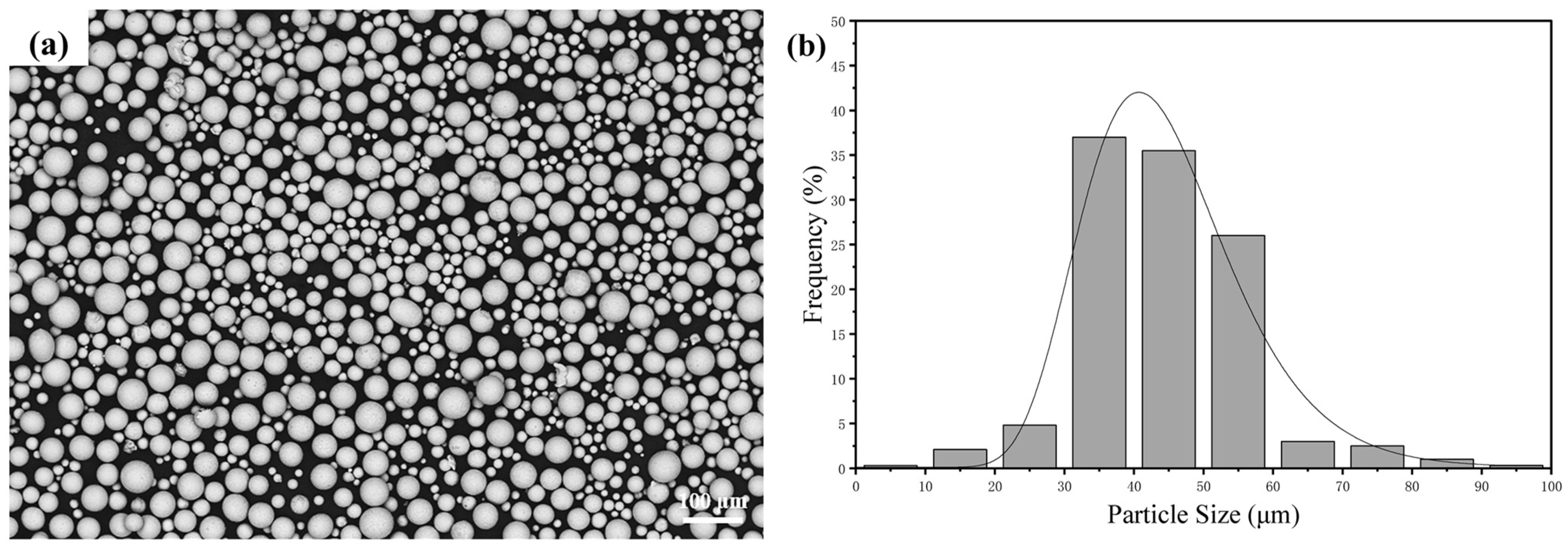
Rotating-electrode-atomized 316L stainless steel powder 316L stainless steel powder, supplied as a commercial powder by Xi’an Ouzhong Material Technology Co. Ltd. (Xi’an, China), was employed as the feedstock material for all PBF-LB experiments. The powder was produced via a rotating electrode atomization process, exhibiting a predominantly spherical morphology with a particle size distribution ranging from 15 to 53 μm, as shown in Figure 1, and its chemical composition is listed in Table 1. The smooth particle surfaces and narrow size range facilitate uniform powder spreading and stable melt pool formation, which are particularly critical for thin-walled geometries. Prior to fabrication, the powder is dried in a vacuum furnace at 130 °C for 2.5 h to eliminate adsorbed moisture and reduce the risk of spatter formation and gas-induced porosity during processing [33,34].
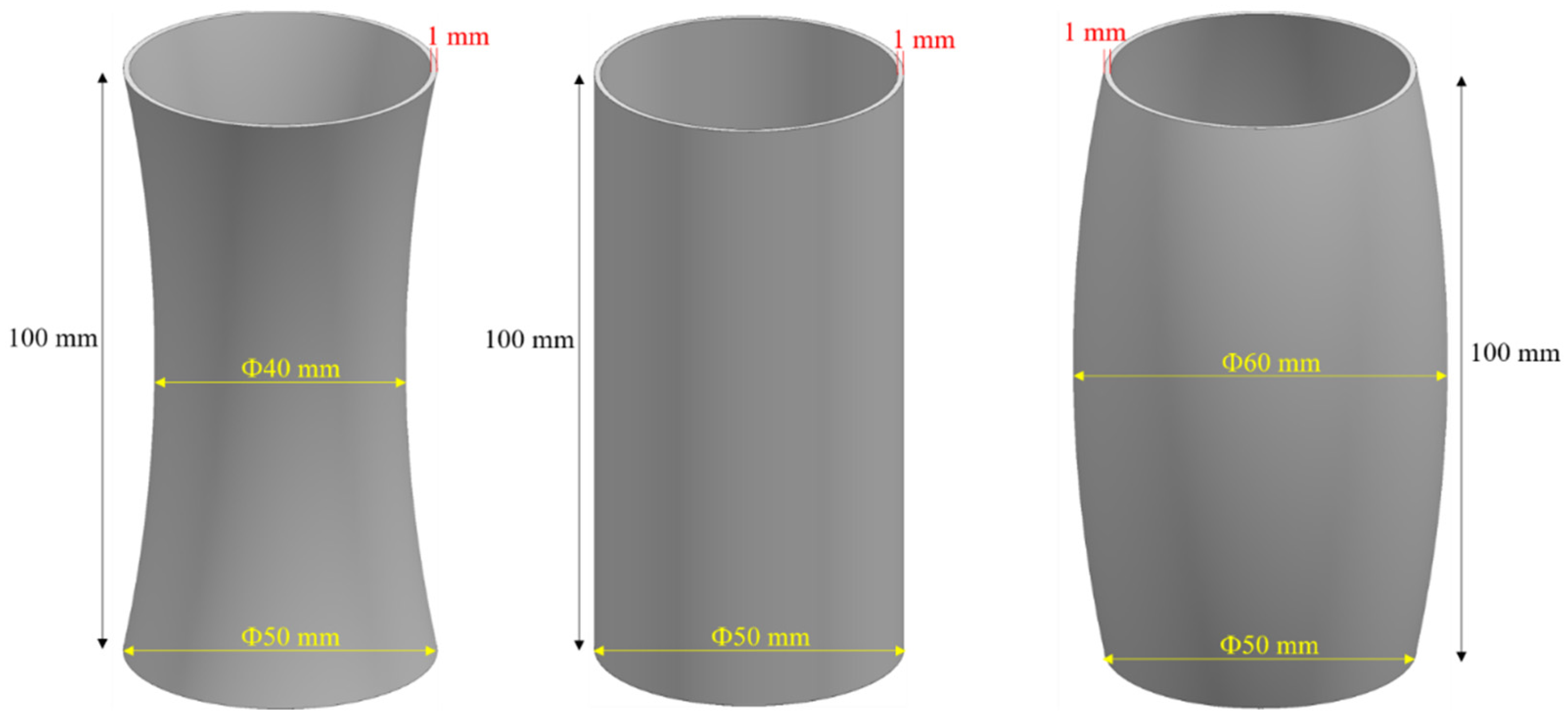
All specimens are fabricated on an annealed 316L stainless steel substrate with dimensions of 400 mm × 250 mm × 40 mm. The relatively large thermal mass and the thermal conductivity of the 316L substrate relative to the powder layer help stabilize the thermal boundary conditions during the initial build stages and ensure reproducible heat dissipation across the build area. Three representative thin-walled rotating shell geometries—a dumbbell-shaped shell with a reduced mid-section, a constant-diameter cylindrical shell, and a drum-shaped shell with a maximum diameter at mid-height—are designed to isolate geometry-driven thermo-mechanical effects, as illustrated in Figure 2. All geometries are assigned a uniform wall thickness of 1 mm, which represents a typical thin-walled condition in PBF-LB and minimizes thickness-induced variability, thereby enabling a direct comparison of curvature evolution, stiffness variation, and diameter-dependent heat accumulation effects.

2.2. PBF-LB Fabrication

The thin-walled rotating shells are fabricated using a commercial BLT-S400 PBF-LB system equipped with three fiber lasers operating at wavelengths between 1060 and 1080 nm. The system supports layer thicknesses ranging from 20 to 100 μm and maximum scanning speeds of up to 7 m/s. Based on a series of preliminary optimization trials, a stable processing parameter set is selected to ensure full densification, consistent melt pool behavior, and minimal process-induced defects. The detailed parameters are summarized in Table 2.
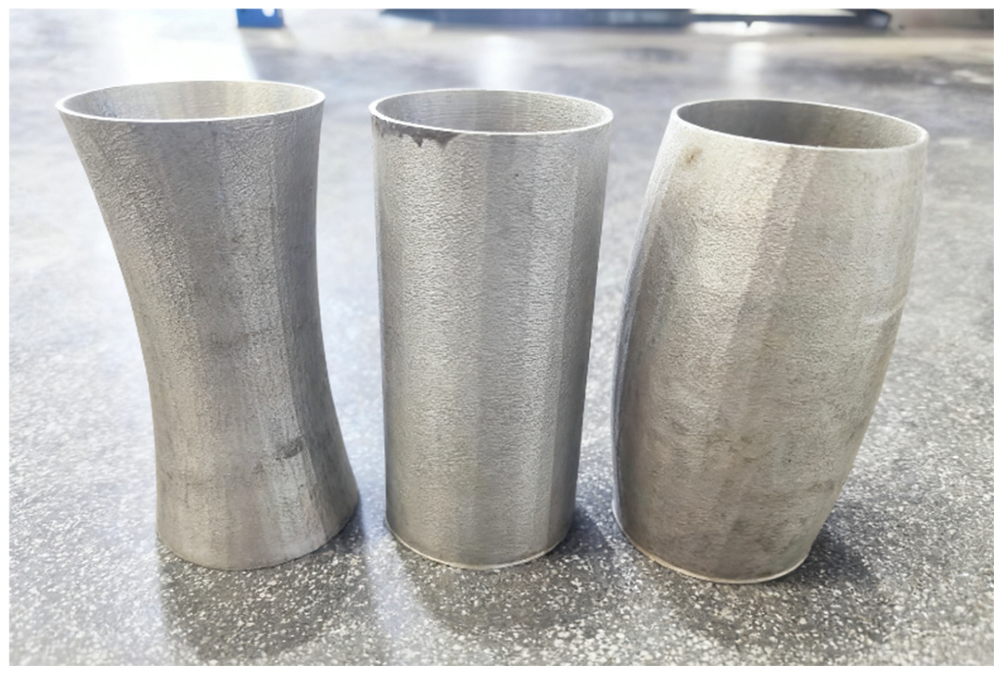
A stripe scanning strategy with a stripe width of 10 mm is employed, and the scanning direction is rotated by 67° between successive layers to mitigate directional thermal accumulation. No substrate preheating is applied in order to preserve strong thermal gradients and thereby accentuate geometry-induced thermo-mechanical effects. Identical process parameters and scanning strategies are used for all three geometries, ensuring that any observed differences in deformation behavior originate primarily from geometric configuration rather than process variability. Throughout fabrication, the build chamber is filled with high-purity argon, and the oxygen level is maintained below 100 ppm to prevent oxidation. After printing, the build chamber is allowed to cool naturally to room temperature prior to powder removal and part extraction. The as-built components are shown in Figure 3.

2.3. 3D Deformation Measurement

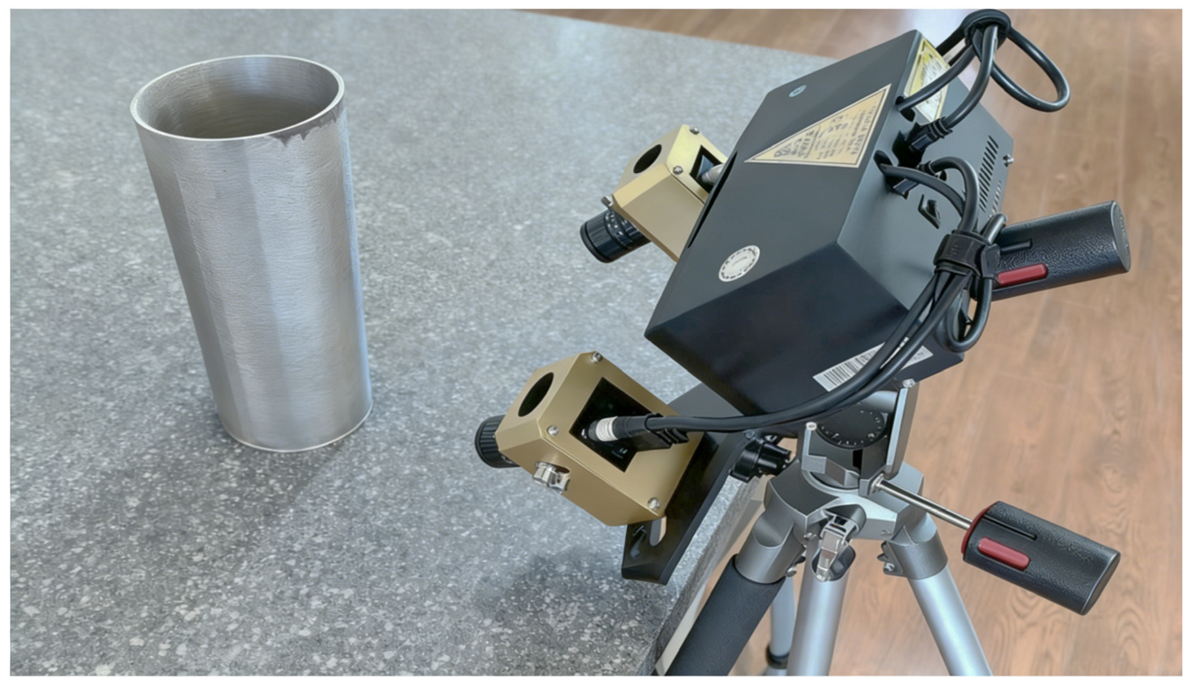
The geometric accuracy and deformation characteristics of the fabricated thin-walled shells are quantified using an industrial-grade fixed three-dimensional scanning system (Lingchuang G5-630), as shown in Figure 4. The system provides a spatial resolution of 0.01 mm, enabling reliable capture of subtle deformation features on thin and curved surfaces. A multi-angle scanning strategy is adopted to ensure complete surface coverage, particularly for regions with complex curvature or local geometric transitions, such as the reduced section of the dumbbell geometry.
The acquired point cloud data are aligned with the nominal CAD models using Geomagic Control X software (V2020.1). A best-fit registration procedure is applied to minimize systematic alignment errors, after which surface deviation maps are generated to visualize local deformation amplitudes. Radial contraction profiles are extracted along the build direction for quantitative comparison with numerical predictions. These high-fidelity deformation measurements serve as direct validation benchmarks for the thermo-mechanically coupled FE simulations.

3. Computational Simulation

3.1. FE Modeling of PBF-LB

In this work, the thermal and mechanical responses of the thin-walled rotating structures during the PBF-LB process are predicted using a coupled thermo-mechanical FE framework [20,35]. The adopted solution strategy follows the built-in thermo-mechanical coupling scheme of the FE software (Comet), in which the coupling is handled using a fractional step method with a staggered iterative solution. For each time increment, the transient heat transfer problem is solved first, after which the mechanical response is evaluated based on the resulting temperature field. This sequential coupling strategy ensures numerical stability while retaining sufficient accuracy in capturing the strongly coupled thermo-mechanical interactions characteristic of PBF-LB.
The latent heat contribution associated with phase transformation is neglected, as the characteristic time scale of melting and solidification is significantly smaller than the time step adopted in the transient thermal analysis. Material deposition is simulated using a birth–death element activation technique, whereby elements corresponding to newly deposited material are progressively activated following the prescribed laser scanning strategy [36]. The thermal influence of the surrounding loose powder bed is accounted for through equivalent thermal boundary conditions. Owing to its negligible stiffness, the loose powder does not contribute to the mechanical response of the build and is therefore excluded from the mechanical computational domain. A layer-by-layer activation strategy is employed, in which multiple physical layers are grouped into a single computational layer, substantially improving computational efficiency without compromising the accuracy required for deformation prediction [37].

3.2. Thermomechanical Governing Equations

During the PBF-LB process, the transient thermal field is governed by the energy balance equation, expressed as:
H ˙ = − ∇ · q + Q ˙
where H ˙ is the enthalpy rate. The volumetric heat source, Q ˙ , is computed as:
Q ˙ = P ˙ η V p o o l
where P ˙ is the nominal laser power, η is the actual power absorption parameter and V p o o l = w 2 ( h l + h r ) is the melt-pool volume being w the laser spot diameter, h l the layer thickness and h r is the melt-pool depth.
The heat flux, q , is expressed through Fourier’s law:
q = − k ∇ T
where k ( T ) and ∇ T are the thermal conductivity coefficient and the thermal gradients, respectively.
The heat loss due to convection is defined by Newton’s law:
q c o n v = h c o n v ( T − T r o o m )
where h c o n v is the Heat Transfer Coefficient (HTC) by convection, T is the temperature of the part surface and T r o o m is the room temperature.
The radiation heat flux is obtained by Stefan-Boltzmann’s law:
q r a d = ε r a d σ r a d T 4 − T r o o m 4
where ε r a d is the emissivity coefficient and σ r a d is the Stefan Boltzmann constant.
The mechanical problem is governed by the balance of momentum and the continuity equations:
∇ · s + ∇ p + b = 0
∇ · u − e T − p K = 0
where b are the body forces, u is the displacement field, e T is the thermal deformation, K ( T ) is the bulk (or compressibility) modulus while s and p are the spherical and deviatoric parts of the Cauchy stress tensor, σ :
σ = p I + s u

3.3. Material Constitutive Model

The constitutive framework describes the material response over the entire temperature range from room temperature, T r o o m , to and beyond the melting temperature, T m e l t , during the PBF-LB process. The model accounts for elasto-visco-plastic behavior in the solid phase and purely viscous behavior in the mushy and liquid phases, respectively [38]. A smooth transition between solid-like and liquid-like behavior is achieved once the annealing temperature, T a n n e , is exceeded. Thermal softening is governed by a temperature-dependent yield surface that progressively contracts and vanishes at T m e l t . The solid-to-liquid transition is controlled through the solid fraction function 0 ≤ f S ( T ) ≤ 1 for T a n n e ≤ T ≤ T m e l t .
Accordingly, the constitutive relations for the spherical and deviatoric stress components take the form:
p = K f S ( T ) ( e v o l − e T )
s = 2 G f S ( T ) ( e − e v p )
where G ( T ) is the temperature-dependent shear modulus, e v p are the visco-plastic strains, e and e v o l are the deviatoric and volumetric parts of the total strain tensor, respectively. The thermal deformation, e T , is computed as:
e T T , f S = e c o o l T + e p c ( f S )
where e c o o l T is the thermal expansion/contraction while e p c ( f S ) is the thermal shrinkage during the liquid-to-solid phase-change, defined as:
e c o o l T = 3 [ α T T − T r o o m + α T 0 T 0 − T r o o m ]
e p c f S = β f S
where T 0 is the reference temperature keeping the same as T r o o m , α and β are the thermal expansion and shrinkage coefficients, respectively.
A temperature-dependent von-Mises yield surface is used:
Φ s , q h , T = ‖ s ‖ − f S 2 3 σ y T − q h
where σ y T is the temperature-dependent yield stress while q h represents the stress-like variable controlling the isotropic strain-hardening, defined as:
q h ξ , T = − σ ∞ T − σ y T 1 − e − δ ( T ) ξ − h ( T ) ξ
where σ ∞ T is the temperature-dependent saturation flow stress and δ and h are the parameters used to control the exponential and linear hardening laws, respectively.
The (deviatoric) visco-plastic strains, ε v p = e v p , together with the evolution law of the isotropic strain-hardening variable, ξ , are obtained from the principle of maximum plastic dissipation as:
e ˙ v p = γ ˙ v p ∂ Φ s , q h , T ∂ s = γ ˙ v p s ‖ s ‖ = γ ˙ v p n
ξ ˙ = γ ˙ v p ∂ Φ s , q h , T ∂ q h = 2 3 γ ˙ v p
where n = ∂ Φ s , q h , T ∂ s is the normal to the yield surface, and γ ˙ v p is the visco-plastic multiplier, evaluated as:
γ ˙ v p = 〈 Φ s , q h , T η 〉 1 m
where · are the Macaulay brackets, while m and η are the rate sensitivity and plastic viscosity, respectively.
Note that Φ s , q h , T → 0 as the temperature reaches the melting point. Hereafter, viscous behavior is recovered as [39]:
s = η ( γ ˙ v p ) m − 1 e ˙ v p

3.4. FE Mesh, Material Properties and Boundary Conditions

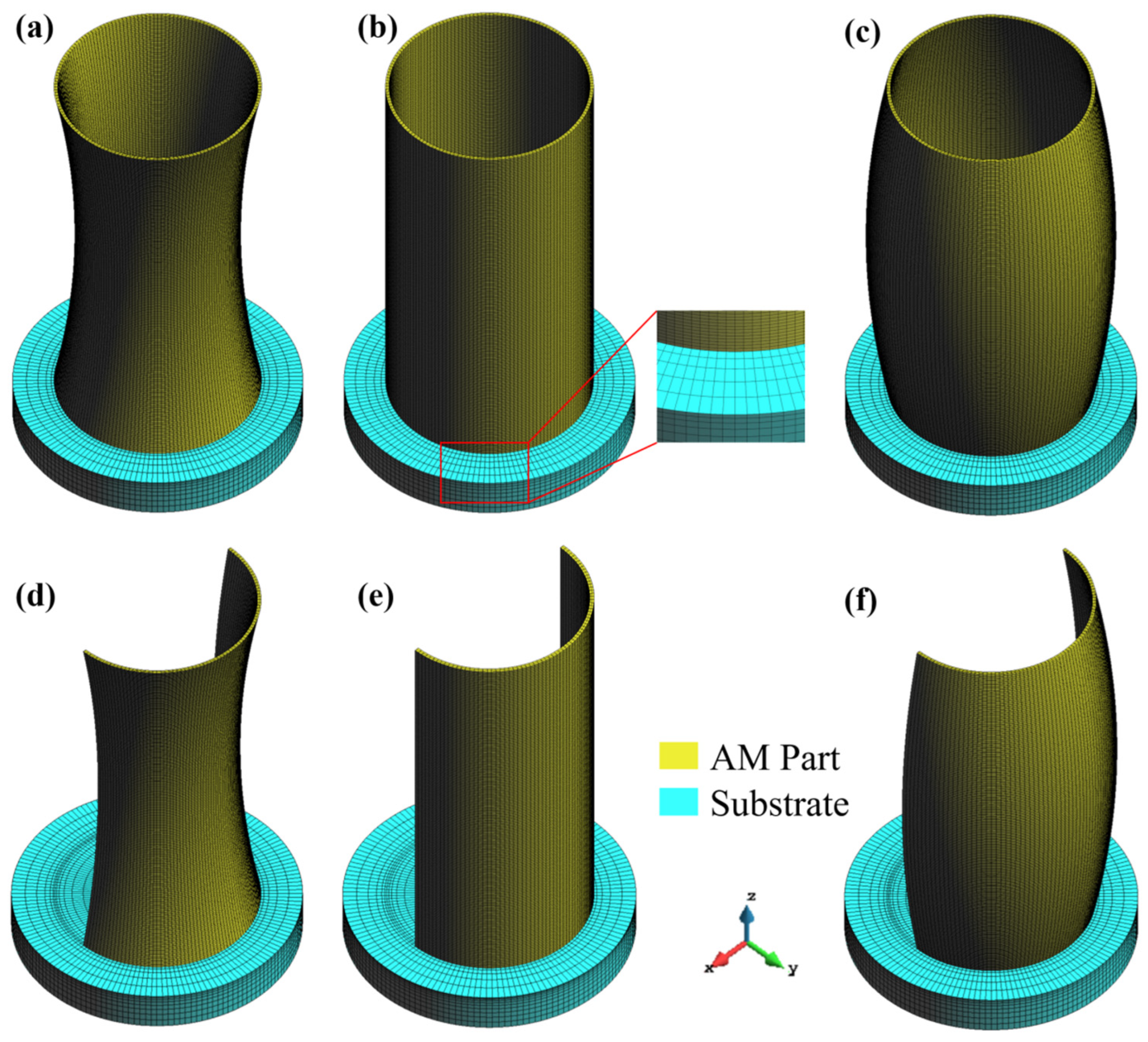
Figure 5 shows the FE meshes of the thin-walled rotating structures. The closed structure is discretized using 79,360 Q1P0 hexahedral elements [40,41] with 115,317 nodes, whereas the open structure consists of 47,360 Q1P0 hexahedral elements and 67,917 nodes. To balance computational efficiency and prediction accuracy, ten physical layers are grouped into a single computational layer. The element size in the deposition region is set to 0.5 mm × 0.5 mm × 0.5 mm, while the mesh is gradually coarsened away from the deposition zone within the substrate. The influence of the substrate is incorporated through equivalent thermo-mechanical boundary conditions. The simulation time for each of the three closed structures is approximately 7.5 h, while the simulation time for the open structure is about 4 h. These computation times reflect the mesh density and model size described above, demonstrating a balance between prediction accuracy and computational efficiency.
The temperature-dependent thermophysical properties of 316L stainless steel powder are listed in Table 3 [42,43,44]. The thermal response during PBF-LB is governed by the balance between laser energy input and heat dissipation, predominantly through conduction into the substrate. Accordingly, the laser power absorption coefficient is set to 45% [45,46], and an equivalent conductive heat transfer coefficient of 1000 W/(m2·°C) is applied at the substrate interface. Heat loss from the top surfaces of the builds occurs through both convection and radiation. The convective heat transfer coefficient is set to 10 W/(m2·°C) with an ambient temperature of 25 °C, while the surface emissivity is taken as 0.5 in the radiation model [42]. During the mechanical analysis, the bottom surface of the substrate is fully constrained, consistent with the experimental setup.

4. Results and Discussion

4.1. Calibration of Thermo-Mechanical Coupled FE Model

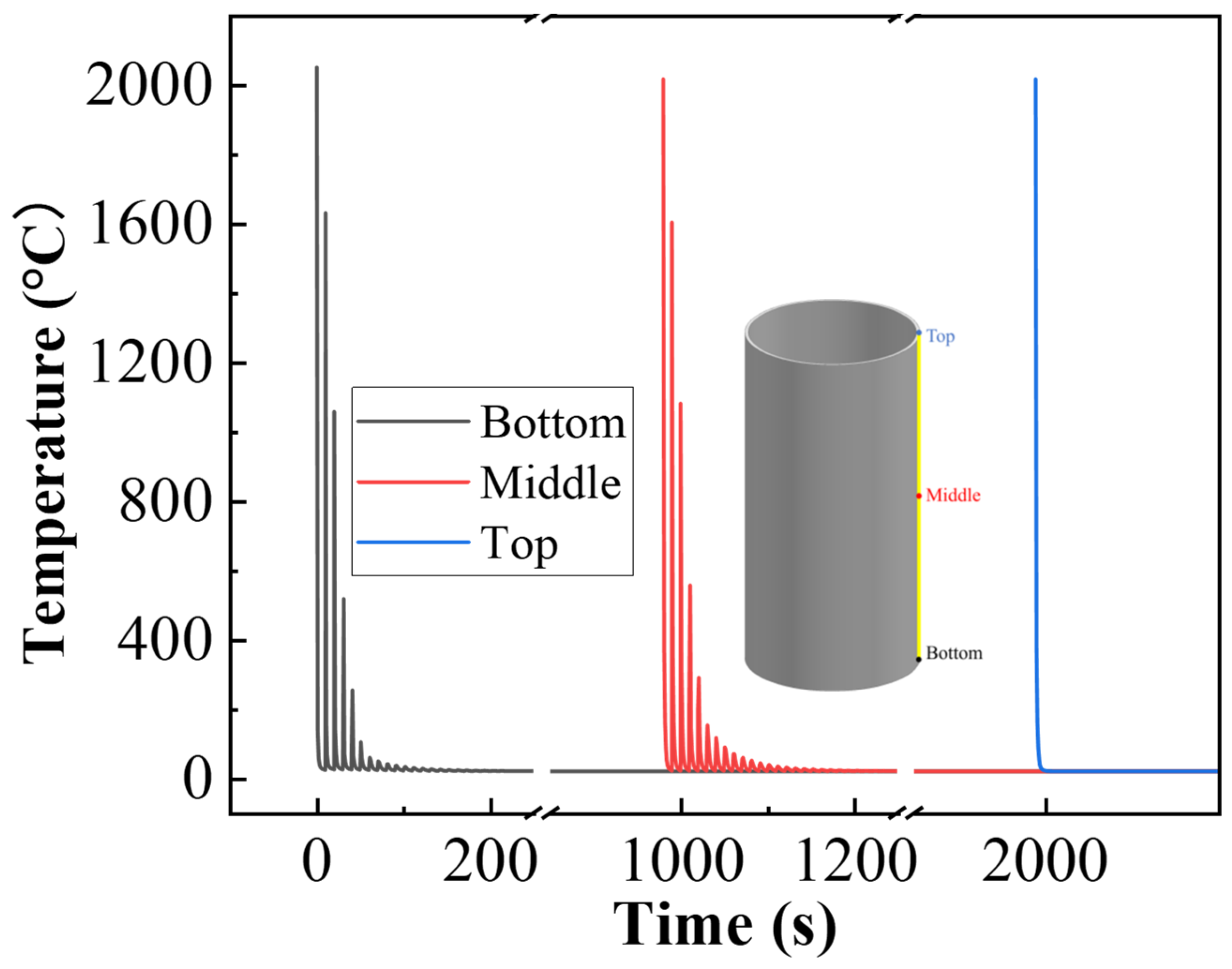
The thermal history of 316L thin-walled rotating structures during the PBF-LB process is first investigated through transient FE thermal simulations, as it directly governs melt pool dynamics and serves as the primary driver of residual stress accumulation and subsequent part distortion. Figure 6 shows the temporal temperature evolution at the bottom, middle, and top regions of the cylindrical shell. During the initial deposition, the bottom region experiences rapid and repetitive heating–cooling cycles. For the first layer, the temperature peaks transiently at approximately 2060 °C before rapidly cooling as the laser moves away, reflecting strong melting–solidification dynamics. With increasing build height, thermal accumulation becomes more pronounced due to reduced substrate heat dissipation, leading to slightly elevated quasi-steady-state peak temperatures around 2000 °C [42,44]. This height-dependent thermal evolution highlights the intrinsic layer-wise heat accumulation in PBF-LB and confirms the variation in thermal histories along the build direction.
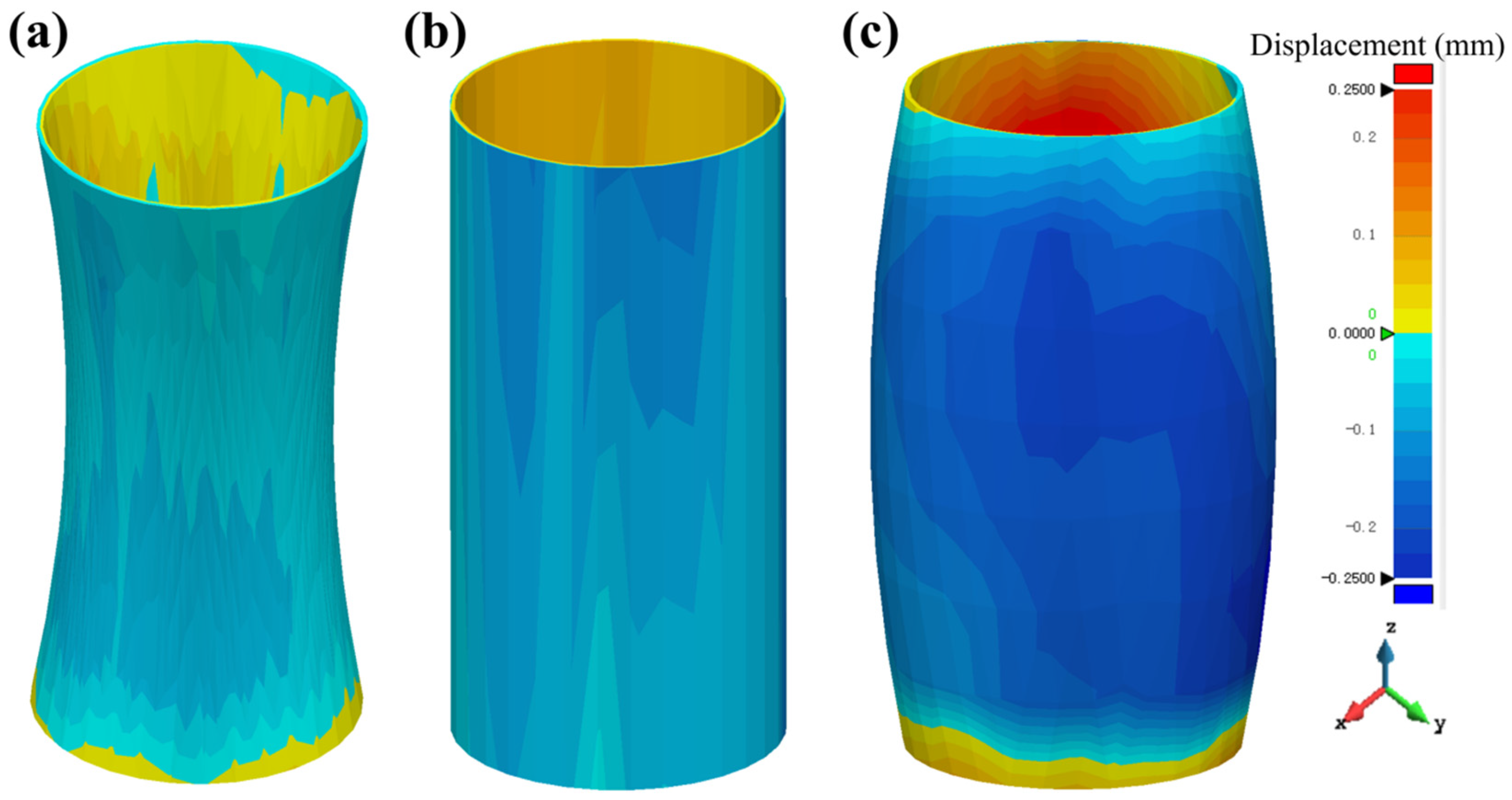
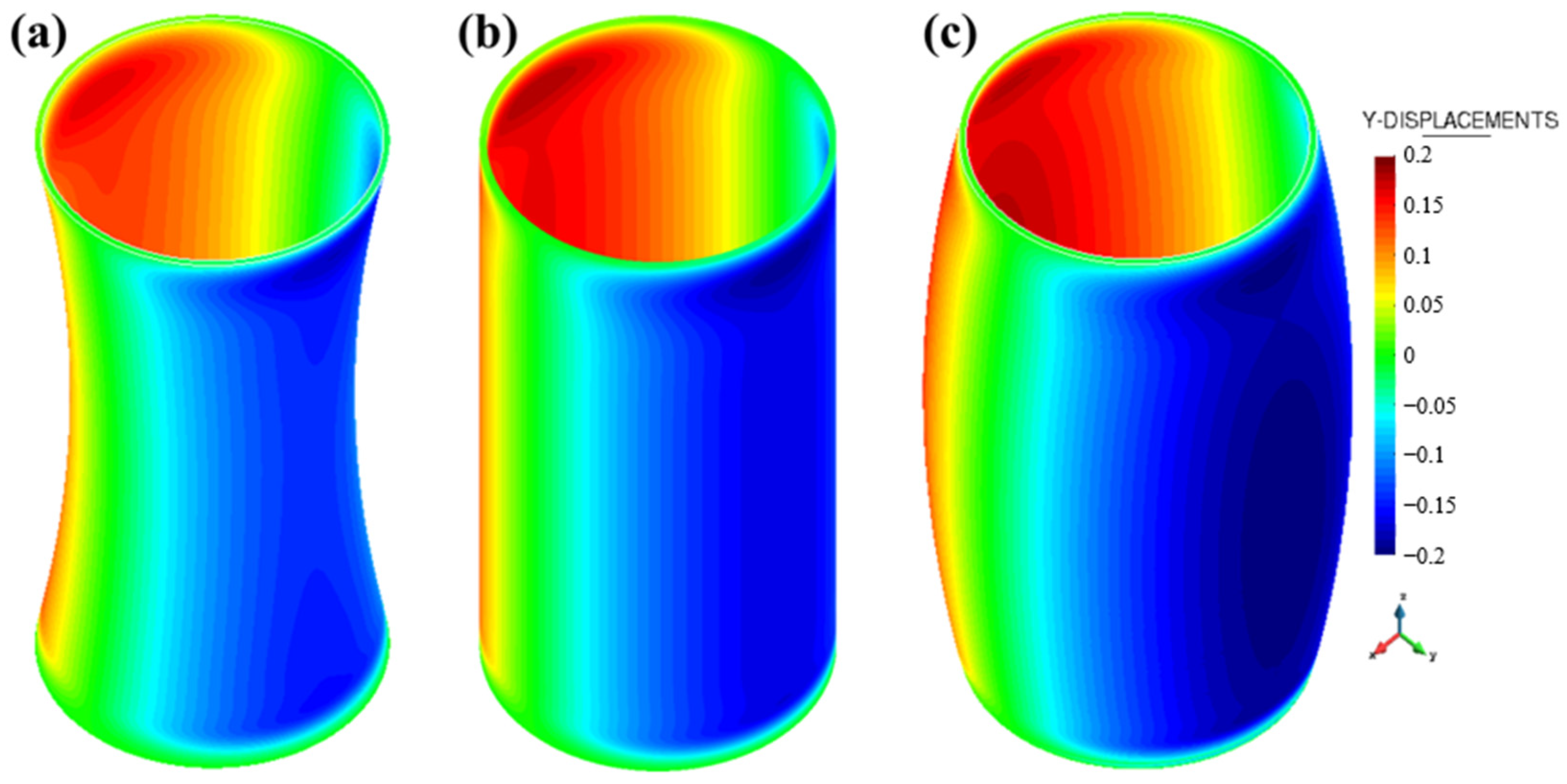
To validate the predictive capability of the developed thermo-mechanically coupled FE model, the simulated deformation fields are quantitatively compared with high-resolution three-dimensional scanning measurements for the three representative rotating thin-walled geometries: dumbbell-shaped, cylindrical, and drum-shaped components. The experimentally measured deformation maps obtained from 3D scanning are shown in Figure 7, where all three geometries exhibit pronounced radial shrinkage following part detachment from the substrate. Corresponding simulation-predicted deformation fields are illustrated in Figure 8. Although all structures exhibit an overall inward radial contraction, distinct differences in deformation magnitude and spatial distribution are observed among the three geometries, reflecting the strong influence of geometric configuration on thermo-mechanical response.
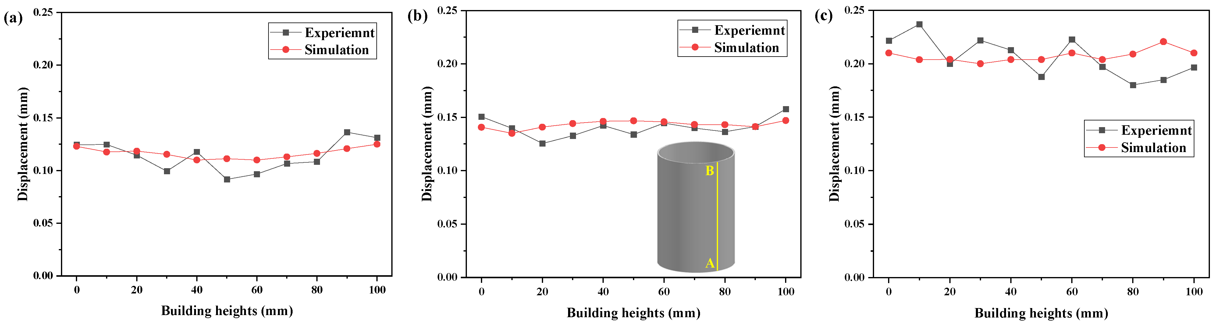
To enable a quantitative comparison, radial deformation profiles along the build direction are extracted from both experimental measurements and numerical simulations at the outer side surfaces of each structure, as shown in Figure 9. For the dumbbell-shaped component (Figure 9a), the experimentally measured deformation ranges from approximately 0.09 to 0.13 mm. The minimum deformation, around 0.09 mm, occurs at the mid-height region corresponding to the reduced cross-sectional diameter of 40 mm. This region exhibits enhanced structural stiffness and geometric constraint, which effectively suppresses thermal shrinkage and results in improved dimensional stability. The numerical simulation reproduces this trend well, predicting a smoother deformation profile with an average shrinkage of approximately 0.12 mm.
For the cylindrical structure (Figure 9b), both experimental measurements and simulation results indicate a nearly uniform radial shrinkage along the build direction, with an average deformation of approximately 0.14 mm. With a constant diameter and uniform wall thickness, the thermal stresses tend to be more uniformly distributed, resulting in stable and consistent shrinkage behavior. In the case of the drum-shaped component (Figure 9c), the deformation magnitude is significantly higher due to the enlarged mid-height diameter, which existed the lower structural stiffness and enhanced stress concentration. The simulated average radial shrinkage reaches approximately 0.21 mm, in close agreement with the experimental measurements.
Overall, the thermo-mechanically coupled FE model accurately captures both the deformation trends and the absolute magnitudes for all three thin-walled rotating geometries. The remaining discrepancies between simulations and experiments primarily stem from measurement uncertainties and modeling simplifications, including the use of constant thermal boundary conditions, an equivalent volumetric heat source representation, and multi-layer activation strategies. Nevertheless, the strong quantitative agreement confirms that the proposed modeling framework provides a reliable and predictive tool for analyzing geometry-dependent thermo-mechanical deformation in PBF-LB-fabricated thin-walled rotating shell structures.

4.2. Effect of Part Size on the Mechanical Evolution

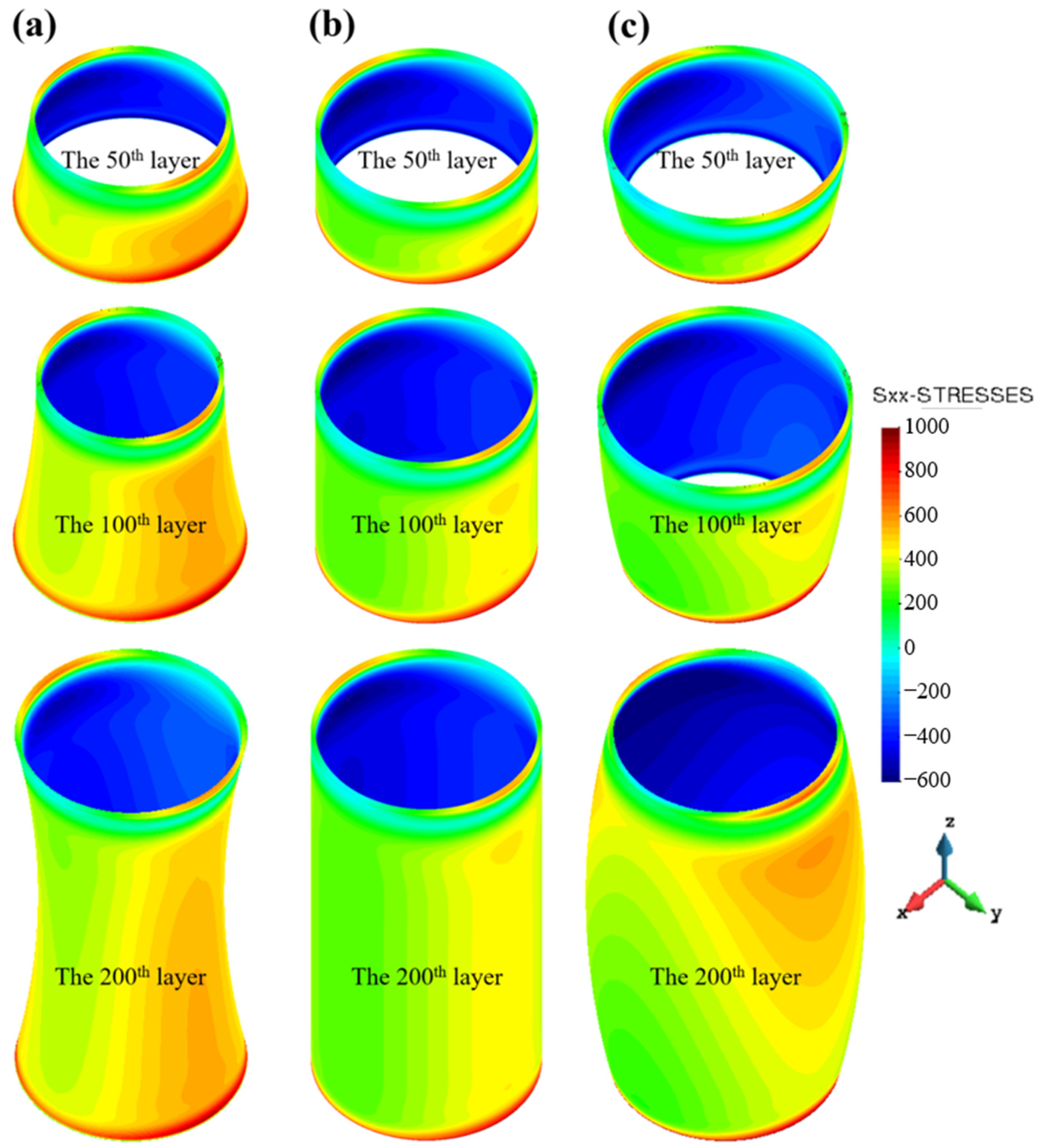
The evolution of residual stress fields in the three thin-walled rotating structures during PBF-LB is shown in Figure 10. Strong stress concentrations consistently occur at the bottom regions, originating from the combined effects of steep thermal gradients imposed by the cold substrate during initial deposition and the mechanical constraints of the rigid base plate. Rapid laser heating and cooling cycles induce a characteristic “inner compression–outer tension” stress state, with compressive stresses on the inner surfaces and tensile stresses on the outer surfaces, which governs the subsequent mechanical evolution.
During the early deposition stage, all structures share the same bottom diameter and therefore experience comparable substrate constraints, resulting in similar initial stress accumulation. As the build progresses and geometric variations become more pronounced, the stress evolution becomes strongly geometry-dependent. The dumbbell-shaped structure, with its inward-converging geometry, develops enhanced structural stiffness that imposes stronger self-constraint on thermal contraction, leading to higher residual stresses during the early-to-middle stages compared with the cylindrical and drum-shaped structures. In contrast, the cylindrical structure maintains a constant diameter along the build direction, promoting more uniform stress redistribution and mitigating excessive localization.
In the middle-to-late stages of printing, the stress evolution of the dumbbell-shaped and drum-shaped structures diverges further due to geometric transitions. The drum-shaped structure progressively exhibits inward-tapering geometry from mid- to top-height, which enhanced the structural stiffness and constraint, driving a gradual increase in residual stresses. Meanwhile, the dumbbell-shaped structure retains relatively high stress levels, as stresses accumulated during early deposition are only partially relaxed. Consequently, the final residual stress magnitudes in both the dumbbell-shaped and drum-shaped structures are significantly higher than in the cylindrical structure. As build height increases, reduced structural stiffness and gradual relaxation of substrate constraint lead to partial stress relaxation. Overall, compressive stresses up to ~600 MPa dominate the inner surfaces [47,48], while tensile stresses of comparable magnitude develop on the outer surfaces.
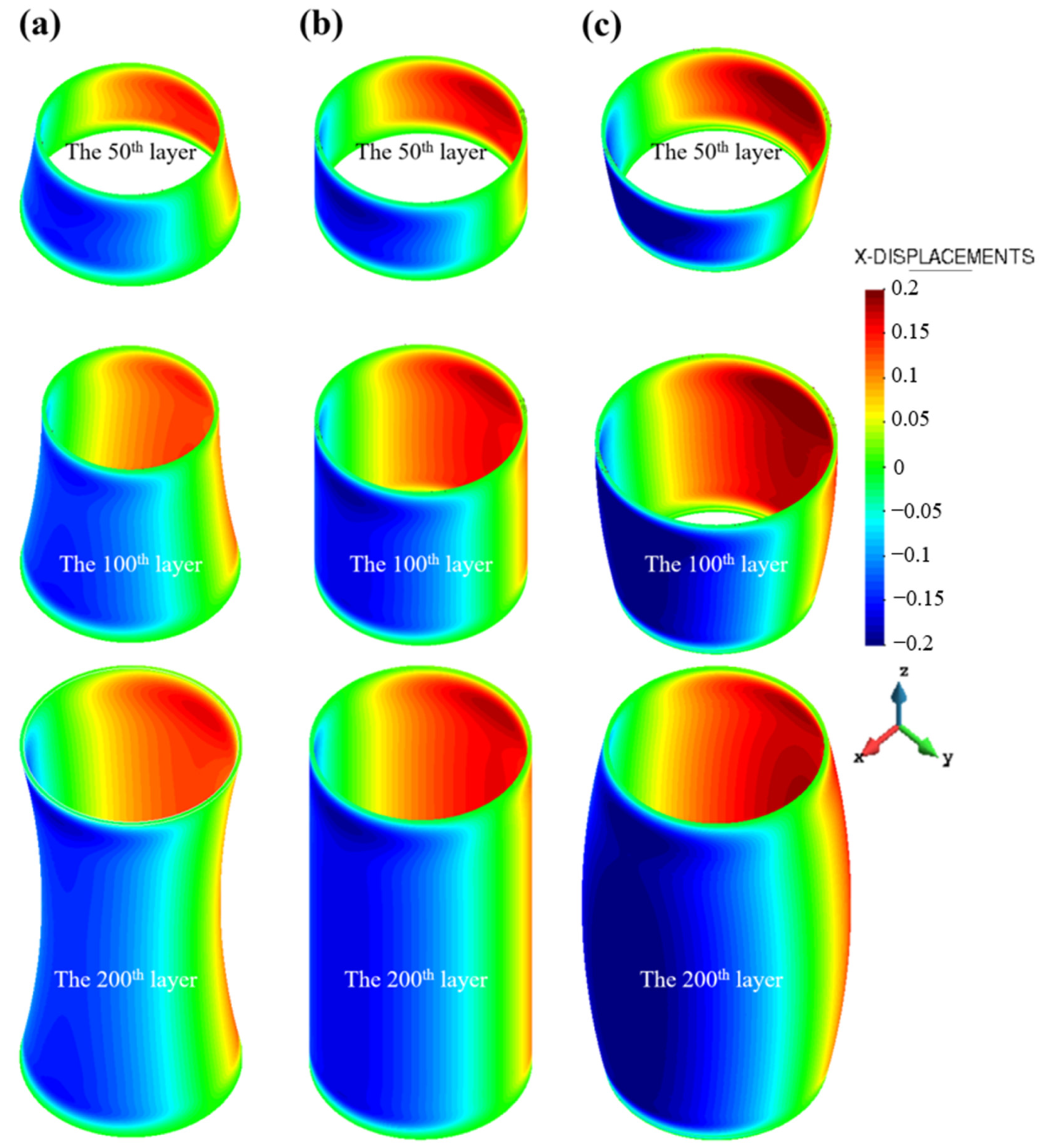
The evolution of radial deformation along the build direction (X-direction) is presented in Figure 11. Consistent with the “inner compression–outer tension” stress state, all three structures exhibit overall inward shrinkage. For the dumbbell-shaped structure, the increasing diameter toward the top amplifies deformation in upper regions. The cylindrical structure, with constant diameter and uniform stiffness, shows relatively stable contraction (~0.15 mm average). In contrast, the drum-shaped structure exhibits non-monotonic deformation, initially increasing and later decreasing, with a peak radial contraction of ~0.21 mm.
A closer examination at identical build heights reveals distinct geometry-dependent deformation mechanisms. During early printing, the drum-shaped structure displays an outward-expanding profile, promoting greater deformation accumulation until the mid-to-late stages, where the geometry transitions to inward-converging, partially reducing contraction. Conversely, the dumbbell-shaped structure develops outward-expanding features mainly in the middle-to-late stages, resulting in delayed but increasing deformation. The cylindrical structure, with invariant geometry, maintains relatively uniform contraction throughout the build.
These observations clearly demonstrate that the thermo-mechanical response of thin-walled rotating structures fabricated by PBF-LB is strongly governed by part size and geometric configuration. Larger or more geometrically complex structures exhibit amplified residual stress accumulation and deformation, emphasizing the critical role of geometry-induced stress amplification and size effects in distortion control.

4.3. Stress-Deformation Evolution of Open Thin-Walled Structures

Open thin-walled structures, characterized by reduced global stiffness and weakened geometric constraints, are more susceptible to deformation induced by residual thermal stresses. To further elucidate the influence of structural stiffness on thermo-mechanical behavior during PBF-LB, this section examines the stress–deformation responses of open structures derived from the three rotating geometries. By comparing the deformation characteristics of open and closed configurations under identical thermal loading conditions, the analysis aims to clarify how stiffness reduction affects deformation magnitude and bulging location, thereby providing mechanistic insights relevant to the design of thin-walled components.
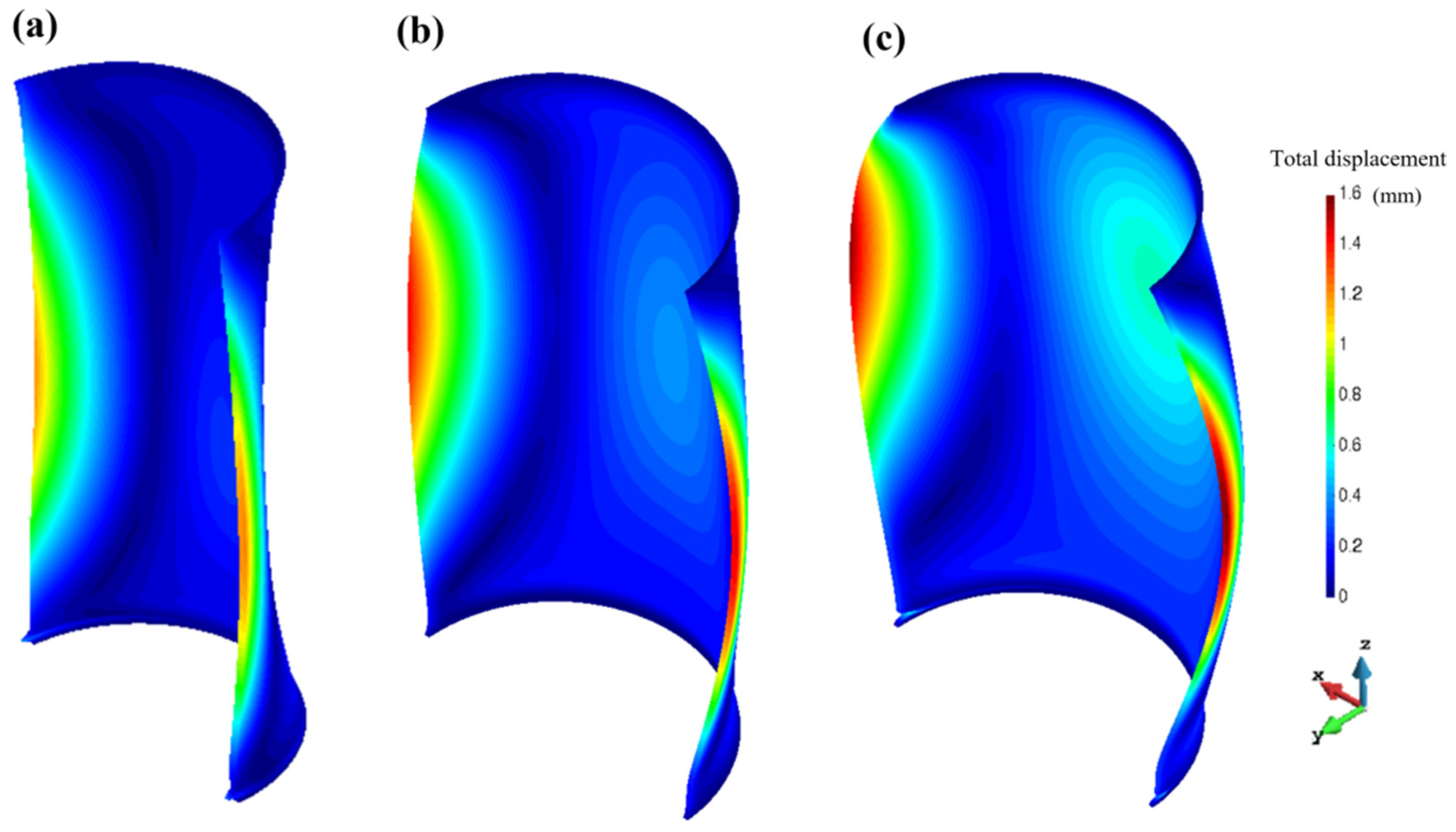
As shown in Figure 12, all configurations display pronounced outward bulging along the lateral surfaces, with deformation magnitudes increasing from ~1.2 mm for the dumbbell-shaped structure to ~1.4 mm for the cylindrical structure, and further to ~1.6 mm for the drum-shaped structure. These results indicate a strong geometry-dependent deformation amplification effect, consistent with the interplay of residual stress and structural compliance. The substrate constraint suppresses deformation in the lower regions, resulting in maximum deformation predominantly concentrated in the mid-to-upper sections of the structures [48].
A clear upward shift in the bulging position is observed with increasing geometric size. The dumbbell-shaped structure, featuring a minimum mid-height diameter corresponding to a relatively stiff region, exhibits the lowest bulging position. In contrast, the cylindrical structure, with uniform diameter along the build direction, shows a moderate upward shift in maximum deformation due to near-uniform stiffness distribution. The drum-shaped structure, characterized by a maximum diameter at mid-height and higher structural compliance, displays the largest deformation and the highest bulging location. These observations indicate that the combination of geometry-induced compliance and substrate constraint governs both the magnitude and vertical localization of deformation in open thin-walled structures.
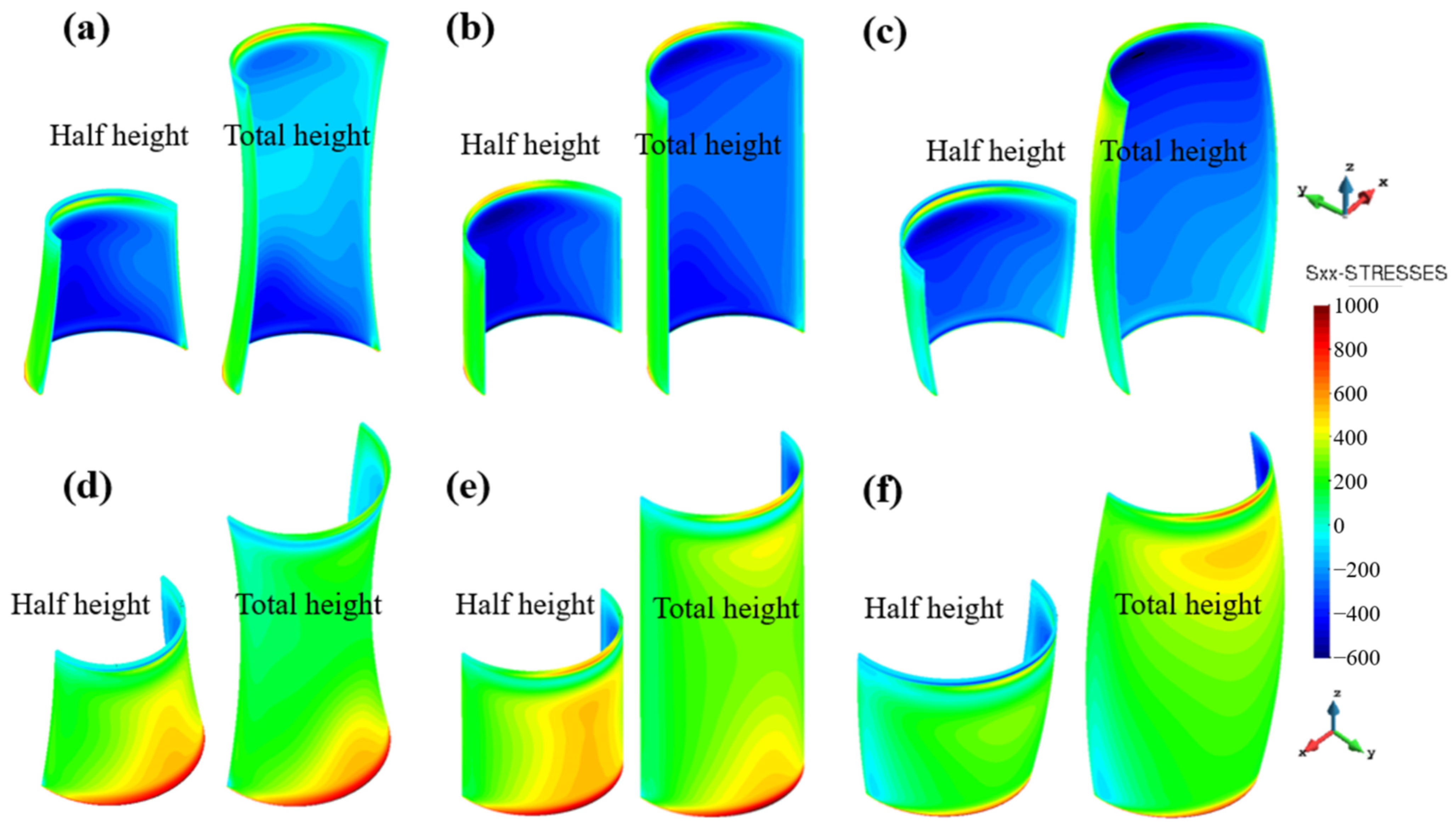
The corresponding longitudinal stress distributions on the inner and outer surfaces are presented in Figure 13. In all cases, compressive stresses dominate the inner surfaces, while tensile stresses prevail on the outer surfaces, driving the observed outward bulging. For the drum-shaped structure, a pronounced minimum tensile stress region appears near the bottom of the outer surface, with high tensile stresses concentrated near the substrate–part interface. Conversely, the dumbbell-shaped and cylindrical structures show gradually decreasing tensile stress along the build direction. As build height increases, tensile stress regions shrink and progressively concentrate toward the substrate, reflecting stress redistribution and partial relaxation in the upper regions.
Overall, these results demonstrate that open thin-walled structures exhibit amplified deformation compared with closed shells, and that both the magnitude and spatial distribution of bulging are strongly controlled by geometric features and substrate constraints. The findings provide mechanistic insights into stress–deformation coupling and highlight the critical importance of geometry-informed design and process planning for distortion mitigation in PBF-LB-fabricated open thin-walled components.

5. Conclusions and Outlook

This study investigates the thermo-mechanical behavior of thin-walled rotating structures fabricated by PBF-LB through a combined experimental–numerical approach. Thermo-mechanically coupled FE simulations, validated by high-precision three-dimensional deformation measurements, are used to quantify temperature evolution, residual stress accumulation, and geometry-dependent distortion in three representative 316L stainless steel geometries. The results show that distortion behavior is strongly governed by structural size and stiffness. Among closed configurations, the drum-shaped structure exhibits the highest residual stress concentration, reaching approximately 600 MPa, and the largest radial contraction of about 0.14 mm, while the dumbbell-shaped and cylindrical structures display smaller and more uniform deformations of approximately 0.09 mm and 0.12 mm. These observations indicate that increased characteristic size combined with reduced stiffness promotes stress concentration and dimensional deviation in thin-walled PBF-LB parts. In open configurations, the reduction in geometric constraint leads to a pronounced amplification of deformation, with the open drum-shaped structure showing the largest out-of-plane displacement of approximately 1.6 mm. Both the magnitude and vertical position of bulging are closely linked to local diameter variation and substrate constraint.
Overall, the results clarify how geometric features, structural size, and stiffness jointly control stress relaxation and shape stability in thin-walled rotating components produced by PBF-LB. The validated modeling framework and geometry-informed insights support distortion-aware design and process planning for thin-walled rotational parts, particularly in aerospace applications such as exhaust nozzles, combustion liners, and lightweight ducting where dimensional accuracy is critical.
Future work aims to improve the efficiency and scalability of distortion prediction for complex thin-walled geometries (e.g., lattice structures, TPMS). The integration of data-driven approaches with physics-based thermo-mechanical models, together with multi-scale modeling and in situ monitoring–assisted model updating, is expected to further enhance predictive robustness and support design iteration in industrial practice.

Author Contributions

Conceptualization, M.T.; Data curation, J.H.; Formal analysis, C.L. and L.Z.; Investigation, M.T., L.Z. and S.C.; Methodology, M.T.; Project administration, X.L.; Resources, L.Z.; Software, J.H. and X.L.; Supervision, L.Z. and X.L.; Validation, C.L., L.Z. and S.C.; Visualization, J.H. and S.C.; Writing—original draft, M.T., C.L. and J.H.; Writing—review & editing, X.L. All authors have read and agreed to the published version of the manuscript.

Funding

This research received no external funding.

Data Availability Statement

The datasets presented in this article are not readily available because the data are part of an ongoing study or due to technical limitations. Requests to access the datasets should be directed to [a345392807@163.com].

Conflicts of Interest

Authors M.T. and C.L. were employed by Hunan Gaochuang Xiangyu Equipment Technology Co., Ltd. The remaining authors declare that the research was conducted in the absence of any commercial or financial relationships that could be construed as a potential conflict of interest.

References

  1. Gibson, I.; Rosen, D.; Stucker, B. Additive Manufacturing Technologies: 3D Printing, Rapid Prototyping, and Direct Digital Manufacturing; Springer: New York, NY, USA, 2015. [Google Scholar] [CrossRef] [Scilit]
  2. Orme, M.; Madera, I.; Gschweitl, M.; Ferrari, M. Topology Optimization for Additive Manufacturing as an Enabler for Light Weight Flight Hardware. Designs 2018, 2, 51. [Google Scholar] [CrossRef] [Scilit]
  3. Madaj, R.; Kohar, R.; Brumercik, F.; Veres, M. Design Study of Hole Types for Improved Cooling of Experimental Heatsinks Manufactured by SLM Technology Using an AlSi10Mg Alloy. Appl. Sci. 2025, 15, 2118. [Google Scholar] [CrossRef] [Scilit]
  4. Cheng, L.; Liang, X.; Bai, J.; Chen, Q.; Lemon, J.; To, A. On utilizing topology optimization to design support structure to prevent residual stress induced build failure in laser powder bed metal additive manufacturing. Addit. Manuf. 2019, 27, 290–304. [Google Scholar] [CrossRef] [Scilit]
  5. Nguyen, P.C.H.; Kim, Y.; Choi, Y. Lightweight design with metallic additively manufactured cellular structures. J. Comput. Des. Eng. 2022, 9, 155–167. [Google Scholar] [CrossRef] [Scilit]
  6. Zheng, M.; Wei, L.; Chen, J.; Zhang, Q.; Zhong, C.; Lin, X.; Huang, W. A novel method for the molten pool and porosity formation modelling in selective laser melting. Int. J. Heat Mass Transf. 2019, 140, 1091–1105. [Google Scholar] [CrossRef] [Scilit]
  7. Mercelis, P.; Kruth, J. Residual stresses in selective laser sintering and selective laser melting. Rapid Prototyp. J. 2006, 12, 254–265. [Google Scholar] [CrossRef] [Scilit]
  8. Bian, P.; Jammal, A.; Xu, K.; Ye, F.; Zhao, N.; Song, Y. A Review of the Evolution of Residual Stresses in Additive Manufacturing During Selective Laser Melting Technology. Materials 2025, 18, 1707. [Google Scholar] [CrossRef] [Scilit]
  9. Vora, P.; Mumtaz, K.; Todd, I.; Hopkinson, N. AlSi12 in-situ alloy formation and residual stress reduction using anchorless selective laser meltingAlSi12. Addit. Manuf. 2015, 7, 12–19. [Google Scholar] [CrossRef] [Scilit]
  10. Yadroitsev, I.; Yadroitsava, I. Evaluation of residual stress in stainless steel 316L and Ti6Al4V samples produced by selective laser melting. Virtual Phys. Prototyp. 2015, 10, 67–76. [Google Scholar] [CrossRef] [Scilit]
  11. Lu, Y.; Wu, S.; Gan, Y.; Huang, T.; Yang, C.; Junjie, L.; Lin, J. Study on the microstructure, mechanical property and residual stress of SLM Inconel-718 alloy manufactured by differing island scanning strategy. Opt. Laser Technol. 2015, 75, 197–206. [Google Scholar] [CrossRef] [Scilit]
  12. Abele, E.; Stoffregen, H.A.; Kniepkamp, M.; Lang, S.; Hampe, M. Selective laser melting for manufacturing of thin-walled porous elements. J. Mater. Process. Technol. 2015, 215, 114–122. [Google Scholar] [CrossRef] [Scilit]
  13. Chakraborty, A.; Tangestani, R.; Batmaz, R.; Muhammad, W.; Plamondon, P.; Wessman, A.; Yuan, L.; Martin, É. In-process failure analysis of thin-wall structures made by laser powder bed fusion additive manufacturing. J. Mater. Sci. Technol. 2022, 98, 233. [Google Scholar] [CrossRef] [Scilit]
  14. Jagatheeshkumar, S.; Raguraman, M.; Prasad, A.V.S.S.; Nagesha, B.K.; Chandrasekhar, U. Simulation driven methodology for distortion prediction in thin-walled compressor blade built using LPBF process. Int. J. Interact. Des. Manuf. 2025, 19, 1633–1646. [Google Scholar] [CrossRef] [Scilit]
  15. Salvi, D.; Ucciardello, N.; Vesco, S. Multi-head MEX 3D printing of self-recoverable joule-heating-based shape memory polymeric components. Arab. J. Sci. Eng. 2025. [Google Scholar] [CrossRef] [Scilit]
  16. Calignano, F.; Cattano, G.; Manfredi, D. Manufacturing of thin wall structures in AlSi10Mg alloy by laser powder bed fusion through process parameters. J. Mater. Process. Technol. 2018, 255, 773–783. [Google Scholar] [CrossRef] [Scilit]
  17. Cai, G.; Liu, H.; Peng, K.; Wang, B.; Hu, B. Orthogonal experimental method to investigate the effect of process parameters on the mechanical properties of thin-walled parts by PBF-LB/M. Sci. Rep. 2024, 14, 19776. [Google Scholar] [CrossRef] [Scilit]
  18. Zhao, Y.; Tian, W.; Liu, J.; Qian, D.; Meng, W.; Wang, J. Laser Additive Manufacturing of 316L Stainless Steel Thin-wall Ring Parts. Fluid Dyn. Mater. Process. 2023, 19, 451–470. [Google Scholar] [CrossRef] [Scilit]
  19. Buchbinder, D.; Meiners, W.; Pirch, N.; Wissenbach, K.; Schrage, J. Investigation on reducing distortion by preheating during manufacture of aluminum components using selective laser melting. J. Laser Appl. 2013, 26, 012004. [Google Scholar] [CrossRef] [Scilit]
  20. Lu, X.; Lin, X.; Chiumenti, M.; Cervera, M.; Hu, Y.; Ji, X.; Ma, L.; Yang, H.; Huang, W. Residual stress and distortion of rectangular and S-shaped Ti-6Al-4V parts by Directed Energy Deposition: Modelling and experimental calibration. Addit. Manuf. 2019, 26, 166–179. [Google Scholar] [CrossRef] [Scilit]
  21. Cao, J.; Gharghouri, M.A.; Nash, P. Finite-element analysis and experimental validation of thermal residual stress and distortion in electron beam additive manufactured ti-6Al-4V build plates. J. Mater. Process. Technol. 2016, 237, 409–419. [Google Scholar] [CrossRef] [Scilit]
  22. Lu, X.; Chiumenti, M.; Cervera, M.; Tan, H.; Lin, X.; Wang, S. Warpage Analysis and Control of Thin-Walled Structures Manufactured by Laser Powder Bed Fusion. Metals 2021, 11, 686. [Google Scholar] [CrossRef] [Scilit]
  23. Ding, J.; Qu, S.; Zhang, L.; Wang, M.Y.; Song, X. Geometric deviation and compensation for thin-walled shell lattice structures fabricated by high precision laser powder bed fusion. Addit. Manuf. 2022, 58, 103061. [Google Scholar] [CrossRef] [Scilit]
  24. Chen, C.; Xiao, Z.; Zhu, H.; Zeng, X. Deformation and control method of thin-walled part during laser powder bed fusion of ti–6Al–4V alloy. Int. J. Adv. Manuf. Technol. 2020, 110, 3467–3478. [Google Scholar] [CrossRef] [Scilit]
  25. Hussain, A.; Lee, J.; Kim, R.E.; Kim, H.S.; Ha, J.; Kwon, Y.S.; Kim, D. Fabrication of robust high-aspect-ratio ti-6Al-4V ultra-thin-walled structures using powder bed fusion with in-situ focused infrared heating. Addit. Manuf. 2025, 109, 104867. [Google Scholar] [CrossRef] [Scilit]
  26. Wu, Z.; Narra, S.P.; Rollett, A. Exploring the fabrication limits of thin-wall structures in a laser powder bed fusion process. Int. J. Adv. Manuf. Technol. 2020, 110, 191–207. [Google Scholar] [CrossRef] [Scilit]
  27. Ahmed, N.; Barsoum, I.; Al-Rub, R.K.A. Numerical investigation of residual stresses in thin-walled additively manufactured structures from selective laser melting. Heliyon 2023, 9, e19385. [Google Scholar] [CrossRef] [Scilit]
  28. Jia, H.; Sun, H.; Wang, H.; Wu, Y.; Wang, H. Size effect in selective laser melting additive manufacturing of 700 mm large component. J. Manuf. Process. 2022, 75, 125–137. [Google Scholar] [CrossRef] [Scilit]
  29. Roach, A.M.; White, B.C.; Garland, A.; Jared, B.H.; Carroll, J.D.; Boyce, B.L. Size-dependent stochastic tensile properties in additively manufactured 316L stainless steel. Addit. Manuf. 2020, 32, 101090. [Google Scholar] [CrossRef] [Scilit]
  30. Leicht, A.; Pauzon, C.; Rashidi, M.; Klement, U.; Nyborg, L.; Hryha, E. Effect of part thickness on the microstructure and tensile properties of 316L parts produced by laser powder bed fusion. Adv. Ind. Manuf. Eng. 2021, 2, 100037. [Google Scholar] [CrossRef] [Scilit]
  31. Zhang, A.; Qi, B.; Shi, B.; Li, D. Effect of curvature radius on the residual stress of thin-walled parts in laser direct forming. Int. J. Adv. Manuf. Technol. 2015, 79, 81–88. [Google Scholar] [CrossRef] [Scilit]
  32. Papadakis, L.; Hauser, C. Experimental and computational appraisal of the shape accuracy of a thin-walled virole aero-engine casing manufactured by means of laser metal deposition. Prod. Eng. 2017, 11, 389–399. [Google Scholar] [CrossRef] [Scilit]
  33. Riener, K.; Oswald, S.; Winkler, M.; Leichtfried, G.J. Influence of storage conditions and reconditioning of AlSi10Mg powder on the quality of parts produced by laser powder bed fusion (LPBF). Addit. Manuf. 2021, 39, 101896. [Google Scholar] [CrossRef] [Scilit]
  34. Kim, T.; Kim, M.-K.; Fang, Y.; Suhr, J. Moisture effects on qualities and properties of laser powder bed fusion (LPBF) additive manufacturing of as-built 17-4PH stainless steel parts. Metals 2023, 13, 1550. [Google Scholar] [CrossRef] [Scilit]
  35. Chiumenti, M.; Cervera, M.; Salmi, A.; De Saracibar, C.A.; Dialami, N.; Matsui, K. Finite element modeling of multi-pass welding and shaped metal deposition processes. Comput. Methods Appl. Mech. Eng. 2010, 199, 2343–2359. [Google Scholar] [CrossRef] [Scilit]
  36. Lu, X.; Chiumenti, M.; Cervera, M.; Zhang, G.; Lin, X. Mitigation of residual stresses and microstructure homogenization in directed energy deposition processes. Eng. Comput. 2022, 38, 4771–4790. [Google Scholar] [CrossRef] [Scilit]
  37. Chen, Q.; Liang, X.; Hayduke, D.; Liu, J.; Cheng, L.; Oskin, J.; Whitmore, R.; To, A.C. An inherent strain based multiscale modeling framework for simulating part-scale residual deformation for direct metal laser sintering. Addit. Manuf. 2019, 28, 406–418. [Google Scholar] [CrossRef] [Scilit]
  38. Lu, X.; Lin, X.; Chiumenti, M.; Cervera, M.; Hu, Y.; Ji, X.; Ma, L.; Huang, W. In situ measurements and thermo-mechanical simulation of ti–6Al–4V laser solid forming processes. Int. J. Mech. Sci. 2019, 153–154, 119–130. [Google Scholar] [CrossRef] [Scilit]
  39. Chiumenti, M.; Cervera, M.; De Saracibar, C.A.; Dialami, N. Numerical modeling of friction stir welding processes. Comput. Methods Appl. Mech. Eng. 2013, 254, 353–369. [Google Scholar] [CrossRef] [Scilit]
  40. The Finite Element Method. 2024. Available online: https://shop.elsevier.com/books/the-finite-element-method/zienkiewicz/978-0-443-16044-8 (accessed on 21 January 2026).
  41. Kadapa, C. Mixed displacement–pressure formulations and suitable finite elements for multimaterial problems with compressible and incompressible models. Comput. Methods Appl. Mech. Eng. 2024, 432, 117354. [Google Scholar] [CrossRef] [Scilit]
  42. Sotiriou, M.P.P.; Aristeidakis, J.S.S.; Tzini, M.-I.T.T.; Papadioti, I.; Haidemenopoulos, G.N.; Aravas, N.; Sotiriou, M.P.P.; Aristeidakis, J.S.S.; Tzini, M.-I.T.T.; Papadioti, I.; et al. Microstructural and thermomechanical simulation of the additive manufacturing process in 316L austenitic stainless steel. Mater. Proc. 2021, 3, 20. [Google Scholar] [CrossRef] [Scilit]
  43. Bogaard, R.H.; Desai, P.D.; Li, H.H.; Ho, C.Y. Thermophysical properties of stainless steels. Thermochim. Acta 1993, 218, 373–393. [Google Scholar] [CrossRef] [Scilit]
  44. Fetni, S.; Enrici, T.M.; Niccolini, T.; Tran, H.S.; Dedry, O.; Duchêne, L.; Mertens, A.; Habraken, A.M. Thermal model for the directed energy deposition of composite coatings of 316L stainless steel enriched with tungsten carbides316L. Mater. Des. 2021, 204, 109661. [Google Scholar] [CrossRef] [Scilit]
  45. Trapp, J.; Rubenchik, A.M.; Guss, G.; Matthews, M.J. In situ absorptivity measurements of metallic powders during laser powder-bed fusion additive manufacturing. Appl. Mater. Today 2017, 9, 341–349. [Google Scholar] [CrossRef] [Scilit]
  46. Mahmood, M.A.; Ishfaq, K.; Oane, M.; Liou, F. Porosity prediction in LPBF of AISI 316L stainless steel: Refined volumetric energy density and FEM simulation approach. Opt. Laser Technol. 2025, 188, 113015. [Google Scholar] [CrossRef] [Scilit]
  47. Smith, W.L.; Roehling, J.D.; Strantza, M.; Ganeriwala, R.K.; Ashby, A.S.; Vrancken, B.; Clausen, B.; Guss, G.M.; Brown, D.W.; McKeown, J.T.; et al. Residual stress analysis of in situ surface layer heating effects on laser powder bed fusion of 316L stainless steel. Addit. Manuf. 2021, 47, 102252. [Google Scholar] [CrossRef] [Scilit]
  48. Evans, A.; Schröder, J.; Pirling, T.; Ulbricht, A.; Ocaño, P.S.; Bruno, G. Resolving the subsurface residual stress maximum in laser powder bed-fused 316L stainless steel by diffraction-based analysis. JOM 2025, 77, 9726–9737. [Google Scholar] [CrossRef] [Scilit]
Figure 1. (a) SEM image and (b) Particle Size Distribution (PSD) plot for 316L stainless steel powder.
Jmmp 10 00072 g001
Figure 2. CAD models and geometric dimensions of the three different rotating thin-walled structures.
Jmmp 10 00072 g002
Figure 3. Three thin-walled parts printed by PBF-LB.
Jmmp 10 00072 g003
Figure 4. Using 3D scanner to measure part deformation.
Jmmp 10 00072 g004
Figure 5. FE meshes of rotating thin-walled structures: (a) dumbbell part; (b) cylinder part; (c) drum part; (d) semi-dumbbell part; (e) semi-cylinder part; (f) semi-drum part.
Jmmp 10 00072 g005
Figure 6. Temporal evolution of temperature at bottom, middle, and top of the cylindrical part.
Jmmp 10 00072 g006
Figure 7. Contour-filled displacement maps of the side surfaces of different thin-walled structures: (a) dumbbell part; (b) cylinder part; (c) drum part.
Jmmp 10 00072 g007
Figure 8. The simulated deformation of different thin-walled structures: (a) dumbbell part; (b) cylinder part; (c) drum part.
Jmmp 10 00072 g008
Figure 9. Comparison between simulated and measured deformation (along the building direction): (a) dumbbell part; (b) cylinder part; (c) drum part.
Jmmp 10 00072 g009
Figure 10. Stress field evolution of three types of rotating structures: (a) dumbbell part; (b) cylinder part; (c) drum part.
Jmmp 10 00072 g010
Figure 11. Deformation evolution of three types of rotating structures: (a) dumbbell part; (b) cylinder part; (c) drum part.
Jmmp 10 00072 g011
Figure 12. Deformation comparison of three types of open thin-walled structures: (a) dumbbell part; (b) cylinder part; (c) drum part.
Jmmp 10 00072 g012
Figure 13. Longitudinal stress evolution on inner face of: (a) dumbbell part; (b) cylinder part; (c) drum part; and outer face of (d) dumbbell part; (e) cylinder part; (f) drum part.
Jmmp 10 00072 g013
Table 1. The chemical composition of the 316L stainless steel powder.
ElementFeMoCrNiSPMnSiC
wt.%Bal.2.6018.1913.570.0050.0211.360.520.018
Table 2. Process parameters used for the PBF-LB process.
Laser Power (W)Layer Thickness (mm)Scan Speed (mm/s)Hatch Distance (μm)Laser Beam Diameter (μm)Energy Density
(J/mm3)
2600.0590010010057.8
Table 3. Temperature-dependent material properties of 316L stainless steel [42,43,44].
Temperature (°C)Density (kg/m3)Thermal Conductivity (W/(m·°C))Heat Capacity (J/(kg·°C))Poisson’s RatioThermal Expansion Coefficient (μm/m/°C)Young’s Modulus (GPa)Elastic Limit (MPa)
20793013.55000.2513.4195220
125782815.55130.2315.2190217
525763520.85510.31921.4162145
925748326.25890.2426.711373
1125741528.86130.2429.37318
1245741530.46330.2430.65115
1370736032.16700.2432.45115
14507230358800.2433.45115
16006743378800.2435.35115
27006730389690.2449.15115
Disclaimer/Publisher’s Note: The statements, opinions and data contained in all publications are solely those of the individual author(s) and contributor(s) and not of MDPI and/or the editor(s). MDPI and/or the editor(s) disclaim responsibility for any injury to people or property resulting from any ideas, methods, instructions or products referred to in the content.