Article

Wire Directed Energy Deposition Additive Manufacturing: Enabling On-Demand Medical Device Injection Mold Repurposing in Pandemic and Healthcare Supply Challenges

by
Leonidas Gargalis
1,
Evangelia K. Karaxi
1,* and
Elias P. Koumoulos
2,*
1
Conify, P. Nikolaidi 23A, Agios Ioannis Rentis, 182 33 Athens, Greece
2
IRES—Innovation in Research Engineering Solutions, Silversquare Europe Square de Meeus 35, 1000 Brussels, Belgium
*
Authors to whom correspondence should be addressed.
J. Manuf. Mater. Process. 2026, 10(2), 63; https://doi.org/10.3390/jmmp10020063
Submission received: 31 December 2025 / Revised: 4 February 2026 / Accepted: 5 February 2026 / Published: 12 February 2026

Abstract

The COVID-19 pandemic critically emphasized the need for rapid, flexible, and decentralized manufacturing solutions to support the urgent demand for essential medical equipment, such as oximeters. Metal wire directed energy deposition—w-DED, also known as w-LMD (wire laser metal deposition)—combines the benefits of high material utilization, increased printing speed, and reduced waste, making it an attractive alternative to traditional powder-based processes, especially under time-sensitive and resource-constrained conditions. This work presents a case study focusing on the design and fabrication of injection molds for oximeter casings using metal-wire-based DED. Martensitic stainless steel AISI-420 wire was employed as feedstock and processed via laser wire additive manufacturing to produce a robust, near-net-shape mold suitable for plastic injection molding. The material was selected due to good corrosion and wear resistance. However, poor ductility and toughness, together with AM-induced anisotropy, were the main challenges to address. Therefore, a multi-step methodology was defined to study the effect of different process parameters, which was validated through printing trials, and the optimum process parameter set was identified. The process enabled the rapid construction of intricate mold geometries, minimizing lead times and allowing for quick design iterations. Microstructural and physical properties such as microhardness of the as-built molds were thoroughly characterized. This case study not only illustrates the technical feasibility of producing functional injection molds via metal w-DED but also outlines its role as a resilient manufacturing pathway, capable of meeting emergent healthcare needs and supporting broader industrial applications in a post-pandemic context.

1. Introduction

1.1. Background and Motivation

The mold and die manufacturing industry is characterized by demanding requirements, including the use of high-strength alloys, the need for micron-level precision, the production of complex geometries, and the pressure to reduce costs while accelerating production cycles [1,2]. These factors have led to a conservative approach among manufacturers, who often hesitate to adopt new technologies unless integration is straightforward and risk is minimized. Metal additive manufacturing (AM) offers transformative potential for mold and die applications, but its adoption has been hindered by high initial investment costs, implementation challenges, and the necessity for specialized post-processing workflows [3,4,5]. Despite the recognized benefits of AM in mold making, such as conformal cooling channels and enhanced thermal management in mold inserts, widespread adoption remains limited [6,7,8,9,10]. The industry relies on a restricted set of established alloys, necessitating the development of equivalent powdered materials for AM processes [11,12,13]. Additionally, post-processing steps, including part separation, milling, and surface finishing, are critical to achieving the required precision and surface quality.
In light of these challenges, the COVID-19 pandemic further underscored the fragility of global supply chains and the urgent need for agile, decentralized manufacturing solutions capable of responding to sudden surges in demand for critical medical equipment. The following sections examine the specific disruptions experienced during the pandemic, the strategic advantages of wire-based directed energy deposition (w-DED) as an alternative to powder-based additive manufacturing, and the role of hybrid manufacturing in enhancing production efficiency and sustainability. These considerations form the foundation for the present study, which investigates the feasibility of employing w-DED with AISI 420 martensitic stainless steel wire for the rapid fabrication of functional injection mold inserts used in the production of pulse oximeter housings. Rather than providing a comparative benchmarking of manufacturing technologies, this work presents a focused case study that demonstrates the end-to-end deployment of w-DED under real-world emergency conditions. The study integrates rapid process optimization, hybrid post-processing, and functional validation through industrial-scale injection molding, offering a practical model for how w-DED can be mobilized effectively in time-critical, resource-constrained scenarios. In this context, the novelty lies not in the isolated use of w-DED for tooling—which is established—but in its application as a resilient and responsive manufacturing pathway for medical tooling during a public health crisis, addressing material availability, speed, and functional performance in a unified framework.

1.2. Supply Chain Disruptions in Material Sourcing During COVID-19

The COVID-19 pandemic exposed significant weaknesses in the global metal powder supply chain essential for additive manufacturing (AM), especially for critical tooling applications. The imPURE project [14] highlighted how issues in the availability, consistency, and timely procurement of AM tool steel powders, such as H13, P20, and 420 stainless steel, threatened emergency production feasibility. Before the pandemic, the metal powder sector grew steadily, driven by the automotive, aerospace, medical, and tooling sectors, but 2020’s disruptions resulted in a sharp decline as factory shutdowns and logistical challenges created volatility in both demand and supply. Automotive manufacturing, which uses more than 70% of metal powder, faced abrupt stoppages that suppressed feedstock demand. Shutdowns in key regions like Hubei, China, led to upstream delays and global shortages, undermining supplier responsiveness and reliability.
From May 2020 to January 2021, attempts to source tool steel powders exclusively from EU suppliers to minimize pandemic delays encountered obstacles: suppliers were inconsistent in their responsiveness due to remote work and staffing shortages, stock levels fluctuated with irregular production and shipping, and obtaining P20 powder often meant waiting lists with uncertain timelines. Minimum Order Quantities (MOQs) made some powders impractical for emergency small-lot manufacturing, while available powders could be more expensive or subject to delays. Additional complications stemmed from technical documentation: supplier data on particle size, chemistry, and mechanical properties varied, making comparisons difficult and requiring time-consuming in-house testing. Suitability for different AM processes (like PBF or DED) varied, sometimes requiring extra pre-processing. The lack of clear, AM-specific standards compounded these issues, and OEMs’ proprietary material systems further limited flexibility. More broadly, the pandemic highlighted the problems of vertical integration, closed-loop material ecosystems, and the absence of robust standards for feedstock verification, powder lifecycle management, and recycled powder assessment. Despite these challenges, the pandemic reinforced AM’s value as a rapid-response technology. While metal AM was not the primary method for COVID-19-related medical products, its use for rapid tooling—such as AM-produced injection molding tools for PPE—demonstrated its potential. However, success relied on access to quality-assured powder, a dependency that proved problematic. These experiences underscore the need for robust, standardized, and transparent supply networks. Lessons from the imPURE project point to the importance of improved powder standardization, diversified EU-based supply, and clearer verification protocols for future resilience.

1.3. Wire-Based DED as a Resilient Alternative

Given these procurement realities, wire-fed directed energy deposition (DED) emerges as a strong alternative to powder-based AM, particularly for rapid tooling and time-critical manufacturing. Wire feedstock, already governed by well-established industrial standards, is sourced from the mature welding sector with clear purchasing specifications, broad supplier networks, and straightforward verification systems. This maturity provides predictable supplies even under crisis conditions and decreases the administrative complexities found in powder procurement, such as reconciling variable datasheets or filling gaps in reported properties. Wire handling and process reliability further differentiate it from powder; wire eliminates concerns about particle size, flowability, or moisture uptake, simplifying storage and focusing quality checks on chemistry and cleanliness. As a result, the path from receipt to production is compressed—an advantage for urgent needs. Wire-fed DED also avoids the procurement inflexibility found in powder-based AM, where vertically integrated OEM systems often tie machines to proprietary powders and fixed parameters. Wire-based systems align more with open welding practices, allowing multi-supplier sourcing and reducing dependence on OEM-exclusive materials, thus enhancing resilience when supply chains are disrupted. Strategically, wire-fed DED is ideal for rapid tooling: it can build dense, near-net-shape parts at high deposition rates, with conventional machining refining parts to final tolerances. For mold bases, inserts with large allowances, or repairs, this “build fast, finish precisely” approach is effective; the less-refined as-built finish is easily addressed by planned machining, and deposition speed often outweighs finishing time. Wire is also more cost-effective and efficient: powder routes can involve high costs and MOQs, with complex lifecycle management and property drift during reuse, while wire achieves near-total feedstock utilization, minimizing waste, simplifying reconciliation, and smoothing purchasing for small lots. These factors result in predictable budgets and shorter activation cycles, fitting emergency manufacturing needs. Wire-DED supports robust quality assurance, with qualification based on rapid test builds, chemistry and hardness checks, and porosity and microstructure evaluations, all facilitated by mature standards and supply practices. While Powder Bed Fusion (PBF) remains the best choice for parts requiring fine details, thin walls, or embedded features, wire-DED is recommended for bulk-dominant parts, planned machining, acute lead time requirements, and when powder supply or documentation is problematic. Altogether, the technical and procurement experiences demonstrate that wire-fed DED offers resilience, simplicity, higher deposition rates, and streamlined qualification. For rapid tooling in critical medical supply chains or other urgent, high-reliability contexts, prioritizing wire-fed DED over powder-based AM is a pragmatic and effective strategy.
Recent advancements in wire electrical discharge machining (EDM) have improved the efficiency and accuracy of part separation, but a holistic production workflow that integrates AM with subtractive processes is essential for optimal results. Given the cost sensitivity of the mold and die industry, hybrid manufacturing strategies—combining AM with conventional subtractive techniques—have emerged as a promising solution [15,16,17,18].

1.4. Hybrid Manufacturing and Sustainability

In this context, wire-DED offers distinct economic and environmental advantages due to its ability to generate near-net-shape features with high deposition rates (≈50–130 g/min in arc-based variants, with kg/h class productivity reported in industrial practice) and efficient material utilization, replacing machining, which is reserved solely for the final precision finishing operations to meet tolerance-critical geometries and surface specifications [19]. Compared with machining from solid billet, a DED-centric workflow reduces the buy-to-fly (BTF) ratio and machining hours. Conventional milling of titanium and tool steel structures can reach BTF values > 6–20 and in extreme aerospace cases > 30, driving up material and tooling costs; wire-DED plus finishing typically brings BTF to <2, translating into >70% material savings and shorter CNC run time due to reduced allowances. Hybrid energy and mass-flow comparisons further show that an integrated WAAM-subtractive chain delivers significant primary energy and material savings versus pure subtractive routes for steel components, supporting economic rationale at a part-level scale. In addition, wire feedstock is broadly lower-cost than metal powder, while higher deposition rates in wire-DED compress machine hours and lead times, which is decisive for pandemic-induced supply constraints and on-demand tooling. From a cradle-to-gate perspective, the environmental burden of AM derives strongly from feedstock preparation and process energy. Recent assessments indicate that wire drawing for AM feedstock has lower specific energy than gas-atomized powders and LCA studies of WAAM report lower energy per kilogram deposited relative to several powder-based AM processes in comparable contexts (≈5.18 kWh/kg measured in early large-structure benchmarks, subject to alloy and system assumptions) [20]. By using AM to produce only the complex, high-value elements of mold inserts and employing subtractive methods for simpler features, manufacturers can reduce costs, improve efficiency, and leverage the strengths of both technologies. This approach addresses the economic and technical constraints that have historically limited the adoption of AM in mold and die production [21,22].

1.5. Material Selection for AM Tooling

The quality of AM-produced mold and die components is highly dependent on the quality and suitability of the feedstock material. For instance, maraging steel has been specifically optimized for AM applications, offering high wear resistance, hardness, and strength—properties essential for demanding mold and die environments [23,24]. However, traditional quenching methods used to harden production metals are often incompatible with AM due to welding challenges, and corrosion-resistant materials are preferred to avoid costly surface treatments, especially in regulated sectors such as medical device manufacturing.
Laser wire directed energy deposition employs the principles of welding and cladding technologies, where laser power and welding wire are fed and deposited on a focused area simultaneously. The molten pool is created in which the previously deposited layer and the wire feedstock melt in the vicinity of the thermal energy focused area. This process is repeated until the required three-dimensional part is produced [25,26,27]. Coaxial wire directed energy deposition (DED) machines are a recent development that feed wire orthogonal to the substrate, enabling uniform processing from any direction of motion [28,29]. Advanced manufacturing studies in the literature primarily focus on austenitic stainless steels such as the 316L and 304L grades [30,31,32]. While these austenitic alloys are commonly used in industrial applications due to their good corrosion and mechanical properties, those that solidify as primary δ-ferrite and austenite (i.e., 308L and 309L stainless steels) and possess superior weldability properties have not yet been explored [33,34,35,36,37].
SS 420 stainless steel, commonly used as a welding wire, is a material containing 12–13% chromium (Cr) and 0.15–0.5% carbon [38]. This material follows ferrite to full austenite (FA) mode of solidification under equilibrium cooling conditions. However, due to rapid cooling rates associated with DED, FA transformation is incomplete, with residual ferrite present in the microstructure at room temperature [29,38]. The presence of ferrite at room temperature is beneficial to the weld metal. It limits the material’s susceptibility to hot cracking, improving ductility and corrosion resistance. However, this is only beneficial when ferrite is in small quantities of about 5–10 wt%. Excessive ferrite adversely affects the weld integrity [37,38]. The laser wire DED process involves a wide range of processing parameters (laser power, laser beam type, laser beam shape and size, travel speed, scanning angle, feed rate, layer thickness, etc.), which plays a role in influencing the physical and metallurgical properties of the material [39,40,41]. It has been reported that the bead height is directly proportional to wire speed and speed ratios, and it is not affected by laser power or energy. The bead width, on the other hand, is directly proportional to the laser power and energy per unit length, inversely proportional to the travel speed, and slightly affected by wire speed [28]. The most common process defects that may result from incorrect processing parameters are dripping and stubbing. These defects are due to excessively high laser power, insufficient wire speed and laser power, and excessively high travel speed [28,29,32]. Khaghani et al., in a similar study [42], employed wire arc DED (WA-DED) to deposit ER420 onto AISI 4140 substrate. The current study is an extension of this work, with intentions to build complex and high-value end SS 420 engineering parts using a laser wire DED process. In addition, this work investigates the effect of processing conditions of laser wire directed energy deposition on the microstructure and hardness of SS 420.
SS 420 is widely used in the oil and gas industry because of its toughness and strength. The mechanical properties of this martensitic stainless steel can be tailored by heat treatment. It provides excellent wear resistance and high surface hardness as a laser-cladded coating for die and tool repair. By using this stainless steel, drive shafts and drive couplers can also be repaired. In one study, repair with SS 420 saved 50% of the cost of the new component and improved the wear life [43]. This martensitic stainless steel (MSS) is also one of the potential alloys for additive manufacturing applications [44] and has a high potential to be used as advanced high-strength stainless steel for structural components and assemblies in automotive applications that require high strength, toughness, and corrosion resistance. For example, automotive sub frames, door beams, B-pillars, seat rails, tow hooks, and fuel rail assemblies [45]. The main steel alloys that are being used for various applications via injection molding are presented in Table 1.
Krakhmalev et al. [46] studied the in situ heat treatment of AISI 420 martensitic stainless steels processed via LPBF. They observed differences in microstructure and hardness in the upper layers in comparison to the rest of the sample. The top upper layers showed a hardness of 750 HV with 21 ± 12 vol.% austenite phase compared to the bulk of the sample. The bulk consisted of thermally decomposed martensite and high amounts of austenite (57 ± 8 vol.%) with a hardness in the range of 500–550 HV. Their results indicated that the occurrence of thermal cycling during the additive manufacturing process resulted in partitioning and austenite reversion in the inner regions of the sample [46]. Chen et al. [47] investigated the laser-consolidated AISI 420 stainless steel (SS 420) and found a directionally solidified fine dendritic microstructure with duplex austenite (A) and martensite (M) phases, along with a considerable amount of retained austenite. They also observed a large amount of dispersed carbides (M7C3, M23C6), which might cause the depression of the martensite transformation temperature Ms.
Being a powerful tool for prototyping and small-batch production, AM can be used for rapid tooling, which was one of the main goals of the imPURE project, in order to accelerate the production capacity of injection molding lines and optimize mass production. This approach offers the opportunity to rapidly produce critical medical supplies (CMSs) in diverse parts of the world, tackling supply chain disruption and logistics issues. The feedstock availability is a crucial factor to be assessed, especially in emergency situations as it can determine the immediate adoption of the AM technology as an essential production enabler during pandemic situations such as COVID-19.
This study presents a focused case analysis on the rapid design and fabrication of injection molds for oximeter casings using wire-based directed energy deposition (w-DED) additive manufacturing. The work was motivated by the urgent need for agile, decentralized production of critical medical devices during the COVID-19 pandemic, when traditional supply chains for tooling materials and components were severely disrupted. The research encompasses the following key activities:
  • Process Development: Systematic optimization of w-DED process parameters (laser power, travel speed, extrusion multiplier) for martensitic stainless steel (AISI 420) wire, including experimental trials with single beads, thin walls, and cubic samples to establish a robust process window.
  • Material and Microstructure Evaluation: Detailed characterization of the as-built and heat-treated molds, assessing microstructure, hardness, and density to ensure suitability for injection molding applications.
  • Design for Additive Manufacturing (DfAM): Redesign of conventional mold inserts to accommodate the geometric and resolution constraints of w-DED, with allowances for post-processing (CNC machining and EDM) to achieve final tolerances and surface finish.
  • Prototype and Production Trials: Fabrication and validation of prototype and full-scale mold inserts, followed by injection molding trials to demonstrate functional performance and production rates.
  • Cost and Sustainability Assessment: Comparative analysis of direct manufacturing costs, material efficiency, and sustainability benefits of w-DED versus conventional machining, with a focus on rapid tooling and repair scenarios.
In summary, the study demonstrates the technical and economic viability of w-DED as a resilient manufacturing pathway for critical medical tooling, with broader implications for industrial adoption in fast-response and supply-chain-challenged environments.

2. Materials and Methods

2.1. W-DED Additive Manufacturing System

A martensitic stainless steel 420 (SS 420) welding wire of 1 mm diameter was supplied DAIKO S.R.L, Via Toscana, Milano, Italy. The nominal chemical composition of the SS 420 wire used is presented in Table 2. For the process parameter optimization and the fabrication of the molds, a wire-based directed energy deposition (DED) system M450, MELTIO (Linares, Jaén, Spain) was utilized. The system is equipped with a six-laser direct-diode deposition head (6 × 200 W, total laser power 1200 W, wavelength 976 nm). The available build volume was 150 × 170 × 425 mm (width × length × height). Manufacturing took place in an enclosed chamber using argon shielding at a gas flow rate of 10 mL/min. The SS 420 spooled wire was vertically fed through an extruder gear, where it was melted by six independent diode lasers that converged on a single 2.5 mm focal point.

2.2. Process Parameter Development

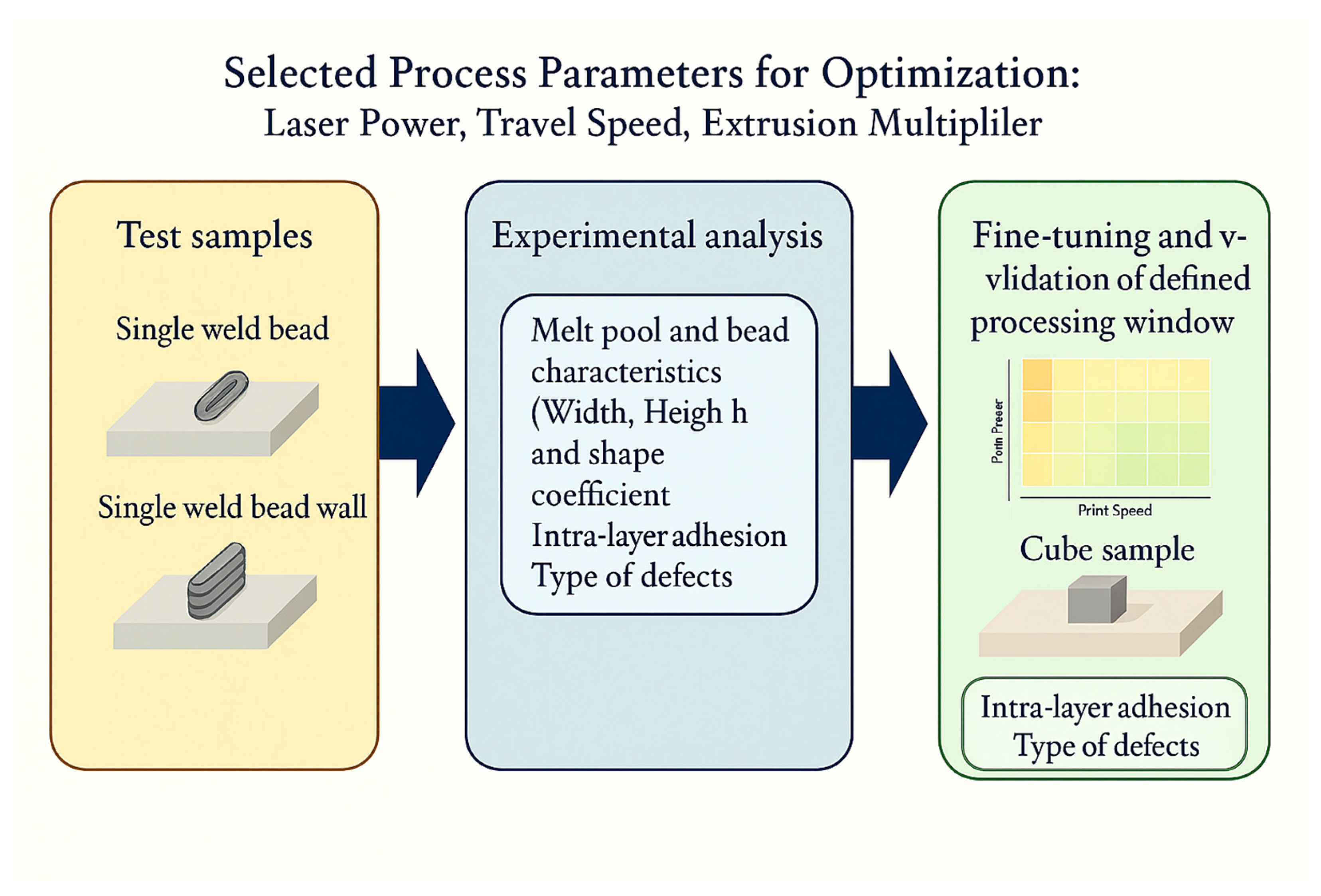
Initially, single-weld beads and single-weld bead walls were produced to narrow down the process parameter window, followed by cubic samples that were fabricated on a 304 stainless steel baseplate. Single-bead walls were fabricated by depositing one continuous single-weld bead per layer, with successive beads stacked vertically to form thin-walled structures. For manufacturing of cubic samples, 1 mm and 1.2 mm weld–bead distances were selected for trials to ensure sufficient overlapping between adjacent weld beads. The substrate was cleaned with an organic solvent to remove impurities. The Taguchi method was applied for the design of experiments (DoE) and the orthogonal array method was used to provide a well-balanced experiment with minimum number of trials. Two DOEs were produced, with a low laser power (300–500 W) and high laser power (600–900 W) respectively. In total, 27 single-weld beads per DOE were produced. The main process parameters (factors) were classified into 3 levels as presented in Table 3 and Table 4. The orthogonal array of Taguchi L9 is shown in Table 5. The three main processing parameters that were varied to fabricate the single scan tracks were laser power (300–900 W), travel speed (300–700 mm/min) and extrusion multiplier (1, 2.5 and 5), which is defined as the ratio between the wire feed rate and travel speed. The overall workflow for parameter optimization is presented in Figure 1.
The application of the Taguchi method in this study was driven by the need to efficiently explore a wide process parameter space under constrained experimental resources, as is often the case in feasibility-driven manufacturing research. The primary objective of the optimization was to identify a robust and stable process window for wire-based directed energy deposition (w-DED) of AISI 420 martensitic stainless steel, with a focus on achieving defect-free bead morphology, consistent melt pool behavior, and adequate substrate fusion. These criteria are critical for ensuring the structural integrity and dimensional reliability of the resulting mold inserts, particularly in emergency manufacturing scenarios where rapid deployment and functional validation take precedence over exhaustive statistical modeling. The selection of laser power, travel speed, and extrusion multiplier as the three main process parameters was informed by their well-established influence on energy input, melt pool dynamics, and deposition quality in laser-based additive manufacturing processes. Laser power directly governs the thermal energy delivered to the substrate, affecting melt pool size, penetration depth, and solidification behavior. Travel speed modulates the interaction time between the heat source and the material, influencing bead geometry and cooling rates. The extrusion multiplier, defined as the ratio of wire feed rate to travel speed, controls the volumetric deposition rate and plays a key role in maintaining a stable material flow and avoiding defects such as stubbing or over-deposition. These parameters have been widely recognized in the literature as primary drivers of deposition quality in DED processes, and their inclusion in the experimental design was essential for establishing a reliable baseline for subsequent mold fabrication [48].
By employing the Taguchi L9 orthogonal array, the study was able to systematically vary these parameters across a representative range while minimizing the number of experimental trials. This approach enabled the identification of an optimal parameter set that consistently produced high-quality single beads and multi-layer structures, forming the foundation for the successful fabrication of functional injection mold inserts. The methodology aligns with the practical constraints and rapid iteration cycles characteristic of emergency manufacturing environments, where time, material availability, and process reliability are critical factors.
Moreover, the laser power range examined for the cubic samples varied between 700 and 1200 W, which is the maximum laser power of the w-DED system, with a 100 W interval, while the speed varied between 300 and 700 mm/min, as presented in Table 6. The test cubes were cut from the 304 stainless steel baseplate with a bandsaw machine.

2.3. Metallographic Preparation

A wire EDM system was used to cut cross-sections of the printed specimens. Metallographic preparation was performed on the cross-sectioned samples prior to the measurement of the height, width, depth and shape coefficient (N) of the deposits on a scanning electron microscope (SEM) (Thermo Fisher Scientific, Phenom ProX, Waltham, MA, USA), as well as the quantitative measurement of the relative density of the cubes via optical microscopy. It is noted that the shape coefficient, N, defined as the depth-to-width ratio of the weld pool, is a parameter identified as a quantitative way to describe an acceptable morphology of the weld pool that will possibly enable us to select the most promising sets of process conditions. This factor should ideally be between 0.35 and 0.5, which indicates that proper welding with the substrate has been achieved [49,50,51]. The 3D-printed cubic samples were cross-sectioned in the transverse direction and mounted in bakelite resin. Next, the samples were grounded using P120, P240, P320, P1200 and P2000 silicon carbide grounding paper, followed by polishing with 3 μm and 1 μm diamond suspensions to achieve a mirror-surface finish. The polished samples were then etched with 10% oxalic acid reagent for at least 2 min under an applied voltage of 2 V.

2.4. Heat Treatment

Heat treatment of the DED-processed AISI 420 components was carried out in three stages. First, a subcritical tempering treatment was applied to facilitate subsequent machining, during which the samples were heated to 500 °C, held for 3 h, and air-cooled to room temperature to reach hardness values < 40 HRC. After machining to final geometry, the parts underwent a heat treatment cycle consisting of austenitization at 1080 °C for 3 h, followed by quenching in water to transform the austenite into martensite. Finally, the hardened specimens were subjected to a tempering treatment at 300 °C for 2 h to achieve the desired final mechanical properties required for injection molding applications.

2.5. Hardness

After the fabrication of trial inserts via the DED process and subsequent heat treatment, hardness measurements were conducted using Leeb apparatus according to ASTM A956 “Standard Test Method for Leeb Hardness Testing of Steel Products” [52], to determine the hardness of the fabricated SS 420. During the hardness tests, measurements were obtained across the whole parts’ surface, keeping a distance of 5 mm between two sequential impact points, since a repeated impact on the same point may affect the test results.

2.6. Post-Process Machining

The annealed inserts were subsequently subjected to machining in order to achieve the desired design features for each mold insert. Machining was initially performed on trial inserts in order to verify that the designed parts’ dimensions were precise for the final post-processing stage, and simultaneously, that the hardness after the annealing process had reached the required values. All optimized printed inserts were subsequently sent to Pascoe Engineering Ltd. (Glasgow, UK) to perform the final post-processing stage, encompassing CNC as well as die-sinking electrical discharge machining (EDM).

2.7. Design for Additive Manufacturing—DfAM

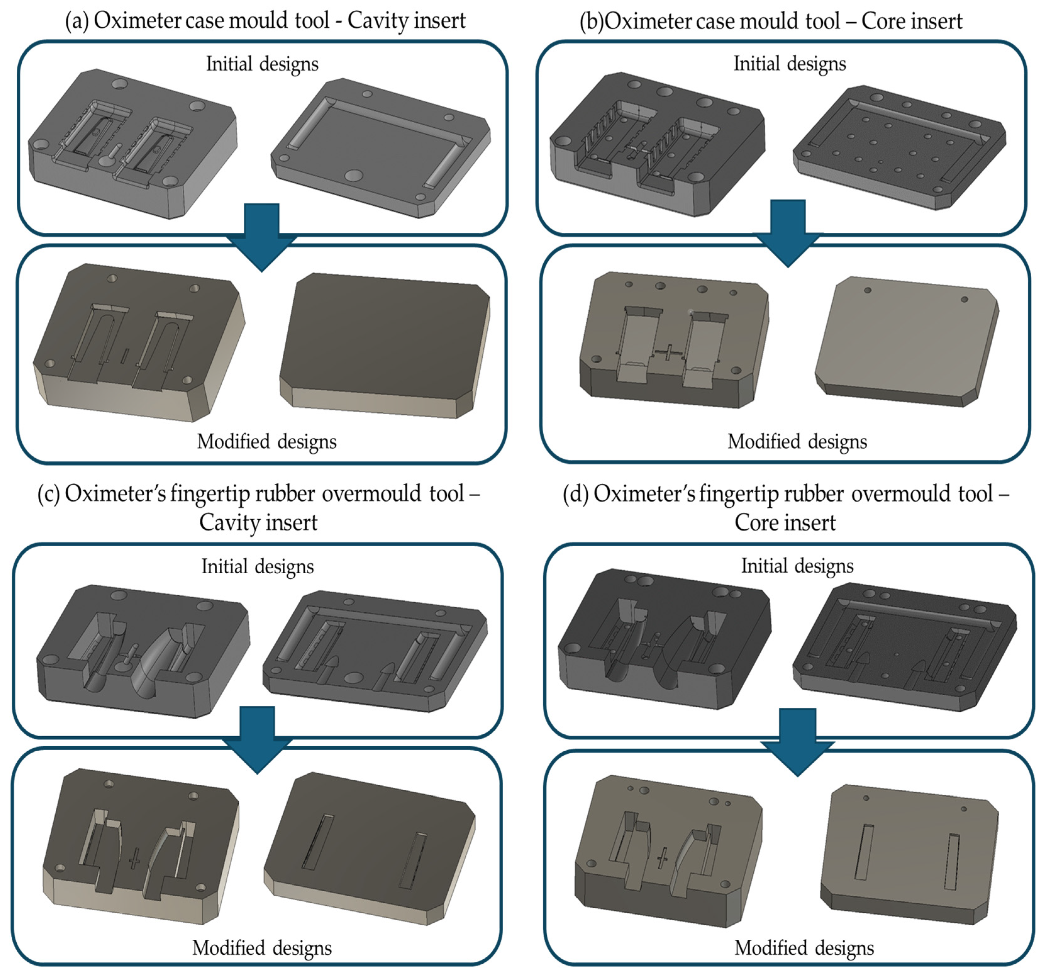
The methodology followed for redesigning all sets of mold inserts based on the available DED machine’s printing capabilities is described in this section. DED is not a suitable means of creating support structures and complex internal features; therefore, it poses certain limitations in terms of geometrical complexity that can be achieved. Features and support structures for overhang surfaces (referred as “Downskin”) are imposed by the printer and its resolution, mainly affected by the diameter size of the used wire. In addition, complex features were removed due to the limited resolution. For the oximeter mold inserts, the material of choice is SS 420 wire of 1 mm diameter, which results in an approximate minimum resolution of 1.6 mm. For this reason, it was necessary to remove features with dimensions smaller than 1.6 mm from the insert designs. Inserts produced through DED are subject to post-processing in order to achieve the required dimensional accuracy and roughness (Ra = 0.025 μm). For this test case, Computer Numerical Control (CNC) machining and die-sinking electrical discharge machining (EDM) are necessary as following steps. Thus, all inserts were redesigned by adding 2 mm of material on all sides and offsetting the cavities’ surface, to ensure enough material clearance for machining and surface finishing. With DED, surface quality and vertical resolution are dependent on the printed layer height. For the oximeter mold inserts, a layer height of 0.8 mm was chosen based on the 1 mm diameter of the metal wire, which was a trade-off in order to maintain a balance between good surface quality and faster printing times. On this basis, every vertical and non-planar feature smaller than the value mentioned above was removed from the insert designs, as presented in Figure 2.

3. Results

3.1. Single-Weld Beads

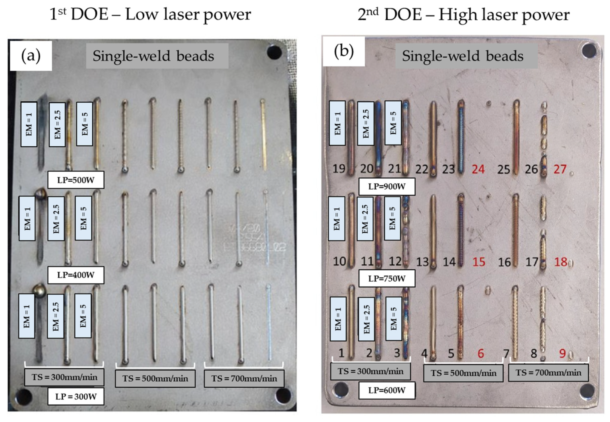
Single-weld beads were deposited to assess the effect of the DED process parameters (laser power, travel speed and extrusion multiplier) of the formed melt pool and resultant beads’ geometrical characteristics (height, width, and depth). More specifically, twenty-seven SS 420 single tracks were built for each DOE, as shown in Figure 3, with all possible combinations of process parameters for optimization. The parameters selected for all single beads are presented in Table 3 and Table 4.
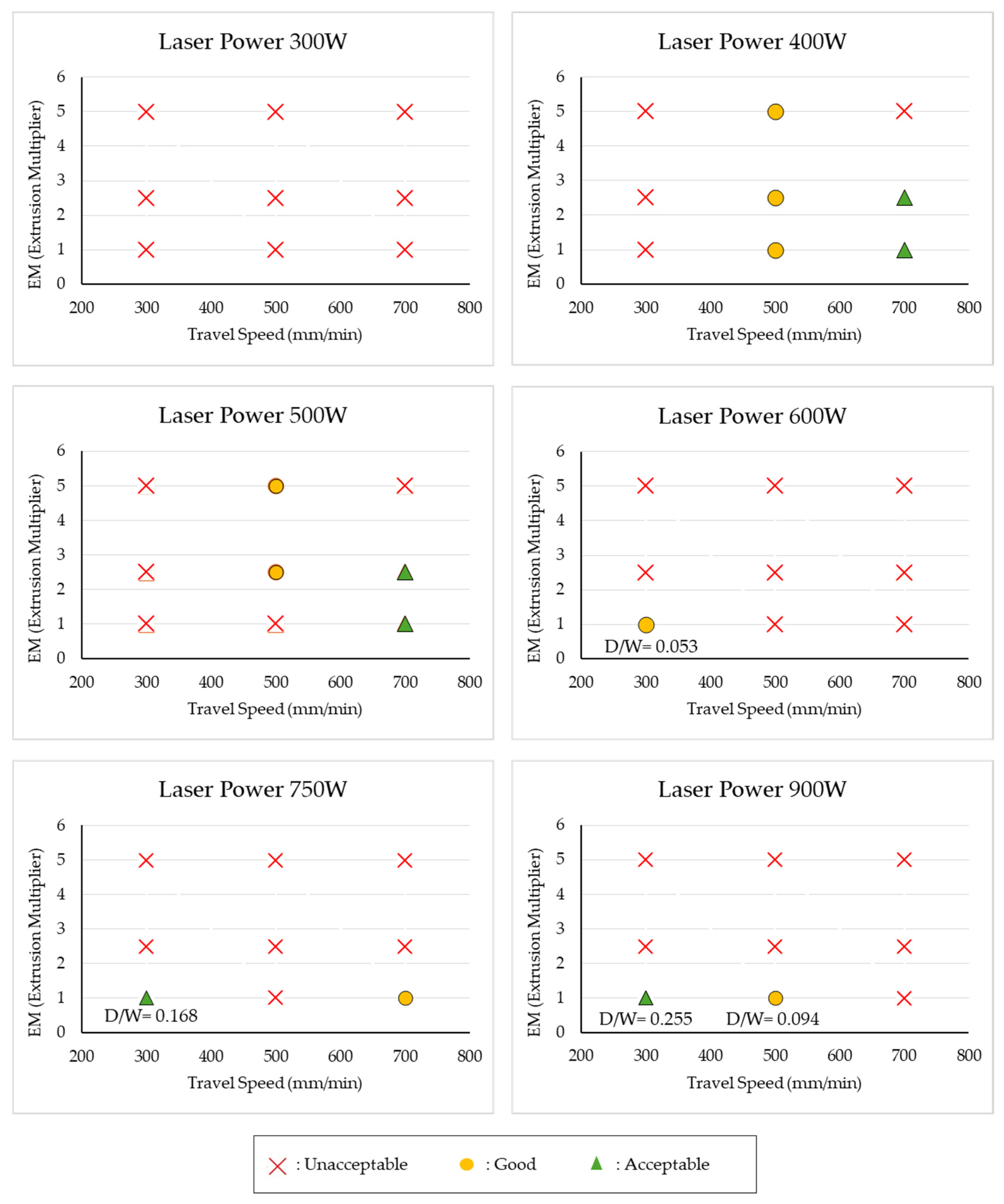
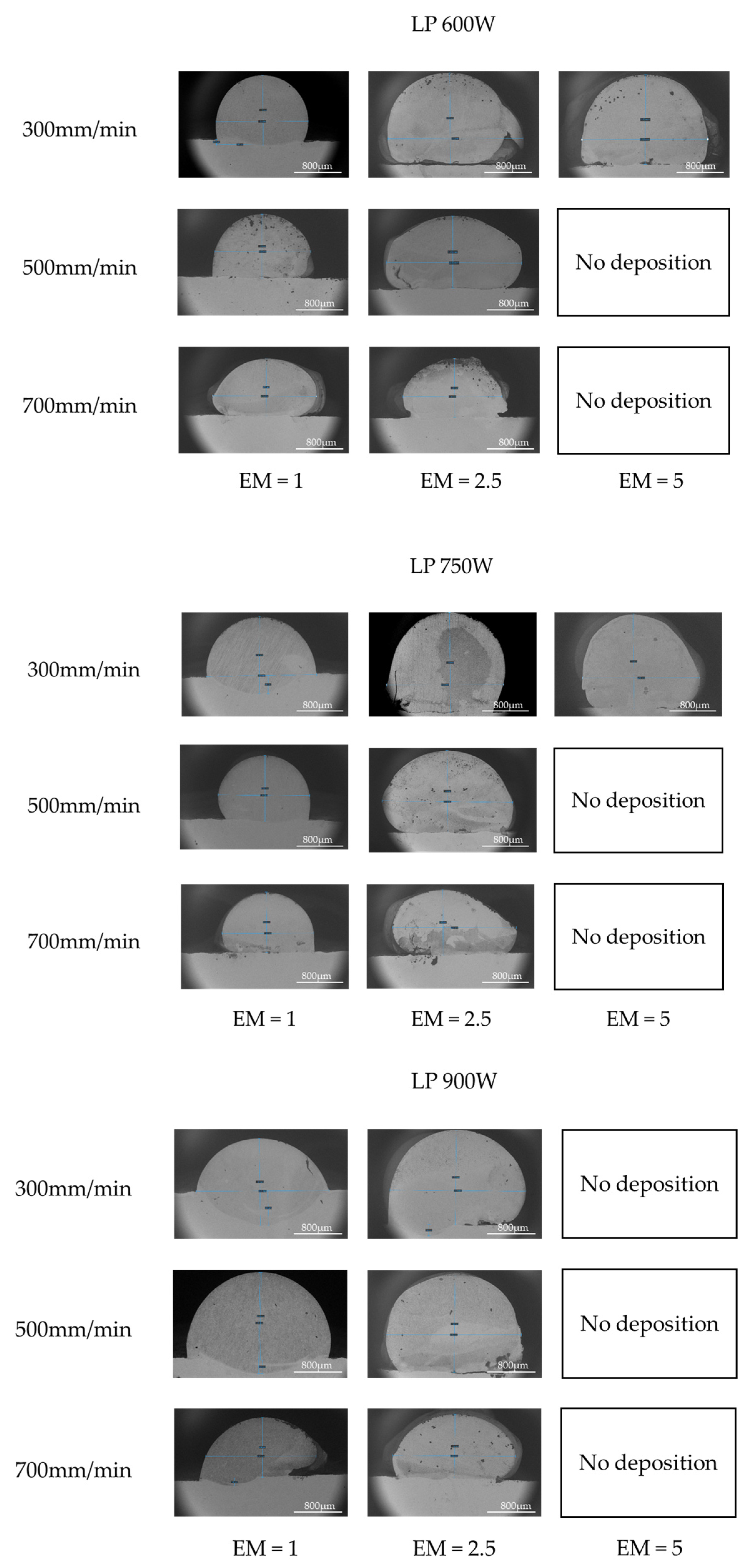
Following deposition, all single-weld beads were subjected to visual and metallurgical inspection (i.e., melt pool depth, width, height, wetting angle) to assess bead integrity and melt pool penetration. For DoE 1, which employed the lowest combinations of energy input (laser power, travel speed, and extrusion multiplier), no effective penetration into the substrate was observed. The resulting beads exhibited insufficient fusion and inconsistent geometrical formation, making them unsuitable for quantitative evaluation. Therefore, only the single tracks produced in DoE 2, where adequate energy input enabled stable melt pool formation and full-bead penetration, were selected for further characterization and assessment. SEM micrographs of single beads produced for the DoE 2 with high laser power are presented in Figure 4. The processing regime was evaluated based on the quality of the single beads produced. The process parameter sets were assessed based on the single beads and their wetting angle with the substrate, the penetration to the substrate, and the overall defect-free deposition. It is evident that with increased extrusion multiplier (EM = 5), the majority of single beads are not successfully deposited on the substrate, irrespectively of laser power and travel speed combination.
A qualitative analysis that summarizes the process window for SS 420 across a wide range of process parameters is presented in Figure 5, including results from both DOEs conducted for single-bead experiments. The quality of the beads is classified as unacceptable when the single bead is not deposited, as good when the single bead is deposited on the substrate and as acceptable when the single bead is defect-free and penetrates the substrate (adhesion). The process window for both DOEs and all combinations of process parameters is presented in Figure 5.

3.2. Multi-Bead Sample Fabrication Within a Fast-Track Mold Making Methodology

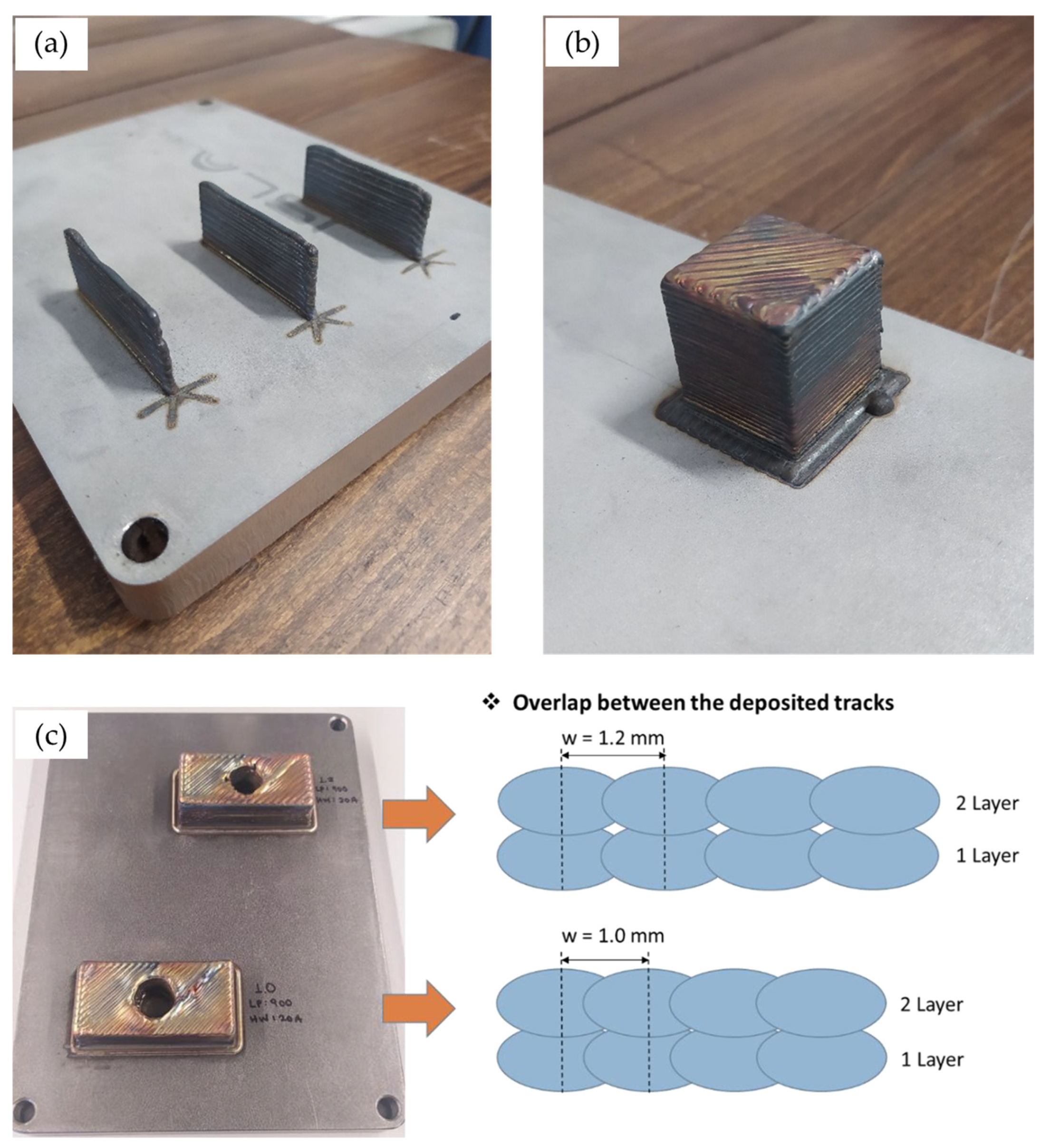
To streamline and accelerate the mold making process using laser wire directed energy deposition (DED), the transition from single-bead experiments to multi-bead sample fabrication is a critical step in establishing a robust methodology. Following the initial assessment of process parameters via single-weld beads, multi-bead samples were systematically produced in the forms of thin walls (single-bead multi-layer builds, Figure 6a), cubic (Figure 6b), and block specimens with holes (Figure 6c). This iterative approach enabled rapid optimization of wire extrusion width, lateral and vertical bead overlap, and identification of key defects such as underfill, excessive overlap, sidewall waviness, lack of fusion between passes, and progressive distortion.
By producing thin-wall structures, the methodology ensured precise control over the extrusion width and single-bead stacking, allowing for the evaluation and adjustment of lateral and vertical build integrity. The cubic and block samples served as testbeds for assessing thermal effects, including heat accumulation and remelting, which can lead to coarse grain formation or porosity when multiple passes are performed sequentially. Such systematic evaluation facilitated the selection of optimal parameter sets to minimize defects and ensure dimensional accuracy.
Within this fast-track workflow, laser power and travel speed were fine-tuned in conjunction with the wire extrusion width, which was set at 1.0 mm and 1.2 mm for cubic sample production. This enabled rapid convergence on process conditions that promote stable deposition, consistent microstructure, and reliable fusion between layers. The methodology thus integrates iterative experimental feedback, process parameter refinement, and defect analysis, forming a unified framework for efficient, high-quality mold insert fabrication by additive manufacturing.

3.3. Microstructure

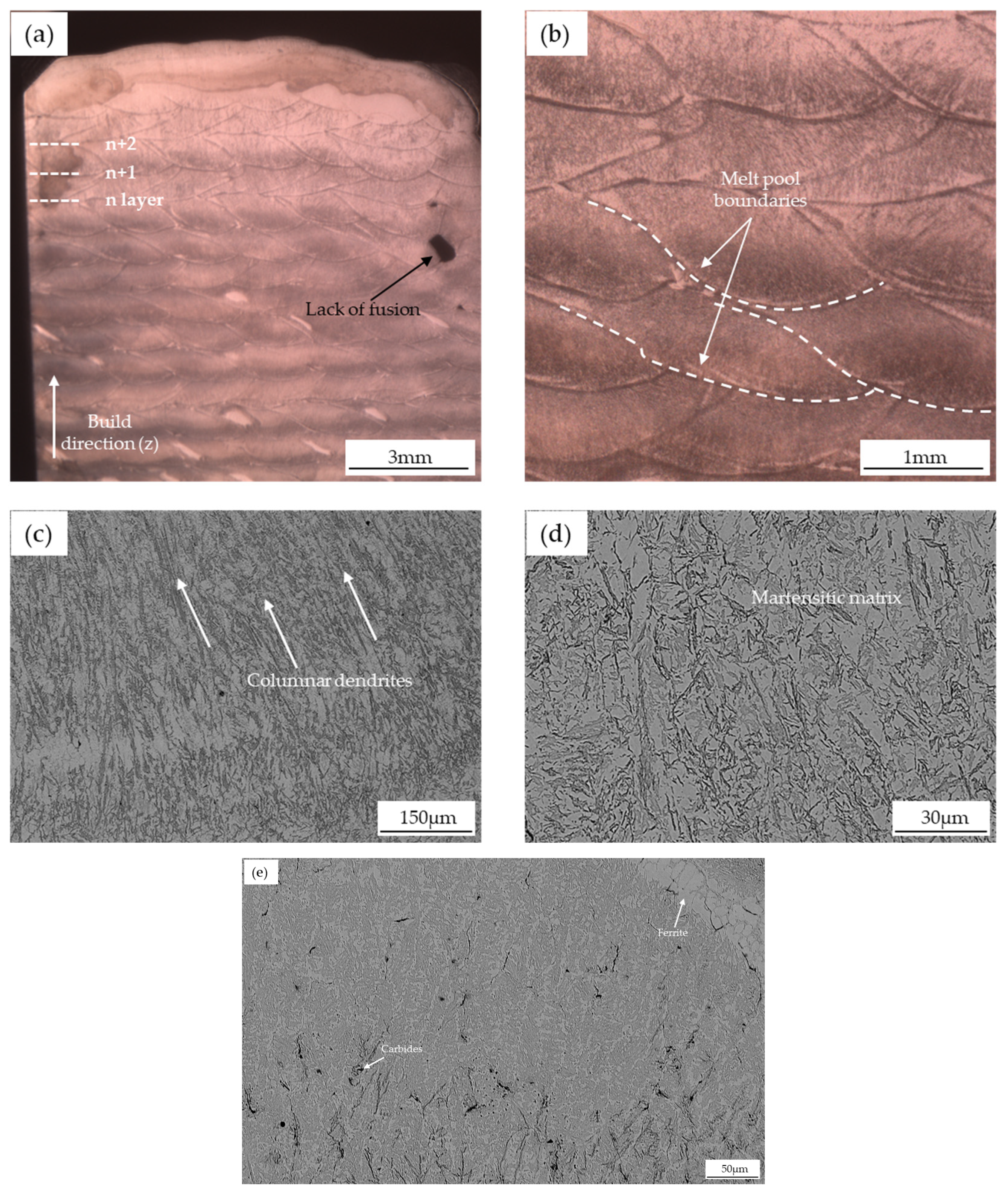
Figure 7 provides a detailed visual representation of the microstructural characteristics observed in the cubic samples fabricated via laser wire directed energy deposition (DED) using SS 420 stainless steel. In Figure 7a, the complete cubic sample is depicted, highlighting the sequential layer deposition along the build (z) direction, which is fundamental to the additive manufacturing process. Notably, an isolated lack-of-fusion defect is identified by a black arrow, illustrating one of the potential challenges associated with improper process parameter selection or insufficient interlayer bonding. This defect underscores the importance of optimizing deposition conditions to ensure consistent fusion between layers and minimize porosity or mechanical weaknesses. Figure 7b focuses on the as-consolidated cross-sectioned SS 420 material, revealing the presence of fine cellular dendrites that form due to rapid solidification during the DED process. These dendritic structures are oriented transverse to the build direction, reflecting the directional solidification patterns imposed by the layer-by-layer manufacturing approach. Furthermore, Figure 7c,d offer two orthogonally cross-sectional views of the same dendritic microstructure, emphasizing the anisotropic and hierarchical nature of the resulting microstructure. The images collectively illustrate that each deposited layer consists of two distinct sub-layers: a primary sub-layer dominated by directionally solidified dendrites and a thinner secondary sub-layer composed of fine equiaxed grains. The martensite is characterized by fine, interlocking laths and packets that exhibit the typical needle-like morphology expected from the rapid self-quenching conditions inherent to laser-based directed energy deposition. Such lath/plate martensitic structures are consistent with those reported for laser-DED and laser-cladded AISI 420, where high cooling rates drive the formation of α′-martensite with a refined substructure.
In the upper-right portion of the micrograph in Figure 7e, a distinct, light-gray, polygonal region is visible, lacking any acicular substructure. This area is attributed to δ- or α-ferrite, a phase known to occur in DED-processed 420 stainless steel due to solidification-mode transitions and local chromium enrichment. The presence of such ferritic islands has been previously reported in WAAM- and DED-fabricated 420, where δ-ferrite persists along melt pool boundaries or regions exposed to repeated reheating.
This layered, composite microstructure is a direct consequence of the repeated thermal cycling and rapid cooling inherent to the DED technique, which leads to unique distributions of martensite, retained austenite, and finely dispersed carbides throughout the build. Overall, the microstructure consists of a martensitic matrix containing scattered carbides and isolated ferritic regions, matching the heterogeneous solidification and thermal cycle history typical of laser-DED AISI 420 stainless steel. Such microstructural features are critical in determining the mechanical properties, including hardness and toughness, of the final component, and demonstrate the significance of microstructural analysis in evaluating and optimizing additive manufacturing processes for high-performance tooling applications.

3.4. Prototypes

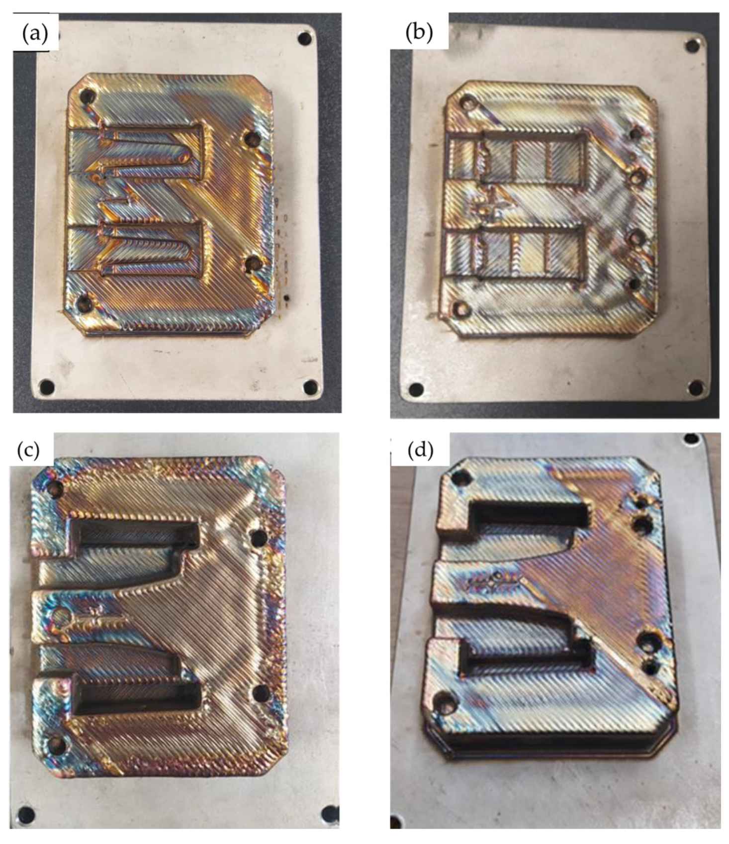
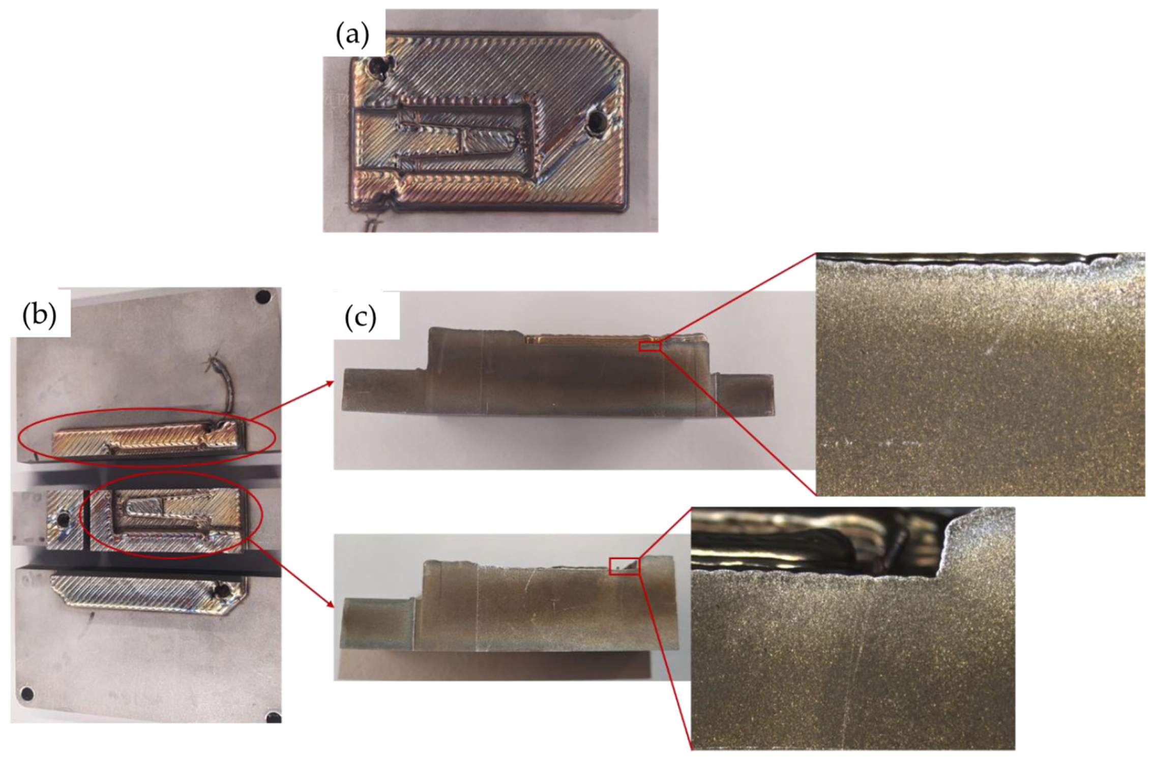
The cavity insert molds were sectioned into halves using CAD software (FreeCAD 1.0.2) and printed as prototypes to validate the optimum process parameter set and assess any type of defects, as shown in Figure 8. The process parameters selected for the fabrication of all oximeter modular mold inserts, based on conducted trial experiments, are as follows: print speed set to 700 mm/min and laser power set to 900 W; extrusion multiplier factor, extrusion width and height of the wire were set to 1, 1.0 mm and 0.8 mm, respectively. The inert gas flow was adjusted to 6 L/min, while the AISI 420 stainless steel (SS) wire of 1 mm diameter was preheated through a supply of 20 A current and 5 V voltage. Moreover, the inserts were printed on 304 SS build plates, while a rectilinear (±45°) printing strategy was selected for the material’s deposition through the DED machine. The inserts were cross-sectioned to further examine porosity and cracks. Due to the insert’s high geometrical complexity in specific areas (e.g., spikes and internal cooling channels), the 3D printer’s tolerances in terms of printability could not meet the design’s dimensional accuracy. Based on these observations, the provided designs for the oximeter’s cavity insert were suitably modified by considering the machine’s limitations and accuracy, as well as necessary post-AM processing, namely CNC/EDM and finishing, to be used for the next printing experiments.
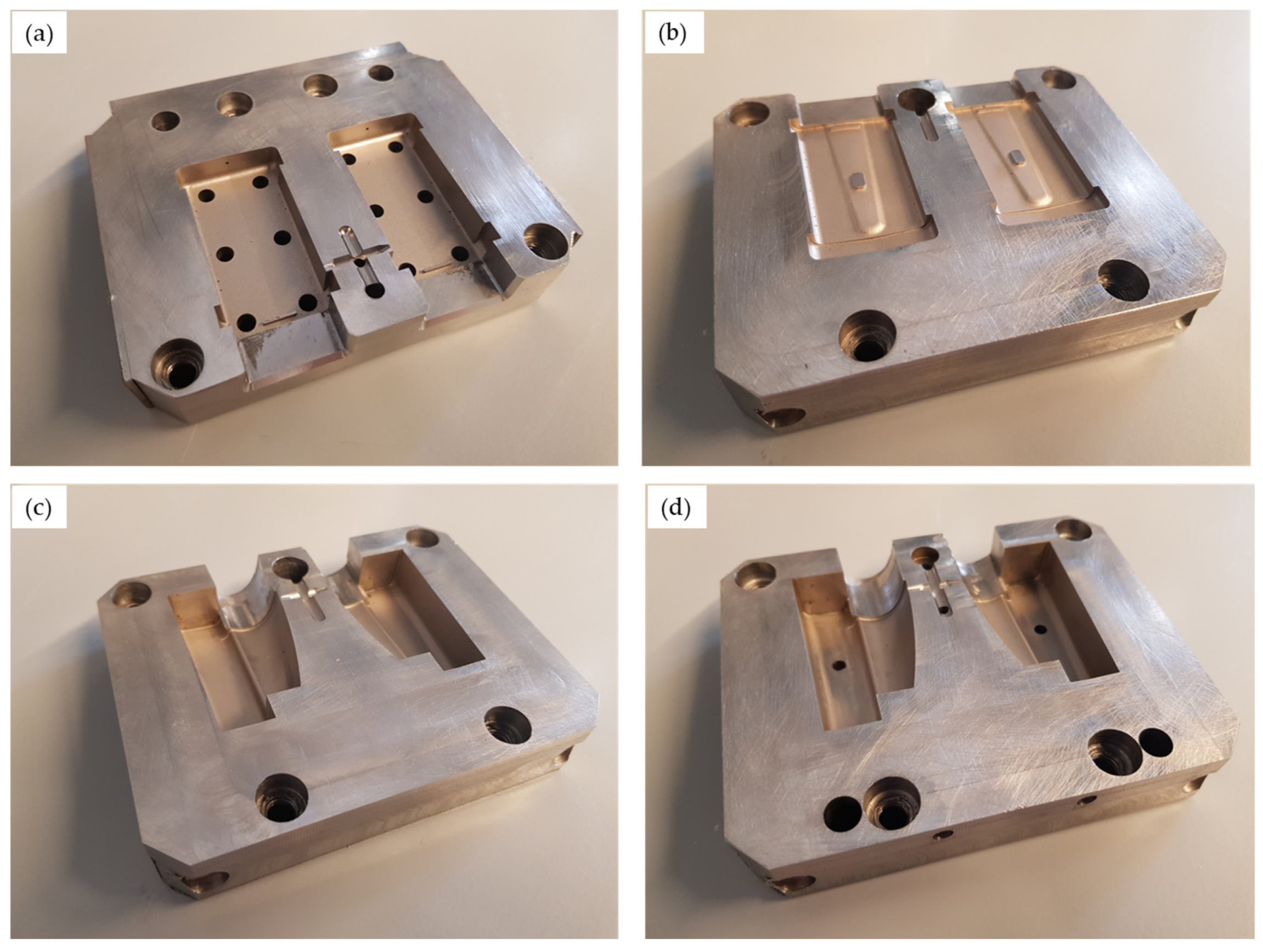
Once the prototypes were assessed, the full inserts for the oximeter’s case and the oximeter’s fingertip rubber overmold tool were produced and are presented in Figure 9. After the AM process and subcritical tempering, machining of the AM inserts was conducted by Pascoe Engineering Ltd., following the same workflow as for conventionally manufactured inserts. The process comprised the following steps: squaring the insert blocks to the required external dimensions, machining the inserts to fit the master tool, rough milling of the cavities, drilling of the cooling channels, and finish shaping of the cavities by die-sinking EDM without subsequent polishing. Subsequently, and prior to IM trials, the blocks were subjected to annealing heat treatment steps and tempering towards a high-performance injection molding tooling comprising a uniform, fully hardened and tempered martensitic structure. The additively manufactured blocks were first machined to the final envelope dimensions to ensure proper seating in the mother tool, after which the cavities were rough-cut on a CNC milling center to near-net shape.
Copper electrodes were then used for EDM die sinking to generate the final cavity geometry and surface quality, employing a finisher electrode with a fine setting for the last pass. Cooling channels were produced in the same manner as for the conventional inserts, by drilling longitudinally and transversely through the inserts and sealing the cross-drilled holes with plugs. Following these operations, the DED-fabricated core and cavity inserts met the same dimensional and functional requirements as their conventionally machined counterparts. Electrical discharge machining (EDM) of copper is a nontraditional machining process used to generate complex, precise mold features in hardened tool steels and other difficult-to-cut materials [53,54]. In EDM, a shaped copper electrode (tool) and a conductive workpiece are submerged in a dielectric fluid, and a series of controlled electrical discharges occurs across a small gap between them. Each discharge forms a high-temperature plasma channel that locally melts and partially vaporizes material on both the electrode and the workpiece surface. When the pulse ends, the plasma collapses and the dielectric flushes away the molten debris, leaving a small crater. By repeatedly pulsing and moving the electrode along a programmed path, the negative of the electrode geometry is reproduced in the mold cavity [55]. Copper is frequently used for EDM electrodes because of its high electrical and thermal conductivity, good machinability, and relatively low cost compared with graphite or tungsten–copper [56]. These properties allow efficient energy transfer, good flushing of the gap, and reasonable tool wear, especially in finishing operations where fine detail and low surface roughness are required. Copper electrodes can be produced by conventional subtractive machining (milling, turning, grinding), additive manufacturing routes [57], or a combination, and then used in die-sinking EDM to form deep cavities, sharp corners, microfeatures, or thin ribs that would be difficult or impossible to machine mechanically. Following these operations, the DED-fabricated core and cavity inserts met the same dimensional and functional requirements as their conventionally machined counterparts.
The average hardness measured across the part’s surface was approximately 57 HRC in the as-built condition. The as-printed cavity inserts were subsequently machined and heat-treated at 1080 °C for 3 h in a protective atmosphere (austenitizing step) to comply with a roughness value of Ra = 0.025 μm and a hardness of 32 HRC after austenitization, as required by the injection molding line owner (PASCOE). The machined and heat-treated mold are depicted in Figure 10. The measured final surface hardness of 28.26 HRC was achieved after an additional tempering step at 300 °C for 2 h in a protective atmosphere, and it was acceptable by PASCOE.

3.5. Cost Calculation

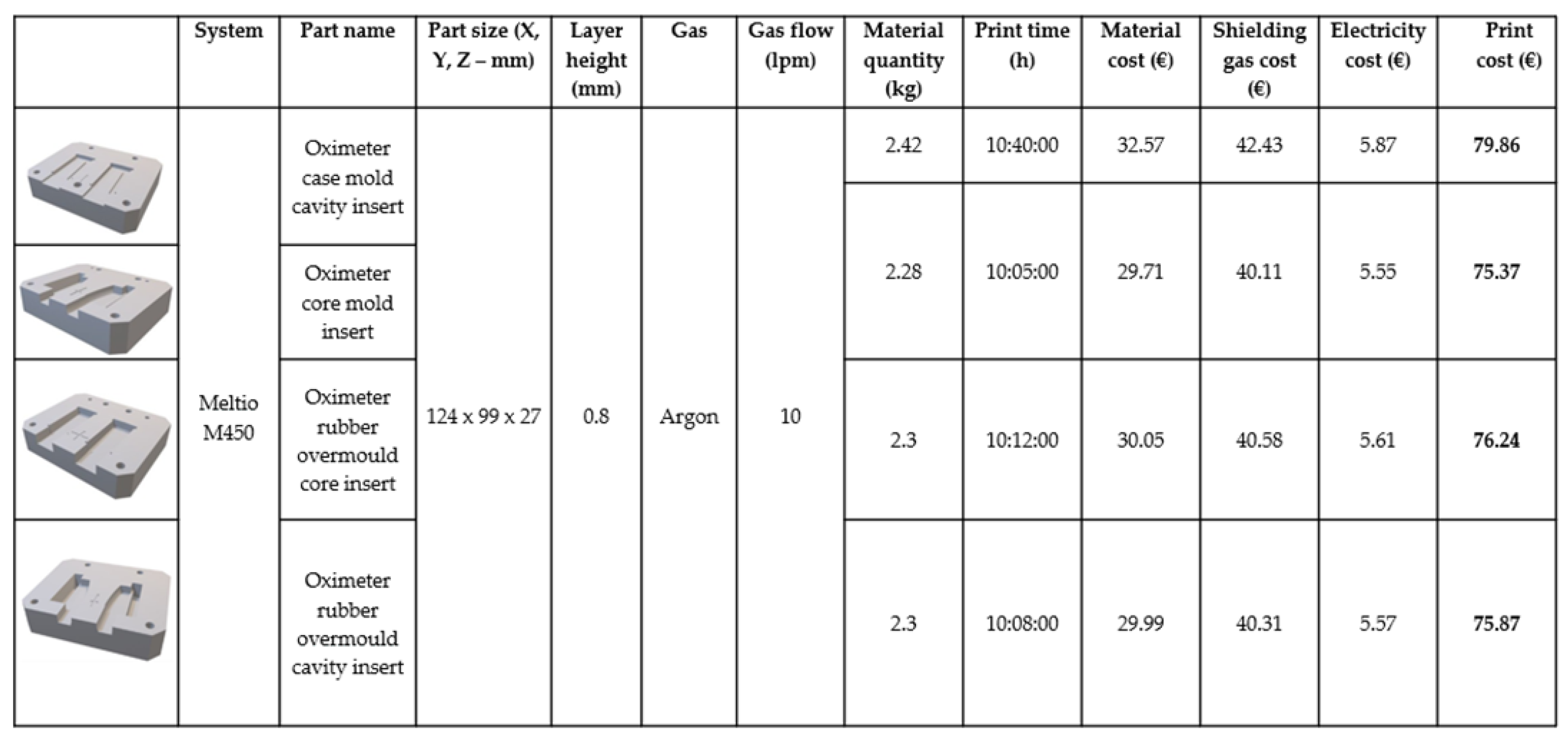
Metal molds produced by wire-DED show competitive direct manufacturing costs that are largely governed by material consumption, shielding gas, electricity, and machine time. In Figure 11, the representative costs for three mold inserts are shown; the print cost is on the order of 75–80 € per part, with material cost as the dominant contributor, followed by shielding gas and then electricity. Machining and heat treatment expenses are not included in the scope of this study. The four inserts have similar envelope dimensions and weights, leading to comparable print times (about 10–10.5 h) and only modest variations in consumable usage; this indicates that, once a parameter window is established, wire-DED delivers relatively predictable and repeatable build costs across functionally similar mold designs. For design-for-AM variants such as the rubber overmold core, the cost structure remains similar, suggesting that geometric modifications to improve functionality (e.g., integrated features or conformal cooling) do not necessarily incur a strong penalty in consumable-based printing cost, provided the overall volume and height remain comparable. When compared with conventional mold making, these direct AM costs must be interpreted alongside tooling and process economics from the literature. Traditional subtractive routes (CNC milling, drilling, EDM) typically incur higher upfront costs in programming and fixturing, as well as longer lead times, especially for complex cores or cavities with deep features and multiple setups. Several lifecycle and decision-support studies show that DED-based manufacture and repair become economically attractive for high-value tools where material removal from solid blocks would generate substantial waste or require extensive machining time. In particular, Morrow et al. [58] report that for simple, massive molds with a high solid-to-cavity volume ratio, CNC milling remains more economical and environmentally favorable, whereas for geometrically complex inserts with a low solid-to-cavity volume ratio, DED offers advantages in both material efficiency and cost, due to reduced buy-to-fly ratio and shorter process chains.
From a repair and lifecycle perspective, wire-DED further improves the cost picture by enabling local refurbishment of worn regions rather than full replacement. Studies on DED repair operations show that repair can significantly cut material usage, embodied energy, and lead time, especially when only a fraction of the mold surface is damaged. In such cases, repair costs are dominated by short build times and limited added material, while the remaining tool body is reused; decision-support models demonstrate that for many high-value inserts, this leads to favorable break-even points compared with manufacturing a new tool, even when the hourly machine rate of DED equipment is relatively high. Overall, the cost data from the attached examples, combined with the literature, support the view that wire-DED is particularly cost-effective for complex or customized mold inserts, for design-for-AM geometries, and for repair scenarios—while conventional machining continues to be more economical for simple, highly solid mold blocks with limited geometric complexity.

3.6. Injection Mold Production

The production of the oximeter includes injection molding of the oximeter case, the lid, the window tool and overmolding of rubber. The design of modular mold inserts and mold sets follows the idea of material stock minimization, fast changeover and flexibility in production. The modular parts must share a main mold structure, injection system, hot or cold running system, cooling system, in-and-out circulation system, tightening and guiding system, etc. Also, the system has to be easy to assemble. For manufacturing the molds, the mold inserts consist of cavity inserts and core inserts and they can be fitted into a master mold. The hybrid ceramic modular mold inserts for the oximeter casing internal cavity are produced via an additive manufacturing process. In addition, the inserts are machined to fit the mother tool before sparking erodes the cavities with the new electrodes. The internal cooling channel is necessary for overmolding of the core insert. With the mold sets for manufacturing the oximeter case, the lid, the glass holder and the overmolding of rubber, the production trial can be conducted to test the production rate and the quality of the parts. Initial production trials at Pascoe Engineering Ltd. used a modified injection molding line, and the new mold sets completed 1000 cycles without defects. Based on the trials, the oximeter case was produced at a rate of 260 parts/h, while the lid and glass holder production achieved a rate of 171 parts/hour. For the overmolding process, 260 rubber parts can be overmolded to the case per hour. This test served as a reliability and reproducibility assessment of the optimized process parameters (900 W laser power, 700 mm/min travel speed, and extrusion multiplier of 1) applied to the manufacturing of multiple mold inserts with varying geometries, all manufactured under consistent conditions. All inserts were successfully produced without defects and subsequently employed in injection molding trials, where they consistently performed as intended. This outcome demonstrates the robustness of the selected process window and its applicability across different mold designs. While a formal statistical analysis of process variability was beyond the scope of this feasibility-focused study, the consistent performance across multiple builds and geometries provides practical evidence of process stability.

4. Discussion

4.1. Single Beads

The single-bead experiments establish the process window for stable w-DED of SS 420 and provide the baseline for subsequent multi-layer builds. At low extrusion multipliers (EM ≈ 5), continuous tracks could not be produced reliably, independent of laser power and travel speed, indicating that the material feed rate was insufficient to sustain a stable melt pool. Under these conditions, lack of fusion, intermittent bead formation, and sporadic stubbing of the wire were frequently observed, evidencing incomplete melting and consolidation of the incoming wire. As the energy input was increased (higher laser power and/or lower travel speed) at larger EM values, the tracks evolved into geometrically stable beads with consistent width and height, confirming that robust track formation requires a balanced combination of energy density and material supply.
The cross-sectional analyses show that bead geometry—width, height, penetration depth—and the associated shape coefficient (width/height) vary systematically with process parameters. Higher laser power or reduced travel speed produced wider, deeper beads due to the larger melt pool and higher linear energy input, whereas-sectional analyses show that bead geometry—width, height, penetration depth—and the associated shape coefficient (width/height) vary systematically with process parameters. Higher laser power or reduced travel speed produced wider, deeper beads due to the larger melt pool and higher linear energy input, whereas higher travel speeds or reduced power resulted in narrower and shallower tracks with increased surface waviness. Excessive heat input led to wire dripping and overwide beads, compromising dimensional control, while insufficient input caused stubbing and porosity. Mapping the shape coefficient as a function of travel speed and EM revealed a narrow process window where beads are fully consolidated yet not excessively overbuilt. These results underline that stable single-track formation in SS 420 w-DED is highly dependent on coordinated adjustment of EM, laser power, and travel speed, and that this first level of optimization is critical for achieving dimensionally accurate, defect-free walls and bulk features in subsequent builds. Single-bead trials conducted at 750 W/300 mm s−1 and 900 W/300 mm s−1 were used to establish a stable processing window for martensitic SS420. The 900 W condition consistently generated a fully developed melt pool with continuous flow, improved wetting behavior, and uniform bead geometry, whereas the lower-energy condition showed an increased tendency toward lack-of-fusion defects and geometric variability—behavior characteristic of 12–14% Cr martensitic stainless steels, where linear energy input strongly governs penetration depth, bead morphology, and the extent of carbide dissolution near the fusion boundary.

4.2. Processing and Microstructure

Building on the findings from single beads, the fabrication of 3D solid structures was performed at 900 W with a print speed of 700 mm min−1 (extrusion multiplier = 1.0; extrusion width = 1.0 mm; wire height = 0.8 mm). The adoption of a higher traverse speed was enabled by the significantly enhanced thermal dissipation present in multi-track, multi-layer builds, where the larger effective heat sink and improved heat conduction pathways promote a more stable melt pool regime. This thermal environment suppresses overheating, reduces melt pool lifetime fluctuations, and prevents defect formation mechanisms such as balling, porosity accumulation, or hot cracking. Additionally, martensitic SS 420 is particularly sensitive to thermal cycling near the martensite start temperature (Ms). Effective thermal management during high-power deposition mitigates solidification segregation and reduces microstructural heterogeneity that would otherwise increase cracking susceptibility [59]. These combined effects justify the feasibility of operating at increased print speeds under the 900 W condition, ensuring stable deposition while maintaining bead quality and structural integrity.
The microstructure of 420 stainless steel fabricated via laser wire directed energy deposition (DED) is defined by a complex, layered hierarchy resulting from rapid melting and solidification coupled with intense thermal cycling. The primary solidification structure is characterized by fine cellular or columnar dendritic grains, which grow epitaxially from the substrate or previous layer, creating a strong <100> crystallographic texture aligned with the build direction. Within this framework, the final as-deposited phase is predominantly lath martensite, formed as the high-temperature delta ferrite and subsequent austenite transform during rapid cooling [60]. This martensitic matrix is highly dislocated and typically retains between 5 and 15% austenite, which persists as thin films along the lath boundaries. A critical feature of this additive process is the inherent thermal cycling, where successive deposition layers reheat those beneath. This creates distinct microstructural zones throughout the build. The uppermost, freshly deposited material consists of untempered lath martensite. In contrast, the underlying material undergoes in situ tempering from the heat of subsequent layers, transforming into tempered martensite. Here, recovery processes reduce dislocation density, and chromium-rich M23C6 carbides precipitate and coarsen, often spheroidizing within the matrix and along lath boundaries. This results in a periodic hardness variation, with softer, tempered regions alternating with harder, as-deposited zones.
Furthermore, the rapid solidification kinetics promote a relatively uniform distribution of fine carbides and limit the gross segregation seen in conventional casting, although micro-segregation of chromium and carbon persists in interdendritic regions. The process also yields a minimal heat-affected zone compared to arc-based methods, leading to a sharp transition at the substrate interface. Consequently, the final microstructure is not homogeneous but an engineered, anisotropic laminate of untempered and tempered martensite, fine retained austenite, and a dispersion of carbides, all locked within a directionally solidified grain structure that confers unique mechanical properties distinct from its wrought or cast counterparts. The chemically etched as-consolidated SS 420 material exhibits a layer-wise directionally solidified fine dendritic microstructure along the build direction, reflecting the nature of layer-upon-layer deposition during the laser consolidation process. It can be seen in Figure 6 that each layer actually includes two sub-layers: one sub-layer with predominated directionally solidified dendritic structure and another thin sub-layer of fine equiaxed grains. During laser wire DED, the bead zone’s top and bottom regions as well as the heat-affected zone (HAZ) undergo varying cooling rates and experience differential volumetric changes within their crystal structures. The rapid solidification process proceeds from delta ferrite to austenite, followed by transformation from austenite to martensite. A minor fraction of delta ferrite is believed to segregate, whereas the majority transforms into austenite. Additionally, it is probable that some austenite remains untransformed, retained in the microstructure after martensite formation. The volume fraction of delta ferrite present in interdendritic areas and the retained austenite dispersed in the matrix are minimal relative to the predominant martensitic matrix volume. This disparity likely contributes to residual stresses at the microscale, arising from differences in lattice structure among the body-centered cubic delta ferrite, face-centered cubic austenite, and body-centered tetragonal martensite phases. Furthermore, the precipitation of metallic carbides and sulphides, alongside eutectic delta ferrite, may influence volume changes within these crystallographic planes. The substrate’s HAZ also plays a critical role, as its cyclic thermal distortions during successive heating and cooling cycles induce tensile stresses. Comparable findings were reported by Chen et al. in their study of P20 tool steel [61].
The combination of higher traverse velocity and lower laser power results in lower incident energy at the top of the part, typically resulting in finer microstructures due to higher cooling rates. In contrast, lower cooling rates and coarser microstructures can be produced by decreasing traverse speed and increasing laser power [57,62,63,64,65]. Although material type undoubtedly influences grain morphologies of laser w-DED parts, lower laser beam or lower incident energy, which can be due to laser attenuation and/or radiation effects, tends to result in finer equiaxed structures, while higher laser power and higher incident energy generally result in columnar grains and coarser microstructures [64,65].
Several studies [6,8,9,10,11] have reported microstructural characterizations for laser-cladded iron-based materials. Wu et al. [6] studied the laser-consolidated AISI 420 stainless steel (420SS) and observed a fine dendritic microstructure in a directionally solidified nature with duplex austenite (A) and martensite (M) phases. They also reported 53.9 vol.% of retained austenite in their findings, which remained even after post-heat treatment at 1008 °C for 30 min, followed by tempering at 477 °C. In other studies, Alam et al. [39], Brnic et al. [43], and Chen et al. [47] reported the presence of eutectic delta ferrite as the second phase along with martensite and traces of retained austenite in the laser cladding/welding of SS 420. Marsden et al. [66] measured dendritic cell spacings produced by laser melting SS 420 material and found that, with an order of 3~4 μm, the estimated cooling rate was about 103 °C/s from the liquid state. Thus, it is understood that the high cooling rate associated with the laser consolidation process results in the high nucleation rate along with the rapid growth of dendrites with very small space between primary arms. As a result, laser-consolidated SS 420 exhibits very fine cellular dendrites with preferred growth along the build direction. Colaco and Villar [67,68] theoretically analyzed the primary solidification mode in the competition between the δ and γ phases and concluded that primary δ solidification mode is kinetically favored at higher solidification speeds, whereas primary δ solidification mode predominates at very low solidification speeds. Therefore, as-consolidated SS 420 material presents a resultant microstructure of austenite dendrites partially transformed into martensite.
Distinct microstructure regions with fairly different microhardness values have been reported for DED AISIH13 tool steel [69,70,71], AISI 420 tool steel [72], AISI 4140 steel [73], AISI 410 stainless steel (SS) [74], AISI P20 tool steel [75], AISI 316L stainless steel [75,76], Inconel 625 [45,77,78], and Ti-6Al-4V components [79]. It has been reported that for steels, the microhardness values of subsequent deposited layers decrease from the first deposited layer and then increases toward the top layers [37,74,80]. This inhomogeneity can be attributed to the time-variable cooling rate of the melt pool and a relatively slower velocity of solidification in the middle region. The middle region is also exposed to cyclic reheating (related to subsequent layer deposition) and experiences a substantial heat-affected zone (HAZ) for a longer period of time. As a result, higher microhardness has generally been measured at the top and bottom of DED parts, which undergo higher cooling rates during the DED process as compared to the middle region [80,81]. Chen et al. [47,82] observed low yield strength and tensile strength in the laser-consolidated AISI 420 stainless steel (SS420) compared to their wrought counterparts of commercial grade. However, they found higher mechanical properties in the heat-treated sample of the same at 1008 °C for 0.5 h with tempering at 316 °C for 2 h.

4.3. Heat Treatment and Impact on Microhardness

Applying heat treatment after directed energy deposition (DED) confers multiple benefits to the machinability of SS 420 stainless steel. Primarily, it alleviates internal stresses present in the as-deposited material, which helps prevent deformation or distortion during later machining stages. This is crucial for preserving dimensional accuracy and achieving consistent, high-quality finishing results. The process also results in a more uniform microstructure by dissolving localized carbides and minimizing compositional variations within the alloy. Such evenness is vital for steady and predictable material removal rates during both CNC milling and electrical discharge machining (EDM), allowing for smoother surface finishes and reliable mold insert performance. Following the laser wire directed energy deposition (DED) process, SS 420 stainless steel typically exhibits a predominantly martensitic microstructure, conferring substantial hardness but leaving the material susceptible to residual stresses, microcracking, and chemical inhomogeneity. Without proper heat treatment, these features can significantly compromise the functional reliability and longevity of mold inserts employed in demanding industrial environments.
The microstructural evolution observed in the present work reflects the characteristic thermal history of AISI 420 processed by laser-based directed energy deposition. As reported in recent laser-DED studies, the as-built material solidifies predominantly into a martensitic matrix containing retained austenite and δ-ferrite, accompanied by strong microstructural heterogeneity arising from repeated reheating during layer-wise deposition. These findings align with the plate and lath martensite morphologies, nano-carbide precipitation, and residual stress distributions documented in laser-cladded AISI 420, where rapid solidification and steep thermal gradients govern phase selection and martensitic transformation. The initial subcritical tempering step applied in this work serves to homogenize the extent of auto tempering created during DED, reducing residual stresses while limiting carbide coarsening—a behavior consistent with low-temperature tempering studies on laser-cladded 420, where martensite decomposes into finer tempered martensite with Fe3C and M23C6 precipitation [81,83].
Subsequent austenitizing at 1080 °C is required to fully dissolve these carbides and restore a homogeneous austenitic structure prior to quenching, a process that is well established in heat treatment investigations on 420 stainless steel, which show that austenitizing above the Ac3 temperature eliminates ferrite–carbide aggregates and resets the microstructure for martensitic re-transformation. In contrast, high-temperature exposure followed by slow cooling for extended dwell times has been shown in recent L-DED studies on AISI 420S to promote recrystallization, grain coarsening, and the formation of a ferrite–carbide aggregate, resulting in very low hardness and loss of martensitic features, as also demonstrated in the present work. The final tempering treatment at 300 °C is therefore essential to stabilize the freshly formed martensite, producing a tempered martensitic matrix with a fine dispersion of carbides, as well as a microstructure known to deliver the hardness, wear resistance, and dimensional stability required for tooling and mold applications. This necessity is reinforced by WAAM studies of AISI 420, where as-built martensitic structures exhibit brittleness and require appropriate post-heat treatment to achieve functional performance [84,85].
The balance between hardness and ductility is critical for mold inserts, which must withstand repeated mechanical and thermal cycling in service. The selection of tempering parameters is application-specific, as these adjustments directly influence wear resistance, resistance to impact, and tolerance to repeated thermal loads—all pivotal properties for injection molding and die-casting molds. Nguyen et al. [86] performed a comparative analysis of different heat treatment schedules and concluded that the combination of low-temperature tempering with cryogenic treatment post-solutionizing yielded the best results in terms of the trade-off between hardness and ductility, with up to 30% improvement in elongation at break compared to conventional protocols. Selecting the appropriate tempering parameters is key to achieving the right balance between hardness and toughness, making SS 420 more accommodating to machining while still providing the strength required for its intended application. This approach prevents the inserts from becoming too brittle or too soft, ensuring both ease of machining and durability over time. Improved machinability directly impacts the quality of the finished surface and supports the achievement of precise tolerances—an essential factor for mold inserts, where even slight deviations can affect part functionality and service life. Additionally, enhanced machinability extends the lifespan of cutting tools and improves overall cost-effectiveness, as less tool wear and lower cutting forces contribute to reduced post-processing expenses. In summary, implementing a carefully designed heat treatment protocol following DED not only strengthens the mechanical characteristics of SS 420 but also simplifies downstream machining, enabling the production of mold inserts that meet the rigorous standards required for modern injection molding and die-casting operations. Incorporating an optimized post-DED heat treatment regime is required for realizing the full benefits of additive manufacturing in tooling. This multi-stage treatment not only mitigates the metallurgical heterogeneity introduced by DED processing but is also vital for achieving the mechanical and dimensional integrity expected of modern mold steels.

4.4. DfAM Strategies for Enhancing Printability of Complex Features in W-DED

Design for Additive Manufacturing (DfAM) provides the foundational framework necessary to address the inherent challenges of wire-based directed energy deposition (w-DED), particularly when fabricating complex or intricate features. While w-DED is distinguished by its capacity to produce near-fully dense metallic components, its relatively coarse resolution—compared to powder-based processes like Laser Powder Bed Fusion (LPBF)—imposes fundamental constraints on the geometric complexity and precision of as-built parts. These limitations manifest in the difficulty of producing fine details, internal channels, and sharply defined features, as well as the process’s sensitivity to surface irregularities, which can introduce defects such as roughness, wire jamming, or misalignment. As a result, a robust DfAM approach must be adopted to unlock the process’s full potential and ensure manufacturable, high-quality components.
The theoretical principles of DfAM for w-DED begin with the recognition that the process’s achievable resolution and the physical interaction between the wire and the substrate dictate the feasible range of geometries. Effective strategies emphasize designing components with smooth transitions, rounded contours, and uniform wall thicknesses, avoiding abrupt changes, sharp corners, or slender sections that are prone to incomplete formation or structural weakness. For elements that exceed the process’s capability—such as intricate internal channels or ultra-fine features—a hybrid manufacturing route is recommended, wherein the bulk structure is additively manufactured and critical details are subsequently introduced through subtractive processes like CNC machining or EDM. Additionally, modularization—dividing the part into discrete subcomponents for later assembly—can circumvent feature-size limitations and facilitate reliable fabrication. Optimizing build orientation is another core tenet of DfAM, as it enables designers to minimize unsupported overhangs and maintain unobstructed access for the wire feed and heat source, thereby mitigating the risk of defects and improving surface quality. The employment of advanced simulation tools further augments this approach by predicting thermal distortion, bead morphology, and potential failure points, allowing for iterative refinements prior to fabrication. Material selection and process parameter optimization are also integral to DfAM, as the choice of alloy and careful tuning of parameters like wire feed rate, travel speed, and heat input directly influence bead consistency and the fidelity of complex geometries. Allowances for post-processing are embedded into the initial design, ensuring that additional material is provided on critical surfaces for subsequent finishing operations to achieve precise tolerances and surface finishes.
These DfAM principles were systematically applied and validated in the case study involving the fabrication of modular oximeter mold inserts, based on designs provided by Pascoe Engineering Ltd. The transition from conventional die design to w-DED required a comprehensive redesign methodology, tailored to the process’s unique capabilities and constraints. For example, the typical inclusion of internal cooling channels with circular cross-sections—standard in traditionally machined dies—was reconsidered, as w-DED cannot reliably produce unsupported internal features or generate removable support structures during deposition. Instead, the redesigned inserts omitted such channels from the additive build, incorporating them through post-build drilling to ensure manufacturability and structural integrity. The adaptation to the process’s minimum feature size was another critical modification. Given the use of 1 mm diameter SS 420 wire, the minimum printable feature was established at approximately 1.6 mm. Consequently, all design details below this threshold were eliminated to prevent print failures and ensure dimensional fidelity. Anticipating the necessity for post-processing, a uniform 2 mm material offset was added to all insert surfaces, including cavity regions, to accommodate CNC machining and die-sinking EDM. This provision ensures the final geometry and surface quality meet stringent industrial requirements, with surface roughness (Ra) targets as low as 0.025 μm. Furthermore, the geometric configuration of features in relation to the layer-wise deposition process was carefully controlled. The selected layer height of 0.8 mm dictated that vertical or non-planar features smaller than this dimension were either removed or reconfigured, thereby avoiding the creation of surfaces that could not be consistently or accurately produced. This step was essential to minimizing surface irregularities and optimizing production efficiency without sacrificing functional performance.
Through the deliberate integration of these DfAM-driven adaptations—removal of non-manufacturable features, strict adherence to process-imposed resolution limits, built-in allowances for post-processing, and geometric refinement relative to deposition parameters—the resulting oximeter mold inserts exemplify a unified, application-specific approach to w-DED. This methodology not only ensures that the inserts are manufacturable within the constraints of w-DED, but also that they achieve the dimensional accuracy, surface finish, and functional robustness necessary for high-performance industrial molding applications. The case study thus demonstrates the critical importance of harmonizing theoretical DfAM principles with practical design modifications to fully realize the benefits of additive manufacturing for complex precision components.

4.5. Cost and Sustainability

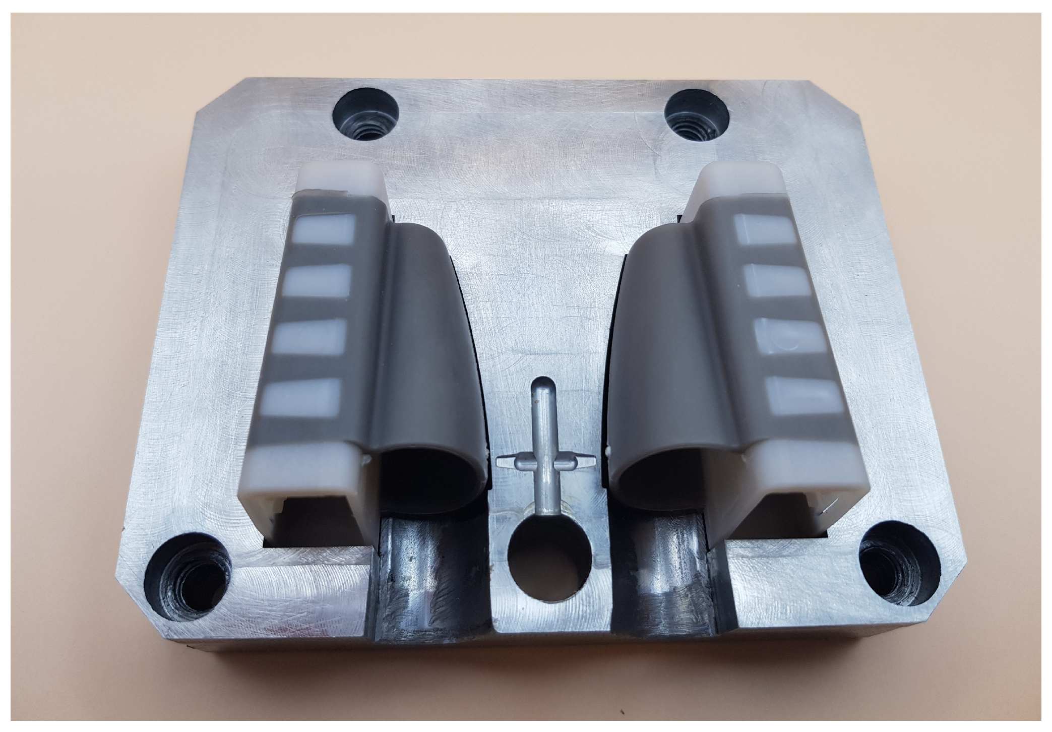
The cost analysis of the oximeter case study shows that w-DED can be economically competitive with conventional CNC machining for mold inserts when designs are adapted to the process and build parameters are well optimized (Figure 12 showing the operational condition of w-DED mold with injected oximeter). In the examined scenarios, direct printing costs for individual inserts are dominated by material consumption and shielding gas, with electricity and machine time constituting smaller, yet non-negligible, contributions. The three investigated mold configurations exhibit similar build times and cost structures, indicating that once a parameter set is established, w-DED offers predictable, repeatable costs across design variants of comparable volume. This stability is particularly attractive when implementing DfAM-driven design changes, as it allows functional improvements (for example, modularization or geometry simplification for printability) without disproportionate increases in production cost.
From a broader sustainability perspective, w-DED aligns with the trends identified in recent lifecycle and decision-support studies on DED tooling, which highlight the interplay between energy use, material efficiency, and economic performance. For simple, highly solid mold blocks, conventional subtractive machining from wrought plate may remain preferable due to high material removal rates and relatively short machining times. However, for more complex inserts with lower solid-to-cavity volume ratios, or in repair scenarios where only a fraction of the tool needs refurbishment, w-DED can significantly reduce both material waste and lead time. In such cases, the break-even point often favors DED, particularly when downtime costs and environmental metrics such as embodied energy and CO2 emissions are taken into account. Within this context, the present cost study reinforces the view that w-DED is a viable and, in many cases, advantageous route for manufacturing and repairing high-value mold inserts, provided that the process is coupled to rigorous DfAM and post-processing strategies.

5. Conclusions

This study examined the feasibility of manufacturing a set of SS420 injection molds via w-DED, used for the production of oximeters, and the following conclusions can be drawn from this research:
  • Low laser power of the single-laser weld beams resulted in discontinuities and insufficient penetration to the substrate, irrespectively of the travel speed employed. The optimum process parameter set was defined for LP 900 W, a travel speed of mm/min and extrusion multiplier of 1.
  • Insufficient heat input yielded fabrication defects such as wire stubbing, whilst excessive heat input contributed to defects such as wire dripping. Test cubes fabricated at optimal heat input were of good quality without any defects.
  • The microstructure of the test cubes generally comprised ferrite dendrites on the austenite matrix, regardless of the laser power and travel speed; however, the lower laser power resulted in lack of fusion in between the sequential layers.
  • As-printed SS420 material shows a refined dendritic microstructure, indicating that the material experienced fast cooling during re-solidification. The resultant as-consolidated SS420 microstructure consisted of a majority of retained austenite along with transformed martensite.
  • The hardness of SS420 was measured in the as-built condition as 57HRC, while it was reduced in the heat-treated condition, featuring a hardness value of 32HRC after austenitization. The hardness of the molds was further reduced after tempering reaching a value of 28HRC.
  • The findings demonstrate that metal w-DED delivers significant advantages in tooling agility, cost-efficiency, and sustainability, particularly when responding to unpredictable spikes in demand. Furthermore, the study highlights how localized and distributed AM facilities could be rapidly mobilized to address global supply chain disruptions. Insights are provided into process parameter optimization, challenges associated with wire-based deposition, and the broader implications for integrating additive technologies in fast-response manufacturing environments.
  • Research on cost optimization for the post-processing operations (post-heat-treatment CNC machining and EDM) of metal injection molds is currently lacking in the literature, suggesting that there might be room for additional cost savings. It is of relevance to evaluate the total costs, such as the supply chain costs, and quantify the cost of metal AM in a decentralized supply chain configuration to fully understand the cost competitiveness. Future work should consider the extension of the cost model to include different metal AM machines and materials (wire arc, wire-DED, powder DED, etc.). Additional elementary data will contribute to the improvement of the accuracy of the cost analysis. The inclusion of additional machines and data will help to broaden the scope of the cost model and provide more comprehensive insights into the economic implications of AM in medical supplies. Future studies could also investigate the potential cost advantages and disadvantages of different metal AM systems and processes and their respective cost structures.
Despite its advantages in deposition rate and material efficiency, w-DED presents inherent limitations for tooling applications. The relatively coarse resolution of the process restricts its suitability for fabricating fine features or intricate geometries, such as conformal cooling channels commonly required in high-performance injection molds [87]. Additionally, the as-built surface finish and dimensional accuracy of w-DED parts typically necessitate extensive post-processing, including machining and polishing, to meet the stringent tolerances and surface quality standards of mold tooling [88]. These constraints limit the applicability of w-DED in high-precision or micro-scale tooling. However, in emergency manufacturing scenarios—such as the COVID-19 pandemic response addressed in this study—w-DED offers a compelling combination of speed, robustness, and material efficiency. Its ability to rapidly produce functional mold inserts using readily available wire feedstock makes it particularly well suited for time-critical, resource-constrained environments where conventional manufacturing routes may be disrupted, while rapid deployment and functional adequacy are prioritized.

Author Contributions

Conceptualization, L.G., E.P.K. and E.K.K.; methodology, L.G., E.K.K. and E.P.K.; formal analysis, L.G., E.K.K. and E.P.K.; investigation, L.G., E.P.K. and E.K.K.; writing—original draft preparation, L.G. and E.K.K.; writing—review and editing L.G., E.K.K. and E.P.K.; supervision, E.P.K. and E.K.K.; project administration, L.G. and E.K.K.; funding acquisition, E.P.K. and E.K.K. All authors have read and agreed to the published version of the manuscript.

Funding

This research was funded by the European Commission under Horizon-H2020-SC1-PHE-CORONAVIRUS-2020-2 and Grant Agreement Project 101016262—imPURE (Injection Molding Repurposing for Medical Supplies enabled by Additive Manufacturing). The views and opinions expressed are, however, those of the authors only and do not necessarily reflect those of the European Union.

Data Availability Statement

The data presented in this study are available on request from the corresponding authors. The data are not publicly available due to privacy restrictions.

Acknowledgments

The authors would like to thank Stavros Deligiannis, Chara Kousiatza and Nikolaos Barbakos for their technical support and Pascoe Engineering Ltd. for their collaboration throughout the imPURE project.

Conflicts of Interest

The authors declare no conflict of interest.

Abbreviations

The following abbreviations are used in this manuscript:
AM Additive Manufacturing
DED Directed Energy Deposition
DLD Direct Laser Deposition
WAAM Wire Arc Additive Manufacturing
WA-DED Wire Arc Directed Energy Deposition
DOE Design of Experiments
IM Injection Molding
CNC Computer Numerical Controlled
EDM Electrical Discharge Machining
CAD Computer-aided Design
CMSs Critical Medical Supplies
w-DED Wire-based Directed Energy Deposition
DfAM Design for AM
STL Stereolithography
SS Stainless Steel
PAMHT Post-Additive Manufacturing Heat Treatments
MSSMartensitic Stainless Steel
FSSFerritic Stainless Steel
ASSAustenitic Stainless Steel
DSSDuplex (austenite and ferrite) Stainless Steel
PHSSPrecipitation Hardenable Stainless Steel

References

  1. Heaney, D.F. Handbook of Metal Injection Molding, 2nd ed.; Woodhead Publishing: Cambridge, UK, 2019. [Google Scholar] [CrossRef]
  2. Teshome, F.; Asmare Tsegaw, A. Metal Injection Molding (MIM) Process and Potential Remedies for Its Defects: A Review. In Proceedings of the Advances of Science and Technology, Bahir Dar, Ethiopia, 27–29 August 2022; pp. 309–325. [Google Scholar] [CrossRef]
  3. Tuteski, O.; Kocov, A. Mold Design and Production Using Additive Manufacturing (Am)—Present Status and Future Perspectives. Int. Sci. J. Ind. 4.0 2018, 3, 82–85. [Google Scholar]
  4. Becerra-Borges, Y.E.; Cazon-Martin, A.; Rodriguez-ferradas, M.I.; Morer-camo, P.; Etxaniz-Sein, U.; Manchado, J.C.; Candal, M.V. Transforming plastic injection molding with additive manufacturing: A novel systematic review of innovative approaches to insert production. Rapid Prototyp. J. 2025, 31, 200–218. [Google Scholar] [CrossRef]
  5. Milutinović, M.; Movrin, D.; Pjević, M.; Popović, M. Additive Manufacturing: A Key to Advancing Injection Molding Efficiency. Teh. Glas. 2025, 6168, 141–146. [Google Scholar]
  6. Wu, T. A Framework for Optimizing the Design of Injection Molds with Conformal Cooling for Additive Manufacturing. Procedia Manuf. 2015, 1, 404–415. [Google Scholar] [CrossRef]
  7. Saifullah, A.B.M.; Masood, S.H.; Nikzad, M. An Investigation on Fabrication of Conformal Cooling Channel with Direct Metal Deposition for Injection Moulding; Elsevier Ltd.: Amsterdam, The Netherlands, 2016. [Google Scholar] [CrossRef]
  8. Kanbur, B.B.; Suping, S.; Duan, F. Design and optimization of conformal cooling channels for injection molding: A review. Int. J. Adv. Manuf. Technol. 2020, 106, 3253–3271. [Google Scholar] [CrossRef]
  9. Shinde, M.S.; Ashtankar, K.M.; Kuthe, A.M.; Dahake, S.W. Direct rapid manufacturing of molds with conformal cooling channels. Rapid Prototyp. J. 2018, 24, 1347–1364. [Google Scholar] [CrossRef]
  10. Moshiri, M.; Loaldi, D.; Zanini, F.; Sgaravato, D.; Carmignato, S.; Tosello, G. Analysis of an as-built metal additively manufactured tool cavity insert performance and advantages for plastic injection moulding. J. Manuf. Process. 2021, 61, 369–382. [Google Scholar] [CrossRef]
  11. Fayazfar, H.; Salarian, M.; Rogalsky, A.; Sarker, D.; Russo, P.; Paserin, V.; Toyserkani, E. A critical review of powder-based additive manufacturing of ferrous alloys: Process parameters, microstructure and mechanical properties. Mater. Des. 2018, 144, 98–128. [Google Scholar] [CrossRef]
  12. Pedroso, A.F.V.; Sebbe, N.P.V.; Silva, F.J.G.; Campilho, R.D.S.G.; Sales-Contini, R.C.M.; Costa, R.D.F.S.; Barbosa, M.L.S.; Nogueira, F.R. A Concise Review on Materials for Injection Moulds and Their Conventional and Non-Conventional Machining Processes. Machines 2024, 12, 255. [Google Scholar] [CrossRef]
  13. Mazur, M.; Leary, M.; McMillan, M.; Elambasseril, J.; Brandt, M. SLM Additive Manufacture of H13 Steel with Conformal Cooling and Lattice structures Nomenclature. Rapid Prototyp. J. 2016, 22, 504–518. [Google Scholar]
  14. Impure Project. Available online: https://www.impure-project.eu/ (accessed on 21 January 2026).
  15. Pragana, J.P.M.; Sampaio, R.F.V.; Bragança, I.M.F.; Silva, C.M.A.; Martins, P.A.F. Hybrid metal additive manufacturing: A state–of–the-art review. Adv. Ind. Manuf. Eng. 2021, 2, 100032. [Google Scholar] [CrossRef]
  16. Popov, V.V.; Fleisher, A. Hybrid additive manufacturing of steels and alloys. Manuf. Rev. 2020, 7, 6. [Google Scholar] [CrossRef]
  17. Dardaei Joghan, H.; Hölker-Jäger, R.; Komodromos, A.; Tekkaya, A.E. Hybrid Additive Manufacturing of Forming Tools. Automot. Innov. 2023, 6, 311–323. [Google Scholar] [CrossRef]
  18. Nyamuchiwa, K.; Palad, R.; Panlican, J.; Tian, Y.; Aranas, C. Recent Progress in Hybrid Additive Manufacturing of Metallic Materials. Appl. Sci. 2023, 13, 8383. [Google Scholar] [CrossRef]
  19. Campatelli, G.; Montevecchi, F.; Venturini, G.; Ingarao, G.; Priarone, P.C. Integrated WAAM-Subtractive Versus Pure Subtractive Manufacturing Approaches: An Energy Efficiency Comparison. Int. J. Precis. Eng. Manuf. Technol. 2020, 7, 1–11. [Google Scholar] [CrossRef]
  20. Dias, M.; Pragana, J.P.M.; Ferreira, B.; Ribeiro, I.; Silva, C.M.A. Economic and Environmental Potential of Wire-Arc Additive Manufacturing. Sustainability 2022, 14, 5197. [Google Scholar] [CrossRef]
  21. Merklein, M.; Junker, D.; Schaub, A.; Neubauer, F. Hybrid Additive Manufacturing Technologies—An Analysis Regarding Potentials and Applications. Phys. Procedia 2016, 83, 549–559. [Google Scholar] [CrossRef]
  22. Rabalo, M.A.; Rubio, E.M.; Agustina, B.; Camacho, A.M. Hybrid additive and subtractive manufacturing: Evolution of the concept and last trends in research and industry. Procedia CIRP 2023, 118, 741–746. [Google Scholar] [CrossRef]
  23. Yadollahi, A.; Shamsaei, N. Additive manufacturing of fatigue resistant materials: Challenges and opportunities. Int. J. Fatigue 2017, 98, 14–31. [Google Scholar] [CrossRef]
  24. Singh, G.; Missiaen, J.M.; Bouvard, D.; Chaix, J.M. Additive manufacturing of 17–4 PH steel using metal injection molding feedstock: Analysis of 3D extrusion printing, debinding and sintering. Addit. Manuf. 2021, 47, 102287. [Google Scholar] [CrossRef]
  25. Baghdadchi, A.; Hosseini, V.A.; Valiente Bermejo, M.A.; Axelsson, B.; Harati, E.; Högström, M.; Karlsson, L. Wire laser metal deposition of 22% Cr duplex stainless steel: As-deposited and heat-treated microstructure and mechanical properties. J. Mater. Sci. 2022, 57, 9556–9575. [Google Scholar] [CrossRef]
  26. Ahn, D.-G. Directed Energy Deposition (DED) Process: State of the Art. Int. J. Precis. Eng. Manuf. Technol. 2021, 8, 703–742. [Google Scholar] [CrossRef]
  27. Ahn, D.G. Direct metal additive manufacturing processes and their sustainable applications for green technology: A review. Int. J. Precis. Eng. Manuf.-Green Technol. 2016, 3, 381–395. [Google Scholar] [CrossRef]
  28. Zapata, A.; Bernauer, C.; Stadter, C.; Kolb, C.G.; Zaeh, M.F. Investigation on the Cause-Effect Relationships between the Process Parameters and the Resulting Geometric Properties for Wire-Based Coaxial Laser Metal Deposition. Metals 2022, 12, 455. [Google Scholar] [CrossRef]
  29. Bozeman, S.C.; Isgor, O.B.; Tucker, J.D. Area-based composition predictions of materials fabricated using simultaneous wire-powder-directed energy deposition. Addit. Manuf. Lett. 2024, 11, 100254. [Google Scholar] [CrossRef]
  30. Saboori, A.; Bosio, F.; Librera, E.; de Chirico, M.; Biamino, S.; Lombardi, M.; Fino, P. Accelerated process parameter optimization for directed energy deposition of 316L stainless steel. In Proceedings of the Euro PM2018 Congress & Exhibition, Bilbao, Spain, 14–18 October 2018. [Google Scholar]
  31. Melia, M.A.; Nguyen, H.D.A.; Rodelas, J.M.; Schindelholz, E.J. Corrosion properties of 304L stainless steel made by directed energy deposition additive manufacturing. Corros. Sci. 2019, 152, 20–30. [Google Scholar] [CrossRef]
  32. Yin, Y.; Tan, Q.; Bermingham, M.; Mo, N.; Zhang, J.; Zhang, M.-X. Laser additive manufacturing of steels. Int. Mater. Rev. 2022, 67, 487–573. [Google Scholar] [CrossRef]
  33. Sey, E.; Farhat, Z.N.; Nasiri, A. A Comparative Study of the Tensile Behavior of Wrought 44W Steel, Monel 400, 304L Stainless Steel, and Arc-Directed Energy Deposited 308L Stainless Steel in Simulated Hydrogen Environments. Corros. Mater. Degrad. 2025, 6, 28. [Google Scholar] [CrossRef]
  34. Thangamani, G.; Anand, P.I.; Sahu, A.; Singh, I.; Gianchandani, P.K.; Tamang, S.K. Enhance the microstructure and mechanical properties of directed energy deposition-Arc (DED-Arc) stainless steel 308L using laser shock peening process. Prog. Addit. Manuf. 2025, 10, 8537–8555. [Google Scholar] [CrossRef]
  35. Svetlizky, D.; Zheng, B.; Vyatskikh, A.; Das, M.; Bose, S.; Bandyopadhyay, A.; Schoenung, J.M.; Lavernia, E.J.; Eliaz, N. Laser-based directed energy deposition (DED-LB) of advanced materials. Mater. Sci. Eng. A 2022, 840, 142967. [Google Scholar] [CrossRef]
  36. Dai, T.; Gu, D.; Qiu, Y.; Guo, W.; Ding, H.; Sun, Y. An experimental study on effects of temperature gradient on microstructure of a 308L stainless steel manufactured by directed energy deposition. J. Iron Steel Res. Int. 2024, 31, 2031–2040. [Google Scholar] [CrossRef]
  37. Mamphekgo, T.C.; Maledi, N.; Tshabalala, L.C.; Hagedorn-Hansen, D. The effects of laser wire directed energy deposition processing parameters on the properties of 309L stainless steel. In MATEC Web of Conferences; EDP Sciences: Les Ulis, France, 2023; Volume 388, p. 05007. [Google Scholar] [CrossRef]
  38. Mogano, K.; Madyira, D. Study of Microstructure and Hardness of Austenitic Stainless Steel 309L Multipass Weld Beads. In Proceedings of the 2021 IEEE 12th International Conference on Mechanical and Intelligent Manufacturing Technologies (ICMIMT), Cape Town, South Africa, 13–15 May 2021; IEEE: New York, NY, USA, 2021; pp. 19–24. [Google Scholar] [CrossRef]
  39. Alam, M.K.; Nazemi, N.; Urbanic, R.J.; Saqib, S.; Edrisy, A. Investigating Process Parameters and Microhardness Predictive Modeling Approaches for Single Bead 420 Stainless Steel Laser Cladding. In Proceedings of the WCX™ 17: SAE World Congress Experience, Detroit, MI, USA, 4–6 April 2017. [Google Scholar] [CrossRef]
  40. Shim, D.S.; Baek, G.Y.; Seo, J.S.; Shin, G.Y.; Kim, K.P.; Lee, K.Y. Effect of layer thickness setting on deposition characteristics in direct energy deposition (DED) process. Opt. Laser Technol. 2016, 86, 69–78. [Google Scholar] [CrossRef]
  41. Riza, S.H.; Masood, S.H. Optimization of process parameters for solid and porous steel alloy structures produced by direct metal deposition. Mater. Today Proc. 2017, 4, 8918–8927. [Google Scholar] [CrossRef]
  42. Khaghani, A.; Pouranvari, M. Wire-arc directed energy deposition of martensitic stainless steel hardfacing alloy: Microstructure and abrasion wear resistance. J. Mater. Res. Technol. 2025, 34, 1721–1731. [Google Scholar] [CrossRef]
  43. Brnic, J.; Turkalj, G.; Canadija, M.; Lanc, D.; Krscanski, S. Martensitic stainless steel AISI 420—Mechanical properties, creep and fracture toughness. Mech. Time-Depend. Mater. 2011, 15, 341–352. [Google Scholar] [CrossRef]
  44. Liverani, E.; Fortunato, A. Additive manufacturing of AISI 420 stainless steel: Process validation, defect analysis and mechanical characterization in different process and post-process conditions. Int. J. Adv. Manuf. Technol. 2021, 117, 809–821. [Google Scholar] [CrossRef]
  45. Malik, S.; Radwan, A.B.; Al-Qahtani, N.; Abdullah, A.; Haddad, M.E.; Case, R.; Castaneda, H.; Al-Thani, N.; Bhadra, J. Focused review on factors affecting martensitic stainless steels and super martensitic stainless steel passive film in the oil and gas field. J. Solid State Electrochem. 2024, 28, 3533–3557. [Google Scholar] [CrossRef]
  46. Krakhmalev, P.; Yadroitsava, I.; Fredriksson, G.; Yadroitsev, I. In situ heat treatment in selective laser melted martensitic AISI 420 stainless steels. Mater. Des. 2015, 87, 380–385. [Google Scholar] [CrossRef]
  47. Chen, J.Y.; Xue, L.; Wang, S.H. Microstructure characterization of laser-consolidated AISI 420 stainless steel. Mater. Sci. Technol. 2008, 3, 1388–1396. [Google Scholar]
  48. Chang, Y.-Y.; Qiu, J.-R.; Hwang, S.-J. Multi-objective optimization of directed energy deposition process by using Taguchi-Grey relational analysis. Int. J. Adv. Manuf. Technol. 2022, 120, 7547–7563. [Google Scholar] [CrossRef]
  49. Svenungsson, J.; Choquet, I.; Kaplan, A.F.H. Laser Welding Process—A Review of Keyhole Welding Modelling. Phys. Procedia 2015, 78, 182–191. [Google Scholar] [CrossRef]
  50. You, D.Y.; Gao, X.D.; Katayama, S. Review of laser welding monitoring. Sci. Technol. Weld. Join. 2014, 19, 181–201. [Google Scholar] [CrossRef]
  51. Fotovvati, B.; Wayne, S.F.; Lewis, G.; Asadi, E. A Review on Melt-Pool Characteristics in Laser Welding of Metals. Adv. Mater. Sci. Eng. 2018, 2018, 4920718. [Google Scholar] [CrossRef]
  52. ASTM A956/A956M-22; Test Method for Leeb Hardness Testing of Steel Products. ASTM International: West Conshohocken, PA, USA, 2022. [CrossRef]
  53. O’Hara, C.; McAfee, M.; Raghavendra, R.; Tormey, D. An additive manufacturing assisted electric discharge machining technique to produce complex, thin-walled, injection mould cavities in 316 L stainless steel. Addit. Manuf. 2025, 105, 104800. [Google Scholar] [CrossRef]
  54. Qudeiri, J.E.A.; Saleh, A.; Ziout, A.; Mourad, A.H.I.; Abidi, M.H.; Elkaseer, A.A. Advanced Electric Discharge Machining of Stainless Steels: Assessment of the State of the Art, Gaps and Future Prospect. Materials 2019, 12, 907. [Google Scholar] [CrossRef]
  55. Nafi, M.A.; Jahan, M.P. Functional Surface Generation by EDM—A Review. Micromachines 2022, 14, 115. [Google Scholar] [CrossRef]
  56. Uhlmann, E.; Bergmann, A.; Bolz, R.; Gridin, W. Application of Additive Manufactured Tungsten Carbide Tool Electrodes in EDM. Procedia CIRP 2018, 68, 86–90. [Google Scholar] [CrossRef]
  57. Yanagida, D.; Nakamoto, T.; Minami, H.; Miki, T.; Uchida, S.; Kimura, T.; Watanabe, K. Electrical Discharge Machining using Copper Electrode made by Additive Manufacturing. Procedia CIRP 2020, 95, 449–453. [Google Scholar] [CrossRef]
  58. Morrow, W.R.; Qi, H.; Kim, I.; Mazumder, J.; Skerlos, S.J. Environmental aspects of laser-based and conventional tool and die manufacturing. J. Clean. Prod. 2007, 15, 932–943. [Google Scholar] [CrossRef]
  59. Smith, T.R.; Sugar, J.D.; San Marchi, C.; Schoenung, J.M. Microstructural development in DED stainless steels: Applying welding models to elucidate the impact of processing and alloy composition. J. Mater. Sci. 2021, 56, 762–780. [Google Scholar] [CrossRef]
  60. Ferreira, C.C.d.A.; Siqueira, R.H.M.d.; Nuñez, J.G.; Mariani, F.E.; Coelho, R.T.; Chen, D.; Lima, M.S.F.d. Microstructural Characterization of Martensitic Stainless Steel Blades Manufactured by Directed Energy Deposition (DED). Metals 2025, 15, 612. [Google Scholar] [CrossRef]
  61. Chen, J.-Y.; Conlon, K.; Xue, L.; Rogge, R. Experimental study of residual stresses in laser clad AISI P20 tool steel on pre-hardened wrought P20 substrate. Mater. Sci. Eng. A 2010, 527, 7265–7273. [Google Scholar] [CrossRef]
  62. Bontha, S.; Klingbeil, N.W.; Kobryn, P.A.; Fraser, H.L. Thermal process maps for predicting solidification microstructure in laser fabrication of thin-wall structures. J. Mater. Process. Technol. 2006, 178, 135–142. [Google Scholar] [CrossRef]
  63. Zheng, B.; Zhou, Y.; Smugeresky, J.E.; Schoenung, J.M.; Lavernia, E.J. Thermal Behavior and Microstructural Evolution during Laser Deposition with Laser-Engineered Net Shaping: Part I. Numerical Calculations. Metall. Mater. Trans. A 2008, 39, 2228–2236. [Google Scholar] [CrossRef]
  64. Bontha, S.; Klingbeil, N.W.; Kobryn, P.A.; Fraser, H.L. Effects of process variables and size-scale on solidification microstructure in beam-based fabrication of bulky 3D structures. Mater. Sci. Eng. A 2009, 513–514, 311–318. [Google Scholar] [CrossRef]
  65. Shamsaei, N.; Yadollahi, A.; Bian, L.; Thompson, S.M. An overview of Direct Laser Deposition for additive manufacturing; Part II: Mechanical behavior, process parameter optimization and control. Addit. Manuf. 2015, 8, 12–35. [Google Scholar] [CrossRef]
  66. Marsden, C.; West, D.R.F.; Steen, W.M. Laser Surface Alloying of Stainless Steel with Carbon. In Laser Surface Treatment of Metals; Springer: Dordrecht, The Netherlands, 1986; pp. 461–473. [Google Scholar] [CrossRef]
  67. Colaço, R.; Vilar, R. Phase selection during laser surface melting of martensitic stainless tool steels. Scr. Mater. 1997, 36, 199–205. [Google Scholar] [CrossRef]
  68. Vilar, R.; Colaço, R.; Almeida, A. Laser surface treatment of tool steels. Opt. Quantum Electron. 1995, 27, 1273–1289. [Google Scholar] [CrossRef]
  69. Mazumder, J.; Choi, J.; Nagarathnam, K.; Koch, J.; Hetzner, D. The direct metal deposition of H13 tool steel for 3-D components. JOM 1997, 49, 8. [Google Scholar] [CrossRef][Green Version]
  70. Griffith, M.L.; Schlienger, M.E.; Harwell, L.D. Thermal Behavior in the LENS Process. 1998. Available online: https://utw10945.utweb.utexas.edu/Manuscripts/1998/1998-09-Griffith.pdf (accessed on 13 October 2025).
  71. Mazumder, J.; Schifferer, A.; Choi, J. Direct materials deposition: Designed macro and microstructure. Mater. Res. Innov. 1999, 3, 118–131. [Google Scholar] [CrossRef]
  72. Link, G. Layered Manufacturing of Laser-Deposited Carbon Steels. Ph.D. Thesis, Stanford University, Stanford, CA, USA, 2000. [Google Scholar]
  73. El Kadiri, H.; Wang, L.; Horstemeyer, M.F.; Yassar, R.S.; Berry, J.T.; Felicelli, S.; Wang, P.T. Phase transformations in low-alloy steel laser deposits. Mater. Sci. Eng. A 2008, 494, 10–20. [Google Scholar] [CrossRef]
  74. Wang, L.; Felicelli, S. Process Modeling in Laser Deposition of Multilayer SS410 Steel. J. Manuf. Sci. Eng. 2007, 129, 1028–1034. [Google Scholar] [CrossRef]
  75. Sciammarella, F.M.; Najafabadi, B.S. Processing parameter doe for 316L using directed energy deposition. J. Manuf. Mater. Process. 2018, 2, 61. [Google Scholar] [CrossRef]
  76. Majumdar, J.D.; Pinkerton, A.; Liu, Z.; Manna, I.; Li, L. Microstructure characterisation and process optimization of laser assisted rapid fabrication of 316L stainless steel. Appl. Surf. Sci. 2005, 247, 320–327. [Google Scholar] [CrossRef]
  77. Gamon, A.; Arrieta, E.; Gradl, P.R.; Katsarelis, C.; Murr, L.E.; Wicker, R.B.; Medina, F. Microstructure and hardness comparison of as-built inconel 625 alloy following various additive manufacturing processes. Results Mater. 2021, 12, 100239. [Google Scholar] [CrossRef]
  78. Dinda, G.P.; Dasgupta, A.K.; Mazumder, J. Laser aided direct metal deposition of Inconel 625 superalloy: Microstructural evolution and thermal stability. Mater. Sci. Eng. A 2009, 509, 98–104. [Google Scholar] [CrossRef]
  79. Amsterdam, E.; Kool, G.A. High Cycle Fatigue of Laser Beam Deposited Ti-6Al-4V and Inconel 718. In ICAF 2009, Bridging the Gap Between Theory and Operational Practice; Springer: Dordrecht, The Netherlands, 2009; pp. 1261–1274. [Google Scholar] [CrossRef]
  80. Ravi, G.A.; Hao, X.J.; Wain, N.; Wu, X.; Attallah, M.M. Direct laser fabrication of three dimensional components using SC420 stainless steel. Mater. Des. 2013, 47, 731–736. [Google Scholar] [CrossRef]
  81. Alam, M.K.; Edrisy, A.; Urbanic, J.; Pineault, J. Microhardness and Stress Analysis of Laser-Cladded AISI 420 Martensitic Stainless Steel. J. Mater. Eng. Perform. 2017, 26, 1076–1084. [Google Scholar] [CrossRef]
  82. Alam, M.K.; Mehdi, M.; Urbanic, R.J.; Edrisy, A. Mechanical behavior of additive manufactured AISI 420 martensitic stainless steel. Mater. Sci. Eng. A 2020, 773, 138815. [Google Scholar] [CrossRef]
  83. Shojaati, M.; Kashani Bozorg, S.F.; Vatanara, M.; Yazdizadeh, M.; Abbasi, M. The heat affected zone of X20Cr13 martensitic stainless steel after multiple repair welding: Microstructure and mechanical properties assessment. Int. J. Press. Vessel. Pip. 2020, 188, 104205. [Google Scholar] [CrossRef]
  84. Zhu, H.; Li, Y.; Li, B.; Zhang, Z.; Qiu, C. Effects of Low-Temperature Tempering on Microstructure and Properties of the Laser-Cladded AISI 420 Martensitic Stainless Steel Coating. Coatings 2018, 8, 451. [Google Scholar] [CrossRef]
  85. Lunde, J.; Kazemipour, M.; Salahi, S.; Nasiri, A. Wire Arc Additive Manufacturing of AISI 420 Martensitic Stainless Steel: On As-Printed Microstructure and Mechanical Properties. J. Mater. Eng. Perform. 2021, 30, 9181–9191. [Google Scholar] [CrossRef]
  86. Nguyen, T.-H.; Nguyen, L.T.; Quynh Tran, T.M.; Nguyen, N.H.; Chung, V.T.-T. Analysis of process parameters of hypoeutectoid steel ultrasonic horns with different heat treatment processes. Jpn. J. Appl. Phys. 2021, 60, 126502. [Google Scholar] [CrossRef]
  87. Herzog, D.; Seyda, V.; Wycisk, E.; Emmelmann, C. Additive manufacturing of metals. Acta Mater. 2016, 117, 371–392. [Google Scholar] [CrossRef]
  88. DebRoy, T.; Wei, H.L.; Zuback, J.S.; Mukherjee, T.; Elmer, J.W.; Milewski, J.O.; Beese, A.M.; Wilson-Heid, A.; De, A.; Zhang, W. Additive manufacturing of metallic components—Process, structure and properties. Prog. Mater. Sci. 2018, 92, 112–224. [Google Scholar] [CrossRef]
Figure 1. Schematic showing the process parameter optimization methodology for 420S steel processed via w-DED. First, single weld beads and single weld bead walls were produced on baseplates to assess various experimental parameters. At a later stage cubic samples were also produced on baseplates for fine tuning and validation of the optimum process parameter set.
Jmmp 10 00063 g001
Figure 2. Design modifications for additive manufacturing from the original mold designs to enable manufacturing via w-DED AM.
Jmmp 10 00063 g002
Figure 3. Single weld beads of SS 420 wire with varying laser power, travel speed and extrusion multiplier. The first DOE corresponds to (a) low laser power, while the second DOE corresponds to (b) high laser power. EM = extrusion multiplier, LP = laser power, TS = travel speed.
Jmmp 10 00063 g003
Figure 4. Representative comparison of SEM micrographs showing cross-sections of single beads for DoE 2 with high laser power ranging between 600 and 900 W. The blue lines visible, indicate height and width measurements of the single beads used for the calculation of the aspect ratio D/W.
Jmmp 10 00063 g004
Figure 5. Results of the qualitative analysis from single-weld beads showing acceptable, good and unacceptable depositions for each laser power, considering the travel speed (300, 500 and 700 mm/min) and the extrusion multiplier of 1.0, 2.5, and 5 respectively. The representative shape factor D/W is also presented for good and acceptable single beads.
Jmmp 10 00063 g005
Figure 6. (a) SS 420 multi-track thin-wall test samples; (b) cubic and (c) block samples with hole geometry for parameter optimization. The block samples were built with a selected wire extrusion width of 1.2 mm and 1.0 mm, respectively.
Jmmp 10 00063 g006
Figure 7. (a) shows the entire cubic sample and layer deposition of material in the z direction as well as a lack-of-fusion defect indicated by the black arrow. In (b), the cellular dendrites from as-consolidated cross-sectioned SS 420 material are shown, transverse to the build direction. It should be noted that (c,d) actually reveal two orthogonally cross-sectional views of the same dendritic microstructure at different magnifications, while in (e), ferrite phase and carbides are indicated within the as-formed dense, acicular martensitic matrix.
Jmmp 10 00063 g007
Figure 8. (a) Half-cavity insert of the oximeter case mold tool fabricated via DED technique, (b) 3D-printed half-cavity insert cut via EDM for metallographic examination, and (c) insert’s cross-sections examined under visual inspection and optical microscope. Good intra-layer adhesion was achieved with no evidence of cracks or pores throughout the sample.
Jmmp 10 00063 g008
Figure 9. (a) Oximeter case mold cavity insert, (b) core insert, (c) fingertip rubber overmold cavity insert, and (d) core insert manufactured via DED technique.
Jmmp 10 00063 g009
Figure 10. Wire-DED molds after machining and heat treatment, oximeter’s (a) case cavity, (b) core cavity, (c) fingertip rubber overmold cavity, and (d) rubber overmold core.
Jmmp 10 00063 g010
Figure 11. Representative cost calculations including material cost, shield gas and electricity consumption for the duration of the print for each part produced in this study.
Jmmp 10 00063 g011
Figure 12. Operational condition of w-DED mold with injected oximeter.
Jmmp 10 00063 g012
Table 1. Steel alloys used for various applications via injection molding.
SteelsApplicationProcess
1020 carbon steelEjector platesInjection molding
1030 carbon steelMold bases, ejector housing and clam platesInjection molding
1040 carbon steelSupport pillarsInjection molding
4130 alloy steelCavity retainer and support platesInjection molding
6145 alloy steelSprue bushingsInjection molding
S-7 tool steelInterlocks and hatchesInjection molding and compression molding
O-1 tool steelSmall inserts and coresInjection, compression and blow molding, extrusion
A-2 tool steelInjection and compression moldsInjection molding and compression molding
A-6 tool steelInjection and compression moldsInjection molding and compression molding
D-2 tool steelGate inserts, lifters and slidersInjection molding and compression molding
H-13 tool steelInjection mold cavities, dies and punchesInjection molding
P-20 tool steelInjection mold cavities and diesInjection and blow molding, extrusion
420 stainless steelInjection mold cores and cavitiesInjection, compression and blow molding, extrusion
Table 2. Nominal chemical composition of SS 420 wire.
Chemical Composition wt.%
CrCCuMnNiSiSPFe
SS 420 (Nominal Composition)130.30.30.60.50.50.030.03Balance
Table 3. Classification of process parameters in 3 levels for DoE 1 with low laser power.
FactorProcess
Parameter
Level 1Level 2Level 3
PLaser power (W)300400500
UTravel speed (mm/min)300500700
MExtrusion
multiplier
12.55
Table 4. Classification of process parameters in 3 levels for DoE 2 with high laser power.
FactorProcess
Parameter
Level 1Level 2Level 3
PLaser power (W)600750900
UTravel speed (mm/min)300500700
MExtrusion
multiplier
12.55
Table 5. Orthogonal array of Taguchi L9 with 3 levels.
Trial123
1111
2122
3133
42 1 2
52 2 3
62 3 1
73 1 3
83 2 1
93 3 2
Table 6. Experimental process parameters used for the production of 3D-printed cubic samples.
Sample No.Laser Power (W)Travel Speed (mm/min)
1750300
2750500
3750700
4900300
5900500
6900700
Disclaimer/Publisher’s Note: The statements, opinions and data contained in all publications are solely those of the individual author(s) and contributor(s) and not of MDPI and/or the editor(s). MDPI and/or the editor(s) disclaim responsibility for any injury to people or property resulting from any ideas, methods, instructions or products referred to in the content.