Article

Small Drone Detection Using Hybrid Beamforming 24 GHz Fully Integrated CMOS Radar

1
Department of Intelligent Semiconductor Engineering, Chung-Ang University, Seoul 06974, Republic of Korea
2
School of Electrical and Electronics Engineering, Chung-Ang University, Seoul 06974, Republic of Korea
*
Author to whom correspondence should be addressed.
Drones 2025, 9(7), 453; https://doi.org/10.3390/drones9070453
Submission received: 9 May 2025 / Revised: 13 June 2025 / Accepted: 15 June 2025 / Published: 23 June 2025

Abstract

This paper presents a compact 24 GHz radar with a 4-transmit (4Tx) and 4-receive (4Rx) CMOS radar IC, integrated with a 4 × 4 Tx array and four 1 × 4 receive Rx array antennas, optimized for enhancing small drone detection. By employing the hybrid beamforming technique based on analog beamforming on the transmit side and independent four-channel digital reception, the proposed radar achieves high spatial resolution and robust target tracking. The proposed radar features an elevation scan range of ±45° with an azimuth fan-beam half-power beamwidth (HPBW) of 80° for a comprehensive detection field. Tests with a small drone measuring 20.3 × 15.9 × 7 cm3, positioned at various elevation angles of up to 45° and azimuth angles of up to ±60° at a distance of 4 m from the radar, verified its detection capability and highlighted the radar’s effectiveness in tracking small aerial targets. This architecture emphasizes the advantages of analog beamforming on Tx and multi-channel Rx, addressing the increasing demands for precise drone detection and monitoring in both civilian and defense domains.

1. Introduction

Small unmanned aerial vehicles (sUAVs) have seen remarkable growth in recent years, becoming central to commercial operations, recreational activities, and military applications alike. Their compact size, low cost, and flexible deployment have enabled wide-ranging uses, from infrastructure inspection and environmental monitoring to precision agriculture and tactical surveillance missions [1,2,3]. However, these same attributes—small physical profile, low radar cross-section (RCS), agile motion, and operation at low altitudes—also make them difficult to detect using conventional sensing approaches [4,5]. To meet these challenges, many studies have explored several sensing methods, including optical imaging, acoustic sensing, and radio frequency (RF) signal monitoring. Optical systems, including visible-light and infrared cameras, can deliver detailed imagery but suffer severe performance losses under poor visibility conditions such as fog, rain, or nighttime environments [6,7]. Acoustic methods, while relatively simple to deploy, are limited by short detection ranges and high sensitivity to environmental noise, particularly in urban or industrial environments [8,9]. RF signal monitoring strategies, which rely on intercepting the communication link between a drone and its controller, are ineffective against autonomous drones or systems employing encrypted or frequency-hopping transmissions [10,11]. Instead, radar systems have shown the ability to detect non-cooperative targets across a range of environmental conditions, making them highly promising for sUAV detection. Recent radar development efforts have focused especially on millimeter-wave (mmWave) bands, where higher frequencies such as the 24 GHz Industrial, Scientific, and Medical (ISM) band provide a valuable balance between physical compactness, sufficient range resolution, and favorable propagation characteristics for short-range applications [12,13]. Leveraging printed circuit board (PCB) technologies, compact 24 GHz radar systems can be built at a low cost, making them attractive for portable and mobile use cases [14,15]. Yet, despite this progress, many existing radar configurations remain limited by the narrow angular resolution and restricted field-of-view (FoV), particularly when using single-channel receivers. To improve performance, multi-channel radar designs with beamforming have been proposed [16]. While digital beamforming offers excellent control and flexibility, it introduces major increases in power consumption, hardware complexity, and processing demand—factors that are problematic for compact, low-power implementations. Analog beamforming, by comparison, provides a more energy-efficient approach by manipulating RF-phase signals to steer beams, maintaining a reasonable balance between system complexity and performance [17,18]. Recent progress in Complementary Metal-Oxide Semiconductor (CMOS) radar transceiver integrated circuits (ICs) has further accelerated the miniaturization and integration of multi-channel radar systems. These ICs consolidate multiple transmit (Tx) and receive (Rx) channels, along with phase control and signal processing functions, onto a single chip, enabling more scalable and power-efficient designs [19,20]. In addition, alternative research efforts on switched beamforming using Butler matrices or multiple dipole array configurations have been actively pursued. Typically, multiple dipole antennas or super J-pole antennas have been used with RF switches to eliminate blind spots [21,22,23]. However, these configurations suffer from a high profile and increased implementation complexity, making them unsuitable for compact radar sensors. Other reconfigurable beam-pattern antennas for wide coverage have employed switched Butler matrix networks [24,25,26]. However, the feed matrices result in bulky structures, and the additional insertion losses introduced by the matrix lines degrade sensor performance and efficiency. Nevertheless, the limited number of beams makes them inadequate for precise detection or for tracking small objects. Furthermore, there have been several MIMO radar-based small drones or UAV detection [27,28]. However, the coverage of MIMO radar depends on the antenna spacings, resulting in a large area occupation for enhanced coverage. In summary, many current radar-based sUAV detection systems still face critical limitations, including coarse beam steering resolution, narrow spatial coverage, complex feeding architectures, and increased overall system cost—factors that continue to hinder their widespread practical deployment.
To address these issues, this work presents a fully integrated 24 GHz radar system explicitly developed to overcome the aforementioned limitations of previous designs. The proposed system adopts a hybrid beamforming technique, configured with an analog beamforming transmitter and a multi-channel receiver for enhanced detection capability. The proposed radar employs a compact 1 × 4 uniform series-fed patch antenna array for each of the four Tx channels, making a 4 × 4 array-based analog beamforming in the elevation angle, directly integrated with a multi-channel CMOS radar IC for compactness. The use of a series-fed array allows predictable beam shaping while simplifying the physical layout and reducing fabrication and implementation complexity. On the transmitter side, analog beamforming is employed, enabling real-time beam steering with minimal hardware and power overheads, making the system well-suited to track fast-moving, small aerial targets. On the receiver side, four independently controlled 1 × 4 antenna arrays support a 4Rx configuration, significantly enhancing spatial resolution and overall coverage. The CMOS radar IC further provides essential phase-shifting and signal processing capabilities in a compact, low-power format, enabling agile, adaptive radar operations. The system’s detection capabilities were experimentally validated by tracking a representative sUAV with effective elevation detection angles of up to 45° and azimuth angles of up to 120°, confirming the radar’s applicability for short-range detection and tracking tasks.

2. Materials and Methods

The proposed radar system is a compact, short-range surveillance platform specifically designed for the detection and tracking of sUAVs. Operating at a center frequency of 24 GHz, the system utilizes a CMOS transceiver IC equipped with four Tx and four receive Rx channels. To implement hybrid beamforming, analog beamforming is applied on the transmitter side using four 1 × 4 uniform series-fed patch antenna arrays, forming an effective 4 × 4 transmit array, while reception is handled by four independent series-fed antenna arrays. Figure 1 presents an overview of the proposed hybrid beamforming architecture. This configuration enables wide angular coverage through transmit-side beam steering and improves spatial resolution by leveraging receiver-side channel diversity. The complete radar implementation integrates the series-fed antenna arrays, fabricated on a Taconic RF-35 microwave substrate, with a 24 GHz 4-Tx/4-Rx CMOS radar IC fabricated using a TSMC 65 nm process, all assembled on a four-layer printed circuit board (PCB).

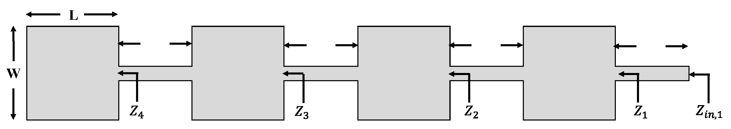
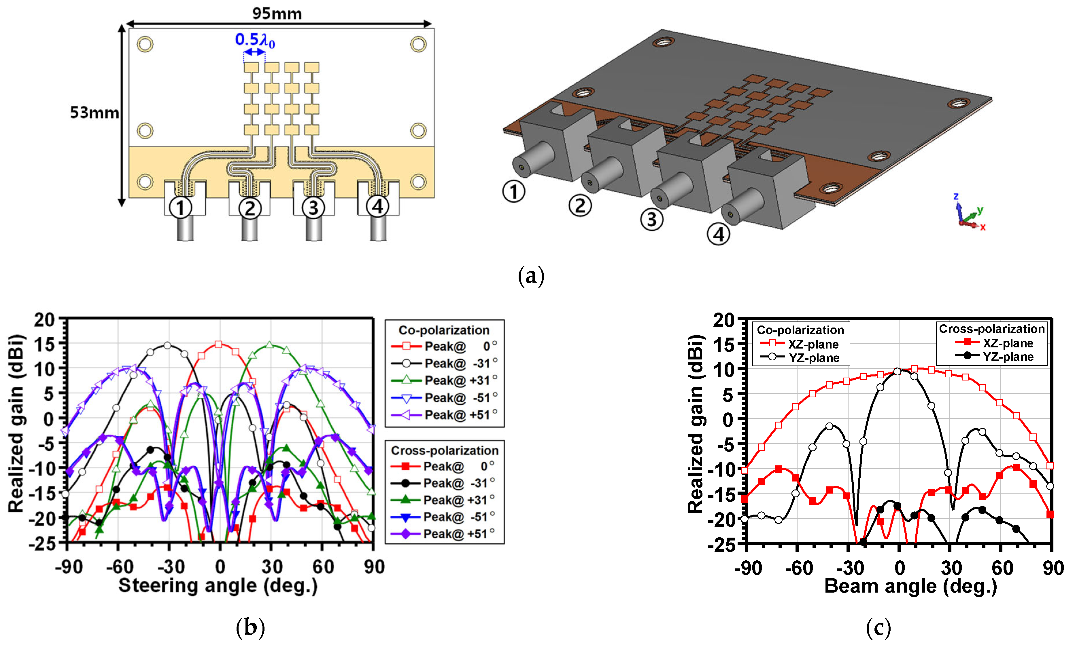
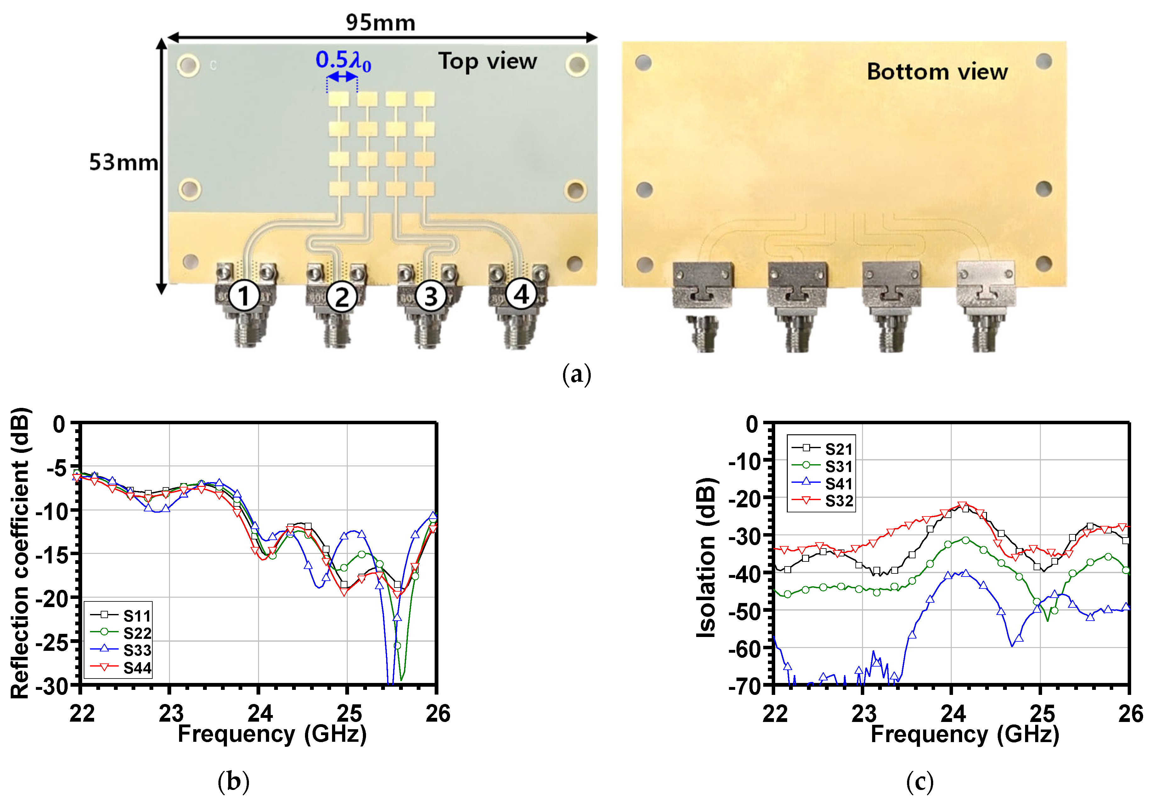
2.1. Series-Fed Uniform Patch Array Antenna Configuration

The antenna array was designed on a Taconic RF-35 substrate, chosen for its low dielectric loss, stable dielectric constant, and compatibility with standard PCB manufacturing processes. The RF-35 substrate features a relative permittivity of 3.5 and a loss tangent of 0.0018. In the 1 × 4 series-fed uniform patch array configuration, four identical rectangular microstrip patch elements are aligned linearly and excited through a continuous series-fed transmission line, as illustrated in Figure 2.
Each individual patch operates in the fundamental TM10 resonant mode at the designated center frequency, and its initial design parameters can be estimated using standard approximate formulas [29]. To achieve an optimal balance between bandwidth, radiation efficiency, and physical compactness, the patch width, W, is determined using the following empirical formula, derived from the cavity model as
W = c 2 f 2 ε r + 1
where c, f, and εr denote the speed of light, center frequency, and relative permittivity, respectively. This expression ensures that the width is sufficiently large to support efficient radiation while preventing unwanted higher-order modes. The dielectric loading effect is characterized by the effective dielectric constant εeff, which captures the influence of fringing fields at the edges of the patch and is expressed as
ε e f f = ε r + 1 2 + ε r 1 2 1 + 12 h W 0.5 ,
where h denotes the height of the dielectric substrate.
The effective resonant length Leff, accounting for the dielectric effects, is determined by
L e f f = c 2 f ε e f f .
Considering the fringing field effect, the actual physical patch length is corrected by subtracting the fringing length, ΔL, as follows.
Δ L = 0.412 h ( ε e f f + 0.3 ) ( W h + 0.264 ) ( ε e f f 0.258 ) ( W h + 0.8 )
Therefore, the final physical patch length becomes
L = L e f f 2 Δ L .
Then, each patch element can be extended into a series array configuration by connecting them through a transmission line. If the feedline between adjacent patch elements has a physical length, l , and characteristic impedance, Z0, the input impedance looking into each radiating stage, starting from the last patch, can be approximated using the following input impedance equations [30]:
Z i n , n = Z 0 Z n + j Z 0 tan β l Z 0 + j Z n tan β l
where Zin,n is the input impedance at the nth element feed line, while Zn is the impedance looking into the nth patch element. Also, β represents the phase constant. For the 4th patch element, the approximated impedance can be given by cavity model analysis as [29]:
Z 4 45 λ 0 W 2 .
Using the transmission line Equation (6), this load impedance was successively transformed step by step back toward the first feed point. Based on the configuration shown in Figure 2, where identical patch elements are employed, the approximated impedance at each stage can be expressed as follows:
Z i n , 4 = Z 0 Z 4 + j Z 0 tan β l Z 0 + j Z 4 tan β l
Z 3 = Z 4 + Z i n , 4
Z i n , 3 = Z 0 Z 3 + j Z 0 tan β l Z 0 + j Z 3 tan β l
Z 2 = Z 4 + Z i n , 3
Z i n , 2 = Z 0 Z 2 + j Z 0 tan β l Z 0 + j Z 2 tan β l
Z 1 = Z 4 + Z i n , 2
and
Z i n , 1 = Z 0 Z 1 + j Z 0 tan β l Z 0 + j Z 1 tan β l .
Equation (8) represents the overall input impedance of the 1 × 4 array, as seen at the input feed point, and it should ideally be matched to the standard impedance of 50 Ω to ensure maximum power transfer and minimize reflection.
Furthermore, the radiated far-field of the 1 × 4 series-fed uniform patch array can be obtained [29] by
E ( θ , ϕ ) = E 0 cos π 2 sin θ sin k W 2 sin θ k W 2 sin θ sin k L 2 cos θ k L 2 cos θ sin 2 k d x sin θ cos ϕ sin k d x sin θ cos ϕ 2
where E0, θ, ϕ, k, and dx represent the normalized amplitude constant, elevation angle, azimuth angle, wave number, and element-to-element spacing, respectively. Equation (9) represents the radiation pattern for each Rx. Then, the radiation pattern for Tx can also be derived by extending the 1 × 4 sub-array to a 4 × 4 array configuration as
E ( θ , ϕ ) = E 0 cos π 2 sin θ sin k W 2 sin θ k W 2 sin θ sin k L 2 cos θ k L 2 cos θ               sin 2 k d x sin θ cos ϕ sin k d x sin θ cos ϕ 2 sin 2 k d y sin θ sin ϕ + α y sin k d y sin θ sin ϕ + α y 2  
where dy and αy denote the sub-array spacing and the phase shift between the 1 × 4 sub-array, respectively. Thus, by controlling the phase shift between the sub-arrays through 4Tx channels of the radar IC, the Tx beam can be steered toward the desired direction, thereby enabling analog beamforming operation at the Tx.

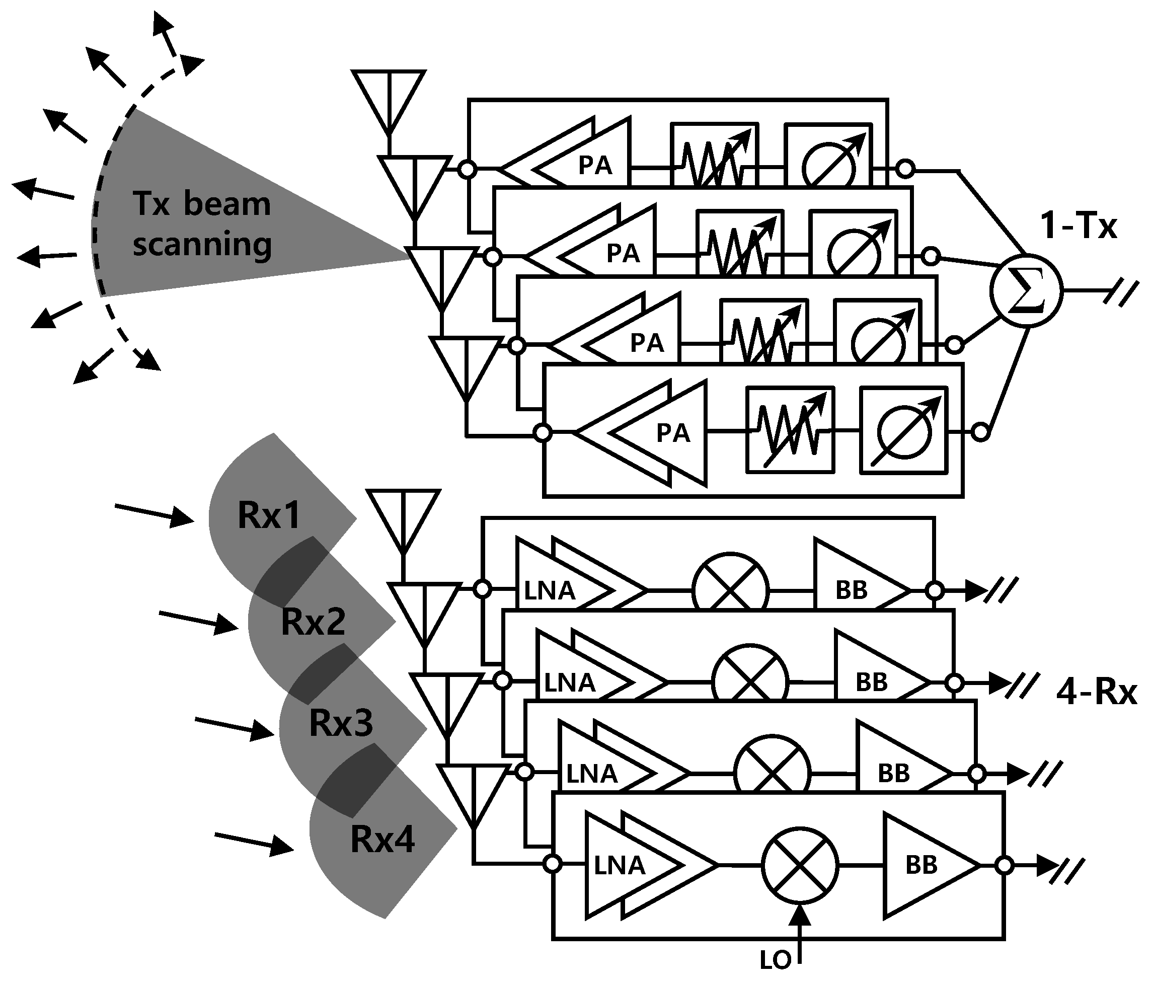
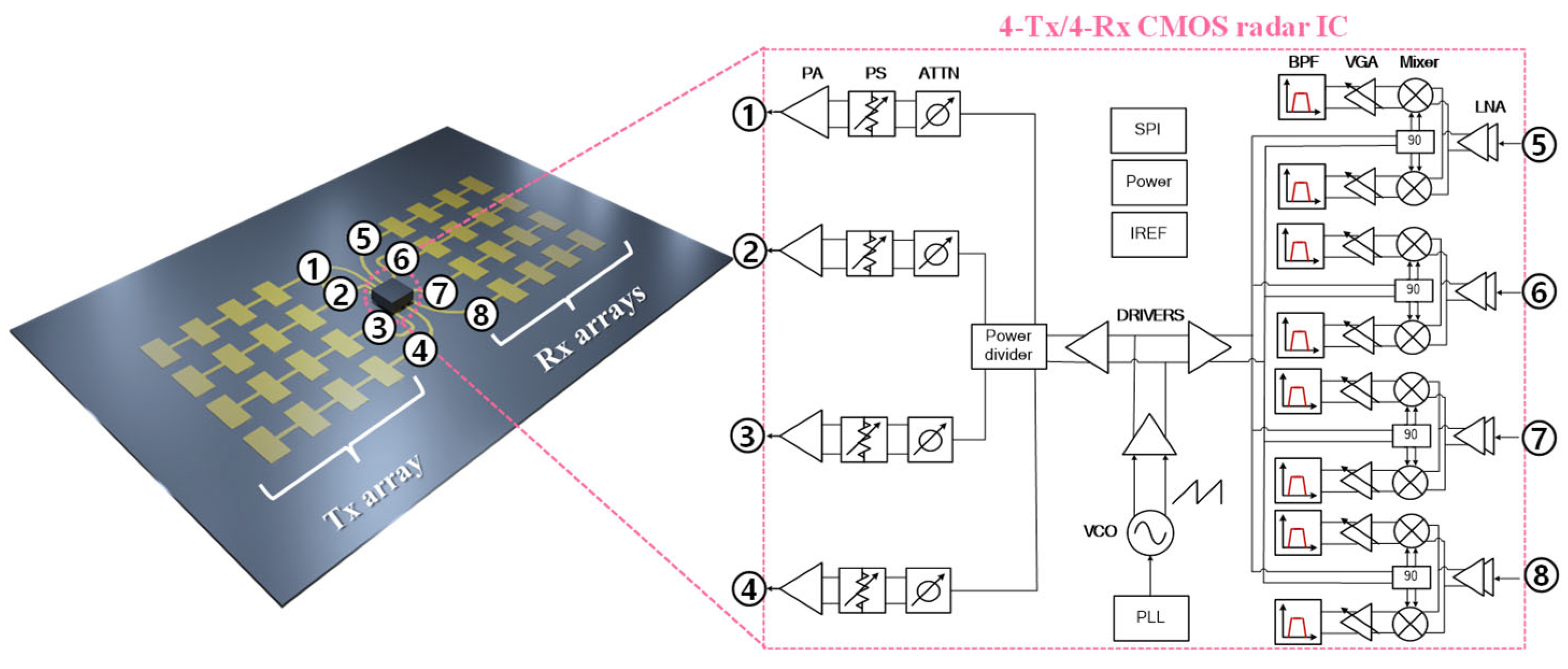
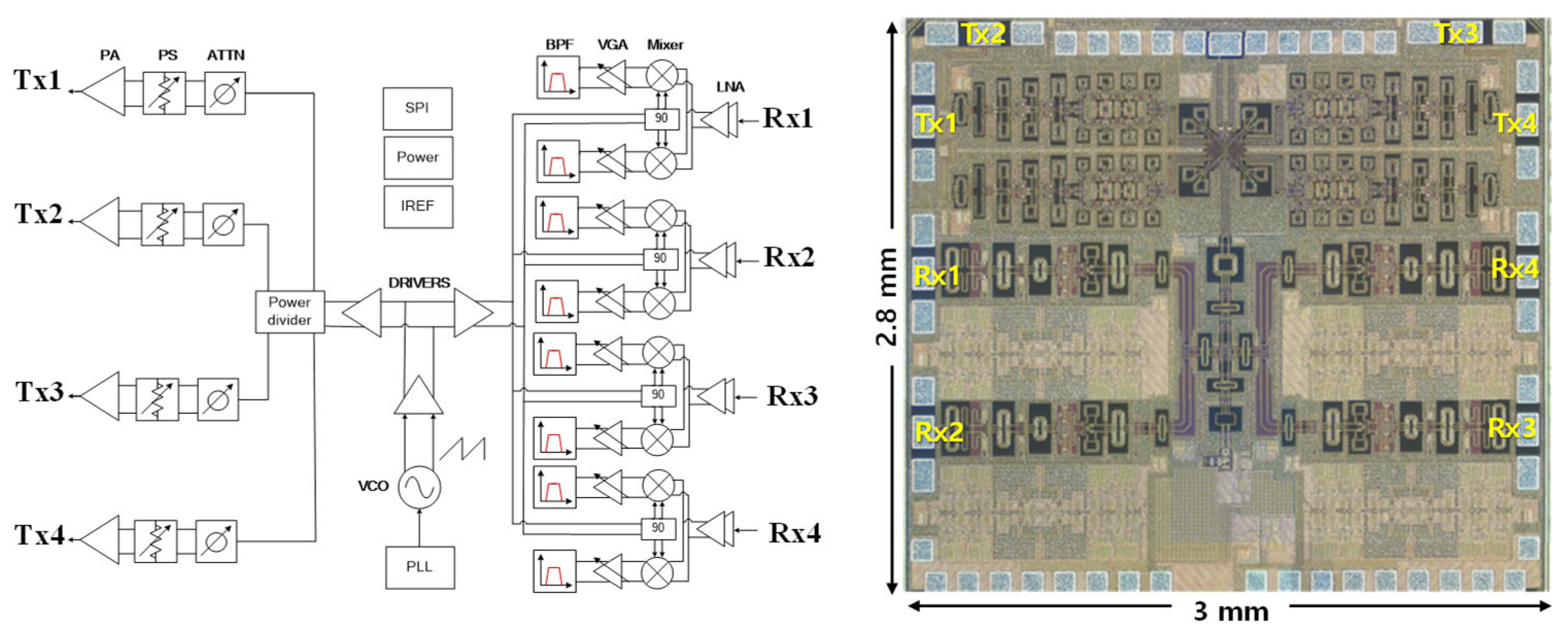
2.2. The 24 GHz 4Tx–4Rx CMOS Radar IC Configuration

The 24 GHz 4Tx and 4Rx CMOS IC is integrated with the series-fed array antennas, as shown in Figure 3. Each Tx chain consists of a power amplifier (PA), phase shifter, and attenuator, enabling beam steering by adjusting the relative phase shift among each chain. On the Rx side, each chain includes a low-noise amplifier (LNA), mixer, transimpedance amplifier (TIA), programmable baseband gain amplifier, and a band-pass filter (BPF). In addition, a phase-locked loop (PLL) and a voltage-controlled oscillator (VCO) are integrated to support frequency-modulated continuous wave (FMCW) operation. Since the 24 GHz CMOS radar IC has already been validated in [31], a detailed analysis of the IC itself is not included in this paper.

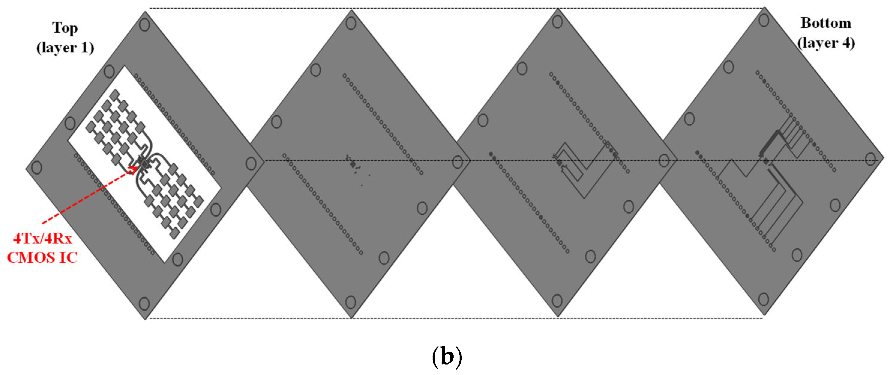
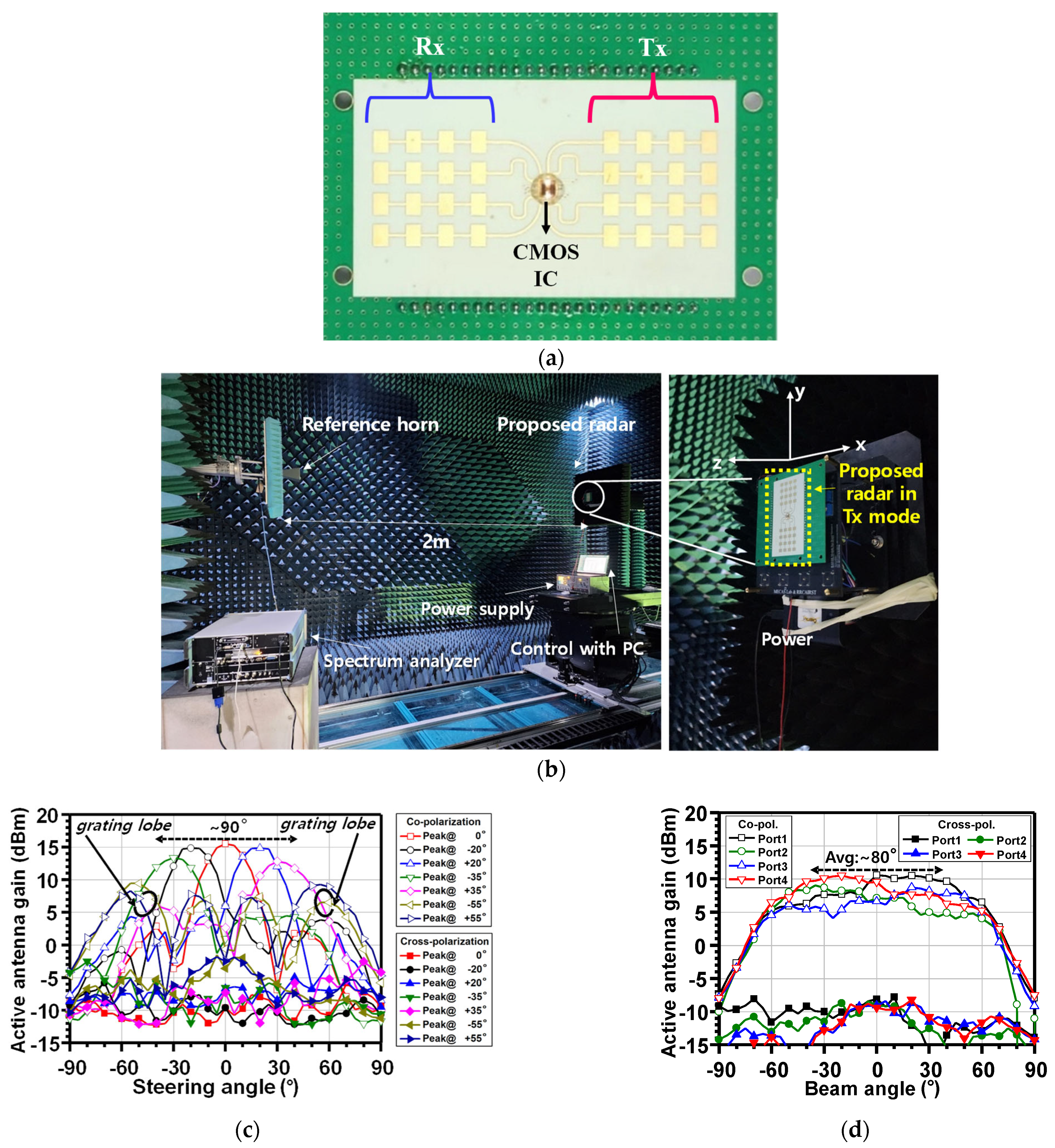
2.3. Fully Integrated Multilayer PCB Configuration

Figure 4a illustrates the multilayer PCB configuration of the proposed radar module, while Figure 4b presents the detailed layer structure. By adopting series-fed array antennas, the design enables coplanar integration of the antenna array and radar IC on a single PCB layer, eliminating the need for antenna feed vias and avoiding the repeated use of expensive low-loss substrate materials. Low-cost FR-4 substrates are employed beneath the antenna’s ground plane within the multilayer PCB stack, effectively reducing both the overall system cost and manufacturing complexity. The relative permittivity of RF-35, RO4450T, and FR-4 are approximately 3.5, 3.5, and 4.3, respectively, while their corresponding loss tangents are about 0.0025, 0.004, and 0.018, respectively.
Additionally, via holes placed near the outer edges of the board to accommodate pin headers, this allows an external DC power supply and control signal access in the event that active components or switching functions are added. The modular PCB structure is carefully designed to minimize parasitic coupling and maintain planar symmetry, which is critical for ensuring predictable radiation characteristics in high-frequency applications.

3. Results

In this section, the simulated and measured results of the array antenna and the beamforming characteristics of the proposed radar are presented. Furthermore, the complete radar performance for small drone detection is evaluated in both the azimuth and elevation planes.

3.1. 24 GHz Radar IC Fabrication

The 4Tx and 4Rx radar was implemented using 65 nm CMOS technology, as shown in Figure 5. The measured phase noise with a 1 MHz offset frequency at 24 GHz was −85.1 dBc/Hz. The RMS frequency error was 350 kHz when measuring the modulated frequency with a 250 MHz chirp bandwidth. Each Tx channel showed an output power of −10 dBm, including bonding wire and connector loss. Thus, a total of −4 dBm output power can be radiated, excluding antenna gain. Also, the total Rx gain, including the RF and analog baseband, was 105 dB, and the total power consumption under FMCW operation with all Txs and Rxs was about 393 mW. Table 1 summarizes the performance of the fabricated 24 GHz CMOS radar IC.
The measured performance of the fabricated CMOS radar IC is summarized in Table 1.

3.2. Series-Fed Array Antenna Simulation and Measurement

Figure 6a illustrates the simulated structure and radiation characteristics of the proposed series-fed antenna array. The array consists of 16 patch elements arranged in a 4 × 4 matrix, with a uniform sub-array spacing of 0.5 λ0. The structure is excited through four independent feed ports, each corresponding to one row of the sub-array, enabling beam steering control via port selection and the excitation phase. As shown in Figure 6b, when all four ports are excited with appropriate amplitude and phase control for the transmitting radiation pattern, successful beam steering is achieved in the XZ-plane. The simulated main beam scanning range covers approximately 91° while maintaining side-lobe levels (SLL) below −10 dB. A peak realized gain of 14.8 dBi is achieved within the scanning range. The co-polarization patterns exhibit a high gain in the intended directions, while the cross-polarization levels remain below −15 dB across the scanned angles, indicating excellent cross-polarization discrimination (XPD). Additionally, Figure 6c shows the radiation performance when only port 1 is excited, representing an Rx radiation pattern. In this case, the HPBW in the XZ-plane is approximately 90°, with realized gains of 10 dBi on the XZ-plane and 9.5 dBi on the YZ-plane. Overall, the simulation results validate the effectiveness of the proposed multilayer PCB-integrated series-fed antenna in achieving high-gain, steerable radiation patterns suitable for radar beamforming while maintaining structural compactness and low implementation complexity.
The fabricated prototype of the proposed series-fed antenna array is shown in Figure 7a, presenting both the top and bottom views of the multilayer PCB along with four SMA connectors corresponding to each input port. The measured reflection coefficients for ports 1 to 4 are depicted in Figure 7b. The antenna exhibits a minimum −10 dB impedance bandwidth from 23.9 GHz to 26 GHz, corresponding to a fractional bandwidth of approximately 8.3% centered at 24.95 GHz. Additionally, the port-to-port isolation characteristics are shown in Figure 7c. Across the operating frequency band, all measured isolation values exceed 21 dB, with several surpassing 40 dB, demonstrating excellent decoupling between antenna ports. These results confirm that the fabricated antenna array maintains good impedance matching and isolation performance, consistent with simulation predictions, thereby validating its suitability for multiport radar and beamforming applications.

3.3. Radar Beam-Pattern Measurement

The complete radar system was implemented, as shown in Figure 8a. The antenna was fabricated on a multilayer PCB and integrated with the radar transceiver IC using chip-on-board (COB) bonding. The radiation characteristics of the fully assembled radar module were then measured in a millimeter-wave (mmWave) anechoic chamber, as depicted in Figure 8b. The measured Tx beam steering patterns, obtained through analog beamforming, demonstrated a peak gain of approximately 15 dBi. The 3 dB beam scanning range covered ±45° in the XZ-plane; beyond this range, grating lobes emerged, making those angles unsuitable for radar operation. Additionally, the radiation pattern of a single sub-array was measured, as shown in Figure 8d, to indirectly assess the received (Rx) radiation characteristics. The average measured HPBW in the XZ-plane was approximately 80°, confirming the Rx array’s suitability for target detection in short-range radar applications.

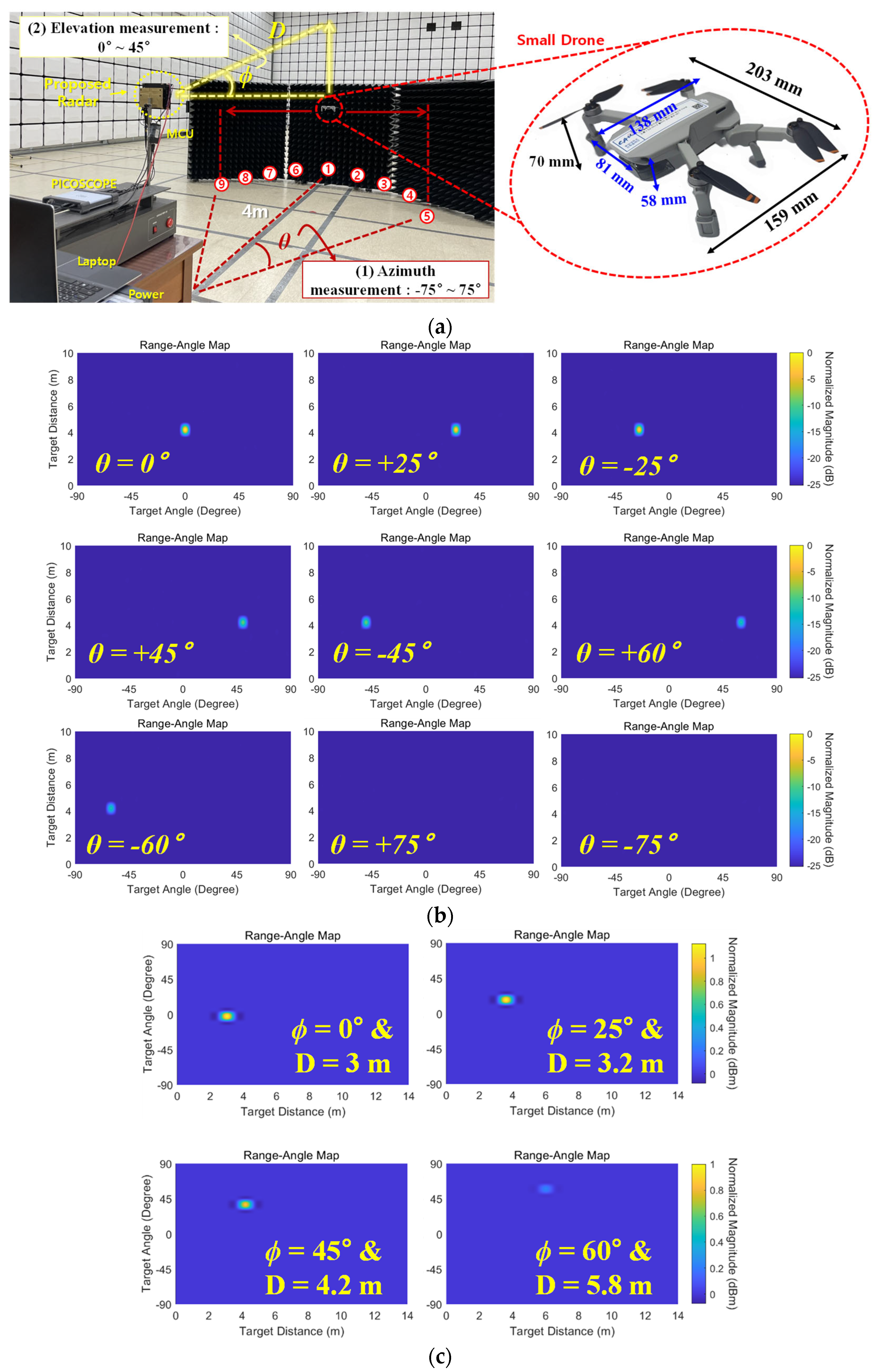
3.4. Small Drone Detection Test

To evaluate the real-world radar sensing capabilities of the proposed radar module, a detection experiment was conducted in a semi-anechoic chamber using a compact quadcopter drone as the target, as shown in Figure 9a. The drone’s overall dimensions, including the wings and landing legs, measured 159 mm × 203 mm × 70 mm, while the core body alone measured 138 mm × 81 mm × 58 mm, representative of the typical small aerial platforms used in civilian and security applications. To comprehensively assess detection performance across both azimuth and elevation angles, two sets of measurements were performed. For the azimuth range-angle experiment, the drone was positioned 4 m from the radar and moved horizontally to generate varying azimuth angles. For the elevation range-angle experiment, the drone was again placed 4 m away but moved vertically to produce different elevation angles, as illustrated in Figure 9a.
The measured azimuth range-angle maps are shown in Figure 9b. The radar successfully detected the drone at azimuth angles of up to ±60°, but detection failed beyond ±75°. The measured elevation range-angle maps, presented in Figure 9c, focused exclusively on airborne targets by considering only elevation angles above ground level. The diagonal distance, D, from the radar to the drone at each elevation angle was also indicated. The radar reliably detected the drone at elevation angles of up to 45°, while detection at 60° showed noticeably weaker signal intensity, suggesting that reliable detection at this angle may be limited under practical conditions.

4. Discussion

To quantitatively evaluate the proposed radar’s ability to detect small aerial targets such as a compact quadcopter, the radar range equation can be considered. It describes the relationship between the transmitted power, antenna characteristics, propagation loss, and the received echo power after reflection from the target. The maximum detectable range Rmax in relation to the signal-to-noise ratio (SNR) is given by [31]
R m a x = P t G t G r λ 2 σ ( 4 π ) 3 SNR m i n k T 0 B F L 1 4
where Pt, Gt, Gr, σ, L, k, T0, B, and F represent the Tx power, Tx antenna gain, Rx antenna gain, radar cross-section (RCS), system losses, Boltzmann constant (1.38 × 10⁻²³ J/K), system temperature, Rx bandwidth, and Rx noise factor, respectively. Based on the radar parameters applied in the experiment, the following conditions were considered for detection range estimation. The total transmit power Pt was −4 dBm, equivalent to approximately 0.4 mW, and the transmit antenna exhibited a gain of 15 dBi, corresponding to a linear gain factor of approximately 31.6. The receive antenna had an average gain of 8 dBi, corresponding to a linear factor of 6.31. The operating wavelength λ at 24 GHz was calculated as approximately 0.0125 m. The RCS of the target drone was estimated at 0.0142 m2 based on its physical dimensions. Additionally, the receiver’s noise figure, when converted to a noise factor, was approximately 39.8. As the complete radar system was fully integrated, system losses were assumed negligible, and the minimum required SNR for small drone detection was set at approximately 0 dB. Finally, since the experiment focused on verifying hybrid beamforming techniques for target detection rather than range resolution, the receiver bandwidth was narrowly set to 1 MHz.
Using these parameters within a radar link budget analysis, the calculated maximum detection distance Rmax was approximately 4.86 m. According to Figure 9c, the elevation angle at 45° corresponded to a diagonal distance of 4.2 m, which was within the calculated Rmax, and thus, the target was reliably detected. At an elevation angle of 60°, corresponding to a distance of 5.8 m, the detection on the range-angle map was weaker and less distinct, as this exceeded the calculated Rmax for the minimum SNR of 0 dB, confirming that the measurement aligned well with the budget analysis. Overall, the small drone detection results show strong agreement with the theoretical expectations derived from the radar range equation, which accounts for transmitted power, antenna gains, target RCS, propagation effects, and system losses. The radar equation thus provides a robust framework for interpreting experimental observations and guides the design and optimization of radar systems for short-range detection scenarios. It enables a quantitative understanding of how key parameters influence system performance and supports the development of efficient sensing strategies for UAV monitoring and related applications.

5. Conclusions

This paper has presented the design, implementation, and experimental validation of a compact 24 GHz hybrid beamforming radar system that integrates series-fed array antennas with a multi-channel CMOS radar IC for efficient small drone detection. By combining analog beamforming on the transmitter side with multi-channel digital reception on the receiver side, the proposed radar achieves an effective balance between system simplicity, low hardware complexity, and high spatial resolution. The integration of four 1 × 4 series-fed patch antenna sub-arrays directly onto a multilayer PCB, along with a 4Tx and 4Rx CMOS radar transceiver IC, enables a compact, low-cost, and power-efficient solution suitable for short-range surveillance applications. The experimental validation included comprehensive small drone detection tests, where the radar reliably detected a compact quadcopter at azimuth angles of up to ±60° and elevation angles of up to 45°, closely matching the theoretical predictions derived from the radar range equation and link budget analysis. Although real-time tracking remains future work, this paper presents a practical and scalable radar architecture that integrates compact antenna design, hybrid beamforming, and CMOS radar technology to address the challenges of detecting low-RCS aerial targets in short-range applications. These results provide valuable insights into the co-design of antenna arrays and radar circuits for high-performance, low-power sensing platforms, paving the way for future UAV surveillance, security monitoring, and autonomous navigation systems.

Author Contributions

Writing—original draft preparation, K.J.; investigation and validation, S.-S.H.; writing—review and editing, H.L.L.; supervision, D.B. All authors have read and agreed to the published version of the manuscript.

Funding

This work was supported in part by the Institute of Information & Communications Technology Planning & Evaluation (IITP) grant funded by the Korea Government (MSIT) (No. 2019-0-00138, Development of Intelligent Radar Platform Technology for Smart Environments) and in part by the Chung-Ang University Young Scientist Scholarship in 2023.

Data Availability Statement

The original contributions presented in this study are included in the article. Further inquiries can be directed to the corresponding author.

Conflicts of Interest

The authors declare no conflicts of interest.

References

  1. Eiadkaew, S.; Boonpoonga, A.; Phaebua, K.; Athikulwongse, K.; Shutimarrungson, N. Design and Experiment of FMCW Radar System for Drone Detection. In Proceedings of the 37th International Technical Conference on Circuits/Systems, Computers and Communications (ITC-CSCC), Phuket, Thailand, 5–8 July 2022. [Google Scholar]
  2. Mughal, A.M.; Shahid, A.; Shaukat, M.Z.; Ashraf, M.A.; Ullah, T. Drone Detection and Classification on Micro-Doppler Signatures Using FMCW Radar. In Proceedings of the 20th International Bhurban Conference on Applied Sciences and Technology (IBCAST), Bhurban, Murree, Pakistan, 22–25 August 2023. [Google Scholar]
  3. Liu, Z.; An, P.; Yang, Y.; Qiu, S.; Liu, Q.; Xu, X. Vision-Based Drone Detection in Complex Environments: A Survey. Drones 2024, 8, 643. [Google Scholar] [CrossRef]
  4. Ezuma, M.; Anjinappa, C.K.; Semkin, V.; Guvenc, I. Comparative Analysis of Radar-Cross-Section-Based UAV Recognition Techniques. IEEE Sens. J. 2022, 22, 17932–17949. [Google Scholar] [CrossRef]
  5. Chu, X.; Zhou, X.; Bu, Q.; Miao, Q. Sensor Fault Detection for UAVs Using Improved Self-Attention LSTM Network with Similarity Space Mapping. IEEE Trans. Instrum. Meas. 2025, 73, 1–12. [Google Scholar] [CrossRef]
  6. Ye, N.; Walker, J.P.; Gao, Y.; PopStefanija, I.; Hills, J. Comparison Between Thermal-Optical and L-Band Passive Microwave Soil Moisture Remote Sensing at Farm Scales: Towards UAV-Based Near-Surface Soil Moisture Mapping. IEEE J. Sel. Top. Appl. Earth Obs. Remote Sens. 2024, 17, 633–642. [Google Scholar] [CrossRef]
  7. Rahman, S.; Robertson, D.A. FAROS-E: A Compact and Low-Cost Millimeter Wave Surveillance Radar for Real-Time Drone Detection and Classification. In Proceedings of the 21st International Radar Symposium (IRS), Berlin, Germany, 21–22 June 2021; pp. 1–6. [Google Scholar]
  8. Ivancic, J.; Alves, F. Directional Multi-Resonant Micro-Electromechanical System Acoustic Sensor for Low Frequency Detection. Sensors 2024, 24, 2908. [Google Scholar] [CrossRef]
  9. Semenyuk, V.; Kurmashev, I.; Lupidi, A.; Alyoshin, D.; Kurmasheva, L.; Cantelli-Forti, A. Advances in UAV Detection: Integrating Multi-Sensor Systems and AI for Enhanced Accuracy and Efficiency. Int. J. Crit. Infrastruct. Prot. 2025, 49, 100744. [Google Scholar] [CrossRef]
  10. Prasad, S.V.R.V.; Khilar, P.M. SVM-SFL Based Malicious UAV Detection in Wireless Sensor Networks. Concurr. Comput. Pract. Exp. 2024, 36, e8049. [Google Scholar] [CrossRef]
  11. Qiu, L.; Zhou, D.; Wang, Y.; Chu, Q.; Zhu, Z.; Li, T.; Dong, Y. Dynamic Distributed Pressure Measurement Using Frequency-Agile Fast BOTDA. IEEE Sens. J. 2021, 21, 25743–25748. [Google Scholar] [CrossRef]
  12. Abdelnasser, H.; McCann, J.A. Drone Propeller Speed Measurement: Case Study Using 5GHz RF and mmWave Radar. In Proceedings of the IEEE 99th Vehicular Technology Conference (VTC2024-Spring), Singapore, 24–27 June 2024; pp. 1–6. [Google Scholar]
  13. Bhatia, J.; Dayal, A.; Jha, A.; Vishvakarma, S.K.; Joshi, S.; Srinivas, M.B.; Yalavarthy, P.K.; Kumar, A.; Lalitha, V.; Koorapati, S.; et al. Classification of Targets Using Statistical Features from Range FFT of mmWave FMCW Radars. Electronics 2021, 10, 1965. [Google Scholar] [CrossRef]
  14. de Cos Gómez, M.E.; Flórez Berdasco, A.; Las-Heras Andrés, F. Eco-Friendly Metadome-Antenna Innovations for Wearable Millimeter Wave Radar Sensing. Appl. Sci. 2025, 15, 2674. [Google Scholar] [CrossRef]
  15. Huebner, K.C.; Tegowski, B.; Koelpin, A. A Six-Port-Based Tracking System for Automated Landing of Fixed-Wing UAVs. In Proceedings of the 25th International Microwave and Radar Conference (MIKON), Wroclaw, Poland, 1–4 July 2024. [Google Scholar]
  16. Chaky, R.J.; Beneck, R.J.; Campbell, S.D.; Werner, D.H. Simultaneous Optimization of 1-bit 3-D Coding Meta-Volumes for Both Broadband and Wide Field-of-View Radar Cross-Section Reduction. IEEE Trans. Antennas Propag. 2023, 71, 3361–3370. [Google Scholar] [CrossRef]
  17. Li, Y.; Zhang, Y.; Han, Z.; Tang, S.; Jing, L.; Chiu, C.Y.; Murch, R. Analog Precoding Using Highly Reconfigurable Antennas. IEEE Wirel. Commun. Lett. 2020, 9, 648–652. [Google Scholar] [CrossRef]
  18. Zhang, C.; Shen, S.; Han, Z.; Murch, R. Analog Beamforming Using ESPAR for Single-RF Precoding Systems. IEEE Trans. Wirel. Commun. 2023, 22, 4387–4400. [Google Scholar] [CrossRef]
  19. Ragonese, E.; Papotto, G.; Nocera, C.; Cavarra, A.; Palmisano, G. CMOS Automotive Radar Sensors: mm-Wave Circuit Design Challenges. IEEE Trans. Circuits Syst. II Express Briefs 2022, 69, 2610–2616. [Google Scholar] [CrossRef]
  20. Tschoban, C.B.; Pötter, H.; Dilek, S.; Ndip, I.; Schneider-Ramelow, M. Integratable Antenna Concepts Based on Conformal Antennas for 3D Radar Systems. In Proceedings of the International Workshop on Antenna Technology (iWAT), Aalborg, Denmark, 15–17 May 2023. [Google Scholar]
  21. Lee, S.; Yoon, D.; Hwang, K.; Wang, H.; Park, K.-H.; Bae Park, Y. Wideband Fan-Beam Lens Antenna for IR-UWB Through-the-Wall Human Detection Radar. IEEE Sens. J. 2025, 25, 11246–11257. [Google Scholar] [CrossRef]
  22. Lee, C.U.; Noh, G.; Ahn, B.K.; Yu, J.-W.; Lee, H.L. Tilted-Beam Switched Array Antenna for UAV Mounted Radar Applications with 360° Coverage. Electronics 2019, 8, 1240. [Google Scholar] [CrossRef]
  23. Lee, H.; Kim, Y.-B.; Lee, H.L. Reconfigurable Antenna for UAV-Assisted Wide Coverage Air-to-Ground Communications. IEEE Access 2022, 10, 88034–88042. [Google Scholar] [CrossRef]
  24. Lee, H.L.; Park, D.-H.; Lee, M.-Q.; Yu, J.-W. Reconfigurable 2 × 2 Multi-Port Amplifier Using Switching Mode Hybrid Matrices. IEEE Microw. Wirel. Compon. Lett. 2014, 24, 129–131. [Google Scholar] [CrossRef]
  25. Dong, H.-J.; Kim, Y.-B.; Lee, H.L. Reconfigurable Quad-Polarization Switched Beamforming Antenna with Crossed Inverted-V Array and Dual-Butler Matrix. IEEE Trans. Antennas Propag. 2022, 70, 2708–2716. [Google Scholar] [CrossRef]
  26. Kim, Y.-J.; Kim, Y.-B.; Dong, H.-J.; Cho, Y.S.; Lee, H.L. Compact Switched-Beam Array Antenna with a Butler Matrix and a Folded Ground Structure. Electronics 2020, 9, 2. [Google Scholar] [CrossRef]
  27. Li, X.; Zhang, Y.; Wang, H. Practical Investigation of a MIMO Radar System Capabilities for Small Drones Detection. Remote Sens. 2022, 14, 1016. [Google Scholar]
  28. Wei, Z.; Zhang, F.; Chang, S.; Liu, Y.; Wu, H.; Feng, Z. Comprehensive Review: Effectiveness of MIMO and Beamforming for UAV Detection. Remote Sens. 2024, 16, 1016. [Google Scholar]
  29. Balanis, C.A. Antenna Theory: Analysis and Design; Wiley: Hoboken, NJ, USA, 1982. [Google Scholar]
  30. Pozar, D.M. Microwave Engineering, 4th ed.; Wiley: Hoboken, NJ, USA, 2012. [Google Scholar]
  31. Lee, J.; Lee, H.; Ko, G.-H.; Baek, D.; Lee, H.L. Compact and Highly Efficient Short-Range Radar for Advanced Driver Assistant Systems. IEEE Trans. Veh. Technol. 2023, 72, 1629–1637. [Google Scholar] [CrossRef]
Figure 1. Overview of the proposed hybrid beamforming method.
Drones 09 00453 g001
Figure 2. Series-fed array antenna structure and design parameters.
Drones 09 00453 g002
Figure 3. The 4Tx–4Rx CMOS IC of the proposed radar.
Drones 09 00453 g003
Figure 4. Fully integrated multilayer PCB configuration with (a) layer information and (b) detailed layer view.
Drones 09 00453 g004aDrones 09 00453 g004b
Figure 5. Fabricated 24 GHz CMOS radar IC.
Drones 09 00453 g005
Figure 6. Designed series-fed patch array with (a) a 3D simulation model, (b) simulated scan angles in the XZ-plane at 24 GHz, and a (c) simulated HPBW with single-port excitation.
Drones 09 00453 g006
Figure 7. Implementation of the series-fed array antenna with (a) top and bottom views, measured (b) reflection coefficients, and (c) isolation among each port.
Drones 09 00453 g007
Figure 8. Proposed hybrid beamforming radar with (a) implementation, (b) radiation pattern measurement setup, (c) measured analog beam steering patterns for Tx, and (d) measured single sub-array radiation pattern for Rx in the XZ-plane.
Drones 09 00453 g008
Figure 9. Drone detection test with (a) measurement description, (b) measured azimuth direction profile, and (c) measured elevation direction profile results.
Drones 09 00453 g009
Table 1. Summary of the CMOS radar IC.
ParametersValueParametersValue
Phase Noise−85.1 dBc/HzRx max. gain105 dB
RMS freq. error350 kHzRx NF16 dB
Total Tx max. power−4 dBmChip area8.4 mm2
PA PAE @ −10 dBm34%Power consumption4393 mW
Disclaimer/Publisher’s Note: The statements, opinions and data contained in all publications are solely those of the individual author(s) and contributor(s) and not of MDPI and/or the editor(s). MDPI and/or the editor(s) disclaim responsibility for any injury to people or property resulting from any ideas, methods, instructions or products referred to in the content.

