Article

UAV Spiral Maneuvering Trajectory Intelligent Generation Method Based on Virtual Trajectory

1
College of Missle Engineering, Rocket Force University of Engineering, Xi’an 710025, China
2
Department of Automation, Tsinghua University, Beijing 100084, China
*
Author to whom correspondence should be addressed.
Drones 2025, 9(6), 446; https://doi.org/10.3390/drones9060446
Submission received: 24 April 2025 / Revised: 30 May 2025 / Accepted: 11 June 2025 / Published: 18 June 2025

Abstract

:
This paper addresses the challenge of ineffective coordination between terminal maneuvering and precision strike capabilities in hypersonic unmanned aerial vehicles (UAVs). To resolve this issue, an intelligent spiral maneuver trajectory generation method utilizing a virtual trajectory framework is proposed. Initially, a relative motion model between the UAV and the virtual center of mass (VCM) is established based on the geometric principles of the Archimedean spiral. Subsequently, the interaction dynamics between the VCM and the target are formulated as a Markov decision process (MDP). A deep reinforcement learning (DRL) approach, employing the proximal policy optimization (PPO) algorithm, is implemented to train a policy network capable of end-to-end virtual trajectory generation. Ultimately, the relative spiral motion is superimposed onto the generated virtual trajectory to synthesize a composite spiral maneuvering trajectory. The simulation results demonstrate that the proposed method achieves expansive spiral maneuvering ranges while ensuring precise target strikes.

1. Introduction

As various countries around the world actively develop technologies and equipment against hypersonic unmanned aerial vehicles (UAVs), the future interception airspace will be fully covered, and the penetration channels will be closed. The penetration situation of hypersonic UAVs will become increasingly severe. Developing effective technologies and methods to counter the penetration of defense weapons has extremely important strategic significance [1,2,3].
During the terminal phase of precision ground strikes, hypersonic UAVs experience rapid decreases in altitude and velocity, rendering them more susceptible to enemy detection and interception compared to the mid-course phase [4]. The implementation of pre-programmed maneuver penetration tactics represents a prevalent countermeasure during this terminal phase [5]. This method can break the law of trajectory prediction, reduce the effectiveness of the anti-identification technology of enemy trajectory prediction, and mislead the movement of the interceptor through wrong prediction information, increase the maneuvering overload of the interceptor, and even lead to the overload and saturation of the interceptor and the loss of target tracking ability of the seeker [6,7], which interrupts the engagement link in the kill chain and improves the penetration probability.
The common maneuvering forms of programmed maneuvering penetration include snake maneuvering, pendulum maneuvering and spiral maneuvering [8]. As a complex three-dimensional maneuvering mode, spiral maneuvering has the advantages of large maneuvering amplitude, time-varying maneuvering frequency and unpredictable ballistic trajectory, which can greatly improve the penetration probability of UAVs [9,10,11]. Contemporary spiral maneuvering methodologies primarily comprise two trajectory variants: the non-convergent cylindrical spiral [12,13,14] and progressively convergent conical spiral [15,16,17]. The studies in Refs. [12,13] formulate a guidance law through variable structure control theory to track the line-of-sight (LOS) angle rate and execute spiral maneuvers, utilizing sinusoidal functions to govern the LOS angle rate dynamics. However, this approach exhibits limitations due to the distance-dependent variability in the LOS angle rate amplitude and periodicity, which introduces nonstationary trajectory characteristics. Consequently, the spiral radius and frequency cannot be prescriptively optimized, as their design remains contingent on dynamic operational constraints. Ref. [14] addresses low-speed UAV applications by proposing a guidance law that generates fixed-amplitude spiral trajectories around cylindrical virtual paths through periodic cosine-based deviations. While effective for low-velocity regimes, this method necessitates excessive control authority (i.e., high overload demands) in high-speed scenarios to maintain post-maneuver guidance accuracy, significantly degrading strike precision under kinematic constraints. Further methodologies include the integration of spiral angular velocity vectors with proportional navigation guidance in Ref. [15], where spiral commands diminish proportionally to the speed-leading angle. This results in inflexible maneuver amplitude and frequency modulation. Similarly, Ref. [16] incorporates a height-dependent sinusoidal acceleration bias into a sliding-mode guidance framework to generate spiral trajectories, though precise amplitude regulation remains unattainable. In Ref. [17], an adaptive proportional guidance law tracks logarithmic spiral trajectories for terminal dive maneuvers. While enabling spiral strikes from elevated positions, this strategy induces substantial velocity loss, compromising both penetration efficacy and kinetic energy retention during terminal engagement.
Although spiral maneuvering penetration is achieved in the mentioned references, there still exist some limitations. In contemporary UAV development, a critical focus lies in advancing intelligent perception and maneuvering capabilities to enable autonomous evasion, dynamic trajectory adjustment and precision targeting. Recent advancements in active evasive maneuvering systems for UAVs have demonstrated incremental progress toward technical viability. However, such evasion strategies—particularly during penetration scenarios—risk significant deviations from predefined trajectories [12]. To address this challenge, UAVs must integrate adaptive control mechanisms capable of executing timely directional corrections. These adjustments are essential to reconciling evasion success with mission-critical accuracy, ensuring the system avoids compromise while maintaining the capacity to deliver precise strikes post-maneuver.
Deep reinforcement learning (DRL) has emerged as a prominent research focus within the artificial intelligence domain. Owing to its advanced decision-making capabilities, DRL has facilitated significant breakthroughs in the development of control strategies for hypersonic UAVs, particularly in enhancing autonomous maneuver evasion and precision guidance systems. These advancements underscore DRL’s potential to address complex challenges in high-speed dynamic environments, where adaptive and real-time trajectory optimization is critical to mission success. In Ref. [18], an online multi-constraint re-entry guidance was achieved based on the improved hindsight experience replay method and the deep deterministic policy gradient algorithm. To address comprehensive flying object dynamics and the control mechanism, the Markov decision process (MDP) is used to solve the guidance and control problem, thereby achieving intelligent guidance laws for time control [19,20] and attack angle control [21,22] within the constraint of the field of view. In Ref. [23], to improve the survivability of the UAV in the face of multiple interceptors, the penetration process is conceptualized as a generalized three-body adversarial optimal problem, then modeled as a MDP, with a DRL scheme to solve this. In response to the issue of the UAV escape guidance, a unified intelligent control strategy synthesizing optimal guidance and meta DRL has been proposed in Ref. [4] and maneuvering strategies that combine LOS angle rate correction with DRL have been proposed in Ref. [24], which can achieve highly precise guidance and effective escape.
Building on the aforementioned insights, this study investigates a real-time spiral maneuvering trajectory generation framework integrated with DRL to reconcile the inherent tension between evasion efficacy and strike precision. The primary contributions of this work are as follows:
1.
A virtual trajectory-based spiral maneuvering trajectory design method is proposed to realize efficient coordination between maneuver penetration and precision strike;
2.
The Archimedes spiral is used in the design of the relative spiral, and the maneuvering amplitude and maneuvering frequency can be adjusted;
3.
Combined with DRL to generate virtual trajectories, the hypersonic UAV can sense the target in real time during flight, effectively adjust the maneuvering trajectory, and achieve accurate strikes on moving targets.
The organizational structure of this paper is delineated as follows: Section 2 presents the foundational mathematical frameworks, encompassing the hypersonic UAV dynamics model, spiral maneuvering trajectory formulation. Section 3 introduces a relative spiral motion paradigm grounded in Archimedes spiral geometry. A virtual reference trajectory generation methodology is rigorously derived using DRL principles, and the synthesized spiral maneuvering trajectory is realized through the kinematic superposition of relative motion dynamics onto the virtual trajectory. In order to verify the effectiveness, feasibility and real-time performance of the proposed method, simulation verification is carried out in Section 4. In Section 5, the paper’s conclusions are summarized.

2. Modeling of Spiral Maneuver Trajectory

2.1. Modeling of the UAV Motion

The three-degree-of-freedom motion equation is adopted to describe the UAV and the dynamic equation is established in the ballistic coordinating system [17]:
x ˙ = V cos γ cos ψ y ˙ = V sin γ z ˙ = V cos γ sin ψ V ˙ = D m g sin γ γ ˙ = L cos σ m V g V cos γ ψ ˙ = L sin σ m V cos γ
where ( x , y , z ) is the position of the UAV in the inertial system, V is the speed, γ is the velocity slope angle, ψ is the velocity azimuth, σ is the bank angle, m is the mass, g = 9.81 m/s2 is the gravitational acceleration, and ( D , L ) are, respectively, drag force and lift force, whose expression is as follows:
L = 1 2 ρ V 2 C L S ref D = 1 2 ρ V 2 C D S ref
where C L and C D are the drag and lift coefficient, S ref is reference area of the UAV and ρ is the density of the atmosphere, using the following exponential atmospheric model:
ρ = ρ 0 e H / H s
where ρ 0 is the sea level atmospheric density, H s = 6700 m is the equivalent density height of the earth atmosphere, H = r R 0 is the height of the UAV and R 0 is the radius of the Earth.

2.2. Kinematic Modeling with Virtual Center of Mass

The spiral maneuvering trajectory is generated through the relative spiral motion of the UAV around a virtual reference trajectory that ensures terminal strike precision. Consequently, establishing a rigorous analytical framework to characterize the kinematic transformation and relative motion dynamics between the UAV and the virtual center of mass (VCM) is imperative to optimize evasion-strike coordination.

2.2.1. Definition and Transformation of Coordinate System

Definition 1: The VCM is a particle with only velocity and position.
Definition 2: The virtual trajectory is formed by the position of the VCM at every moment of flight to the target according to the guidance law.
The schematic diagram of the spiral maneuver trajectory is shown in Figure 1, O X Y Z representing the inertial system, M v T the virtual trajectory, M v VCM, M r T the spiral maneuver penetration trajectory and M r the UAV center of mass.
To enable precise state estimation of the UAV, a virtual center-of-mass-referenced coordinate system is formulated based on the methodological framework of classical flight mechanics reference frames.
1.
A virtual ballistic coordinate system, denoted as M v X v 1 Y v 1 Z v 1 , is rigorously defined with its origin M v positioned at the VCM. The M v X v 1 -axis is aligned with the velocity vector of the VCM, the M v Y v 1 -axis is orthogonally oriented upward within the vertical plane relative to M v X v 1 and the M v Z v 1 -axis is determined via the right-hand rule to complete the orthonormal triad.
2.
A virtual LOS coordinate system, denoted as M v X s 1 Y s 1 Z s 1 , is rigorously defined with its origin M v positioned at the VCM. The M v X s 1 -axis is aligned with the target vector, the M v Y s 1 -axis is orthogonally oriented upward within the vertical plane relative to M v X s 1 and the M v Z s 1 -axis is determined via the right-hand rule to complete the orthonormal triad.
Analogously, the ballistic coordinate system M r X r 1 Y r 1 Z r 1 and LOS coordinate system M r X s 2 Y s 2 Z s 2 for the UAV are constructed through the aforementioned methodological framework. The Euler angle transformations between these coordinate systems are derived through a “2–3" rotation sequence, as delineated in Table 1.
According to the Euler angle relationship between the coordinate systems in Table 1, the corresponding transformation matrix can be obtained.

2.2.2. Relative Motion Model

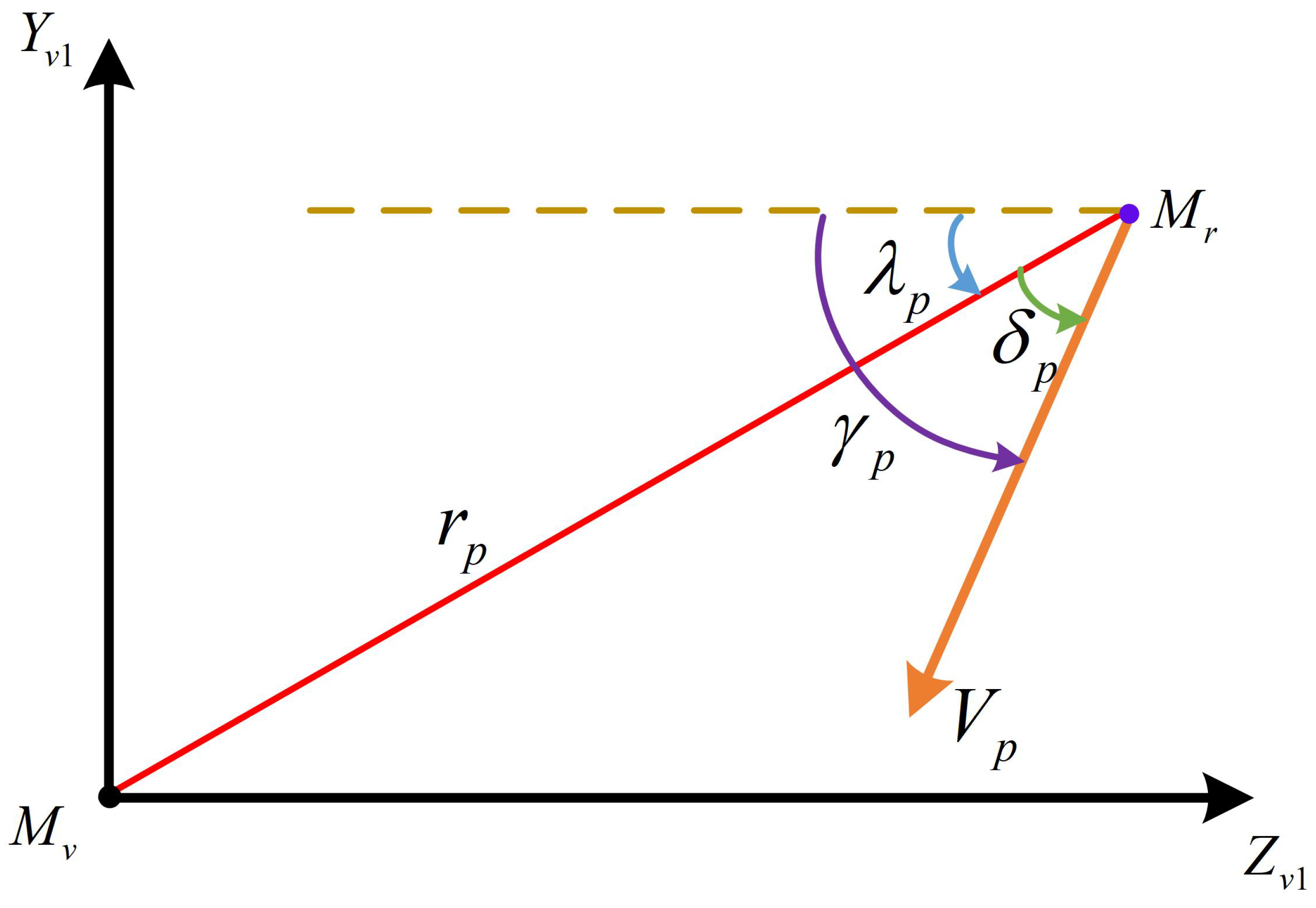
In the heading-normal plane( M v Y v 1 Z v 1 ) of the VCM, the motion relation of the UAV relative to the VCM is shown in Figure 2. The red line r p is the distance of the UAV relative to the VCM; the Orange arrow V p is the velocity of the UAV relative to the VCM; the blue arrow λ p is the LOS angle of the UAV relative to the VCM, and represents the angle between the UAV and the VCM and the M v Z v 1 axis; the green arrow δ p is the velocity leading angle of the UAV in the virtual ballistic system M v Y v 1 Z v 1 plane, and represents the angle between the velocity vector of the UAV in the course normal plane of the VCM and the connection between the UAV and the VCM; the purple arrow γ p is the velocity azimuth of the UAV in the M v Y v 1 Z v 1 plane of the virtual ballistic coordinate system, and represents the angle between the velocity vector and the M v Z v 1 axis of the UAV relative to the VCM.
The kinematic relationship between them is as follows:
z v = r p cos λ p y v = r p sin λ p z ˙ v = V p cos γ p y ˙ v = V p sin γ p γ ˙ p = a p V p
where y v , z v is the position vector of the UAV relative to the VCM in the M v Y v 1 Z v 1 plane of the virtual ballistic system.
The distance r p and LOS angle λ p of the UAV relative to the VCM meet the following relations:
r ˙ p = V p cos γ p λ p = V p cos δ p r p λ ˙ p = V p sin γ p λ p = V p sin δ p

3. Spiral Maneuvering Trajectory Design

3.1. Plane Relative Spiral Motion Design Based on Archimedes Spiral

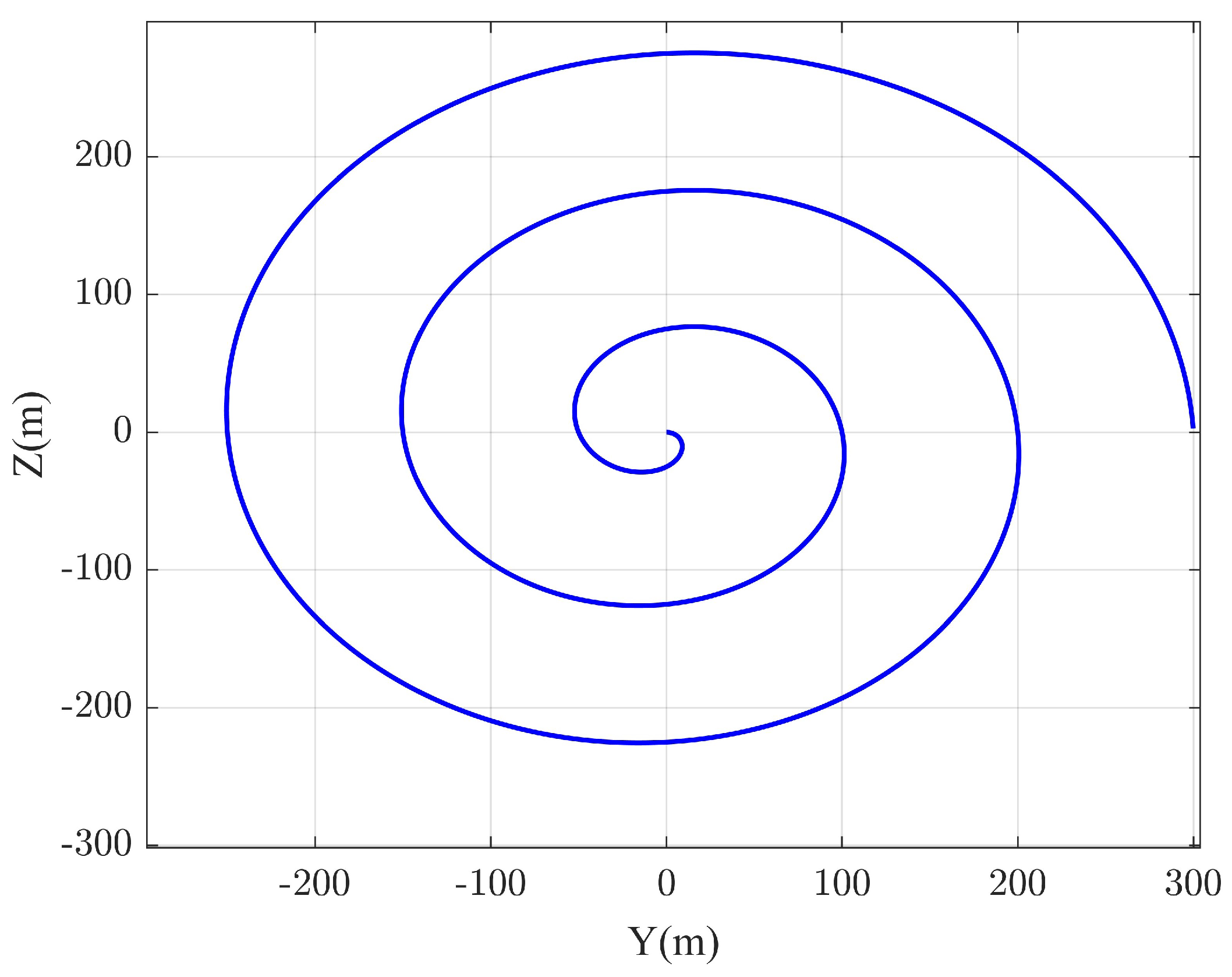
The plane relative spiral motion is designed with an Archimedes spiral, as shown in Figure 3.
The Archimedean spiral is canonically represented in polar coordinates by the following equation:
r = b θ b = d r d θ
where b denotes the pitch, defined as the radial displacement per unit angular increment θ . Here, θ corresponds to the angular displacement of the UAV relative to the VCM. The angular parameter θ , intrinsically governed by the number of spiral turns N, spans an unbounded domain θ ( , + ) , with the sign of N dictating the spiral’s chirality (clockwise or counterclockwise). This relationship is formalized as follows:
θ = λ p ξ p
where ξ p represents the terminal LOS angle between the UAV and VCM, which asymptotically defines the spiral’s endpoint orientation. Like θ , ξ p also spans [ , + ] . Given the initial radial distance r p 0 and LOS angle λ p 0 between the UAV and VCM, the pitch b is derived as follows:
b = r p 0 θ = r p 0 λ p 0 ξ p
The total number of spiral turns N t , determined by the initial and terminal LOS angles between the UAV and VCM, is expressed as follows:
N t = ( λ p 0 ξ p ) / 2 π
Combining Equations (8) and (9), the pitch simplifies to the following:
b = r p 0 2 π N t
Thus, the geometric configuration of the spiral is uniquely determined by the triad r p 0 , λ p 0 , N t , yielding the following radial trajectory:
r p = 2 π b N r
where N r = ( λ p ξ p ) / 2 π quantifies the remaining spiral turns.
To ensure the terminal guidance accuracy of the UAV, the relative spiral trajectory must asymptotically converge to the reference path generated by the VCM. This necessitates precise alignment between the UAV’s terminal position post-spiral and the VCM-derived reference trajectory. By imposing a uniform deceleration profile along the Archimedean spiral, the following kinematic system governs the motion:
V p 0 a c t g o = 0 V p 0 t g o 1 2 a c t g o 2 = S
where V p 0 denotes the initial relative spiral velocity, a c is the constant deceleration magnitude, t g o represents the maneuver duration and S quantifies the cumulative arc length traversed during t g o .
The arc length S λ p of an Archimedean spiral, as derived in [25], is expressed as follows:
S λ p = 1 2 b λ p ξ p 1 + λ p ξ p 2 + sinh 1 λ p ξ p
Substituting Equation (9) into Equation (13) yields the total spiral arc length:
S t = 1 2 b 2 π N t 1 + 2 π N t 2 + sinh 1 2 π N t
Synthesizing the total spiral maneuver duration t e n d with Equations (12) and (14), the initial relative spiral velocity V p 0 and deceleration a c can be analytically determined.
Two critical considerations warrant emphasis:
1.
The initial LOS angle between the UAV and VCM is conventionally initialized to λ p 0 = 0 , enabling maneuver amplitude and frequency to be modulated by adjusting the number of spiral turns N t and the initial radial distance r p 0 . Thus, the geometric configuration of the spiral is determined by the triad r p 0 , N t .
2.
The total spiral maneuver duration t e n d often deviates from the UAV’s actual flight time. To reconcile this discrepancy, t e n d is numerically optimized via the Newton–Raphson iterative method to satisfy terminal guidance precision for stationary targets. For mobile targets, the adjusted maneuver time t e n d Δ t is adopted, advancing convergence to the virtual trajectory to mitigate kinematic discrepancies induced by target motion, thereby ensuring terminal guidance precision.

3.2. Virtual Trajectory Generation Based on DRL

3.2.1. Reinforcement Learning Architecture

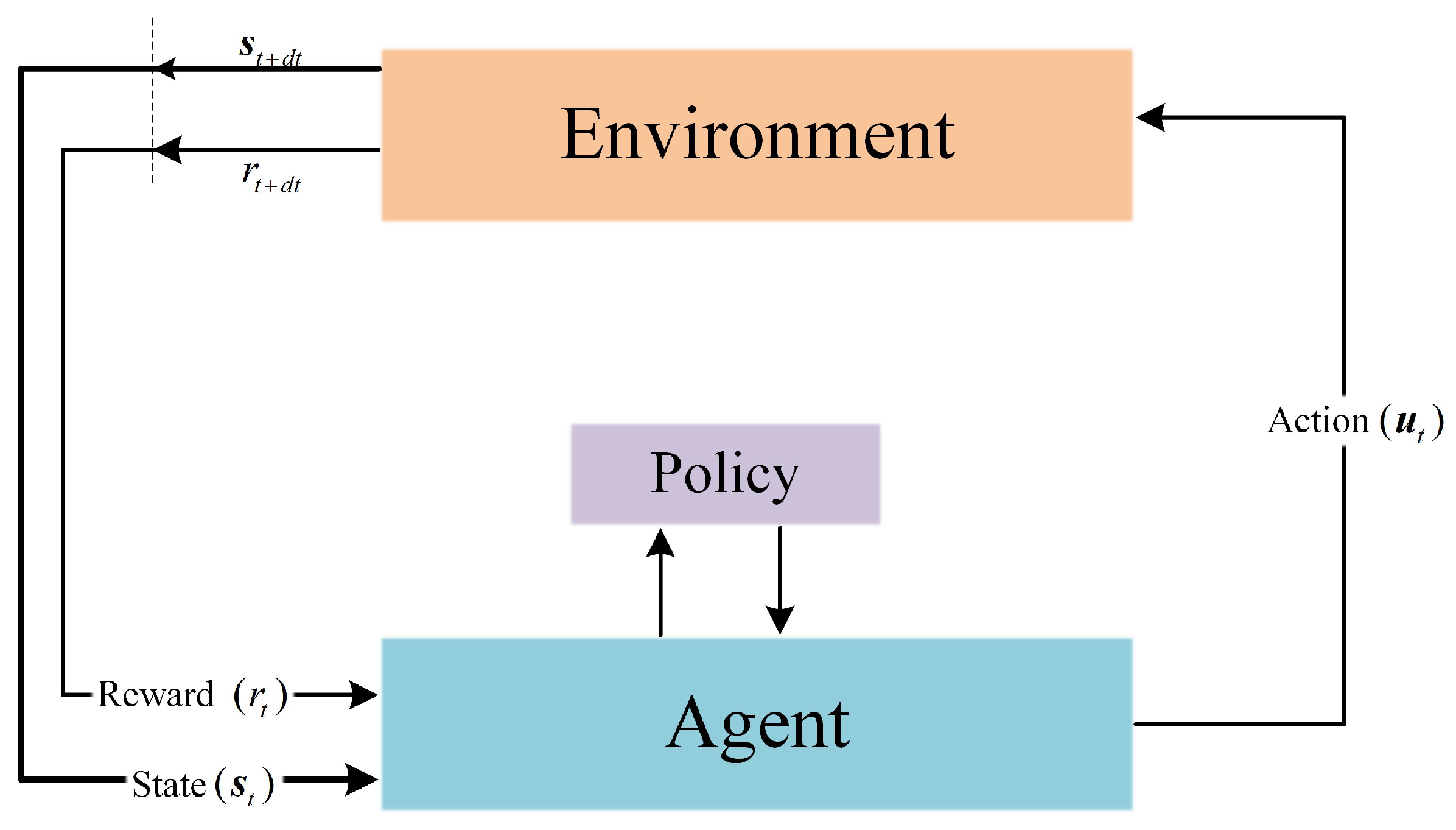
Within RL frameworks, agents iteratively engage with their operational environment through a trial-and-error learning paradigm to maximize cumulative reward signals in stochastic, high-dimensional state spaces. DRL integrates the perceptual capacities of deep neural networks with the decision-theoretic capabilities of RL, thereby enabling end-to-end autonomous decision-making systems. The interaction dynamics intrinsic to RL are formally modeled through a MDP, as illustrated in Figure 4, which establishes the foundational RL architecture. The algorithmic workflow proceeds as follows: (1) the agent observes the environmental state S t ; (2) the agent selects an action a t stochastically governed by the policy π ; (3) the environment transitions to a successor state S t + 1 through stochastic transitions; and (4) the agent computes the expected long-term discounted return based on the scalar reward r t , subsequently refining the policy π via gradient-based optimization.
In RL, the reward function serves as a critical mechanism for facilitating policy optimization, being intrinsically linked to the environmental state s t and the agent’s selected action a t , mathematically formulated as r t s t , a t . A trajectory τ is formally defined as the state–action sequence generated through the agent’s iterative interactions under policy π , expressed as τ = s 0 , a 0 , s 1 , a 1 , . The return function R τ , representing the cumulative discounted reward over the trajectory, is rigorously formalized in Equation (15), encapsulating the agent’s long-term strategic objective.
R ( τ ) = t = 0 T γ t r t
where t denotes the temporal decision index, T represents the terminal decision horizon, and γ 0 , 1 defines the discount factor modulating the temporal weighting between immediate and deferred rewards. The principal objective of RL revolves around the maximization of the expected cumulative return, where the optimal policy π * is derived through the following optimization framework:
π * = arg max π E τ π R τ
RL incorporates state- and action-value functions as quantitative metrics for policy evaluation and serves as the foundation for policy optimization. The state-value function V π s , representing the expected cumulative discounted return when the agent executes policy π from state s , is mathematically formalized as follows:
V π s = . E τ t π R τ t s t = s
where s t denotes the state vector at time step t, and τ t represents a trajectory generated under policy π .
Similarly, the action-value function Q π s , a , which estimates the expected cumulative return for executing action a in state s under policy π , is formalized as follows:
Q π s , a = . E τ t π R τ t s t = s , a t = a
where a t corresponds to the action taken at time step t.
These functions provide foundational guidance for the agent’s iterative policy improvement, directing convergence toward optimality. In DRL, parametric approximations of V π s and Q π s , a are typically achieved through deep neural networks, enabling scalable representation of value functions in high-dimensional state–action spaces.
In RL, the absolute utility of an agent’s actions is often secondary to their relative efficacy compared to alternative actions. This distinction underpins the pivotal role of the advantage function, a foundational construct in RL that quantifies the relative merit of an action a in state s under policy π . Formally, the advantage function is defined as follows:
A π s , a = Q π s , a V π s
To estimate A π s , a , the generalized advantage estimation (GAE) method [26] serves as a prevalent estimator in policy optimization frameworks. The GAE is expressed as follows:
A π , t GAE s , a = l = 0 γ λ l δ t + l V
where δ t V represents the temporal difference (TD) residual:
δ t V = r t + γ V π s t + 1 V π s t
where γ [ 0 , 1 ] and λ [ 0 , 1 ] are hyperparameters governing the discount factor and bias–variance trade-off, respectively. The GAE framework integrates multi-step returns, enabling stable and efficient credit assignment across trajectories.

3.2.2. Interactive Scene

The design of the interactive engagement environment must be predicated on the operational scenario, adversarial kinematic constraints and comprehensive inclusion of potential agent states.
(1)
Target State Initialization
In scenarios involving UAV engagement with slowly maneuvering targets, it is postulated that, during target acquisition, the target initiates rectilinear motion within the horizontal plane. The target’s velocity magnitude V t and heading angle ψ t are modeled as uniformly distributed variables: ψ t U ( π , π ) , V t U ( 0 , 15 ) m / s .
(2)
VCM State Initialization
The initial position and velocity of the VCM are derived computationally from the UAV’s relative spiral motion parameters and initial state. The kinematic relationship between the UAV and VCM is governed by the following:
V v = V r V p
where V v , V r and V p denote the VCM’s inertial velocity, UAV’s inertial velocity and UAV’s velocity relative to the VCM, respectively.
At initialization ( t = 0 ),
V v x 0 , V v y 0 , V v z 0 T = V r x 0 , V r y 0 , V r z 0 T V p x 0 , V p y 0 , V p z 0 T
where V v x 0 , V v y 0 , V v z 0 T is the velocity vector of the VCM under the inertial coordinate system at the initial moment; V r x 0 , V r y 0 , V r z 0 T is the velocity vector of the vehicle in the inertial coordinate system at the initial moment; V p x 0 , V p y 0 , V p z 0 T is the velocity vector of the UAV relative to the VCM at the initial moment, and its specific expression is as follows:
V p x 0 , V p y 0 , V p z 0 T = 0 , V p 0 sin γ p 0 , V p 0 cos γ p 0 T
where γ p 0 is the velocity azimuth of the UAV in the heading-normal plane of the VCM at the initial moment.
Substituting Equations (4), (6) and (7) yields:
tan δ p = λ p ξ p
And γ p , λ p and δ p have the following relationship:
γ p = δ p + λ p
By substituting λ p 0 into Equations (25) and (26), the initial velocity of the VCM under the inertial coordinate system can be calculated. Then according to Equations (23) and (24) we can calculate γ v 0 and ψ v 0 .
The UAV’s initial position within the VCM’s heading-normal plane facilitates determination of the VCM’s inertial position via the following:
x v 0 , y v 0 , z v 0 T = x r 0 , y r 0 , z r 0 T L ψ v 0 , γ v 0 x r 0 , y r 0 , z r 0 T
where [ x v 0 , y v 0 , z v 0 ] T and x r 0 , y r 0 , z r 0 T are the positions of the VCM and the UAV in the inertial coordinate system at the initial moment, respectively; L ψ v 0 , γ v 0 is the transformation matrix from the inertial coordinate system to the virtual ballistic coordinate system.
(3)
VCM Velocity Compensation
The fundamental requirement for generating a stable spiral maneuvering trajectory is that the UAV maintains motion within the course-normal plane of the VCM. However, since the trajectory design methodology employs a bank-to-turn (BTT) control architecture, the UAV cannot inherently constrain its positional component along the X-axis of the virtual ballistic coordinate system to null. To address this limitation, a velocity compensation mechanism is applied to the VCM, ensuring persistent alignment of the UAV with the VCM’s course-normal plane. The compensated velocity vector is governed by the following:
V v e = K e Δ x e + V x d
where V v e denotes the compensated VCM velocity; Δ x e represents the UAV’s positional deviation along the M v X v 1 -axis of the virtual ballistic coordinate system; V x d corresponds to the UAV’s velocity component along the M v X v 1 -axis; K e is the feedback gain coefficient, and takes 20 in the simulation.

3.2.3. MDP for Virtual Trajectory Generation

The efficacy of RL in UAV trajectory synthesis hinges on the rigorous formulation of a MDP, encompassing the definition of a state space, action space and reward function that holistically encapsulate system dynamics and control objectives.
(1)
State Space and Action Space Design
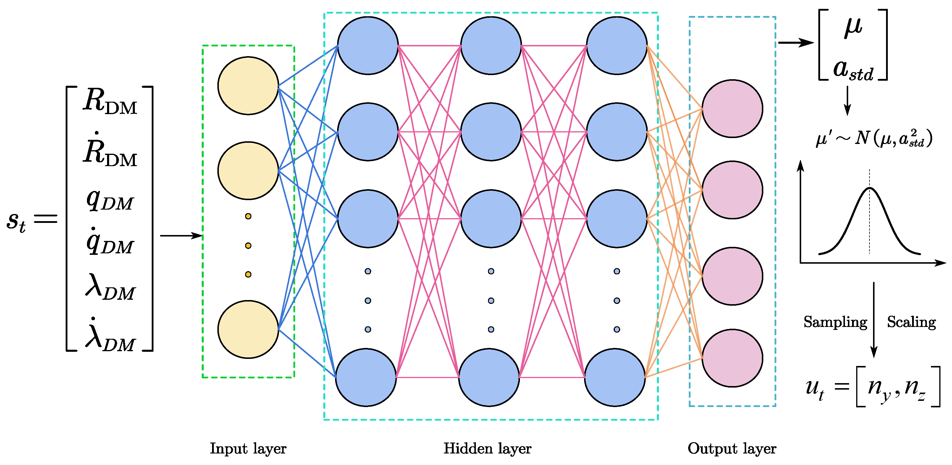
The state space is architected to emulate the perceptual constraints of onboard sensor systems, such as radar-based seekers, which provide measurements of relative kinematics and angular geometries. To approximate real-world operational fidelity, the state vector s t integrates six degrees of freedom derived from the VCM–target engagement dynamics:
s t = R DM , R ˙ DM , q D M , q ˙ D M , λ D M , λ ˙ D M T
where R DM is the relative range between the VCM and target; R ˙ DM is the relative range rate between the VCM and the target; q D M and q ˙ D M are the LOS elevation angle and LOS elevation angle rate between the VCM and the target; λ D M and λ ˙ D M are the LOS azimuth angle and LOS azimuth angle rate between the VCM and the target.
The action space governs the VCM’s maneuverability through normalized lateral acceleration commands, bounded by operational limits to reflect actuator saturation:
u t = n y n max , n max n z n max , n max
where n y and n z denote lateral acceleration components in the pitch and yaw axes, respectively, and n max defines the maximum achievable g-load.
(2)
Reward Function Architecture
The reward function constitutes a pivotal mechanism in DRL, critically influencing policy convergence and optimality. Its design must holistically encode the mission’s kinematic objectives to ensure higher rewards correlate with trajectories satisfying terminal precision.
The real missile moves in a relative spiral around the virtual trajectory until it converges to the virtual trajectory. Its relative spiral motion provides powerful penetration capability, while the virtual trajectory needs to provide a high-precision strike effect. Therefore, the reward function is designed into the following two parts:
r t = r s + r e
where r s and r e are the process reward and terminal reward, respectively. The specific expressions for r s and r e are as follows:
r s = k s exp [ [ ( q ˙ D M ) 2 + ( λ ˙ D M ) 2 ] / 0.05 ]
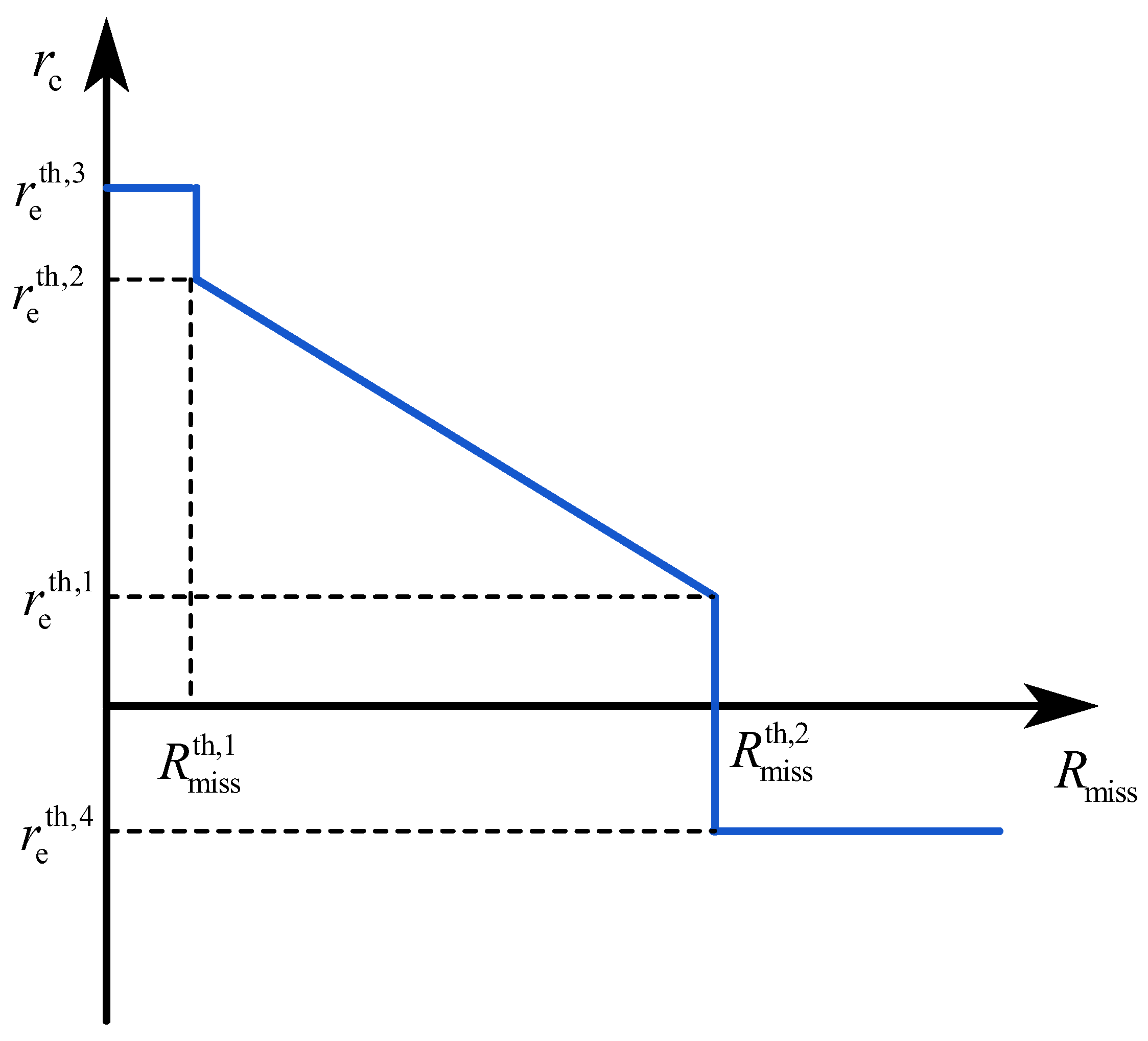
r e = R miss R miss th , 1 R miss th , 2 R miss th , 1 r e th , 2 r e th , 1 + r e th , 1 , R miss th , 1 R miss R miss th , 2 r e th , 3 , R miss R miss th , 1 r e th , 4 , R miss > R miss th , 2
where r s is designed according to the principle of the classical guidance law to achieve a quasi-parallel approach by restraining the angular speed of the missile eye. This reward is conducive to promoting the agent to generate the instruction to fly towards the target. r e is a reward that reflects the miss distance of the terminal, and gives a large positive reward when the interception is successful; k s is a hyperparameter greater than 0; R miss is the miss distance; R miss th , 1 and R miss th , 2 are hyperparameters related to the miss distance, where R miss th , 1 represents the miss distance corresponding to the successful interception of the target; r e th , 1 , r e th , 2 , r e th , 3 and r e th , 4 are hyperparameters related to the reward; the diagram of r e is shown in Figure 5.

3.2.4. Model Solving Based on PPO Algorithm

The PPO algorithm demonstrates superior performance in high-dimensional continuous control tasks and has been established as the de facto standard for policy gradient methods in autonomous guidance systems, as endorsed by OpenAI. Consequently, this work adopts PPO as the foundational algorithm for virtual trajectory synthesis. A concise overview of PPO is provided below; comprehensive theoretical derivations are detailed in Ref. [27].
PPO manifests in two primary variants: (1) adaptive KL divergence-penalized policy optimization (PPO-KL) and (2) clipped surrogate objective optimization (PPO-CLIP). While both variants achieve a comparable empirical performance, PPO-CLIP is computationally advantageous, as it circumvents the necessity for iterative KL divergence calculations. This work employs the PPO-CLIP formulation for its operational efficiency.
The PPO-CLIP framework integrates dual neural networks—a policy network π θ and a value network V ω —to maximize the composite objective function:
L PPO ( θ , ω ) = E L CLIP ( θ ) c VF L VF ( ω ) + c s L H ( θ )
where c VF and c s are hyperparameters; θ and ω represent the parameters of policy network and value network, respectively. L CLIP ( θ ) is the optimization target of the policy network, which can be calculated by Equation (35). L VF ( ω ) is the optimization target of the value network, which can be calculated by Equation (37). L H θ = E a π θ log π θ a s is the entropy of the policy, reflecting the uncertainty of the policy.
L CLIP θ = E s , a π θ , old min p θ A π θ , old GAE s , a , clip p θ , 1 ε , 1 + ε A π θ , old GAE s , a
where π θ and π θ , old represent the new policy and the old policy, respectively; p θ = π θ a s π θ a s π θ , old a s π θ , old a s represents the probability ratio corresponding to the old and new strategies; clip ( · , · , · ) is the clipping function, which can be expressed as follows:
clip ( p ( θ ) , 1 ε , 1 + ε ) = 1 ε , p ( θ ) < 1 ε p ( θ ) , 1 ε p ( θ ) 1 + ε 1 + ε , p ( θ ) > 1 + ε
where E is a small hyperparameter, which is used to ensure that there is not much difference between the old and new policies.
L VF ( ω ) = V π θ ( s ; ω ) V π θ , old targ ( s ; ω ) 2
where V π θ , old t arg ( s ; ω ) is the target of the value network; the calculation formula is as follows:
V π θ , old targ ( s ; ω ) = A π θ , old GAE ( s , a ) + V π θ , old s ; ω old
The technique of reward scaling [28] is introduced to avoid the negative impact of too large or too small rewards on the learning of the value network, which can be expressed as the goal of the scaled value network:
V ˜ π θ , old targ ( s ; ω ) = V π θ , old targ ( s ; ω ) σ V targ
where σ V targ g is the standard deviation of all V π θ , old targ ( s ; ω ) .
At the same time, in order to improve the stability of the training process, the gradient clipping technique [28] is introduced to solve the gradient g θ of θ and the gradient g ω of ω :
g θ = min g max / θ L PPO ( θ , ω ) , 1.0 · θ L PPO ( θ , ω ) g ω = min g max / ω L PPO ( θ , ω ) , 1.0 · ω L PPO ( θ , ω )
where g max is the gradient clipping value.
To update the parameters of the policy network and the value network, the objective function given by the Adam optimizer maximization (Equation (35)) is adopted:
θ θ + α 1 r g θ ω ω + β lr g ω
where α lr and β lr are the learning rates of the strategy network and value network, respectively.
Further, decaying learning rates enhance late-stage training stability:
α lr = α lr , 0 1 t e / N epoch β lr = β lr , 0 1 t e / N epoch
where a l p h a lr , 0 and β lr , 0 are the initial learning rates of the strategy network and value network, respectively; t e is the current training algebra; N epoch is the maximum training algebra.

3.2.5. Network Structure Design

The policy network architecture (Figure 6) implements a bidirectional Gaussian policy parameterization, comprising four output neurons: two-dimensional mean μ and standard deviation σ s t d vectors that parameterize the stochastic action distribution. During the training phase, actions are stochastically sampled from the Gaussian distribution N μ , σ s t d 2 , followed by a nonlinear transformation via hyperbolic tangent (tanh) activation and affine scaling to enforce bounded action spaces.
The architectural specifications of the PPO policy and value networks—comprising layer-wise neuron counts and associated activation functions—are formally delineated in Table 2 to provide a comprehensive structural overview of the proposed framework.

3.2.6. Learning Process

As derived from the preceding analytical framework, the learning-driven methodology for autonomous virtual trajectory synthesis, leveraging the PPO-CLIP algorithm, is formalized in Algorithm 1.
Algorithm 1 Learning process
  • Initialization: Policy network with parameter θ , behavioral policy network θ old θ , value network with parameter ω , reward related hyperparameters k s , r e th , 1 , r e th , 2 , r e th , 3 , r e th , 4 , R miss th , 1 and R miss th , 2 , GAE hyperparameter λ , discount factor γ , value network error weight factor c VF , entropy weight factor c s of policy, clipping factor ε , initial learning rate α lr , 0 and β lr , 0 of strategy network and value network, maximum training algebra N epoch , number of network parameter updates per training N update , number of tracks rollout N rollout , experience pool size D , batch transfer data size B , gradient clipping threshold g max , interactive environment boundary parameters.
1:
for  t e = 1 , 2 , , N epoch do
2:
     Using rollouts to take π θ old as the behavior strategy, the network interacts with the
        environment to generate N rollout tracks, which are stored in the experience pool
         D = T 1 , T 2 , , T N collect , where D is a collection of tuples s t , a t , r t , s t + 1 .
3:
     Compute the dominance function A π θ , old GAE according to Equation (20) and update the
        tuple in D to s t , a t , r t , s t + 1 , A π θ , old , t GAE .
4:
     Calculate the objective value function V π θ , old targ according to Equation (38) and update
        the tuple in D to s t , a t , r t , s t + 1 , A π θ , old , t GAE , V π θ , old , t targ .
5:
     for  i = 1 , , N update  do
6:
           Batch transfer data B is obtained by random sampling from experience pool D ,
           and calculate PPO objective function:
            L PPO ( θ , ω ) = 1 | B | B min p π θ , π θ , old A π θ , ld GAE , clip p π θ , π θ , old , 1 ε , 1 + ε A π θ , old GAE c VF V π θ ( s ; ω ) V π θ , ldt targ ( s ; ω ) 2 c s log π θ a t s t
7:
           Calculate the cropped gradients x and x according to Equation (40).
8:
           Update network parameters according to Equation (41).
9:
     end for
10:
    Clear D .
11:
    Update the behavior policy network parameter θ old θ .
12:
    Update the learning rate according to Equation (42).
13:
end for

3.3. Spiral Maneuvering Trajectory Generation

The relative spiral motion is attached to the virtual trajectory to form a spiral maneuver trajectory, as shown in Figure 7.
The position and velocity of the UAV in the virtual ballistic coordinate system are as follows:
x d v , y d v , z d v T = 0 , r p sin λ p , r p cos λ p T
x ˙ d v , y ˙ d v , z ˙ d v T = 0 , V p sin γ p , V p cos γ p T
where [ x r , y r , z r ] T and x v , y v , z v T are the position and velocity of the UAV in the virtual ballistic coordinate system; V p is the velocity of the vehicle relative to the VCM.
At every moment, r p can be obtained by Equation (11), λ p can be obtained by Equation (13), and γ p can be obtained by Equations (25) and (26). By substituting r p , λ p and γ p into Equations (43) and (44), the position and velocity of the UAV in the virtual ballistic coordinate system can be obtained, and the position and velocity of the UAV in the inertial coordinate system can be calculated:
x r , y r , z r T = L ψ v , γ v T L ψ v , γ v x v , y v , z v T + x d v , y d v , z d v T
V x d , V y d , V s d T = L ψ v , γ v T x ˙ d v , y ˙ d v , z ˙ d v T
where [ x r , y r , z r ] T and x v , y v , z v T are the positions of the UAV and the VCM in the inertial coordinate system; V x d , V y d , V z d T is the velocity of the UAV in the inertial coordinate system; L ψ v , γ v T is the transformation matrix from virtual ballistic coordinate system to inertial coordinate system.
Under dynamic target engagement scenarios, the empirically predetermined spiral maneuver duration is configured to be shorter than the UAV’s actual flight duration to account for adversarial motion. As prescribed by the proposed methodology, upon reaching the designated spiral maneuver interval, the UAV achieves kinematic congruence (position and velocity vector alignment) with the VCM. This synchronization enables a seamless transition to subsequent trajectory synthesis through persistent VCM-based guidance laws, thereby maintaining terminal guidance phase precision for high-fidelity target engagement.

4. Simulation Analysis

This section conducts numerical simulations to systematically evaluate the feasibility and operational efficacy of the proposed DRL-enabled framework for the online synthesis of spiral maneuvering trajectories. Initially, a robust policy network is trained through hyperparameter optimization to achieve convergence in adversarial engagement scenarios. Subsequently, statistical Monte Carlo simulations are executed to quantify terminal precision and analyze the UAV’s state-space evolution under dynamic target kinematics.
The UAV’s parametric configuration, including inertial properties and aerodynamic coefficients, is adopted from the benchmark model in Ref. [29]. The simulation parameters are shown in Table 3.

4.1. Training Process

The training and validation simulations presented in this study were conducted using a Python 3.11 computational framework integrated with the PyTorch 2.5.1 deep learning library. The hardware configuration comprised an Intel® Core™ i5-12600KF central processing unit (CPU) operating at 3.70 GHz, an NVIDIA GeForce RTX 3060 graphics processing unit (GPU), 16 GB of random-access memory (RAM) and a 64-bit operating system to ensure sufficient computational throughput for policy-gradient optimization. Critical hyperparameters governing the PPO algorithm, including learning rate, discount factor, clipping threshold and the reward function architecture, are systematically tabulated in Table 4 to ensure reproducibility and methodological transparency.
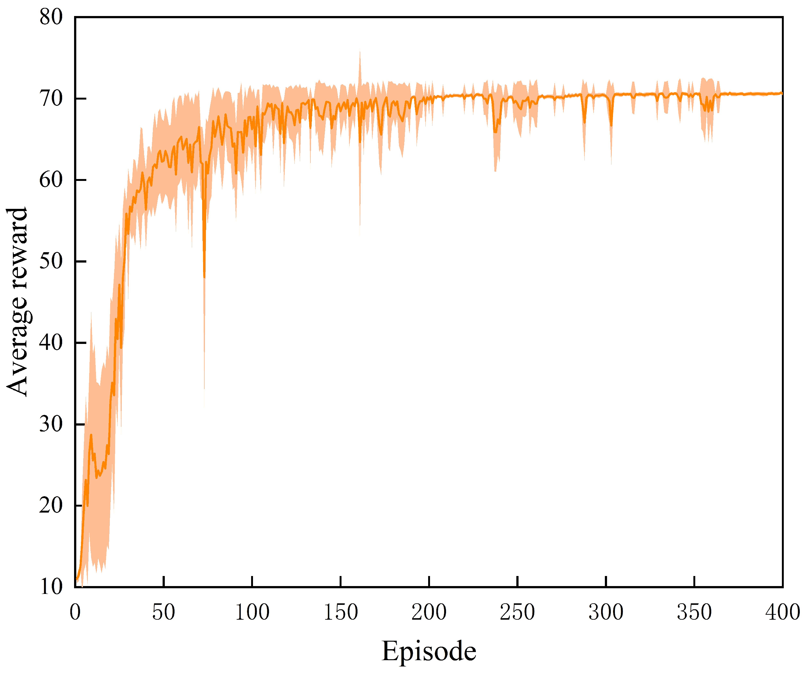
The procedural workflow for synthesizing virtual trajectories through DRL training, employing the PPO algorithm, is delineated in Figure 8. This visualization quantifies the temporal evolution of the mean reward trajectory across training episodes, thereby characterizing the convergence dynamics of the DRL framework. The exponentially weighted moving average (EMA) of episodic rewards is represented by the solid line, while the shaded region quantifies the dispersion (standard deviation) of the reward distribution across policy iterations. This dispersion metric serves as a robustness indicator, reflecting the stability and stochastic variance inherent to the policy gradient optimization process.
Initial Phase (Episodes 0–50): The mean reward exhibits a rapid monotonic increase from near-zero baseline values, signifying that the agent has developed foundational policy efficacy through exploratory interactions with the environment. Concurrently, the significant stochastic variance (evidenced by the broad confidence interval) reflects high entropy in the initial policy distribution and unconstrained exploration dynamics.
Intermediate Phase (Episodes 50–250): A diminished yet sustained positive gradient in reward accumulation is observed, accompanied by progressive contraction of the reward distribution’s dispersion. This dual trend indicates stabilization of the policy’s action-value estimates and an improved exploitation–exploration trade-off. The agent transitions from stochastic exploration toward deterministic policy dominance, attenuating noise-induced perturbations in the optimization landscape.
Convergence Phase (Episodes 250–400): The reward metric asymptotically approaches steady-state values with minimal episodic fluctuations, while the standard deviation converges to a lower-bound threshold. These dynamics confirm algorithmic convergence, with policy invariance across training batches and bounded susceptibility to environmental stochasticity, thereby validating the robustness of the optimized control strategy.

4.2. Test Process

In order to verify the validity and feasibility of the method proposed in this paper, the agent trained by PPO algorithm is used to generate a virtual trajectory, and the relative spiral is attached to the virtual trajectory. Two parts of simulation test are designed. The first part verifies that the spiral trajectory in this paper is adjustable and adopts different spiral parameters to strike fixed targets. In the second part, the accuracy of attacking moving targets is verified. A Monte Carlo simulation is carried out for targets with different moving directions and different moving speeds using a set of spiral parameters.

4.2.1. Different Spiral Parameters

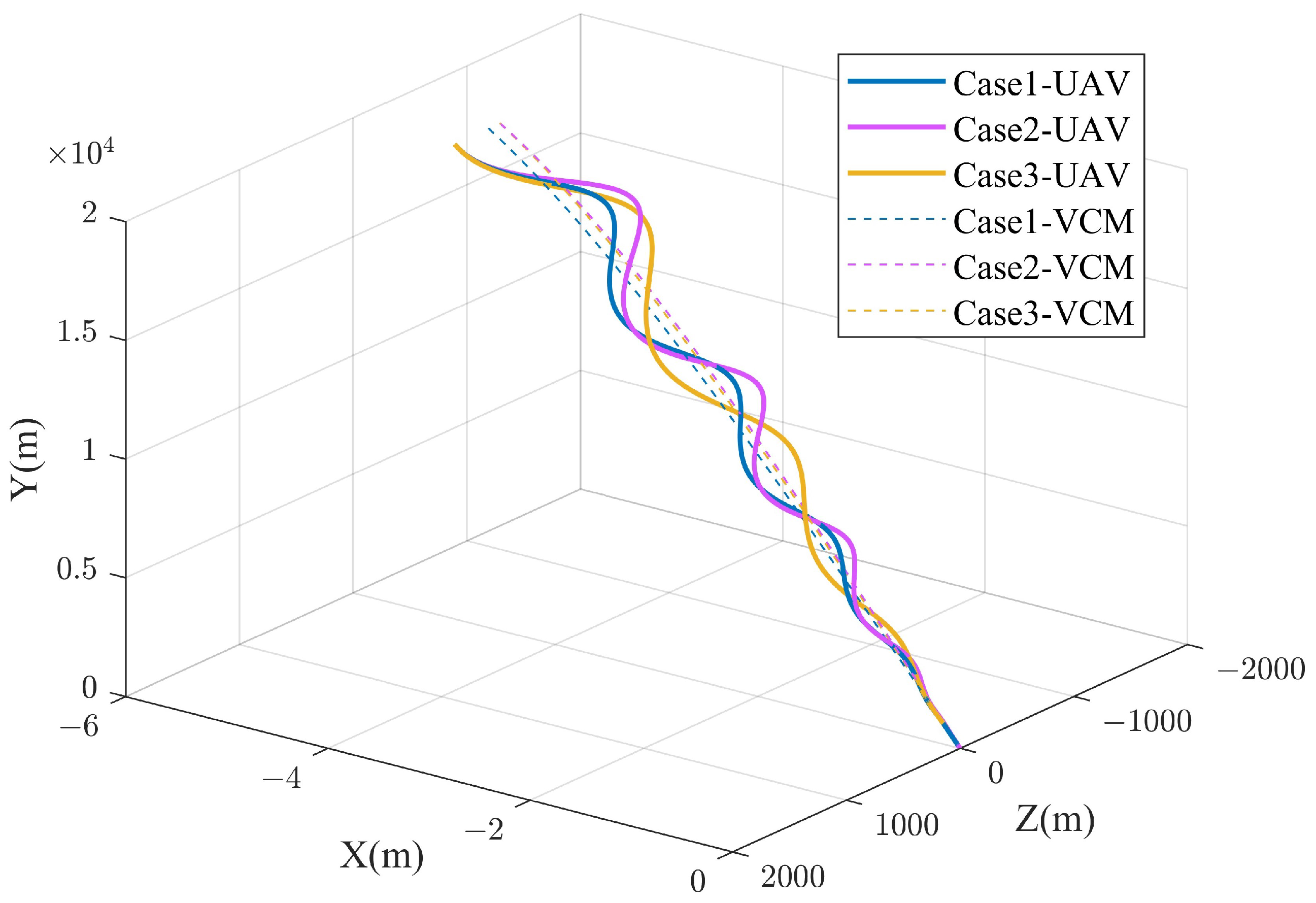
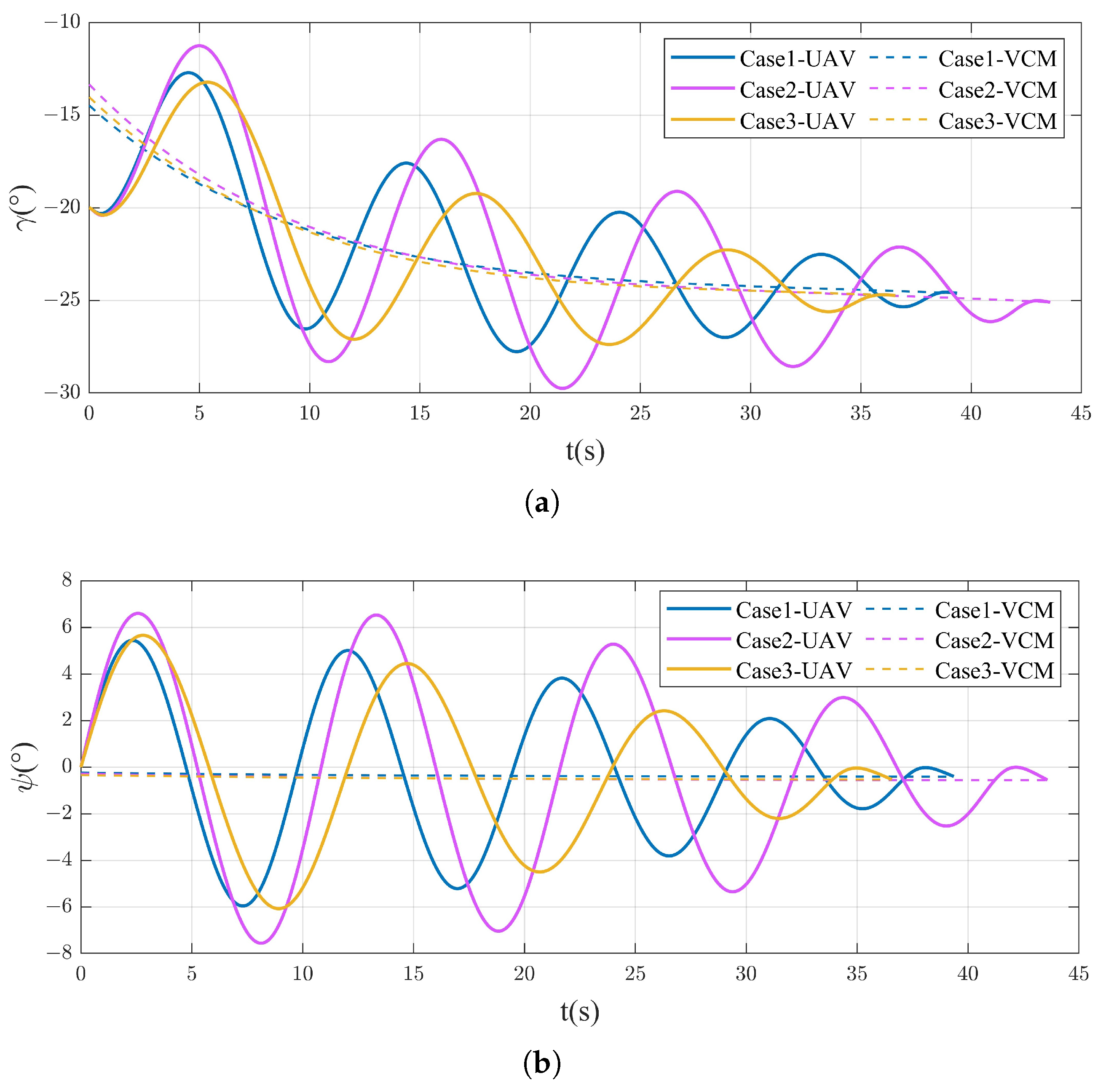
To empirically validate the parametric adjustability of the proposed spiral trajectory framework, three distinct parametric configurations were systematically configured for terminal engagement with stationary targets. Case 1: r p 0 = 300 m , N t = 4.0 cycles; Case 2: r p 0 = 400 m , N t = 4.0 cycles; Case 3: r p 0 = 400 m , N t = 3.0 cycles.
Within this experimental configuration, Cases 1 and 2 exhibit parametric divergence exclusively in the number of spiral turns, thereby enabling the isolation and quantitative evaluation of turn-frequency effects under a constant initial spiral radius. Conversely, Cases 2 and 3 maintain identical N t values while varying r p 0 , creating a controlled basis for analyzing radius-dependent trajectory modulation.
Figure 9 delineates the three-dimensional virtual trajectory and spiral maneuvering trajectories generated under the three parametric configurations. Divergence in virtual trajectory geometry arises from the computational derivation of the VCM position and velocity vectors, which are parameterized by the UAV’s initial kinematic state (position, velocity) and the spiral trajectory coefficients. This dependency cascades into heterogeneous initial conditions for the VCM, thereby inducing case-specific trajectory variance. Furthermore, parametric variations in spiral geometry—specifically, radius( r p 0 ) and angular frequency( N t )—yield distinct spatial maneuver characteristics.
Figure 10 illustrates the velocity slope angle and velocity azimuth profiles for both the UAV and the VCM. The figure reveal that the UAV’s velocity slope angle and velocity azimuth exhibit periodic oscillations around the corresponding VCM parameters, with amplitudes diminishing asymptotically until convergence is achieved. This trajectory stabilization enables high-precision strike capabilities. A comparative analysis of Cases 1–3 demonstrates that the UAV in Case 2 undergoes markedly larger angular variation amplitudes in both velocity slope angle and velocity azimuth relative to the VCM. These observations confirm a proportional relationship between spiral parameter( r p 0 , N t ) enlargement and elevated maneuvering intensity.
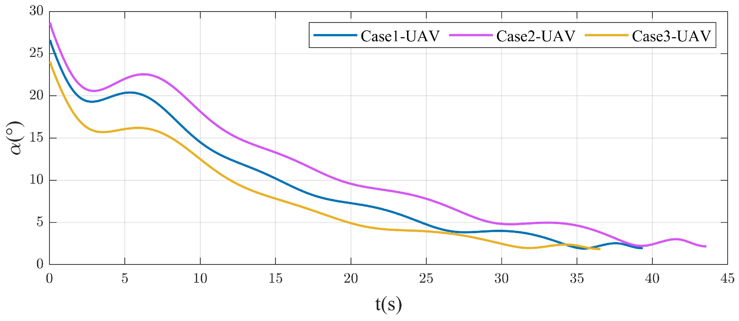
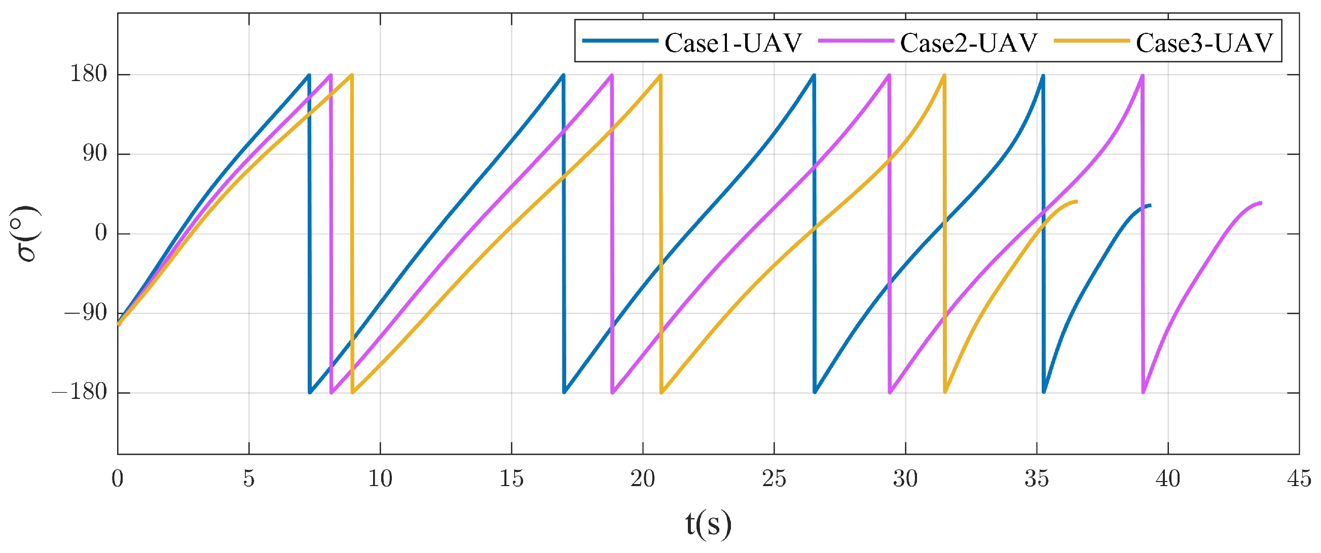
Figure 11 and Figure 12 show the changes in the attack angle and the bank angle during flight. Figure 11 shows the change curve of the attack angle. The control method adopted in this paper is BTT control, and the magnitude of the attack angle will directly affect the lift force. Due to the high altitude at the initial moment, the atmosphere is relatively thin at this time, so a large attack angle is required to provide enough lift for maneuvering. As the altitude gradually decreases and the atmosphere becomes denser, and based on the maneuver design of an Archimedean spiral, the lift required for subsequent maneuvers also gradually decreases, so the required attack angle also shows a gradually decreasing trend. Figure 12 shows the change curve of the bank angle. The bank angle breaks down the lift force of the UAV into lateral and normal upward to achieve spiral maneuvering around the virtual trajectory. In addition, this paper considers that the UAV can achieve 180° rollover, and the bank angle of the UAV also presents periodic changes according to the design principle of relative spiral motion.
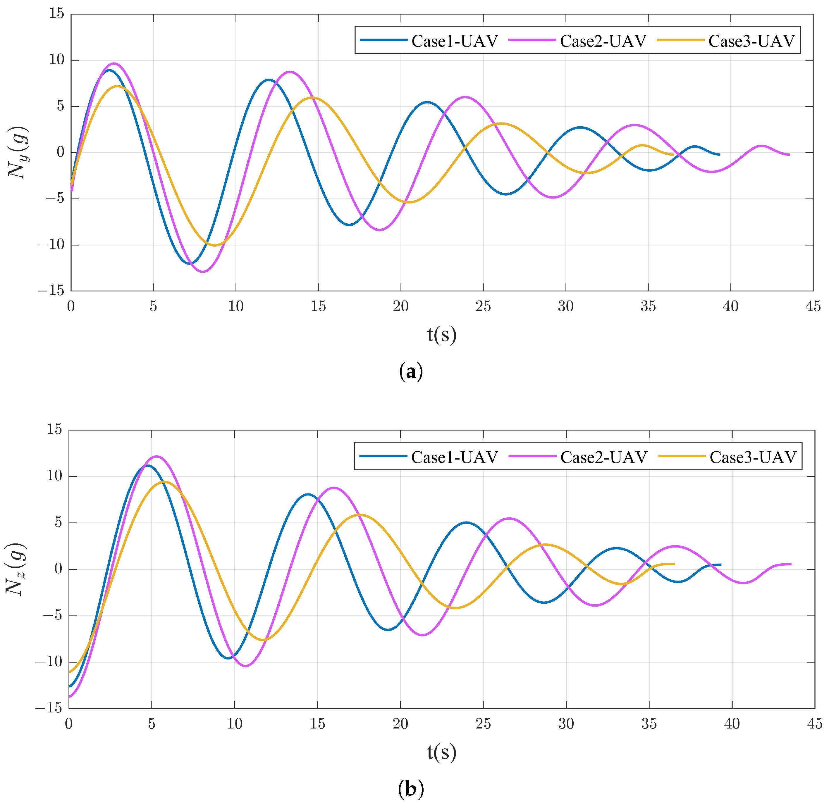
Figure 13 shows the variation in the UAV overload over time. As evidenced in Figure 13a,b, both lateral and normal overload exhibit oscillatory dynamics with progressive amplitude attenuation. The reason for the up and down fluctuation of the transverse normal overload is that the design of the spiral maneuvering trajectory based on the Archimedean spiral is to carry out relative spiral motion around the virtual trajectory for many revolutions; the reason for the gradual reduction and convergence of the required overload is that the UAV carries out the relative spiral motion is a uniformly decelerating motion, and the reduction of the speed leads to a gradual reduction in the overload required to achieve the change of the speed direction. A comparative analysis of Cases 1–3 reveals that the UAV in Case 2 necessitates significantly higher lateral and normal overloads. This observation suggests an enlarged spiral radius and turns requiring enhanced overload to achieve.
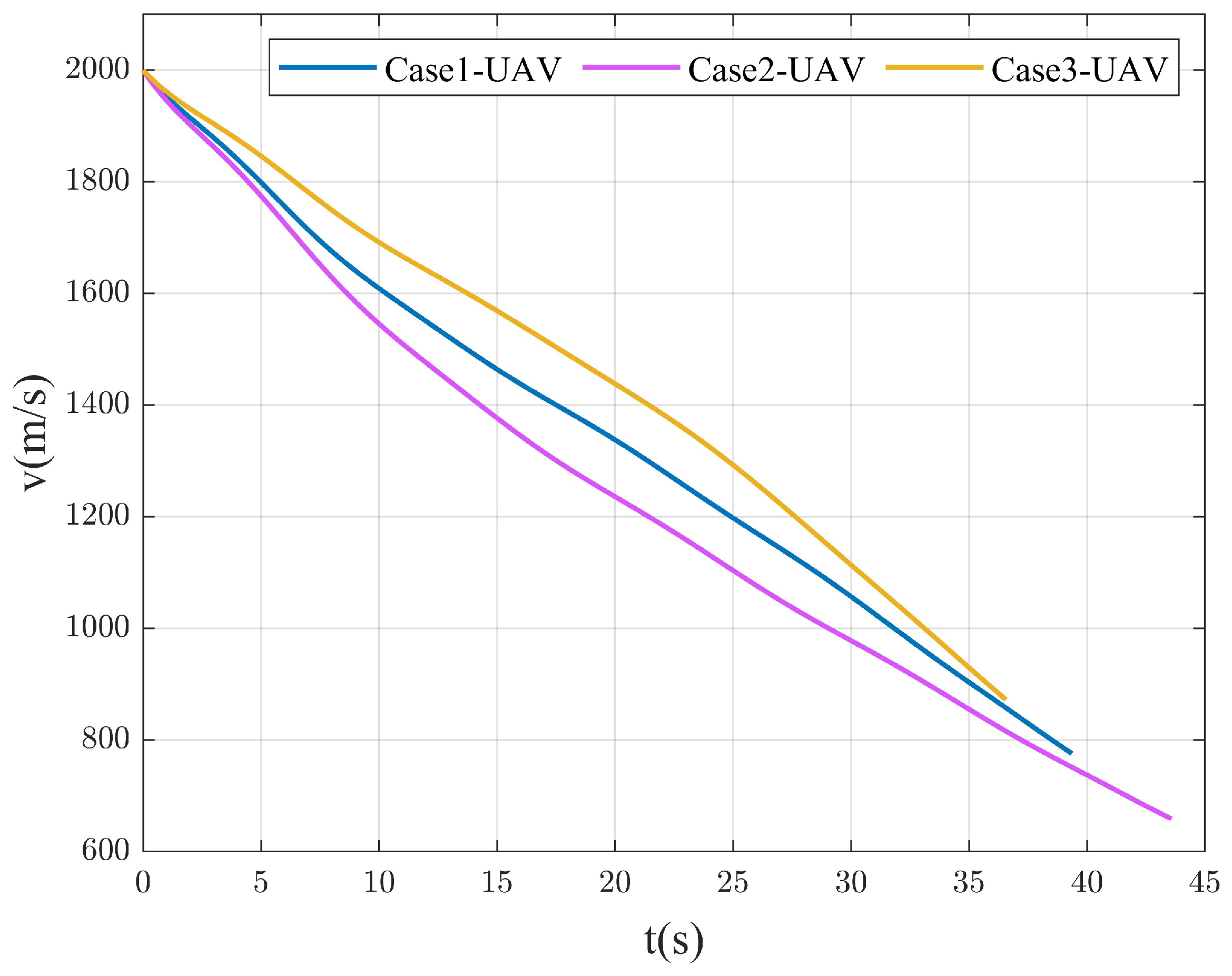
The temporal evolution of the UAV’s velocity profile is delineated in Figure 14. The speed of the UAV gradually decreases from the initial 2000 m/s, Case 1 to 779.91 m/s, Case 2 to 669.17 m/s and Case 3 to 878.70 m/s. Empirical analysis reveals a positive correlation between the spiral trajectory parameters and the final falling speed: the larger the spiral radius and the more spiral turns, the longer the flight time of the UAV, and the slower the final falling speed.

4.2.2. Attack Moving Target

To verify the accuracy of the proposed method in attacking moving targets, 500 Monte Carlo simulations were carried out. The spiral parameters are Case 2 in the previous section and the adjusted maneuvering time Δ t = 3 s. The moving speed of the target V t U ( 0 , 15 ) m/s and the moving direction ψ t U ( π , π ) .
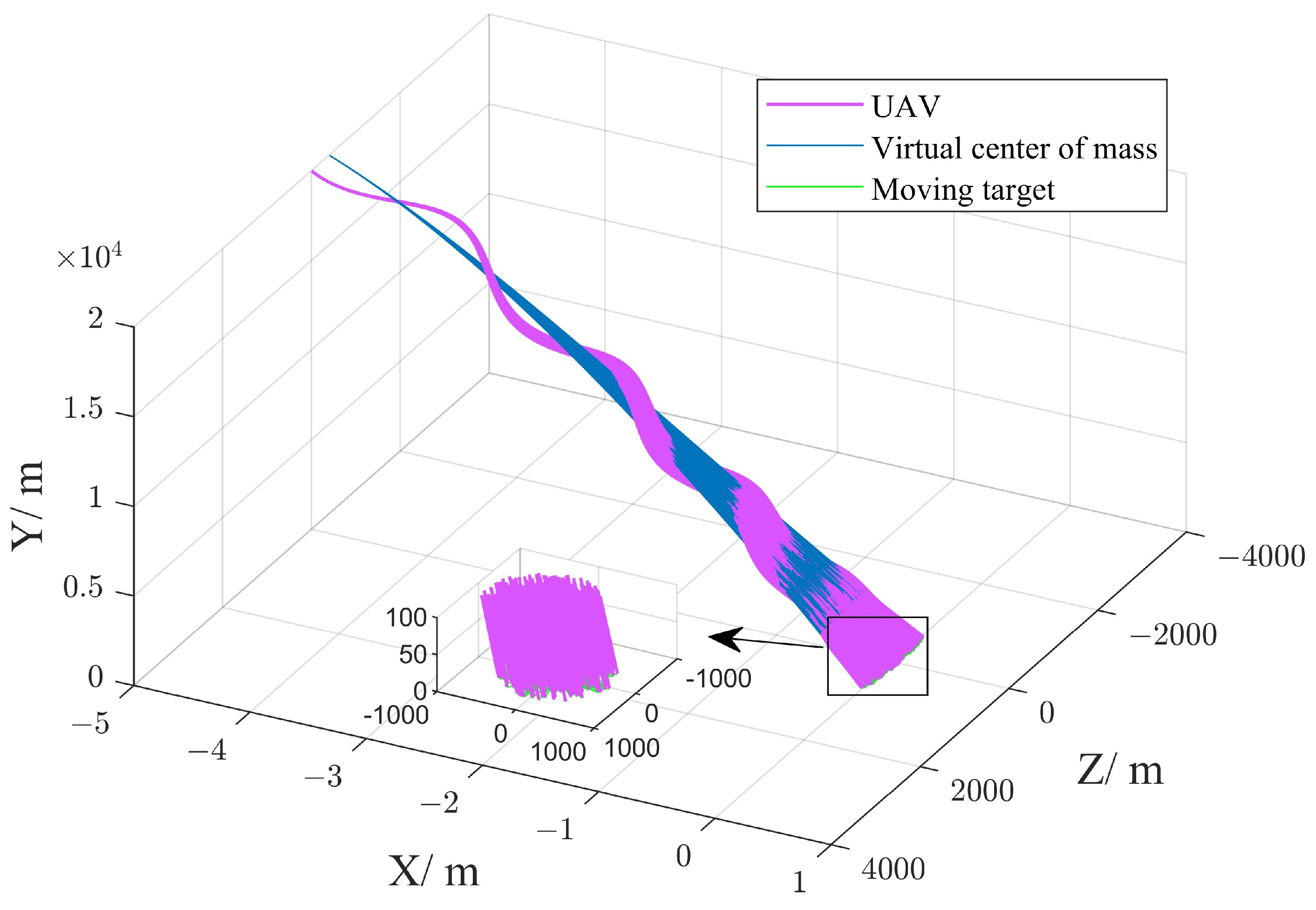
Figure 15 shows the 3D trajectory changes of 500 independent simulation experiments. As can be seen from Figure 15, although the target moves at different speeds and directions in each independent simulation experiment, the three-dimensional trajectory presents similar spiral characteristics due to the same set of spiral parameters.
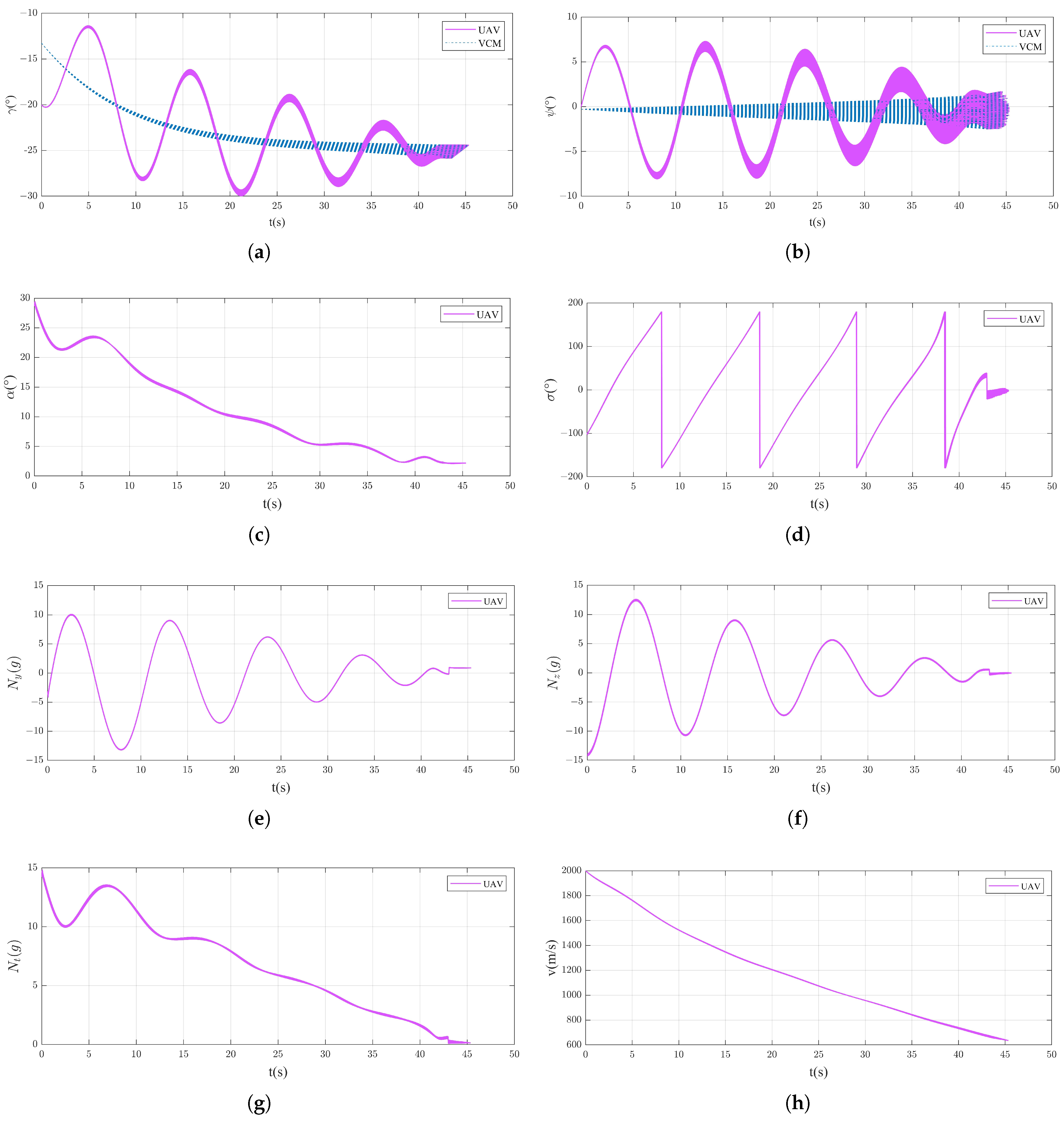
Figure 16 illustrates the variations in the UAV states observed across 500 Monte Carlo simulations. Given the low velocity of the target, minimal discernible variation is exhibited among trajectories in aerodynamic control parameters, including attack angle, bank angle and overload. However, as depicted in Figure 16c–g, the UAV achieves convergence in its spiral trajectory, thereby ensuring full positional and velocity synchronization between the UAV and the VCM. Following this alignment, the system proceeds to generate subsequent high-precision strike trajectories. The transition between these operational phases introduces minor discontinuities in control commands, attributable to the abrupt shift from maneuver trajectory to precision-guided execution.
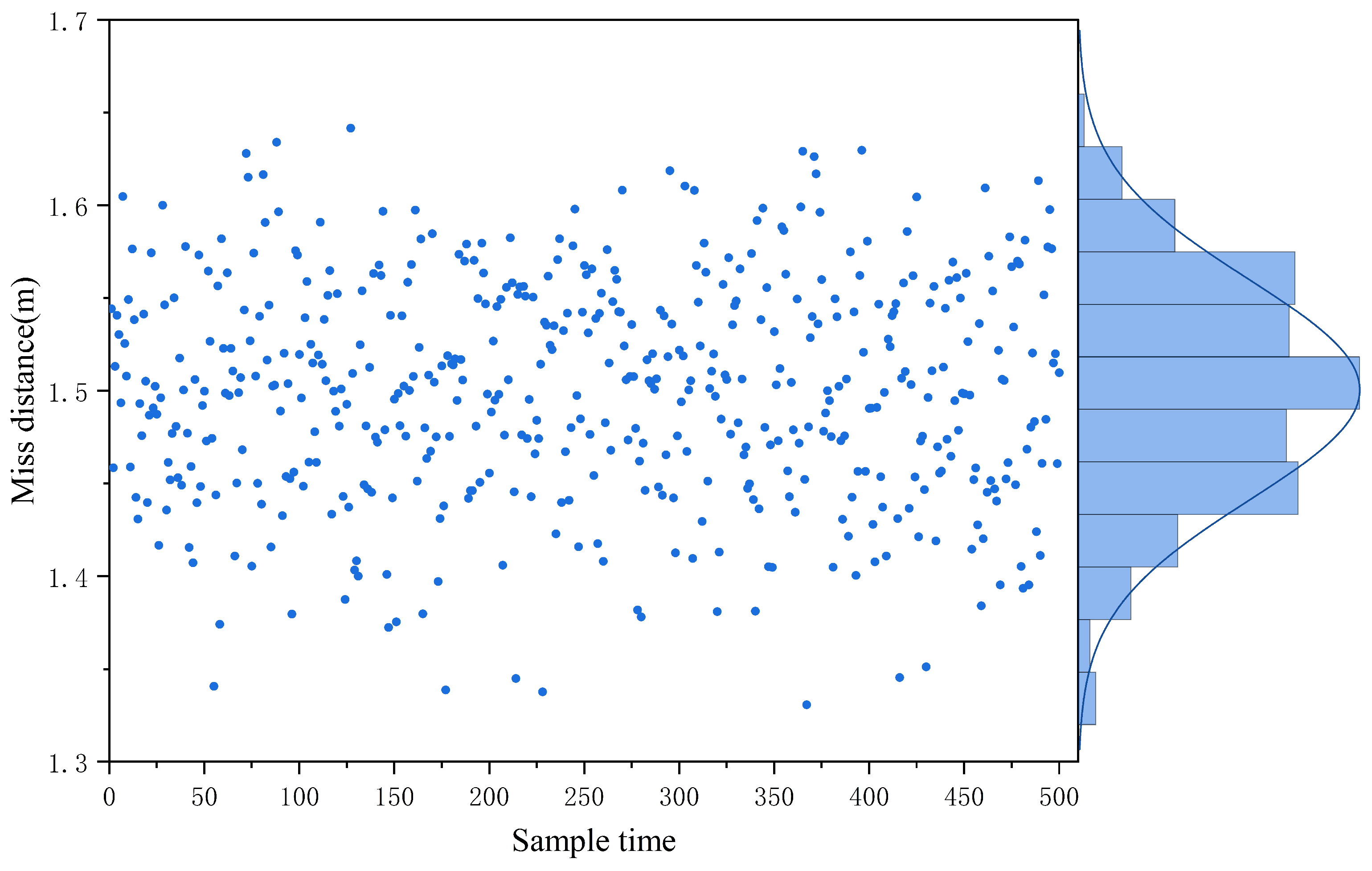
The distribution of terminal miss distances is delineated in Figure 17. Empirical analysis reveals a mean miss distance of μ = 1.50 m , a standard deviation of σ = 0.059 m and a maximum miss distance of max d m i s s = 1.64 m . These metrics demonstrate that the DRL-trained intelligent agent synthesizes spiral maneuver ballistic trajectories with sub-meter precision (mean error < 2 σ ), achieving high strike accuracy while compensating for dynamic target displacement scenarios. The results underscore the efficacy of the proposed framework in reconciling adversarial evasion with terminal precision.

4.3. Analysis of Computational Complexity

The strategy network for generating virtual trajectories online based on the PPO algorithm training is a four-layer fully connected neural network with R DM , R ˙ DM , q D M , q ˙ D M , λ D M , λ ˙ D M T as the input and n y , n z T as the output, containing 34,952 parameters. When applying this strategy network in practice, the computer only needs to perform four matrix multiplications to map R DM , R ˙ DM , q D M , q ˙ D M , λ D M , λ ˙ D M T to n y , n z T . Meanwhile, storing each parameter as a 32-bit floating-point number only occupies approximately 136.5 KB of storage space.
Using the STM32F407 single-chip microcontroller (STMicroelectronics, Geneva, Switzerland) as the experimental platform and adopting the double data type, an algorithm time consumption experiment was conducted. When applying the decision algorithm in this paper, only running the strategy network is required. The time consumption of the strategy network obtained from the timer function of the single-chip microcontroller is approximately 4.3 ms, indicating good real-time performance and the possibility of application on the on-board computer.

5. Conclusions

This study resolves the inherent dichotomy between evasion maneuverability and terminal strike precision in hypersonic UAV systems through a dual-layer trajectory architecture. The proposed framework integrates a nominal virtual trajectory, optimized for terminal guidance accuracy, with a superimposed relative spiral trajectory to induce evasion. In the design of the relative spiral, the innovative use of an Archimedean spiral is adopted, which enables the gradual convergence to the virtual trajectory while conducting maneuvering penetration, providing a foundation for a precise strike. Meanwhile, this method can precisely adjust the spiral radius and frequency. In the design of the virtual trajectory, a MDP is constructed, and the virtual trajectory generation strategy is obtained through training based on the PPO algorithm, effectively enhancing the target perception ability of the UAV and improving the adjustment ability for the maneuvering trajectory.
From the simulation results, the methodology yields an average miss distance of 1.5 m, with a maximum deviation of merely 1.64 m under parameters of a 400 m spiral radius and 4 spiral turns. It can be seen that the spiral maneuvering trajectory realized in this paper achieves large-scale spiral maneuvering and high-precision strike capabilities.

Author Contributions

Conceptualization, T.C. and S.L.; methodology, T.C.; software, T.C.; validation, T.C. and L.R.; formal analysis, T.C.; investigation, T.C.; resources, Y.X.; data curation, Z.L.; writing—original draft preparation, T.C.; writing—review and editing, S.L.; visualization, T.C.; supervision, Y.X. All authors have read and agreed to the published version of the manuscript.

Funding

This research received no external funding.

Data Availability Statement

The original contributions presented in the study are included in the article, further inquiries can be directed to the corresponding author.

DURC Statement

Current research is limited to the development of intelligent trajectory generation algorithms for UAV spiral maneuvering, which is beneficial to advancing UAV trajectory generation algorithm research and does not pose a threat to public health or national security. The authors acknowledge the dual-use potential of the research involving artificial intelligence methods and spiral maneuvering trajectory design methods and confirm that all necessary precautions have been taken to prevent potential misuse. As an ethical responsibility, the authors strictly adhere to relevant national and international laws about DURC. The authors advocate for responsible deployment, ethical considerations, regulatory compliance and transparent reporting to mitigate misuse risks and foster beneficial outcomes.

Conflicts of Interest

The authors declare no conflicts of interest.

Abbreviations

The following abbreviations are used in this manuscript:
UAVUnmanned aerial vehicle
DRLDeep reinforcement learning
MDPMarkov decision process
LOSLine of sight
VCMVirtual center of mass
RLReinforcement learning
GAEGeneralized advantage estimation
PPOProximal policy optimization

References

  1. Guo, D.; Dong, X.; Li, D.; Ren, Z. Feasibility Analysis for Cooperative Interception of Hypersonic Maneuvering Target. In Proceedings of the 2019 Chinese Control Conference (CCC), Guangzhou, China, 27–30 July 2019; pp. 4066–4071. [Google Scholar]
  2. Bużantowicz, W. Tuning of a Linear-Quadratic Stabilization System for an Anti-Aircraft Missile. Aerospace 2021, 8, 48. [Google Scholar] [CrossRef]
  3. Hu, Y.; Gao, C.; Li, J.; Jing, W. Maneuver mode analysis and parametric modeling for hypersonic glide vehicles. Aerosp. Sci. Technol. 2021, 119, 107166. [Google Scholar] [CrossRef]
  4. Zhao, S.; Zhu, J.; Bao, W.; Li, X.; Sun, H. A multi-constraint guidance and maneuvering penetration strategy via meta deep reinforcement learning. Drones 2023, 7, 626. [Google Scholar] [CrossRef]
  5. Luo, C.; Huang, C.; Ding, D.; Guo, H. Design of weaving penetration for hypersonic glide vehicle. Electron. Opt. Control 2013, 7, 67–72. [Google Scholar]
  6. Zhang, J.; Xiong, J.; Li, L.; Xi, Q.; Chen, X.; Li, F. Motion state recognition and trajectory prediction of hypersonic glide vehicle based on deep learning. IEEE Access 2022, 10, 21095–21108. [Google Scholar] [CrossRef]
  7. Zhu, J.; He, R.; Tang, G.; Bao, W. Pendulum maneuvering strategy for hypersonic glide vehicles. Aerosp. Sci. Technol. 2018, 78, 62–70. [Google Scholar] [CrossRef]
  8. Li, G.; Zhang, H.; Tang, G. Maneuver characteristics analysis for hypersonic glide vehicles. Aerosp. Sci. Technol. 2015, 43, 321–328. [Google Scholar] [CrossRef]
  9. Ohlmeyer, E.J. Root-mean-square miss distance of proportional navigation missile against sinusoidal target. J. Guid. Control. Dyn. 1996, 19, 563–568. [Google Scholar] [CrossRef]
  10. Kim, J.; Vaddi, S.; Menon, P.; Ohlmeyer, E. Comparison between three spiraling ballistic missile state estimators. In Proceedings of the AIAA Guidance, Navigation and Control Conference and Exhibit, Honolulu, HI, USA, 18–21 August 2008; p. 7459. [Google Scholar]
  11. Yanushevsky, R. Analysis of optimal weaving frequency of maneuvering targets. J. Spacecr. Rocket. 2004, 41, 477–479. [Google Scholar] [CrossRef]
  12. Zhao, K.; Cao, D.; Huang, W. Maneuver control of the hypersonic gliding vehicle with a scissored pair of control moment gyros. Sci. China Technol. Sci. 2018, 61, 1150–1160. [Google Scholar] [CrossRef]
  13. Liang, Z.; Xiong, F. A Maneuvering Penetration Guidance Law Based on Variable Structure Control. In Proceedings of the 2020 39th Chinese Control Conference (CCC), Shenyang, China, 27–30 July 2020; pp. 2067–2071. [Google Scholar]
  14. Bin, Z.; Tianze, L.; Tianyang, X.; Changshu, W. Cooperative guidance for maneuvering penetration with attack time consensus and bounded input. Int. J. Aeronaut. Space Sci. 2024, 25, 1395–1411. [Google Scholar] [CrossRef]
  15. Kim, Y.H.; Ryoo, C.K.; Tahk, M.J. Guidance synthesis for evasive maneuver of anti-ship missiles against close-in weapon systems. IEEE Trans. Aerosp. Electron. Syst. 2010, 46, 1376–1388. [Google Scholar] [CrossRef]
  16. Yu, X.; Luo, S.; Liu, H. Integrated design of multi-constrained snake maneuver surge guidance control for hypersonic vehicles in the dive segment. Aerospace 2023, 10, 765. [Google Scholar] [CrossRef]
  17. He, L.; Yan, X. Adaptive terminal guidance law for spiral-diving maneuver based on virtual sliding targets. J. Guid. Control. Dyn. 2018, 41, 1591–1601. [Google Scholar] [CrossRef]
  18. Jiang, Q.; Wang, X.; Bai, Y.; Li, Y. Intelligent Online Multiconstrained Reentry Guidance Based on Hindsight Experience Replay. Int. J. Aerosp. Eng. 2023, 2023, 5883080. [Google Scholar] [CrossRef]
  19. Li, G.; Li, S.; Li, B.; Wu, Y. Deep Reinforcement Learning Guidance with Impact Time Control. J. Syst. Eng. Electron. 2024, 35, 1594–1603. [Google Scholar] [CrossRef]
  20. Wang, N.; Wang, X.; Cui, N.; Li, Y.; Liu, B. Deep reinforcement learning-based impact time control guidance law with constraints on the field-of-view. Aerosp. Sci. Technol. 2022, 128, 107765. [Google Scholar] [CrossRef]
  21. Fan, J.; Dou, D.; Ji, Y. Impact-angle constraint guidance and control strategies based on deep reinforcement learning. Aerospace 2023, 10, 954. [Google Scholar] [CrossRef]
  22. Lee, S.; Lee, Y.; Kim, Y.; Han, Y.; Kwon, H.; Hong, D. Impact angle control guidance considering seeker’s field-of-view limit based on reinforcement learning. J. Guid. Control. Dyn. 2023, 46, 2168–2182. [Google Scholar] [CrossRef]
  23. Jiang, L.; Nan, Y.; Zhang, Y.; Li, Z. Anti-interception guidance for hypersonic glide vehicle: A deep reinforcement learning approach. Aerospace 2022, 9, 424. [Google Scholar] [CrossRef]
  24. Yan, T.; Liu, C.; Gao, M.; Jiang, Z.; Li, T. A Deep Reinforcement Learning-Based Intelligent Maneuvering Strategy for the High-Speed UAV Pursuit-Evasion Game. Drones 2024, 8, 309. [Google Scholar] [CrossRef]
  25. Tripathy, T.; Shima, T. Archimedean spiral-based intercept angle guidance. J. Guid. Control. Dyn. 2019, 42, 1105–1115. [Google Scholar] [CrossRef]
  26. Schulman, J.; Moritz, P.; Levine, S.; Jordan, M.; Abbeel, P. High-dimensional continuous control using generalized advantage estimation. arXiv 2015, arXiv:1506.02438. [Google Scholar]
  27. Schulman, J.; Wolski, F.; Dhariwal, P.; Radford, A.; Klimov, O. Proximal policy optimization algorithms. arXiv 2017, arXiv:1707.06347. [Google Scholar]
  28. Engstrom, L.; Ilyas, A.; Santurkar, S.; Tsipras, D.; Janoos, F.; Rudolph, L.; Madry, A. Implementation matters in deep policy gradients: A case study on ppo and trpo. arXiv 2020, arXiv:2005.12729. [Google Scholar]
  29. Phillips, T.H. A Common Aero Vehicle (CAV) Model, Description, and Employment Guide; Schafer Corporation: Arlington, VA, USA, 2003. [Google Scholar]
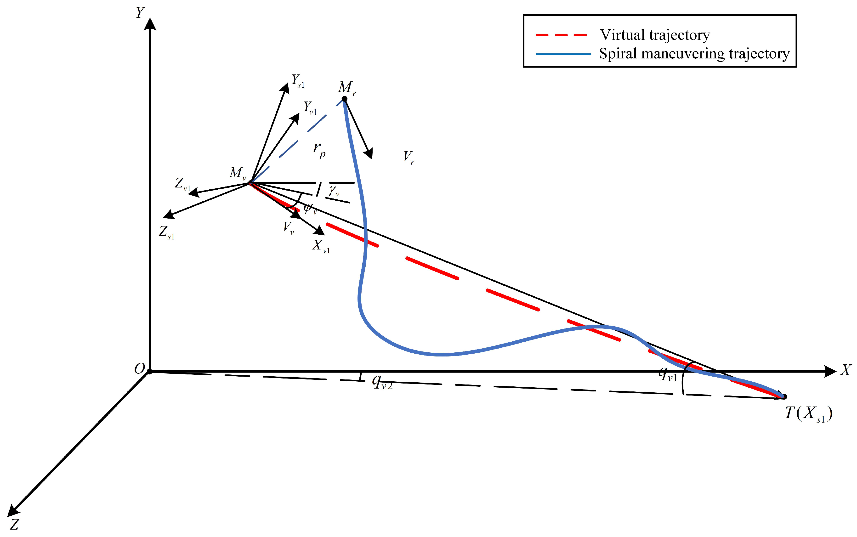
Figure 1. Spiral maneuvering trajectory diagram.
Drones 09 00446 g001
Figure 2. Relative motion relation.
Drones 09 00446 g002
Figure 3. Archimedean spiral diagram.
Drones 09 00446 g003
Figure 4. Schematic diagram of interaction between RL agent and environment.
Drones 09 00446 g004
Figure 5. Reward function diagram.
Drones 09 00446 g005
Figure 6. Policy network.
Drones 09 00446 g006
Figure 7. Spiral maneuver trajectory generation flow chart.
Drones 09 00446 g007
Figure 8. Training process.
Drones 09 00446 g008
Figure 9. Spiral maneuvering 3D trajectory with different parameters.
Drones 09 00446 g009
Figure 10. (a) Velocity slope angle vs. time graph with different parameters. (b) Velocity azimuth vs. time graph with different parameters.
Drones 09 00446 g010
Figure 11. Attack angle vs. time graph with different parameters.
Drones 09 00446 g011
Figure 12. Attack angle vs. time graph with different parameters.
Drones 09 00446 g012
Figure 13. (a) Lateral overload vs. time graph with different parameters. (b) Normal overload vs. time graph with different parameters.
Drones 09 00446 g013
Figure 14. Velocity vs. time graph with different parameters.
Drones 09 00446 g014
Figure 15. Three-dimensional trajectory of Monte Carlo simulations.
Drones 09 00446 g015
Figure 16. (a) Velocity slope angle vs. time graph of Monte Carlo simulations. (b) Velocity azimuth vs. time graph of Monte Carlo simulations. (c) Attack angle vs. time graph of Monte Carlo simulations. (d) Bank angle vs. time graph of Monte Carlo simulations. (e) Lateral overload vs. time graph of Monte Carlo simulations. (f) Normal overload vs. time graph of Monte Carlo simulations. (g) Total overload vs. time graph of Monte Carlo simulations. (h) Velocity vs. time graph of Monte Carlo simulations.
Drones 09 00446 g016
Figure 17. Miss-distance distribution.
Drones 09 00446 g017
Table 1. Coordinate system transformation angles.
Serial NumberEuler AngleDefinition Description
1 γ r , ψ r The angular relationship between the M r X r 1 Y r 1 Z r 1 and O X Y Z coordinate systems is defined by the velocity slope angle and velocity azimuth of the UAV.
2 γ v , ψ v The angular relationship between the M v X v 1 Y v 1 Z v 1 and O X Y Z coordinate systems is defined by the virtual velocity slope angle and virtual velocity azimuth of the VCM.
3 q r 1 , q r 2 The angular relationship between the M r X s 2 Y s 2 Z s 2 and O X Y Z coordinate systems is defined by the LOS altitude angle and azimuth angle of the UAV.
4 q v 1 , q v 2 The angular relationship between the M v X s 1 Y s 1 Z s 1 and O X Y Z coordinate systems is defined by the LOS altitude angle and azimuth angle of the VCM.
Table 2. Network structure and parameters.
Network LevelActor NetworkCritic Network
UnitsActivation FunctionUnitsActivation Function
Input layer6None6None
Hidden layer 1128Tanh128Tanh
Hidden layer 2128Tanh128Tanh
Hidden layer 3128Tanh128Tanh
Output layer4Tanh/Linear1Linear
Table 3. Simulation correlation parameter.
ObjectPhysical QuantityValue
UAV x r ( 0 ) , y r ( 0 ) , z r ( 0 ) −50 km, 20 km, 0 km
V ( 0 ) , γ ( 0 ) , ψ ( 0 ) 2000 m/s, −20°, 0°
Target x t ( 0 ) , y t ( 0 ) , z t ( 0 ) 0 m, 0 m, 0 m
Table 4. Hyperparameter values.
HyperparameterValueHyperparameterValue
k s 0.01 c VF 0.25
r e th , 1 10.0 c s 0.01
r e th , 2 50.0 g max 0.5
r e th , 3 51.0 ε 0.2
R miss th , 1 2.0 α lr , 0 0.0001
R miss th , 2 100.0 β lr , 0 0.0001
D 20,000 N epoch 400
B 128 N update 200
γ 0.995 N rollout 20
λ 0.95 n max ( g ) 5.0
Disclaimer/Publisher’s Note: The statements, opinions and data contained in all publications are solely those of the individual author(s) and contributor(s) and not of MDPI and/or the editor(s). MDPI and/or the editor(s) disclaim responsibility for any injury to people or property resulting from any ideas, methods, instructions or products referred to in the content.