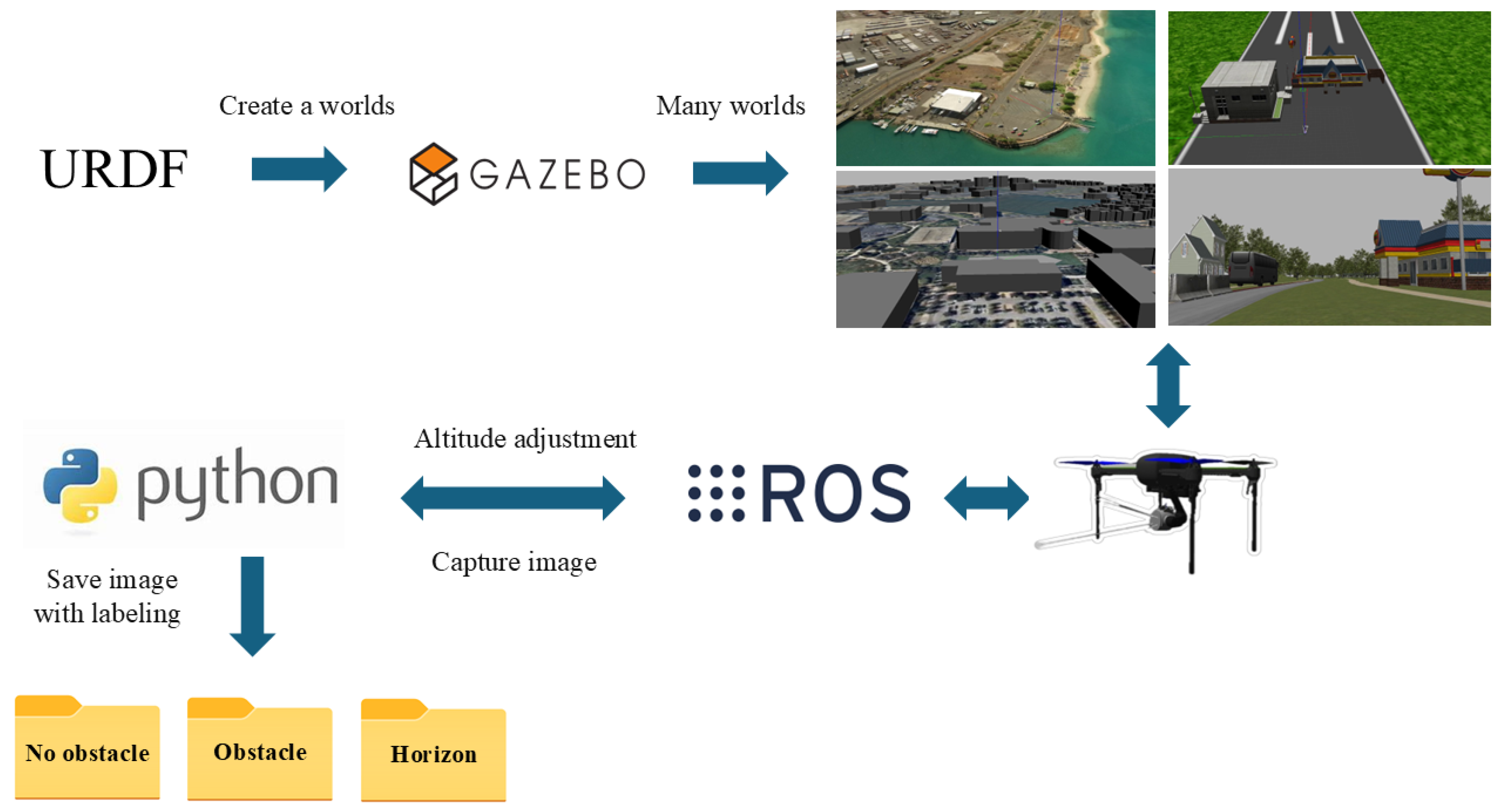
Figure 1.
Dataset creation framework.
Figure 1.
Dataset creation framework.
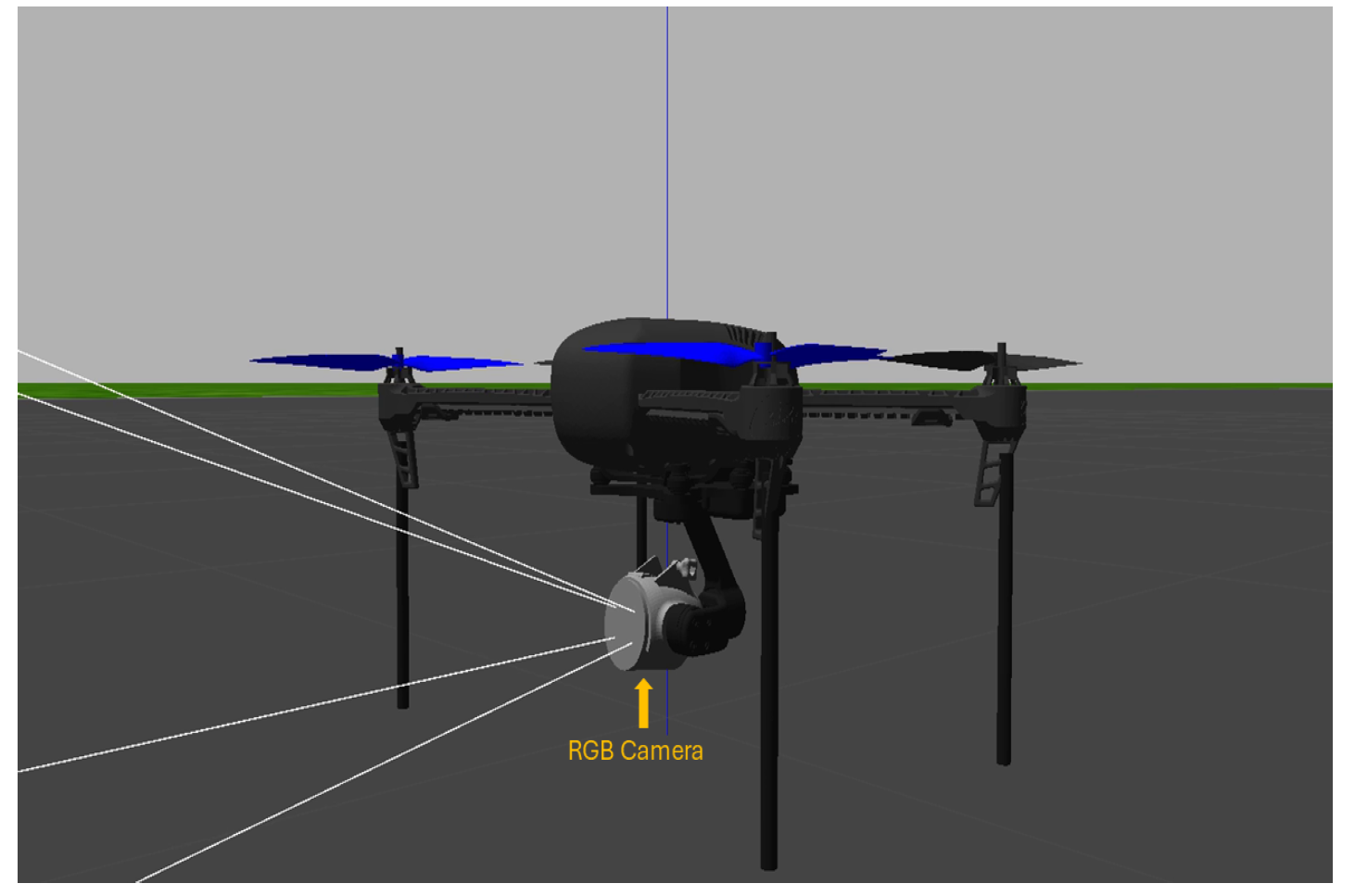
Figure 2.
The images are collected from the Gazebo simulator using a quadcopter equipped with an RGB camera.
Figure 2.
The images are collected from the Gazebo simulator using a quadcopter equipped with an RGB camera.
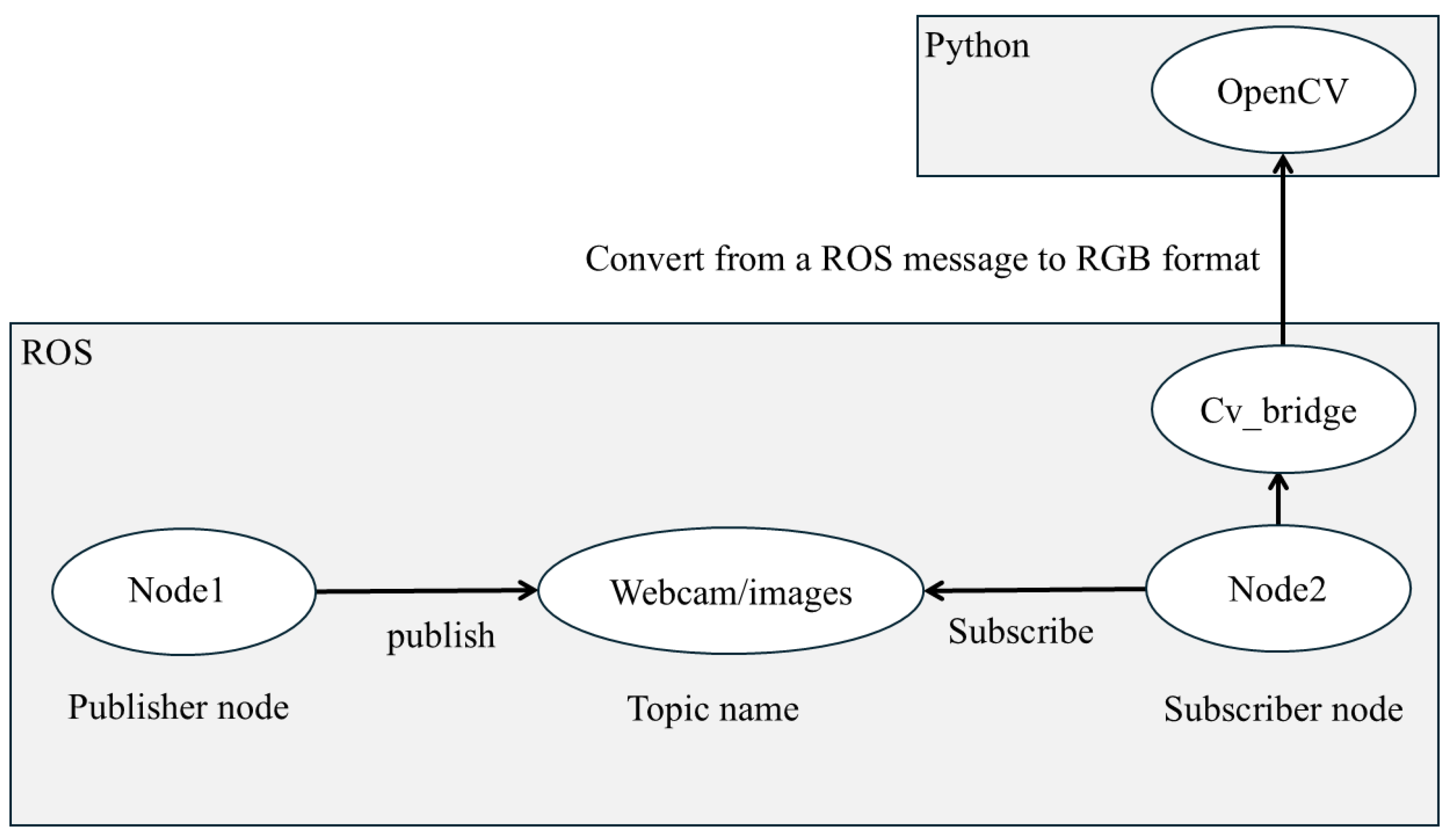
Figure 3.
The image processing path obtained with the ROS and Python. Publisher node 1 captures data from a camera sensor and publishes it to the “webcam/images” topic. Subscriber node 2 subscribes to this topic to process the images. CvBridge is an ROS library that serves as an interface between the ROS and OpenCV, enabling image conversion from ROS to RGB.
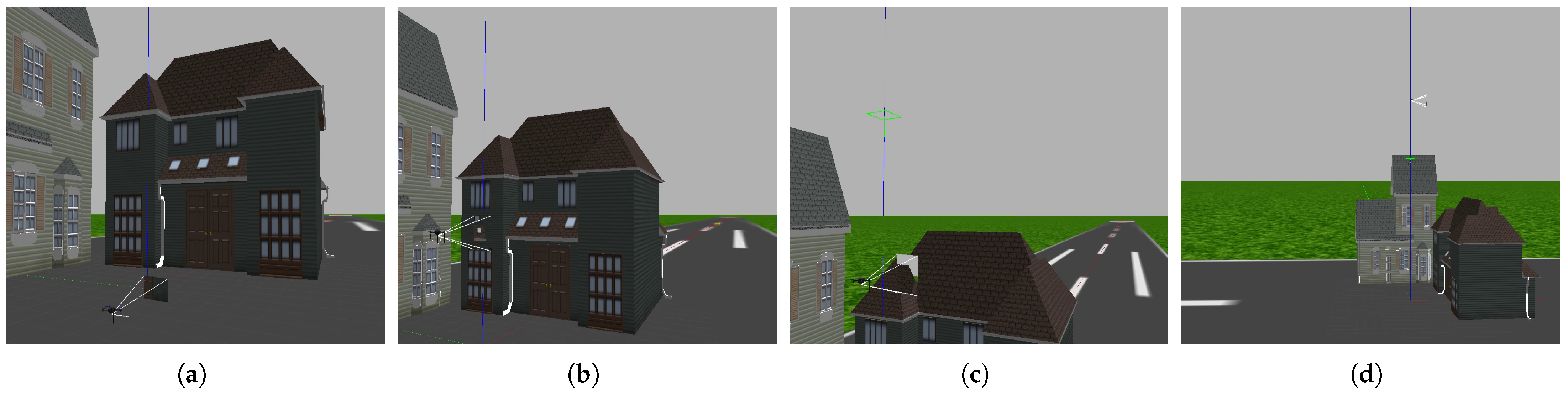
Figure 4.
Images (a–d) show the drone hovering at different altitudes to capture images from the runway.
Figure 4.
Images (a–d) show the drone hovering at different altitudes to capture images from the runway.
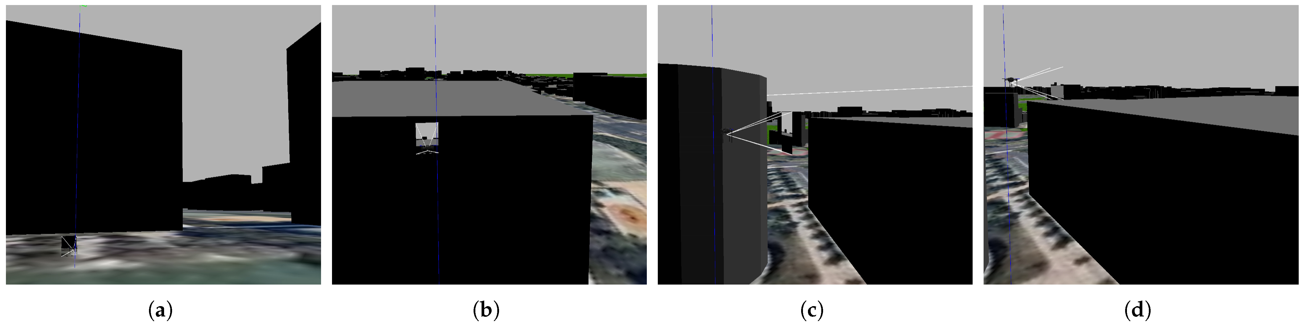
Figure 5.
Images (a–d) show the drone hovering at different altitudes to capture images from KSQL airport.
Figure 5.
Images (a–d) show the drone hovering at different altitudes to capture images from KSQL airport.
Figure 6.
Images were captured by a drone hovering close to the ground. In the dataset, images (a,b) showing trees and walls are labeled with the number 1 to indicate obstacles for the drone, while images (c,d) of the building are labeled with 0 to signify no obstacles.
Figure 6.
Images were captured by a drone hovering close to the ground. In the dataset, images (a,b) showing trees and walls are labeled with the number 1 to indicate obstacles for the drone, while images (c,d) of the building are labeled with 0 to signify no obstacles.
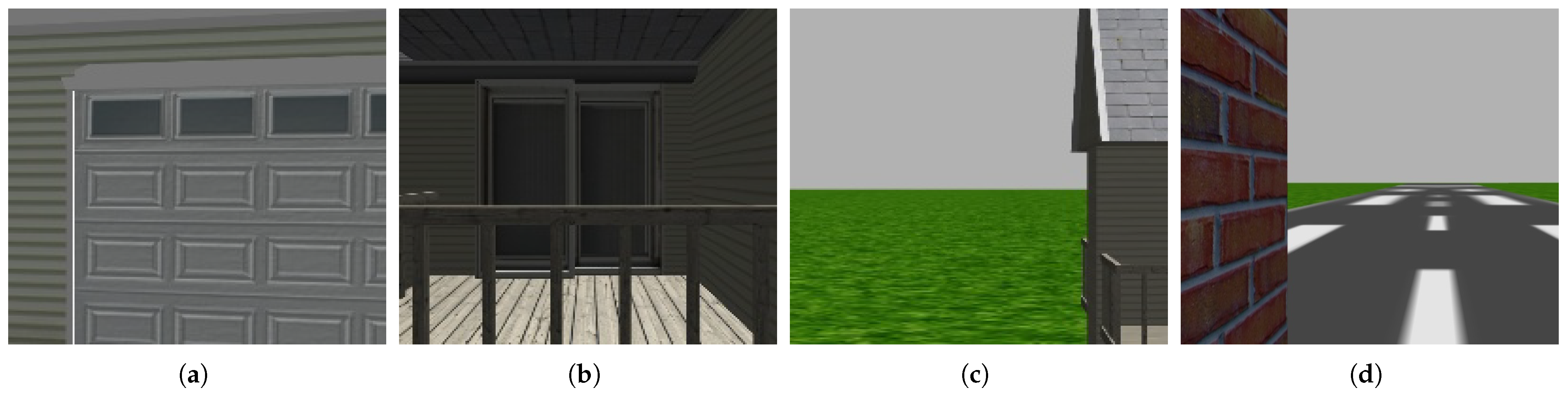
Figure 7.
Images of the middle of a building are captured as a drone ascends slightly above the ground. Images (a,b) are labeled with the number 1 to signify obstacles for the drone in our dataset. Images (c,d) are labeled with 0 to signify no obstacles.
Figure 7.
Images of the middle of a building are captured as a drone ascends slightly above the ground. Images (a,b) are labeled with the number 1 to signify obstacles for the drone in our dataset. Images (c,d) are labeled with 0 to signify no obstacles.
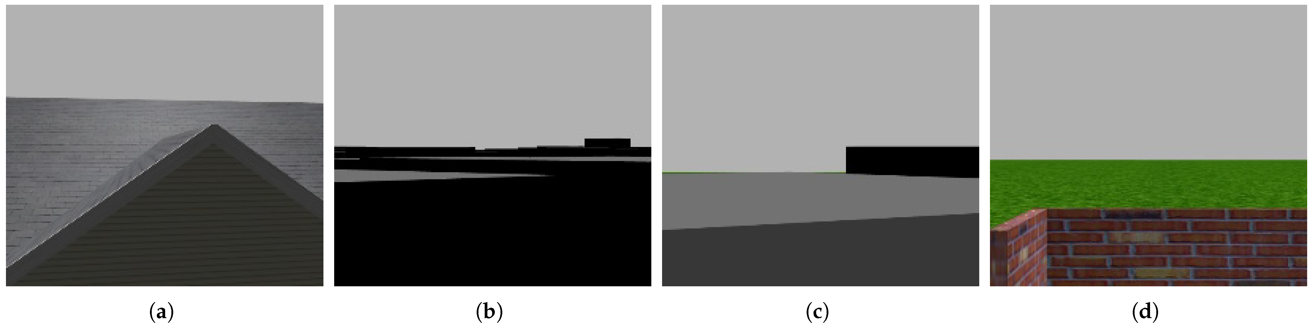
Figure 8.
The images were captured by a drone hovering close to the top of the obstacles. In the dataset, images (a,b) are labeled with the number 1 to indicate obstacles for the drone, while images (c,d) are labeled with 0 to signify no obstacles.
Figure 8.
The images were captured by a drone hovering close to the top of the obstacles. In the dataset, images (a,b) are labeled with the number 1 to indicate obstacles for the drone, while images (c,d) are labeled with 0 to signify no obstacles.
Figure 9.
A quadcopter capturing a horizon scene.
Figure 9.
A quadcopter capturing a horizon scene.
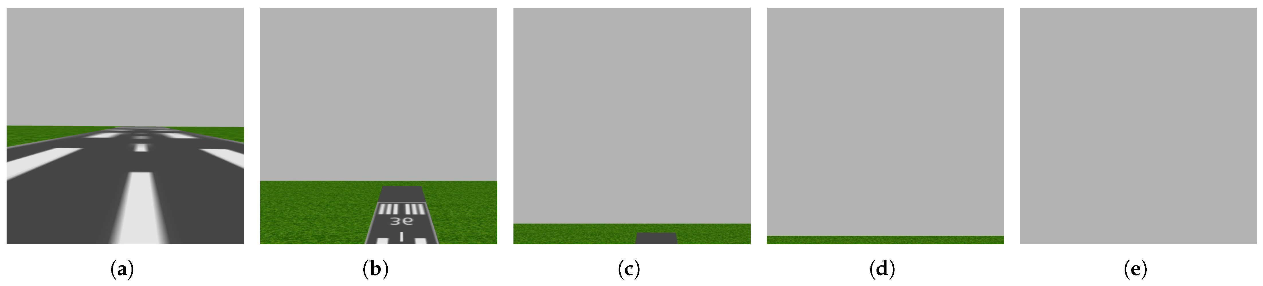
Figure 10.
The horizon is half of the scene in image (a), and it expands in the following images until the horizon is the entire scene in image (e). Images (a,b) are labeled with the number 0 to indicate no obstacles for the drone, while images (c–e) are labeled with 2 to signify the horizon.
Figure 10.
The horizon is half of the scene in image (a), and it expands in the following images until the horizon is the entire scene in image (e). Images (a,b) are labeled with the number 0 to indicate no obstacles for the drone, while images (c–e) are labeled with 2 to signify the horizon.
Figure 11.
The horizon is half of the scene in image (a), and it expands in the following images until the horizon is the entire scene in image (e). Images (a,b) are labeled with the number 0 to indicate no obstacles for the drone, while images (c–e) are labeled with 2 to signify the horizon.
Figure 11.
The horizon is half of the scene in image (a), and it expands in the following images until the horizon is the entire scene in image (e). Images (a,b) are labeled with the number 0 to indicate no obstacles for the drone, while images (c–e) are labeled with 2 to signify the horizon.
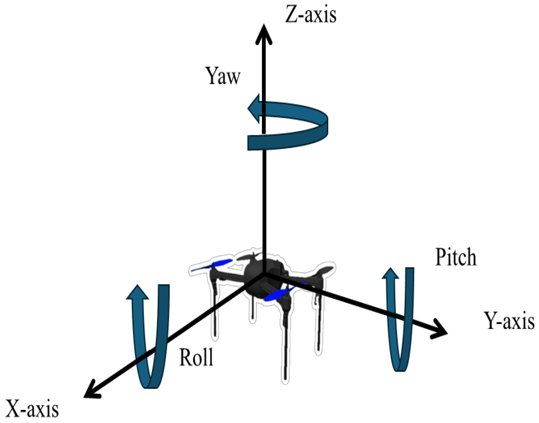
Figure 12.
Drone rotation during flight. The yaw angle is the rotation around the Z-axis. The roll angle is the rotation around the X-axis. The pitch angle is the rotation around the Y-axis.
Figure 12.
Drone rotation during flight. The yaw angle is the rotation around the Z-axis. The roll angle is the rotation around the X-axis. The pitch angle is the rotation around the Y-axis.
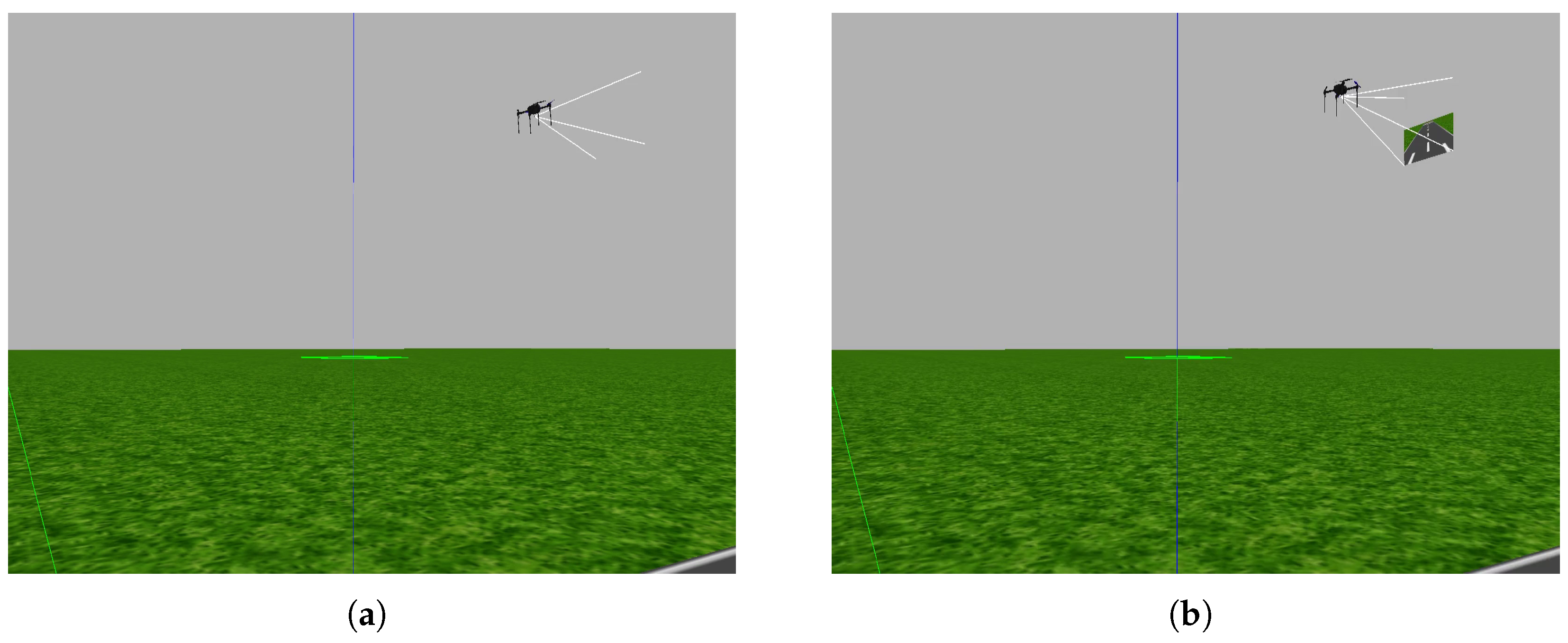
Figure 13.
In image (a), the horizon represents the entire scene captured by the camera due to the rotation of the drone around the Y-axis. In image (b), the view captured by the camera includes the ground as well as the horizon because the drone is not rotating around the Y-axis.
Figure 13.
In image (a), the horizon represents the entire scene captured by the camera due to the rotation of the drone around the Y-axis. In image (b), the view captured by the camera includes the ground as well as the horizon because the drone is not rotating around the Y-axis.
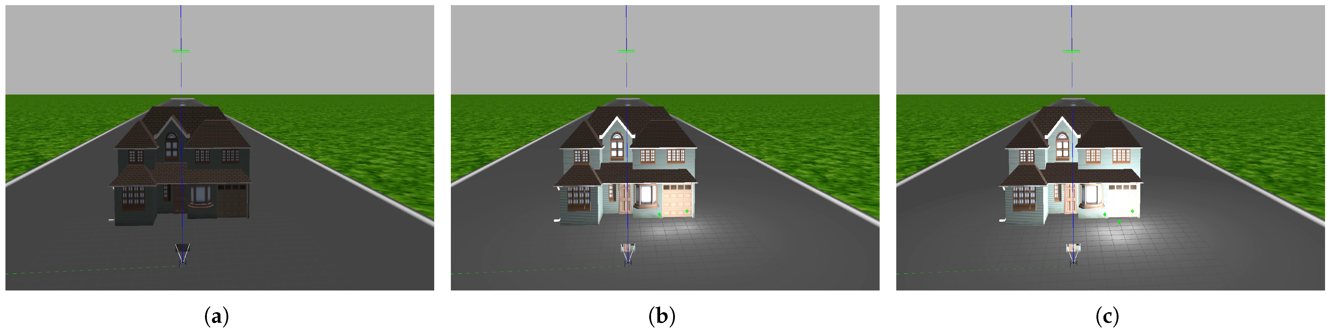
Figure 14.
The database includes images captured during the day and the night. Image (a): a night scene; image (b): a scene with sunlight; image (c): a high-brightness scene.
Figure 14.
The database includes images captured during the day and the night. Image (a): a night scene; image (b): a scene with sunlight; image (c): a high-brightness scene.
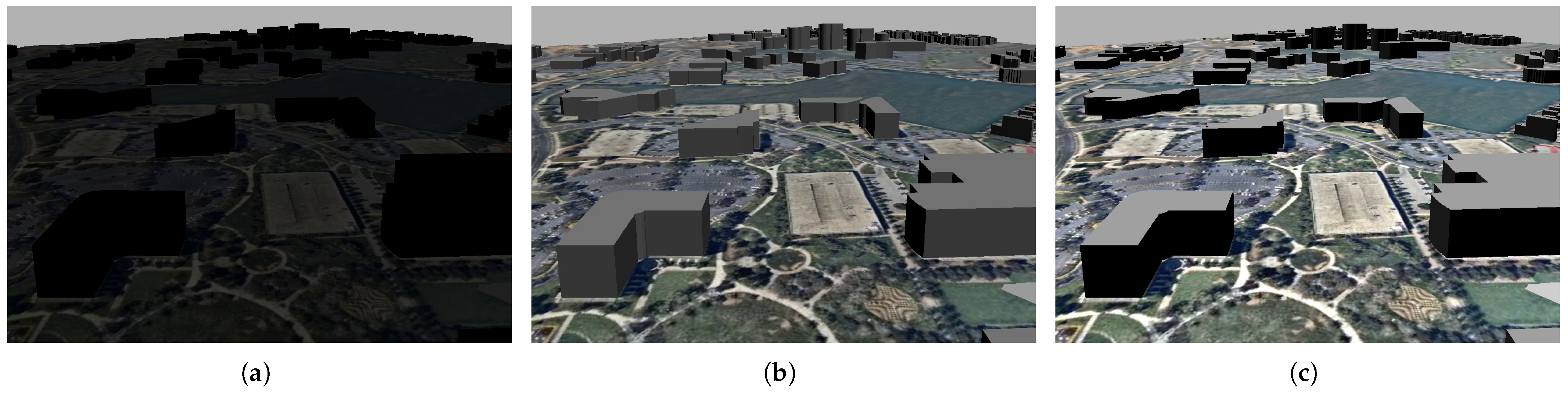
Figure 15.
The database includes an image with high brightness. In image (a), the scene is not bright. In image (b), the right side of the building is bright. In image (c), the brightness on the right side of the building hides its details.
Figure 15.
The database includes an image with high brightness. In image (a), the scene is not bright. In image (b), the right side of the building is bright. In image (c), the brightness on the right side of the building hides its details.
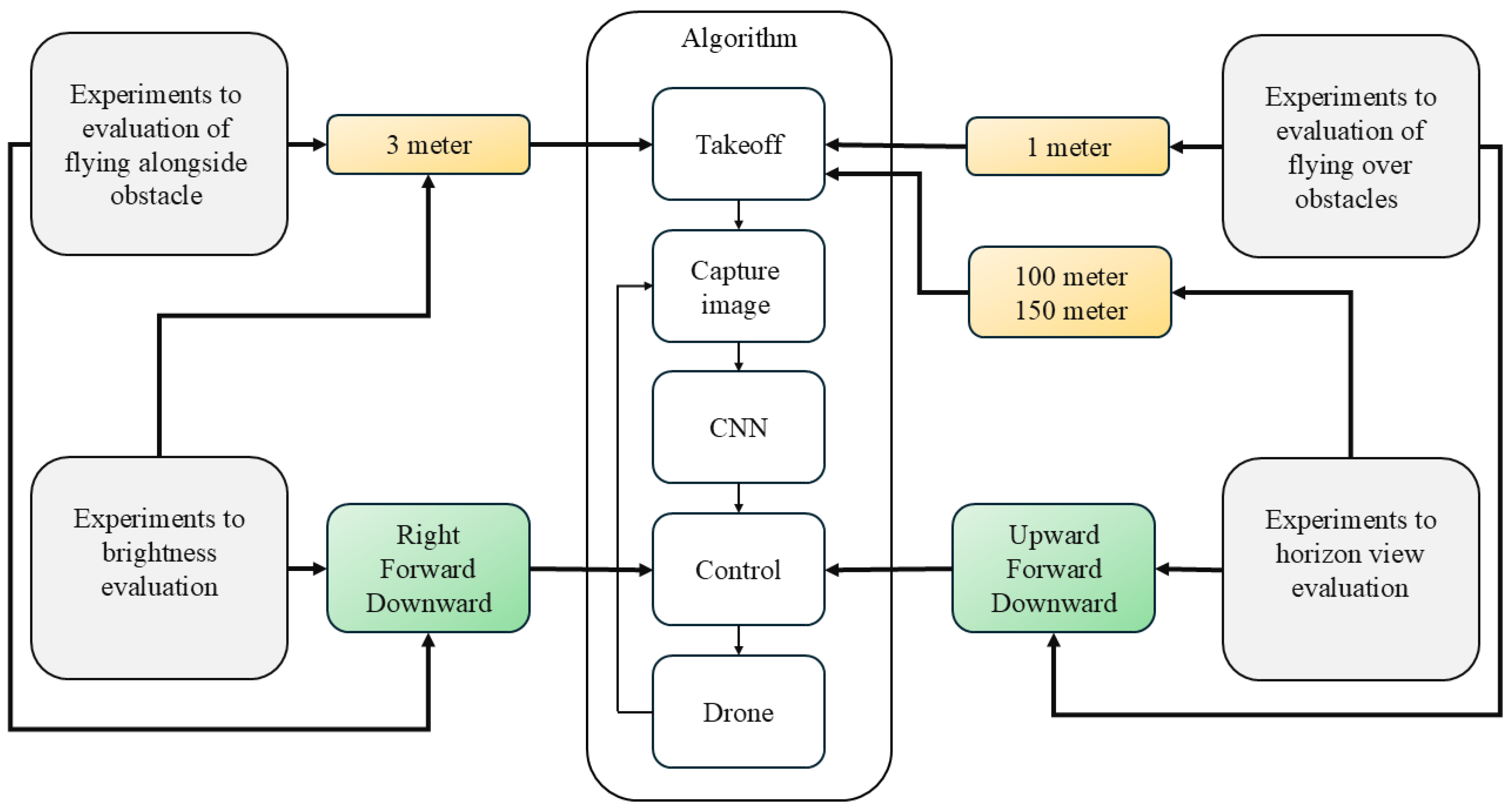
Figure 16.
Four types of experiments were conducted to evaluate flying over obstacles, the horizon view, flying alongside an obstacle, and brightness.
Figure 16.
Four types of experiments were conducted to evaluate flying over obstacles, the horizon view, flying alongside an obstacle, and brightness.
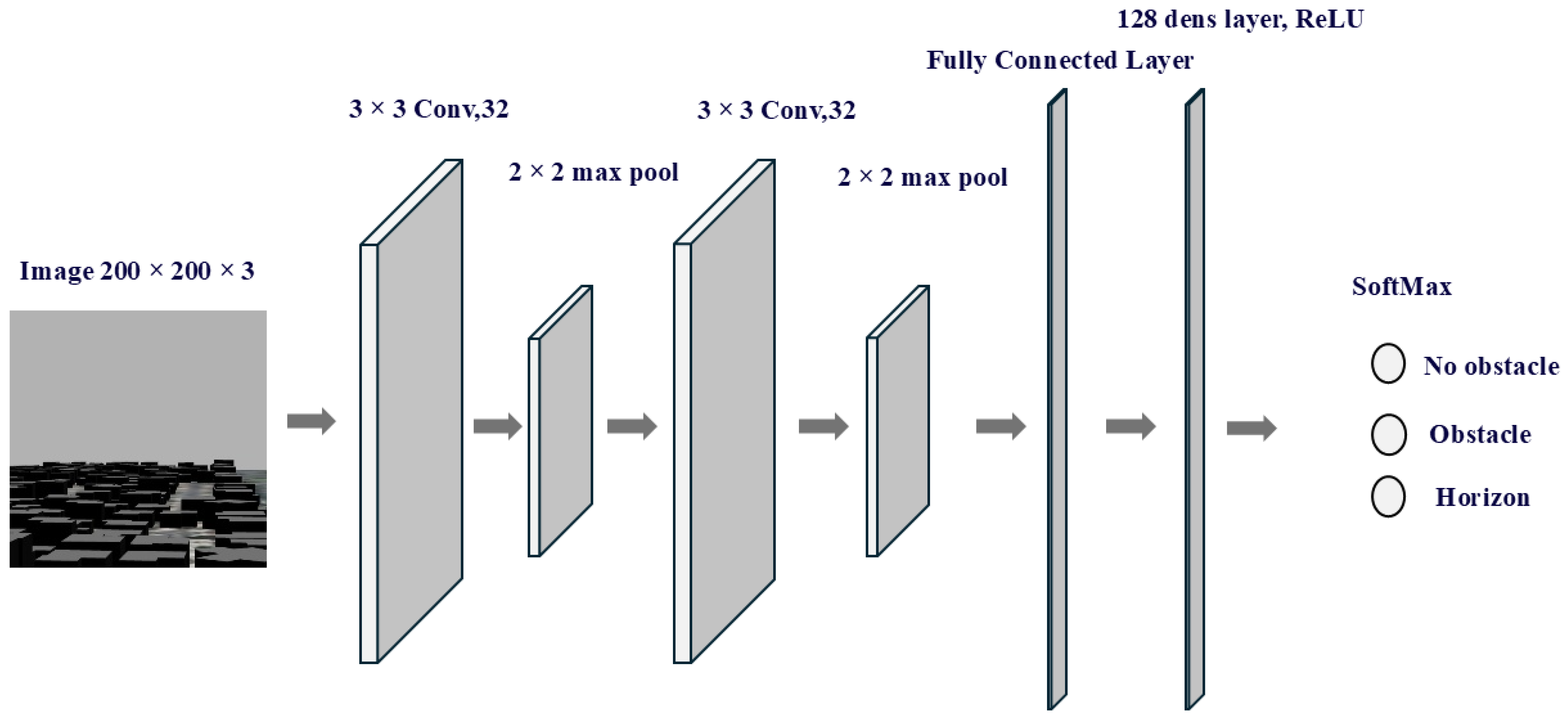
Figure 17.
The architecture of the CNN used to classify images into three categories: no-obstacle, obstacle, and horizon.
Figure 17.
The architecture of the CNN used to classify images into three categories: no-obstacle, obstacle, and horizon.
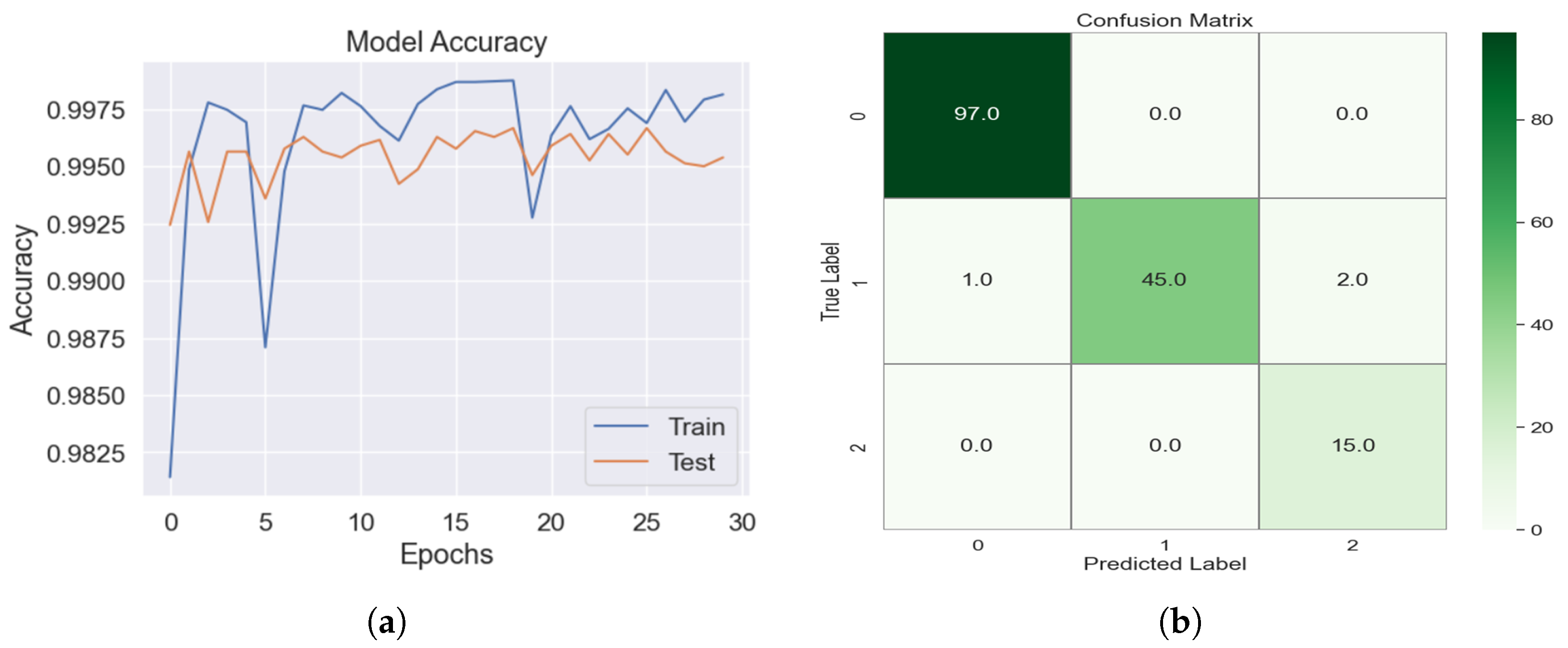
Figure 18.
(a) The accuracy of ANNs. (b) The confusion matrix for image classification using the validation dataset, where 0 indicates no obstacles, 1 indicates obstacles, and 2 indicates the horizon.
Figure 18.
(a) The accuracy of ANNs. (b) The confusion matrix for image classification using the validation dataset, where 0 indicates no obstacles, 1 indicates obstacles, and 2 indicates the horizon.
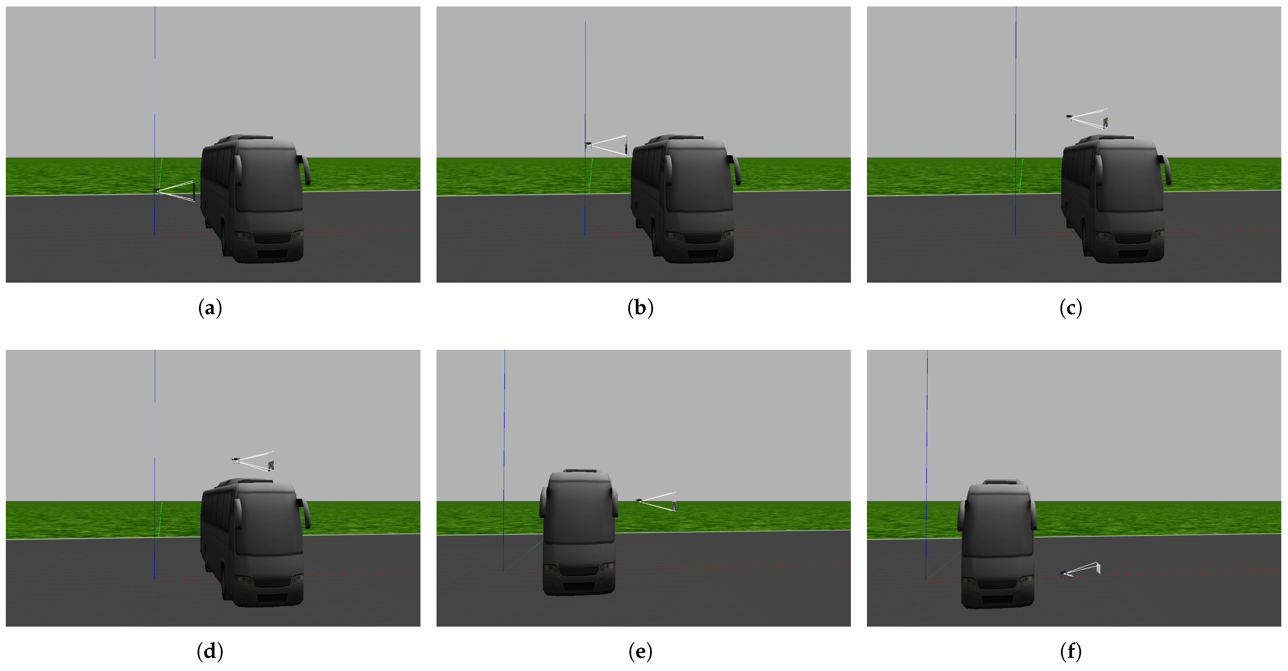
Figure 19.
The first experiment: The drone successfully flies over a bus and arrives at its target. In image (a), the drone detects the bus is in its path, so it moves upward. In image (b), the drone detects that the top of the bus is still an obstacle, so it moves upward. In images (c,d), the drone passes over the obstacle. In images (e,f), the drone reaches the target and lands on the ground.
Figure 20.
The second experiment: The drone successfully flies over the trees and arrives at its target roof. In image (a), the drone detects that trees are in its path, so it moves upward. In images (b,c), the drone detects that tree branches and leaves are still obstacles, so it moves upward In images (d,e), the drone passes over the trees. In image (f), the drone reaches the target and lands on the ground.
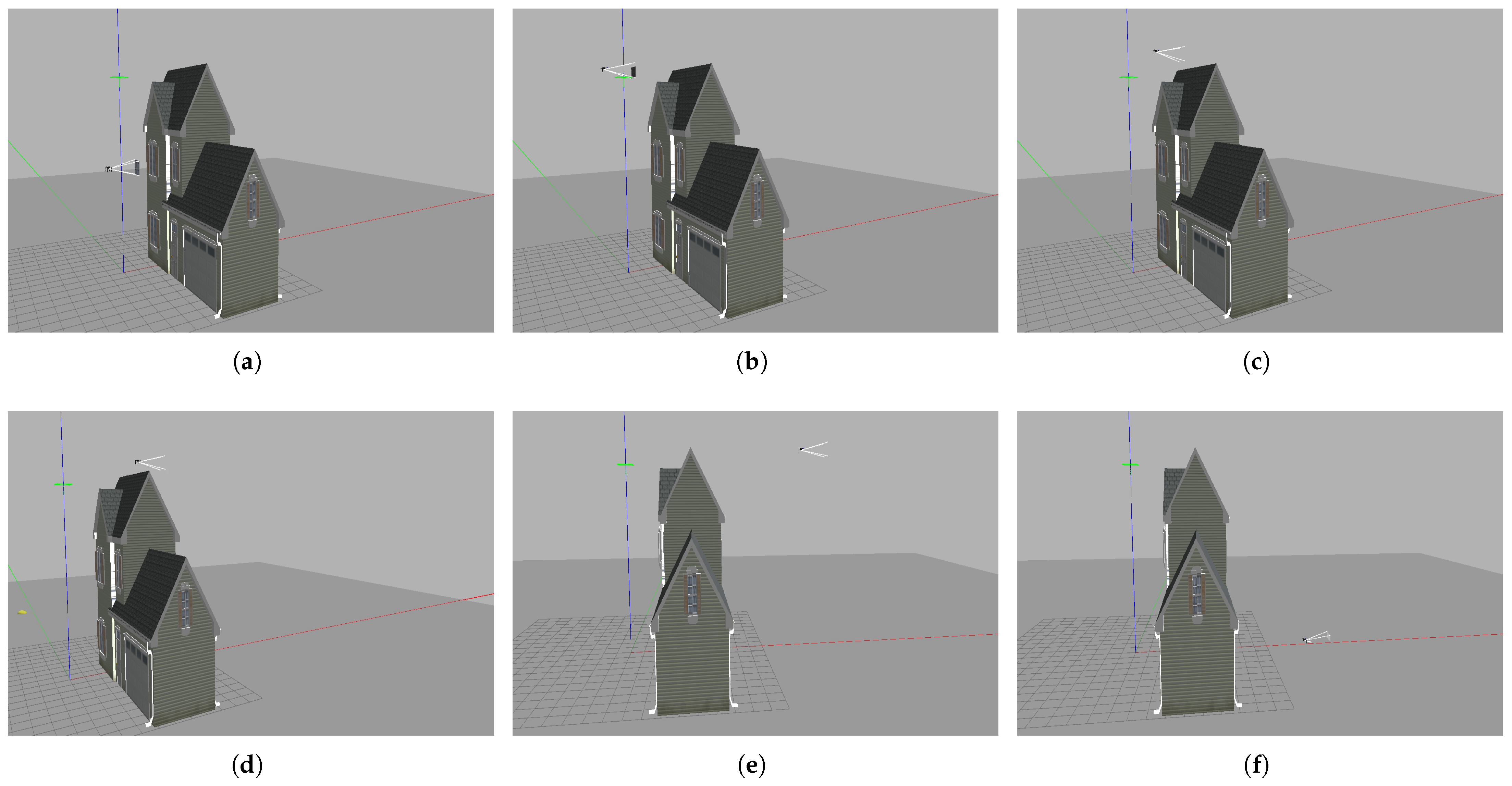
Figure 21.
The third experiment: The drone successfully flies over the building and arrives at its target. In image (a), the drone detects that the middle of the building is in its path, so it moves upward. In image (b), the drone detects that the top of the building is an obstacle, so it moves upward. In images (c,d), the drone passes over the building. In images (e,f), the drone reaches the target and lands on the ground.
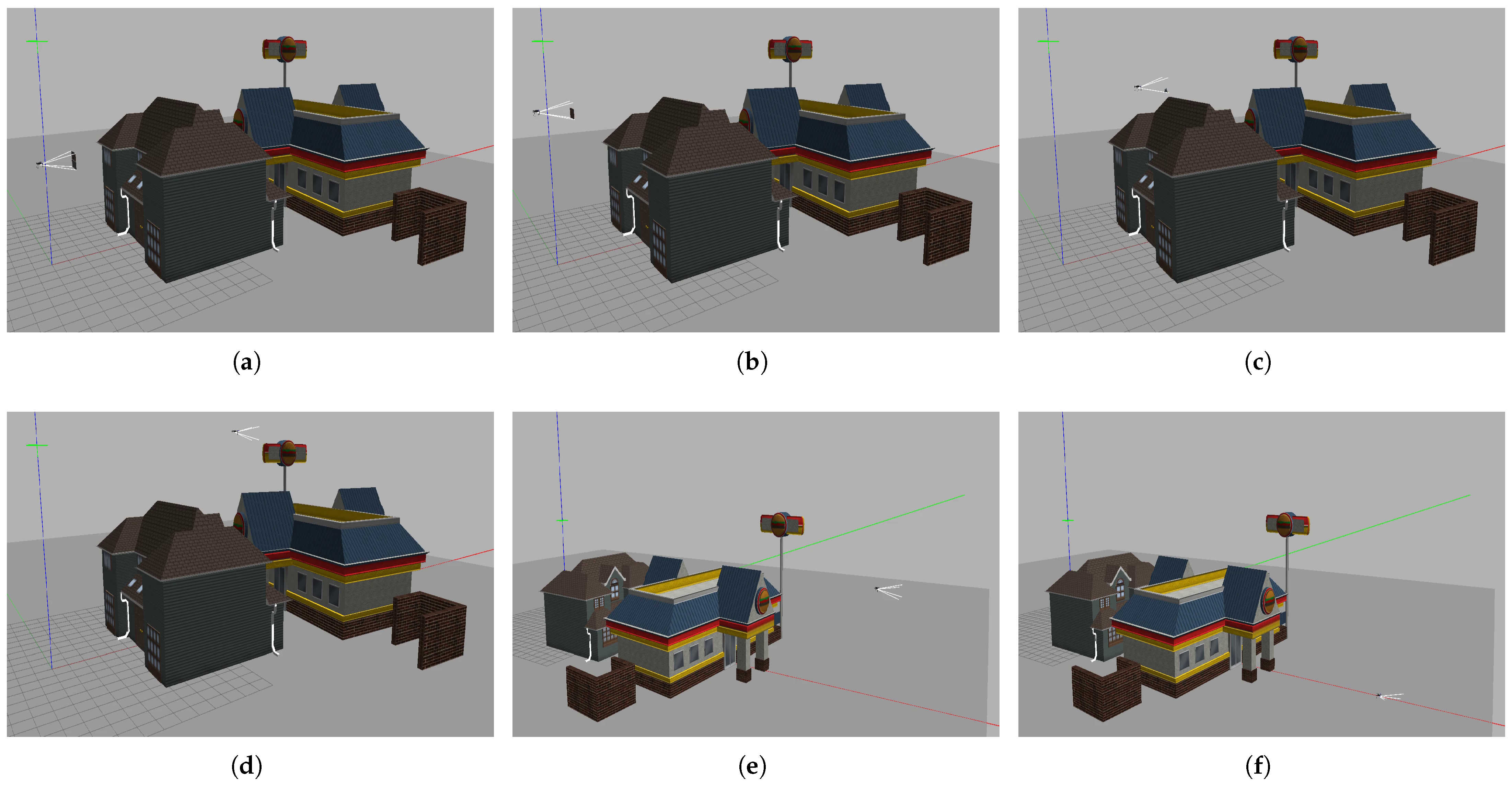
Figure 22.
The fourth experiment: The drone successfully flies over the buildings and arrives at its target roof. In image (a),the drone detects that the middle of the building is in its path, so it moves upward. In image (b), the drone detects that the top of the building is an obstacle, so it moves upward. In images (c,d), the drone passes over the buildings. In images (e,f), the drone reaches the target and lands on the ground.
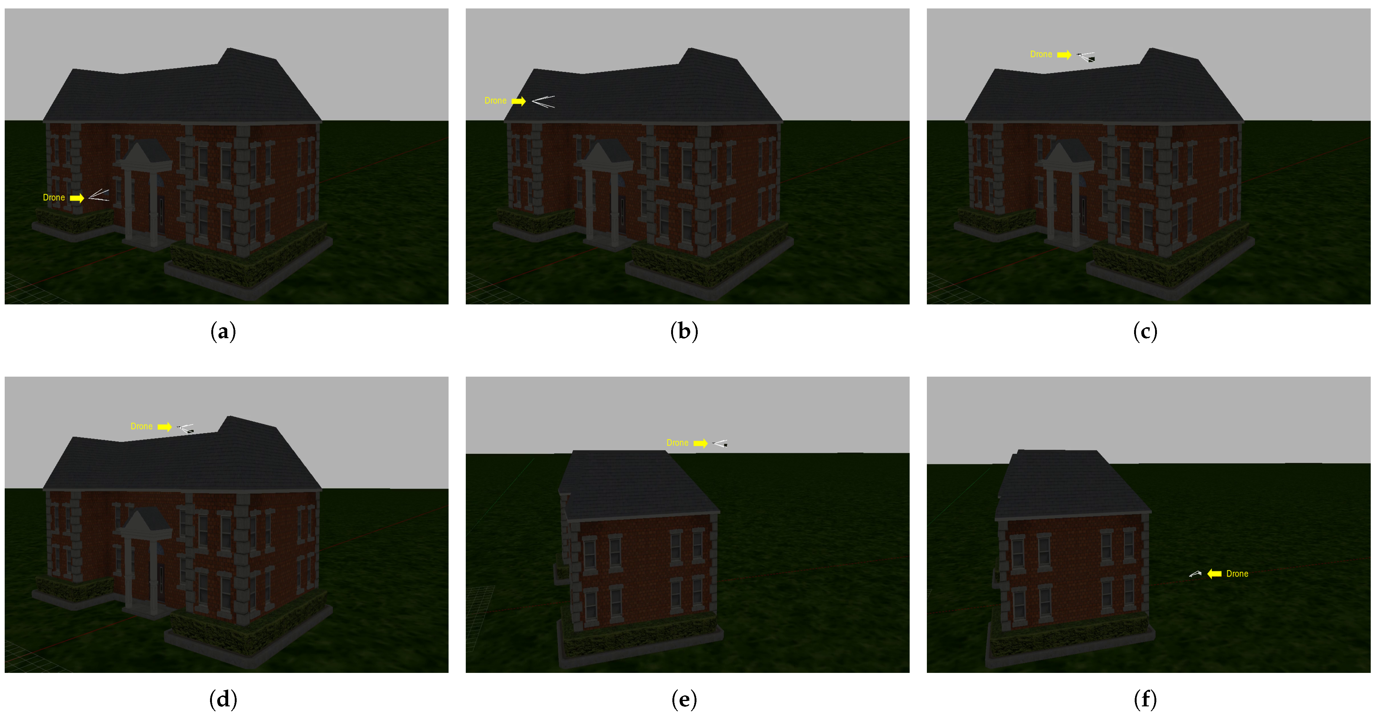
Figure 23.
The fifth experiment: The drone successfully flies over the school, navigates at night, and arrives at its target roof. In image (a), the drone detects that the middle of the school is in its path, so it moves upward. In image (b), the drone detects that the top of the school is an obstacle, so it moves upward. In images (c,d), the drone passes over the school. In images (e,f), the drone reaches the target and lands on the ground.
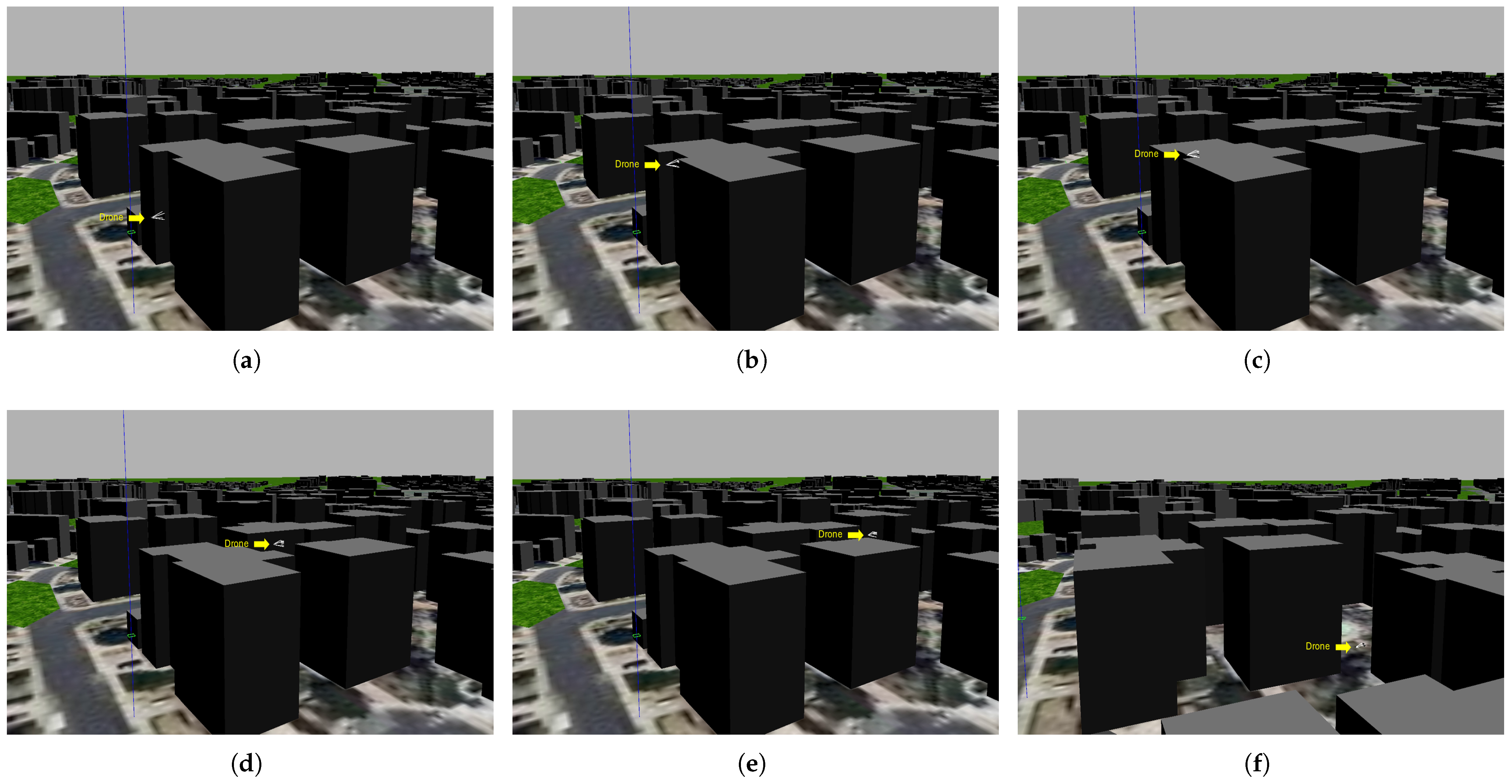
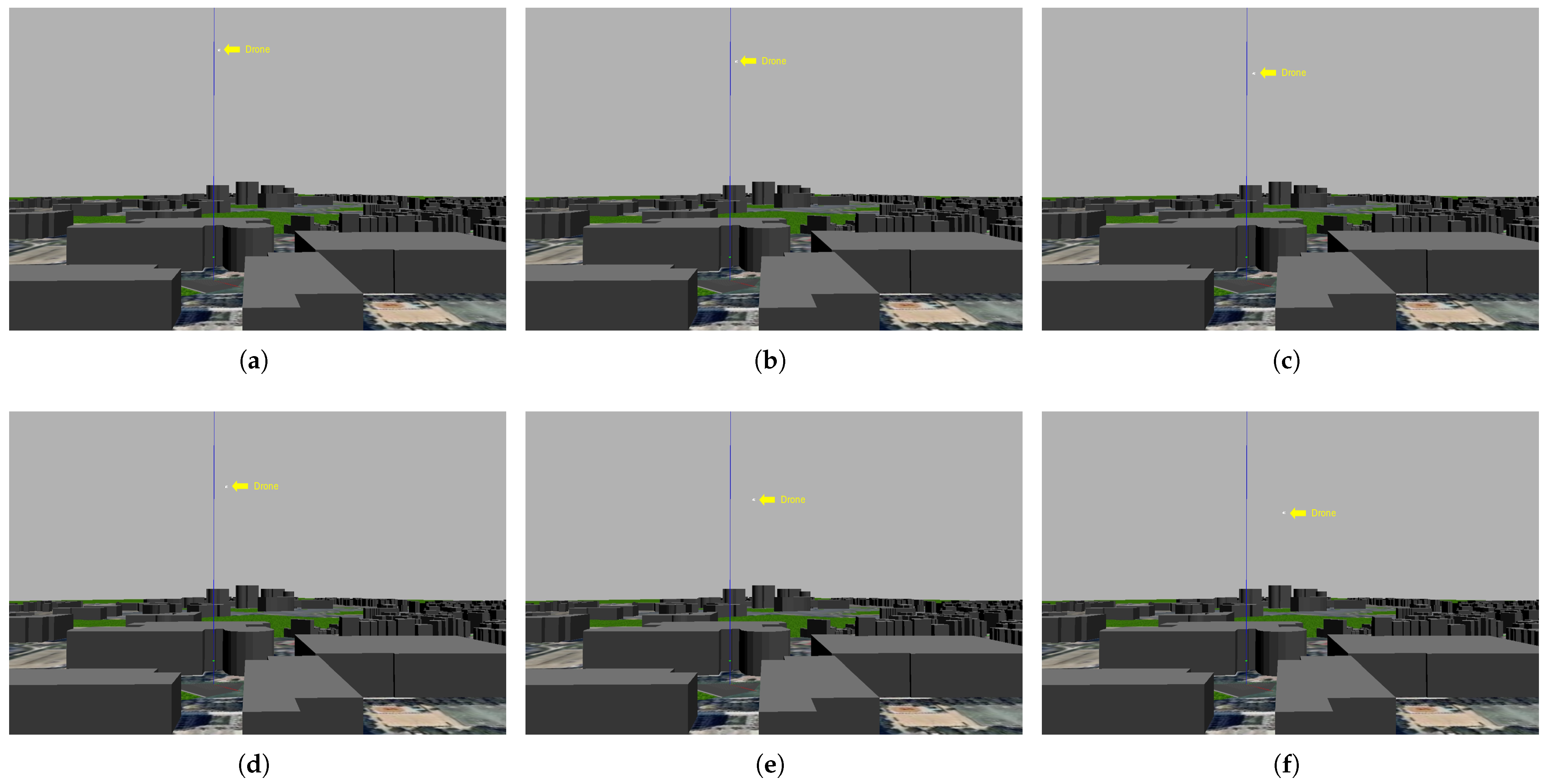
Figure 24.
The sixth experiment: The drone successfully flies over the buildings of the city and arrives at its target. In image (a), the drone detects that the middle of building is in its path, so it moves upward. In image (b), the drone detects that the top of the building is an obstacle, so it moves upward. In images (c–e), the drone passes over the school. In image (f), the drone reaches the target and lands on the ground.
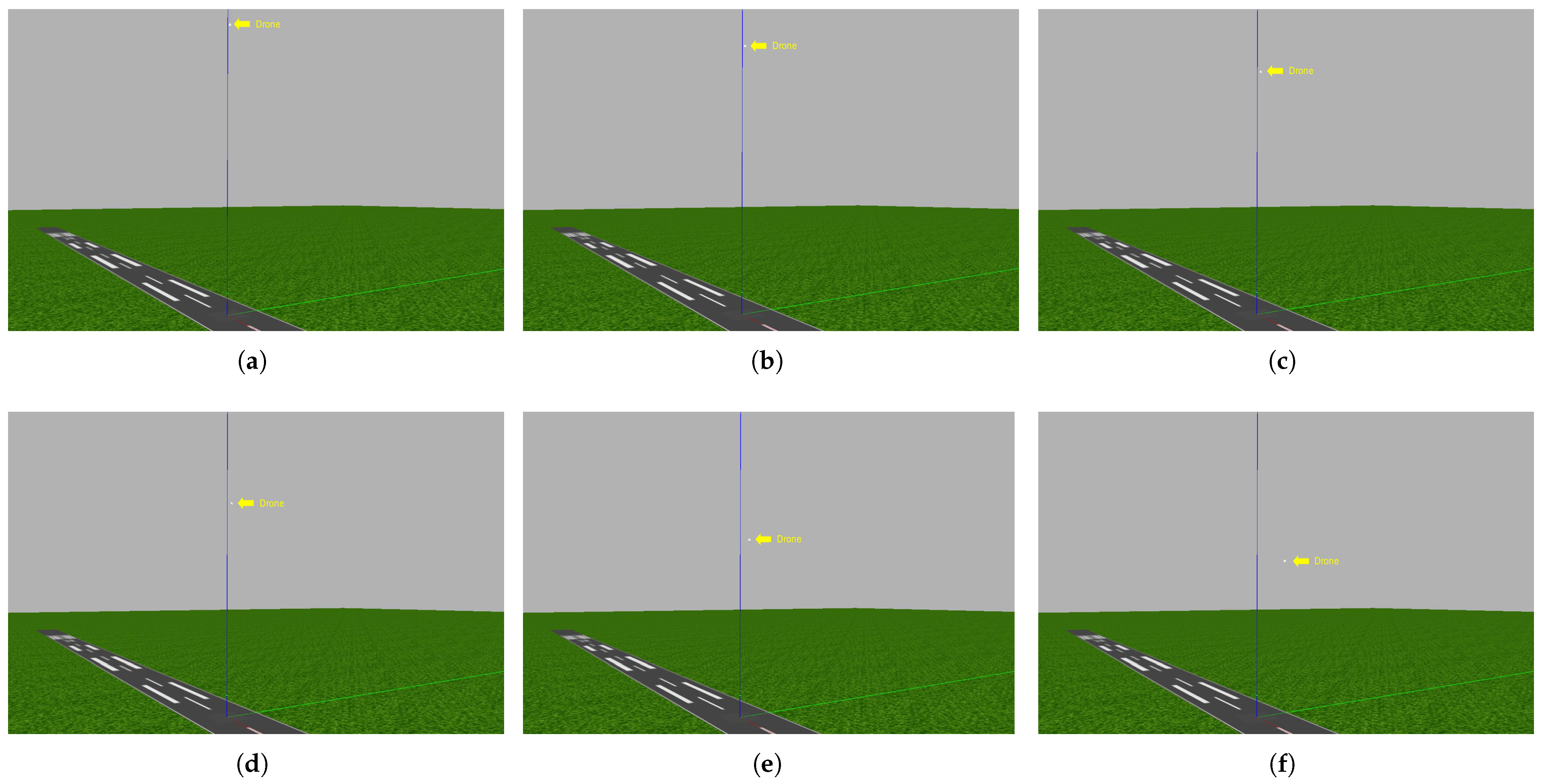
Figure 25.
The seventh experiment: The drone succeeds in lowering its altitude due to its awareness of the horizon. In image (a), the drone reaches an altitude of 100 m. In image (b), the algorithm lowers the drone’s altitude to 95 m due to the view of the horizon. In image (c), the algorithm lowers the drone’s altitude to 91 m due to the view of the horizon. In image (d), the algorithm lowers the drone’s altitude to 82 m due to the view of the horizon. In image (e), at an altitude of 76 m, the drone begins to head toward its target. In image (f), at an altitude of 69 m, the drone reaches the target.
Figure 26.
The eighth experiment: The drone succeeds in lowering its altitude due to its awareness of the horizon. In image (a), the drone reaches an altitude of 100 m. In image (b), the algorithm lowers the drone’s altitude to 95 m due to the view of the horizon. In image (c), the algorithm lowers the drone’s altitude to 91 m due to the view of the horizon. In image (d), the algorithm lowers the drone’s altitude to 82 m due to the view of the horizon. In image (e), at an altitude of 76 m, the drone begins to head toward its target. In image (f), at an altitude of 67 m, the drone reaches the target.
Figure 27.
The ninth experiment: The drone succeeds in lowering its altitude due to its awareness of the horizon. Image (a), the drone reaches an altitude of 150 m. In image (b), the algorithm lowers the drone’s altitude to 130 m due to the view of the horizon. In image (c), the algorithm lowers the drone’s altitude to 110 m due to the view of the horizon. In image (d), the algorithm lowers the drone’s altitude to 90 m due to the view of the horizon. In image (e), at an altitude of 76 m, the drone begins to head toward its target. in image (f), at an altitude of 69 m, the drone reaches the target.
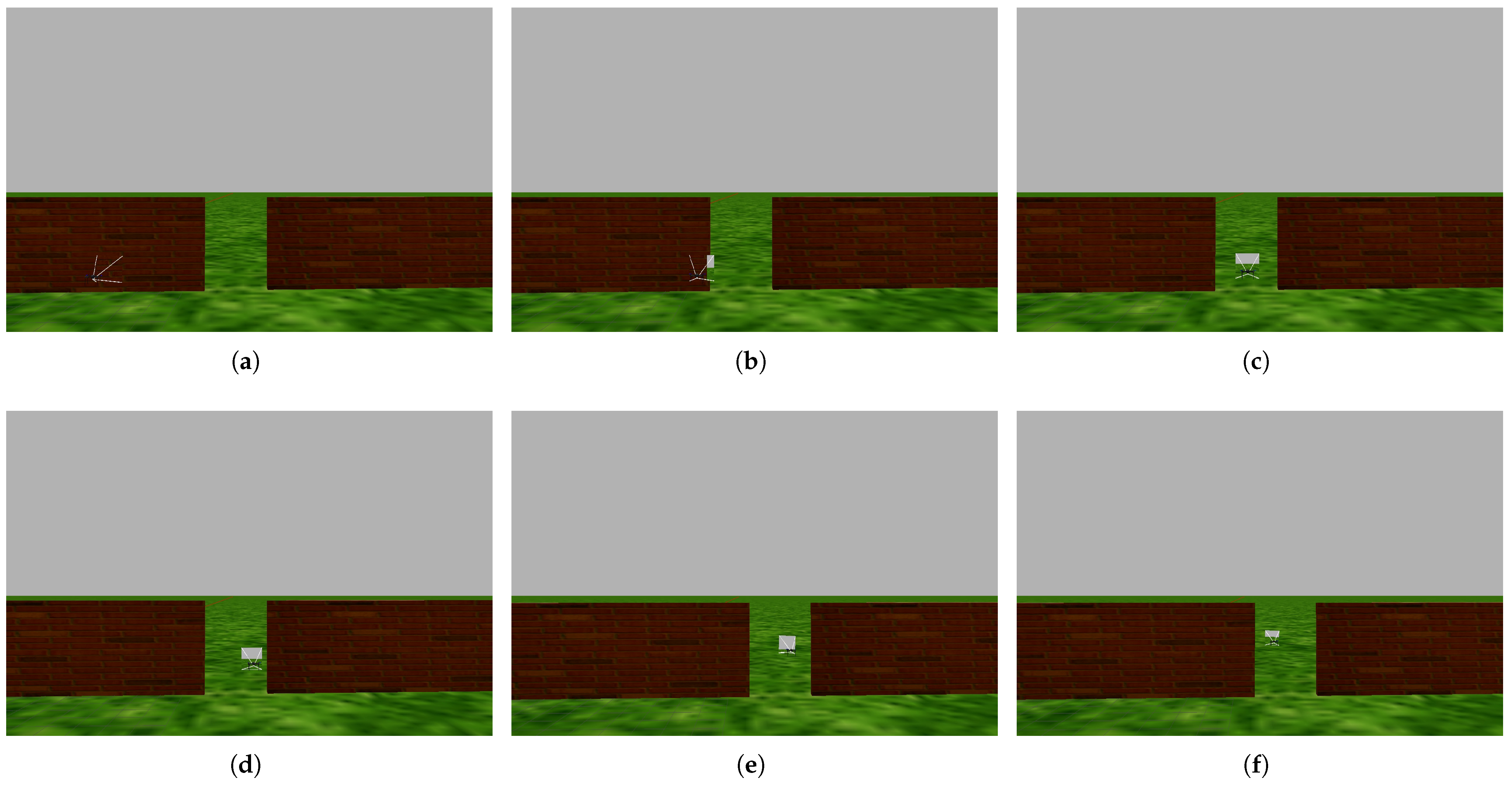
Figure 28.
The tenth experiment: The drone successfully avoids collisions with obstacles by flying alongside them and passing through a narrow gap. In images (a,b), the drone detects the obstacle and turns right. In image (c), the drone detects that there is a narrow gap through which it can pass. In images (d,e), the drone passes through the narrow gap to reach the target. In image (f), the drone reaches the target, which is 15 m away from the launch point.
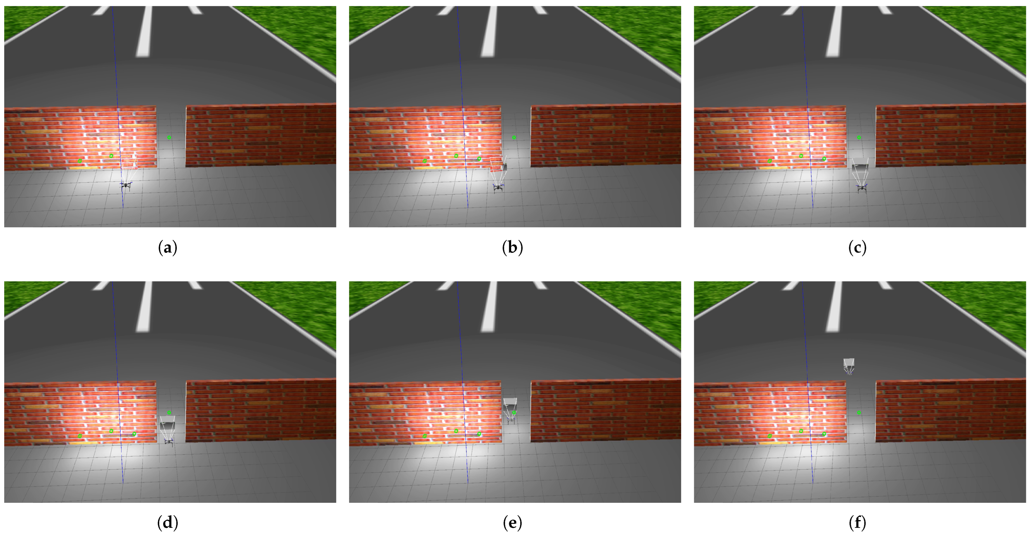
Figure 29.
The eleventh experiment: The drone successfully avoids collision with obstacles by flying alongside them and passing through a narrow gap despite the brightness of the scene. In images (a,b), the drone detects the obstacle and turns right. In image (c), the drone detects that there is a narrow gap through which it can pass. In images (d,e), the drone passes through the narrow gap to reach the target. In image (f), the drone reaches the target, which is 15 m away from the launch point.
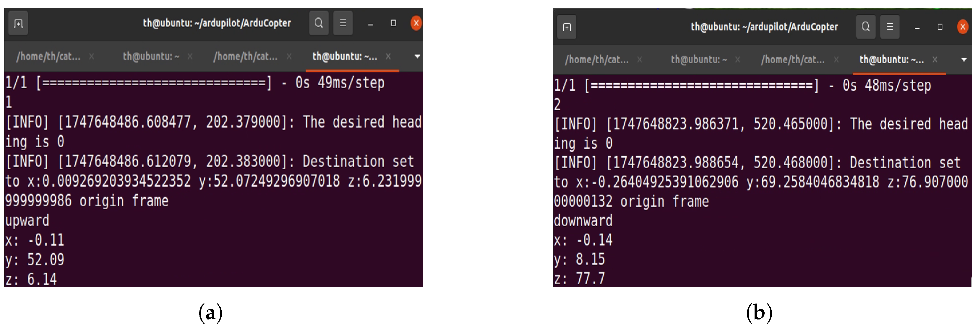
Figure 30.
The results of implementation of the algorithms used in our experiments. In image (a), after implementing Algorithm 2, the CNN prediction result is 1, indicating that the CNN detected an obstacle; thus, the drone moved upward. It traveled a distance of y = 52.09 m, and its altitude was z = 6.14 m. In image (b), after implementing Algorithm 3, the CNN prediction result is 2, which means that the CNN detected a horizon, and therefore, the drone moved downward. It traveled a distance of y = 8.15 m, and its altitude was z = 77.7 m.
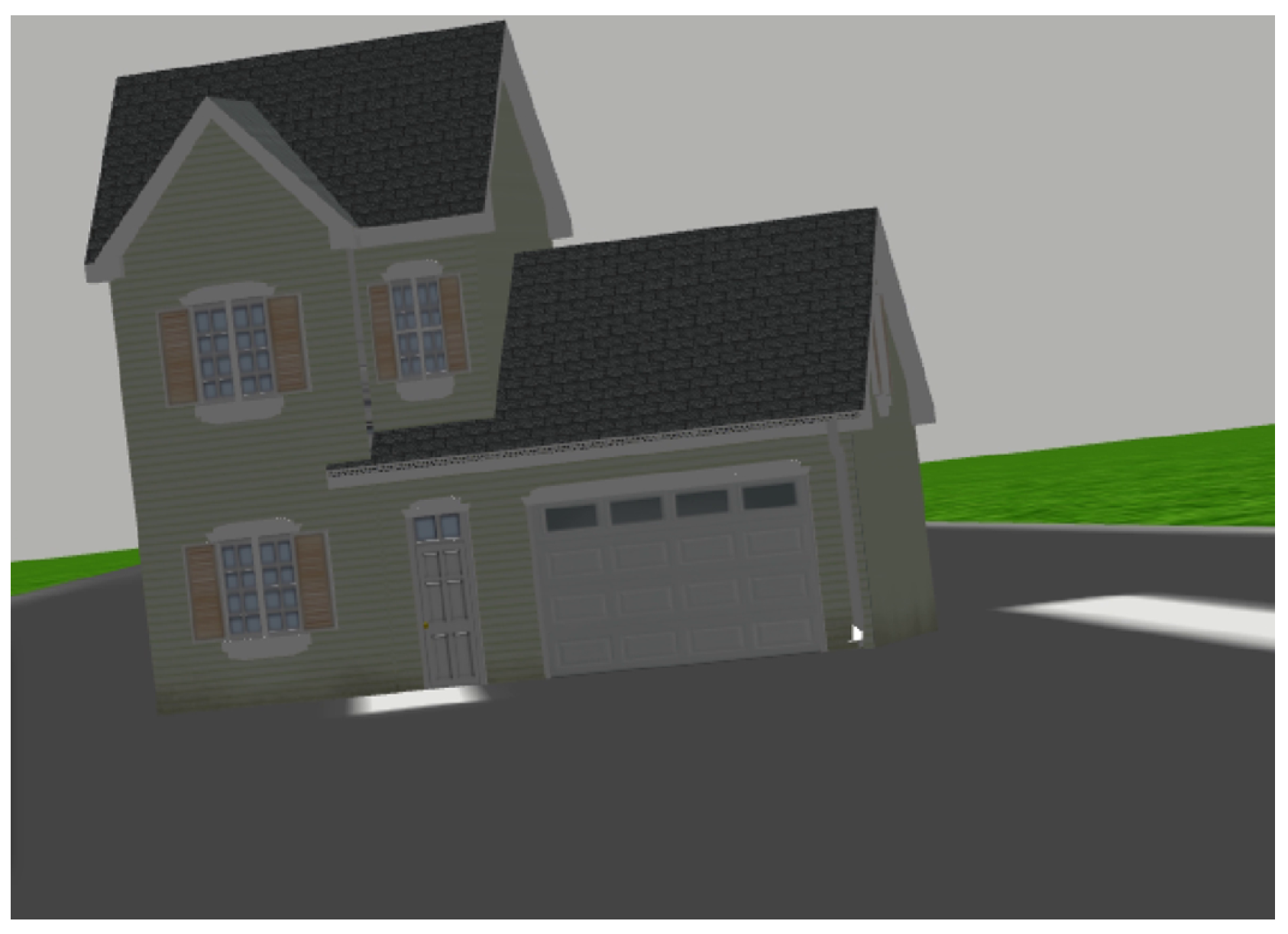
Figure 31.
The image captured by the drone’s camera while the drone rotated around its roll axis.
Figure 31.
The image captured by the drone’s camera while the drone rotated around its roll axis.
Table 1.
The comparison of databases used in drone navigation in terms of the environment and labeling.
Table 1.
The comparison of databases used in drone navigation in terms of the environment and labeling.
| Reference | Dataset | Environment | Navigation | Labels |
|---|
| [13] | HDIN | Inside buildings | 2D | Forward speed and steering control |
| [14] | Collision-sequence | Road of cars | 2D | On collisions and non-collisions |
| [15] | KITTI | Road of cars | 2D | Object detection |
| [22] | NYU | Inside buildings | 2D | Segmenting images into regions that correspond to individual objects |
| [23] | ICL | Inside buildings | 2D | Left, right, and forward |
| [24] | - - - | Inside buildings | 2D | Collision distance for each image |
| [25] | - - - | Inside buildings | 2D | Predict steering angle |
| [26] | SAIC | Road of cars | 2D | Determine speed and steering angle |
| [27] | Udacity | Road of cars | 2D | Predict steering angles |
| [28] | Comma2k19 | Road of cars | 2D | Position and orientation |
| [29] | ApolloScape | Road of cars | 2D | Labeling for lane detection, trajectory prediction, object detection |
| [30] | DDAD | Road of cars | 2D | Predict monocular depth of scene |
| Our dataset | - - - | Outdoor | 3D | No obstacles, obstacles, and the horizon |
Table 2.
The results of the experiments in terms of the type of obstacle, obstacle height, maximum drone altitude, and distance to target.
Table 2.
The results of the experiments in terms of the type of obstacle, obstacle height, maximum drone altitude, and distance to target.
| Experiment | Obstacle Type | Obstacle Height | Maximum Altitude of Drone | Distance to Target |
|---|
| 1 | bus | 4.5 m | 5 m | 6 m |
| 2 | Trees | 7 m | 7.5 m | 16 m |
| 3 | Building | 7.5 m | 8.5 m | 13 m |
| 4 | Buildings | 9 m | 11 m | 40 m |
| 5 | School | 15 m | 15.5 m | 30 m |
| 6 | City | 18.5 m | 19.5 m | 60 m |
Table 3.
The horizon view evaluation experiments focused on three key metrics: attaining the required altitude, lowering altitude, and reaching the target.
Table 3.
The horizon view evaluation experiments focused on three key metrics: attaining the required altitude, lowering altitude, and reaching the target.
| Experiment | Takeoff to Altitude | Descend to an Altitude | Reaching the Target at Altitude |
|---|
| 7 | 100 m | 76 m | 67 m |
| 8 | 100 m | 76 m | 69 m |
| 9 | 150 m | 76 m | 69 m |
Table 4.
The results of the evaluation of flying alongside an obstacle and the brightness evaluation in terms of the type of obstacle and the distance to the target.
Table 4.
The results of the evaluation of flying alongside an obstacle and the brightness evaluation in terms of the type of obstacle and the distance to the target.
| Experiment | First Obstacle | Second Obstacle | Distance to Target |
|---|
| 10 | Narrow gap | Walls | 15 m |
Table 5.
The results of the brightness evaluation and navigation at night.
Table 5.
The results of the brightness evaluation and navigation at night.
| Experiment | Obstacle | Lighting Conditions | Distance to Target |
|---|
| 5 | School | Navigation at nigh | 30 m |
| 11 | Narrow gap | Brightness | 15 m |


