Article

Hierarchical Reinforcement Learning for Viewpoint Planning with Scalable Precision in UAV Inspection

1
School of Control and Computer Engineering, North China Electric Power University, Beijing 102206, China
2
Institute of Disaster Prevention, Xueyuan Street, Yanjiao High Tech ZONE, Sanhe 065201, China
*
Author to whom correspondence should be addressed.
Drones 2025, 9(5), 352; https://doi.org/10.3390/drones9050352
Submission received: 20 March 2025 / Revised: 26 April 2025 / Accepted: 1 May 2025 / Published: 5 May 2025

Abstract

:
Viewpoint planning is crucial to ensure both inspection efficiency and observation precision in UAV inspection tasks. To address the issues of excessive waypoints and inadequate observation precision in traditional methods, this paper proposes a hierarchical reinforcement learning-based viewpoint planning method. The proposed method decomposes the viewpoint planning task into a high-level waypoint planning strategy and a low-level pose and zoom planning strategy. Additionally, a reward function is designed to enhance inspection precision, enabling collaborative optimization of waypoint positions, viewpoint poses, and focal lengths. Experimental results show that, compared with the classic coverage path planning method and non-hierarchical reinforcement learning approaches, the proposed method reduces the number of waypoints by at least 70% across multiple inspection objects. Furthermore, experiments with viewpoint planning at different precision levels demonstrate that the proposed method achieves scalable precision during inspection, with the observation resolution improving to 1.51 pixels/mm. Finally, a qualitative comparison is made between the proposed method in this paper and other representative methods in viewpoint planning. These results effectively demonstrate the validity and superiority of the proposed method in improving both inspection task efficiency and observation precision.

1. Introduction

With the rapid advancement of UAV (Unmanned Aerial Vehicle) technology, the applications of UAVs in the field equipment inspection domain have received increasingly widespread attention. With high-resolution zoom cameras and various sensors, UAVs can efficiently capture 4-kilopixel or even 8-kilopixel images of target objects, providing high resolution and rich texture information for equipment maintenance. In order to capture the images during inspection tasks, current UAV inspection methods predominantly rely on pre-defined flight paths with waypoint-by-waypoint image capture. After the image is obtained, automatic or manual processing is carried out, and the results serve as essential evidence for decision-making in the evaluation of factors for long-term equipment maintenance and operation of the inspection targets.
Due to the large number of waypoints and the requirement to accurately collect data from the entire surface of the inspected object, it is necessary to strike a balance between efficiency and precision. Taking the inspection of complex structures, such as wind turbine blades, as an example, traditional methods require planning a large number of waypoints to ensure comprehensive observation of the object’s surface [1]. This study defines the ratio of the observed surface to the total surface area of the object as the coverage ratio. Increasing the coverage ratio often leads to prolonged flight durations and higher energy consumption for UAVs, thereby limiting the number of devices that can be inspected within a single takeoff and landing cycle and reducing overall inspection efficiency. Here, inspection efficiency refers specifically to the operational throughput determined by waypoint count: fewer waypoints shorten flight paths, reduce mission time and energy consumption, and thus allow more inspection tasks per takeoff–landing cycle. Moreover, the complex shapes of the inspection objects and the small size of the defects make it difficult to achieve clear observation of critical defects.
To address these challenges, this paper proposes a viewpoint planning method based on hierarchical reinforcement learning. The proposed method decomposes the viewpoint planning task into a high-level waypoint planning strategy and a low-level pose and zoom planning strategy. As a result, it can achieve coordinated optimization of waypoints, viewing poses, and focal lengths. By employing a multi-shot per waypoint strategy, the method increases the number of captures at a single waypoint and utilizes the pose and zoom planning strategy to dynamically adjust the camera’s viewing poses and focal lengths. This approach reduces the number of required waypoints while ensuring high-precision observation of inspection objects, thereby improving inspection efficiency and guaranteeing observation precision.
The main contributions of this paper are as follows.
(1)
A novel UAV viewpoint planning method is proposed. By leveraging hierarchical reinforcement learning, the viewpoint planning task is decomposed into high-level and low-level strategies.
(2)
A reward function designed to improve observation precision is proposed. Within the reinforcement learning framework, a reward function is constructed that comprehensively considers the precision of the observation, the coverage ratio, and the number of waypoints.
(3)
The effectiveness of the proposed method is validated. Experimental evaluations on various inspection object models demonstrate that the proposed method reduces the number of waypoints by at least 70% across multiple inspection tasks while increasing the average observation resolution to 1.51 pixels/mm, significantly enhancing the efficiency and precision of inspection tasks.

2. Related Work

To better illustrate the evolution and influence of existing methods in the viewpoint planning literature, we conducted a literature mapping analysis. Figure 1 visualizes key contributions, clearly indicating the temporal progression and citation impacts of various approaches. This mapping provides an overview of how different viewpoint planning strategies emerged and evolved, highlighting the importance and influence of seminal works.
Viewpoint planning for inspection and reconstruction has evolved along several complementary threads. Early efforts focused on fast, greedy selection of viewpoints, while subsequent research explored heuristic and continuous optimization techniques, and most recently, reinforcement learning has emerged as a powerful paradigm. In what follows, we first trace the chronological development of these methods, then examine their inter-relationships and categorize them by methodological families.

2.1. Greedy Algorithms

Among the earliest approaches to the Viewpoint Planning Problem (VPP) are greedy algorithms, which iteratively select the next viewpoint that maximally increases coverage. Seminal works such as [2,3,4,5,6,7] demonstrated that greedily chosen views can be computed extremely efficiently, making them attractive for large 3D models. However, because each choice optimizes only the immediate gain, these methods are prone to being trapped in locally optimal solutions, a shortcoming that is formally analyzed in [8]. Despite this, greedy strategies continue to serve as benchmarks and initialization steps for more complex planners.

2.2. Heuristic Algorithms

To overcome local optimal issues, researchers introduced population-based metaheuristics such as Genetic Algorithms (GA) and Particle Swarm Optimization (PSO) [9,10,11]. Comparative studies have shown that PSO often converges more reliably than GA in VPP instances, due to its balance of exploration and exploitation [12]. Nevertheless, both classes of methods remain highly sensitive to initialization and parameter tuning, as discussed in [13]. These heuristic approaches represent an important advance by allowing global search over complex, multimodal objective function space, but practical deployment requires careful calibration.

2.3. Differentiable Continuous Planning

More recently, a differentiable continuous multiple viewpoint planning algorithm was proposed. This method models the viewpoint planning problem as a cover set problem through a mathematical representation of continuous viewpoint sampling and solves it using a greedy search algorithm to obtain suitable viewpoints [14]. Nevertheless, this approach neglects zoom planning and thus cannot effectively guarantee the precision of defect observation.

2.4. Reinforcement Learning-Based Methods

Inspired by successes in robotics and game play, reinforcement learning (RL) has been applied to VPP to address the combinatorial explosion of possible view sequences. Early demonstrations [8,15] framed the VPP as a Markov Decision Process (MDP) and used Q-learning or policy-gradient methods to sequentially choose viewpoints [16] that maximize long-term coverage reward. Ser Nam Lim et al. [8] introduced a novel geometric scoring function for MDP states, while Wang et al. [17] incorporated lighting conditions into visibility metrics and employed Asynchronous Advantage Actor–Critic (A3C) to navigate the view space.
Peralta et al. [18] extended RL to “next-best-view” house-scanning by training Deep Q-Networks (DQN) and Deep Deterministic Policy Gradient (DDPG) [19,20] agents on synthetic 3D models. Christian Landgraf et al. [15] presented an end-to-end system combining CAD models and robot kinematics to learn high-quality poses for surface inspection. Wei Jing et al. [21] formulated online robotic arm coverage planning as an MDP and devised an RL-based search to generate inspection trajectories in real time.
On the algorithmic front, Maren Bennewitz et al. [22] used deep RL for next-best-view with RGB-D sensors, Gao et al. [23] introduced DPDQN to optimize UAV data acquisition routes, and Duan et al. [24] combined sequence prediction networks with Monte Carlo Tree Search to improve decision making and reward assignment in exploration tasks. Together, these works demonstrate the ability of RL to take advantage of historical interactions and long-horizon objectives, yet they also highlight challenges in stability and sample efficiency when high-dimensional decisions (waypoint, pose, zoom) are unified.

2.5. UAV Path and Coverage Planning

Parallel to model-centric VPP, several studies have addressed UAV-based path planning for inspection. Zhao et al. [25] surveyed the location of indoor UAVs and avoidance of obstacles for warehouse inventory, while Li et al. [26] proposed Quality-Efficiency Coupled Iterative Coverage Path Planning (QECI-CPP) to balance image quality and mission time in 3D inspection. Further advances include pre-flight data collection frameworks [27] and hybrid waypoint selection algorithms that adapt to GNSS shadowing [28].

2.6. Summary

In summary, while viewpoint planning problems involving zoom planning and multi-shot per waypoint strategies have not yet been explored, reinforcement learning presents a promising approach. However, single-layer reinforcement learning methods, which unify waypoint positions, viewpoint poses, and focal length into a single optimization model, face challenges such as a large number of dimensions and unstable training convergence. Furthermore, waypoint selection, viewpoint pose adjustment, and focal length optimization are tightly coupled decisions, making it difficult to simultaneously identify optimal solutions. Therefore, further research is required to address these challenges effectively.

3. Approach

3.1. Problem Formulation

The goal of viewpoint planning is to minimize the number of waypoints while ensuring full coverage of the inspected object’s surface and meeting the required observation precision. In UAV-based inspection tasks, the viewpoint planning problem involves determining optimal waypoint positions, as well as the corresponding viewpoint pose and focal length at each waypoint. The challenges associated with this problem are as follows.
(1)
Excessive number of waypoints. Traditional methods often require a large number of waypoints to achieve full coverage of the inspection object’s surface. This not only results in low inspection efficiency, but also increases task complexity and execution risks.
(2)
Ensuring observation precision. The surface of the inspected object may contain small defects, which can be difficult to detect in captured images if the observation precision is inadequate.
(3)
Complexity of viewpoint planning. Viewpoint planning is inherently complex due to the tightly coupled optimization of waypoint selection and camera pose and zoom value. The tightly coupled optimization leads to a combinatorial explosion in the decision space, making it an NP-hard problem.
To address the aforementioned challenges, this study proposes three strategies. First, to reduce the excessive number of waypoints, a multi-shot per waypoint strategy is adopted. This strategy captures multiple images at each predetermined position, thereby minimizing the number of waypoints required. Second, to ensure observation precision, a zoom planning strategy is introduced. By dynamically adjusting the camera’s focal length during viewpoint planning, this method ensures high-precision observation of the inspection object’s surface, effectively capturing small-scale defects. An illustration of the multi-shot per waypoint and zoom planning strategies for UAVs is shown in Figure 2, where blue boxes represent the coverage areas of multiple captures, while yellow boxes of varying sizes indicate the different focal lengths used during shooting. Third, to address the challenge of the complexity of viewpoint planning problem, a hierarchical reinforcement learning approach is employed. The viewpoint planning task is decomposed into high-level and low-level strategies. Using hierarchical strategy learning and optimization, the problem is decoupled.
To this end, this study proposes a viewpoint planning method based on hierarchical reinforcement learning, denoted as HRL-SPVP (Hierarchical Reinforcement Learning for Scalable Precision Viewpoint Planning). The proposed algorithm comprises two primary stages: visibility modeling and viewpoint optimization, as depicted in Figure 3. In the visibility modeling stage, the inspection object’s 3D model is preprocessed using an Isotropic Explicit Remeshing (IER) method [29], which reconstructs and remeshes the original model. This preprocessing step facilitates subsequent visibility calculations and simplifies the determination of the inspection object’s surface area. A set of candidate viewpoints is then sampled in space and their visibility relative to the surface of the inspection object is computed. In the viewpoint optimization stage, the visibility information obtained is utilized to optimize viewpoint selection, aiming for complete surface coverage and high-precision observation of the object. To meet the objectives of complete coverage, observation precision, and waypoint minimization, the viewpoint planning problem is framed as an optimization task. Hierarchical reinforcement learning decomposes the viewpoint planning process into two levels: high-level waypoint planning and low-level pose and zoom planning. This approach effectively decouples the complex interdependencies between waypoint position, viewpoint poses, and focal lengths. The high-level waypoint planning strategy selects the optimal waypoint positions from the candidate set to ensure full surface coverage with minimal waypoints, while the low-level pose and zoom planning strategy fine-tunes the viewpoint poses and focal lengths at each waypoint to satisfy the required observation precision.

3.2. Visibility Modeling

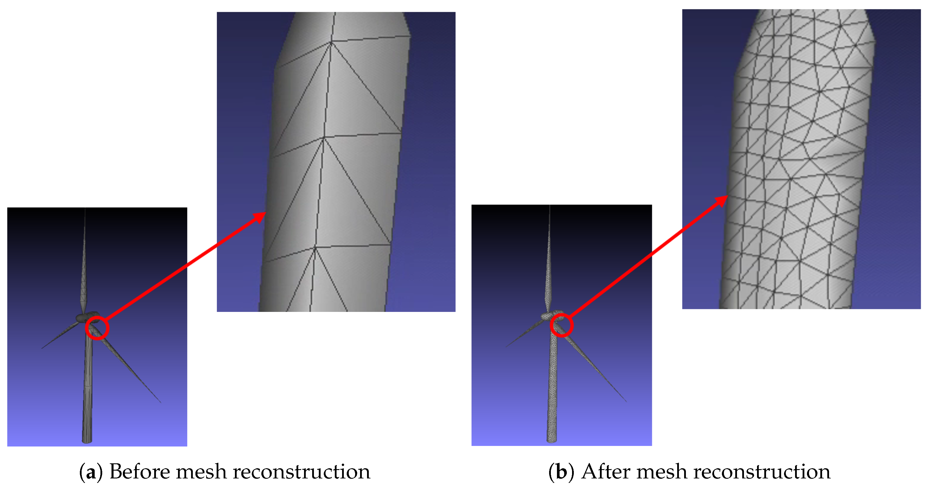
3.2.1. Remeshing of Inspection Targets

In the visibility modeling process, this study employs the IER (Isotropic Explicit Remeshing) method to remesh the model, achieving a uniform distribution of surface meshes with consistent mesh shape and area. This not only establishes the foundation for subsequent visibility calculations, but also simplifies the computation of the inspection object’s surface coverage area. An example of the model before and after mesh reconstruction is shown in Figure 4.

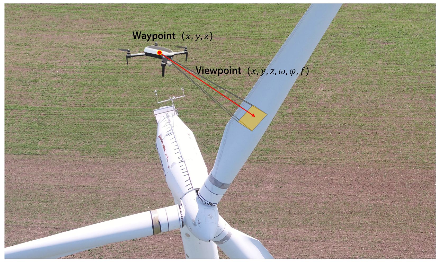
3.2.2. Viewpoint Sampling

To generate a set of candidate viewpoints in the flight space, sampling of waypoint positions, viewpoint pose, and focal lengths is necessary. A viewpoint is represented as a 6-degree-of-freedom vector v = [ x , y , z , ω , φ , f ] , where the components include the spatial position of the UAV, i.e., waypoint position ( x , y , z ) ; the pose of the UAV’s gimbal(viewpoint pose), including the yaw angle ω , the pitch angle φ ; the camera focal length f. In this study, the roll angle is not explicitly considered as a degree of freedom because a roll-stabilized gimbal is mounted on the UAV. Roll stabilization is implemented using a PID control algorithm, which automatically maintains the horizontal axis of the captured images parallel to the ground plane. The roll stabilization tolerance does not affect the viewpoint planning results. A schematic of waypoints and viewpoints is shown in Figure 5.
First, uniformly distributed candidate waypoints are generated in the surrounding space of the inspection object. In this study, random sampling is conducted in the region around the inspection object. After obtaining the initial set of candidate waypoints, collision detection is performed to ensure that the distance between each waypoint and the surface of the inspection object is greater than the minimum safety distance d m i n . The waypoint sampling results after collision detection are shown in Figure 6.
In this study, random sampling is specifically selected for generating candidate waypoints. Random sampling allows a wider exploration of the feasible region, offering greater flexibility and enhancing the likelihood of identifying superior viewpoints suitable for complex and practical UAV inspection scenarios.
The viewpoint poses are then determined at the candidate waypoints. The viewpoint pose consists of the yaw angle ω and the pitch angle φ . The range of the yaw angle is set as [ 0 , 2 π ) , and it is discretized at fixed angular intervals Δ ω resulting in a discrete set of angles:
Ω = { ω i ω i = j Δ ω , j = 0 , 1 , , N ω 1 }
Here, N ω = 2 π Δ ω represents the number of discrete yaw angles.
Based on the gimbal pitch angle limitation range [ φ m i n , φ m a x ] , discretization is performed using a fixed angular interval Δ φ , resulting in a set of discrete pitch angles.
Φ = { φ j φ j = φ m i n + j Δ φ , j = 0 , 1 , , N φ }
Here, N φ = φ m a x φ m i n Δ φ represents the number of discrete pitch angles.
Subsequently, the set of focal lengths for image capture at the viewpoint poses is determined. The selection of focal lengths influences the camera’s field of view and imaging resolution. The focal length range is set as [ f m i n , f m a x ] , and discretized at fixed intervals of Δ f , resulting in the focal length set:
F = { f k f k = 2 k × f m i n , k = 0 , 1 , , N f }
Here, N f = log 2 f m a x f m i n represents the number of discrete focal lengths.
Finally, the set of candidate viewpoints V is constructed, with each viewpoint consisting of a waypoint position, viewpoint pose, and focal length:
V = ( x i , y i , z i , ω j , φ j , f k ) ( x i , y i , z i ) P , ω j Ω , φ j Φ , f k F
where P is the set of waypoint positions that satisfy the collision-free condition. Ω , Φ , and F are the sets of discrete yaw angles, pitch angles, and focal lengths, respectively.

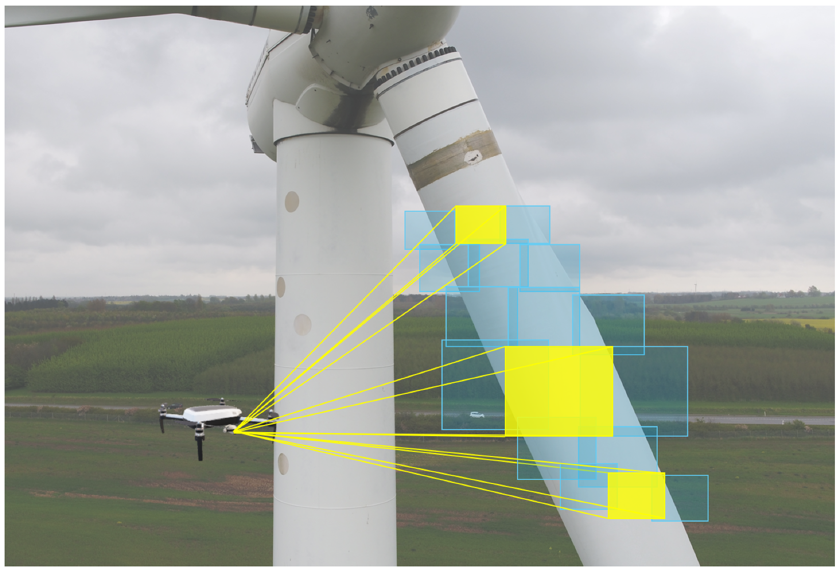
3.2.3. SubsubsectionVisibility Computation Between Viewpoints and Surface Grids

To facilitate efficient visibility queries during viewpoint planning, a visibility matrix is precomputed based on the sampled waypoints, viewpoint poses, and focal lengths. The objective of the visibility computation is to determine the relationship between a given viewpoint and the surface grids of the object, accounting for the following key factors:
  • Field of View (FOV) Constraint: Determines whether a grid lies within the camera’s field of view.
  • Incidence Angle Constraint: Evaluates the angle between the direction of the view and the grid surface norm, ensuring that it does not exceed a predefined threshold θ max .
  • Occlusion Detection: Verifies the absence of obstructions along the line of sight between the viewpoint and the center of the grid, ensuring that no other grids block visibility.
  • Mesh orientation: whether the surface norm of the triangular mesh is oriented toward the camera.
To improve computational efficiency, the visibility matrix G is constructed offline. This binary matrix encodes the visibility relationships between all candidate viewpoints and surface grids. Given a candidate viewpoint set V = { v 1 , v 2 , , v N } and a surface grid set M = { m 1 , m 2 , , m N } , the visibility matrix G is defined as:
G i , j = 1 , If the mesh m j is visible under the viewpoint v i 0 , else

3.3. Hierarchical Reinforcement Learning-Based Viewpoint Planning

The scalable precision viewpoint planning problem studied in this paper aims to minimize the number of waypoints while ensuring full coverage of the inspection object’s surface and maintaining observation precision. To address this, a hierarchical reinforcement learning (HRL) approach is adopted to model the viewpoint planning problem. The high-level and low-level strategies are defined as follows.
  • High-level waypoint planning strategy: Responsible for selecting the optimal waypoint position ( x , y , z ) from the set of candidate waypoints to achieve full surface coverage of the inspection target with as few waypoints as possible.
  • Low-level pose and zoom planning strategy: At a given waypoint, multiple image captures are performed to cover the local region. This strategy optimizes the viewpoint pose ( ω , φ ) and the focal length f to meet the precision requirements of inspection data acquisition.
The hierarchical formulation in this method is driven by the adoption of multi-shot per waypoint strategy, which alters the traditional viewpoint planning paradigm. Traditional methods generally assume a single capture at each waypoint, making waypoint selection and pose adjustment essentially independent. However, in our approach, each waypoint involves multiple captures with varying poses and focal lengths, enhancing coverage efficiency and reducing total waypoint count. Waypoint selection directly influences the subsequent pose and zoom selections at each waypoint: determining “where to observe” inherently affects decisions on “how to observe”.
In scenarios utilizing the multi-shot per waypoint strategy, hierarchical planning effectively mirrors the workflow of viewpoint planning. High-level waypoint planning determines which waypoint positions in 3D space are more optimal for observation, i.e., “where to observe”; and low-level pose and zoom planning determines the pose and focal length for multiple shots at each waypoint position, i.e., ‘how to observe’. Each waypoint position includes multiple viewpoints with different poses and corresponding focal lengths. Therefore, the two states of the waypoints and poses are not independent of each other in this viewpoint planning problem.
Moreover, the sequential generation of waypoint positions during the planning process also contributes to this interdependence. Due to the issues of visibility, coverage, and observation precision, the selection of a different waypoint position will affect the subsequent pose and focal length selections at that waypoint position. Likewise, the pose and focal length selections at the currently selected waypoint position will also affect the next waypoint position selection.
By employing a hierarchical approach, the high-dimensional viewpoint planning problem is decomposed into two lower-dimensional subproblems, effectively reducing the complexity of the original problem. Furthermore, the hierarchical structure better captures the layered dependency relationships between waypoint planning, viewpoint pose planning, and zoom planning. This facilitates strategy learning and optimization, enabling the model to independently learn more sophisticated strategies within each hierarchical level.

3.3.1. High-Level Waypoint Position Planning

In the hierarchical reinforcement learning framework, waypoint planning is responsible for selecting the appropriate waypoints of the candidate set using high-level policy to achieve full surface coverage of the inspection target with as few waypoints as possible. Since each action in the high-level policy may take an indefinite number of time steps, it is modeled as a Semi-Markov Decision Process (Semi-MDP, SMDP).
  • State Space: The state S t H of the high-level strategy includes the set of covered meshes M c t , the set of remaining uncovered meshes M u c t , and the sequence of selected waypoint positions P t .
  • Action Space: The action A t H of the high-level strategy is to select a new waypoint position p t from the candidate waypoint set P, where:
    A t H { p t p t P P t }
  • State Transition: After executing the high-level action A t H , the low-level strategy begins to execute at the selected waypoint position p t for a duration of time step τ t . Upon completion of the low-level strategy, the high-level state transitions to:
    S t + τ t H = M c t + τ t , M u c t + τ t , P t + τ t
    where:
    M c t + τ t = M c t M c τ t
    M c τ t is the new set of covered grids added by the low-level policy at the current waypoint.
    M u c t + τ t = M u c t M c τ t
    P t + τ t = P t { p t }
  • Policy Learning: The high-level policy is trained using the SMDP Q-learning algorithm, with the update rule:
    Q H ( S t H , A t H ) Q H ( S t H , A t H ) + η R t H + γ τ max A Q H ( S t + τ H , A ) Q H ( S t H , A t H )
    where η is the learning rate and γ is the discount factor.

3.3.2. Low-Level Pose and Zoom Planning

The low-level strategy performs multiple image captures at a given waypoint, planning the viewpoint pose and the focal length for each capture to achieve effective coverage of the local region, thereby meeting the observation precision requirements for inspection data collection. The low-level strategy makes decisions within a fixed time step, and the state transitions exhibit the Markov property, making it suitable for modeling as a Markov Decision Process (MDP).
  • State Space: The state of the low-level policy S t L includes the set of covered meshes M c τ t , t at the current waypoint, the set of meshes that are visible but not yet covered M u c τ t , t at the current waypoint, and the set of selected viewpoint combinations V s , t at the current waypoint.
  • Action Space: During the visibility modeling phase, the viewpoint parameters are discretized. The action A of the low-level policy involves selecting a new viewpoint combination ( ω , φ , f ) from the discretized set of poses and focal lengths at the current waypoint ( ω , φ , f ) :
    A t L ( ω j , φ j , f k ) ( ω j , φ j , f k ) V candidate V s , t
    Here, V candidate is the set of selectable viewpoint combinations at the current waypoint.
  • State Transition: After executing a low-level action A t L , a capture is performed, and the state is updated as follows:
    M c τ t , t + 1 = M c τ t , t M new t M u c τ t , t + 1 = M u c τ t , t M new t V s , t + 1 = V s , t { A t L }
    Here, M new t represents the set of newly covered grid cells captured by the selected viewpoint at time t.
  • Termination Condition: The low-level strategy terminates when either local full coverage is achieved or the maximum number of time steps is reached. Local full coverage is defined as the complete coverage of all visible grid cells at the current waypoint, while the maximum time step constraint corresponds to the predefined maximum number of captures allowed at a single waypoint.
  • Policy Learning: The low-level strategy is trained using the Q-learning algorithm, with the update rule given as:
    Q L ( S t L , A t L ) Q L ( S t L , A t L ) + η R t L + γ max A Q L ( S t + 1 L , A ) Q L ( S t L , A t L )
    where η is the learning rate and γ is the discount factor.

3.3.3. Reward Function Design

To achieve collaborative optimization between the high-level and low-level strategies, this work designs a unified reward function that includes coverage reward, waypoint penalty, and observation precision reward or penalty. The overall reward function is expressed as:
R = α × Δ S c S total β + R pre
where:
α :
Coverage reward coefficient, controlling the weight of this component in the total reward.
Δ S c :
Newly covered grid area by the current viewpoint, i.e., the area of grids visible from the current viewpoint that have not been covered by any previous viewpoints.
S total :
Total surface area of the inspection object. In the calculation process, a specific numerical value for S total is not required because only the coverage ratio needs to be calculated in this study. After remeshing, the coverage ratio can be determined by the ratio of the number of newly added covered grids to the total number of surface grids.
β :
Waypoint penalty coefficient, representing the fixed penalty incurred for adding one more waypoint.
R pre :
Observation precision reward term.
The components of the reward function are defined and computed as follows.
  • Coverage Reward: The coverage reward guides the algorithm to select better viewpoints, thereby achieving more comprehensive coverage of the surface meshes, and is defined as:
    R c = α × Δ S c S total
  • Waypoint Penalty: The waypoint penalty aims to encourage the agent to achieve full coverage with as few waypoints as possible. A fixed negative reward is applied for each additional waypoint. The waypoint penalty is defined as:
    R w p = β
  • Observation Precision Reward: The observation precision reward guides the algorithm to select viewpoints that meet the observation precision requirements. Specifically, the number of pixels corresponding to a texture of size d mm on the surface of the inspection object in the camera imaging plane should not be less than the predefined value D.
First, utilizing the perspective projection model in computer vision, the size of the texture on the imaging plane can be calculated to determine whether the observation precision requirement is satisfied. Let the actual size of the texture on the inspection object’s surface be d mm, located at a distance of Z mm from the camera’s optical center, with a camera focal length of f mm and a sensor pixel size of s mm/pixel. According to the principles of perspective projection, the projected size of the texture d on the imaging plane is:
d = f Z × d × cos θ
Here, θ is the angle between the viewpoint pose direction and the surface norm of the grid, i.e., the incidence angle. Taking into account the influence of the incidence angle, the effective size of the defect in the imaging plane decreases due to tilt, requiring a correction factor of cos θ . The number of pixels n that correspond to the texture in the imaging plane is:
n = d s = f × d × cos θ Z × s
When n D , the surface mesh at the current focal length is considered to meet the observation precision requirement. As shown in Equation (20), for smaller texture sizes or surface meshes located further from the camera, setting a larger focal length increases the number of pixels corresponding to the texture size, making it easier to satisfy the observation precision requirement.
Next, the proportion of grids not meeting the observation precision requirement under the current viewpoint is calculated as P v p i u q :
P v p i u q = N v p i u q N v p i
where N v p i u q represents the number of visible meshes that do not meet the observation precision requirement, and N v p i denotes the total number of visible meshes under the current viewpoint.
Subsequently, the observation precision reward R pre is calculated based on P v p i u q as:
R pre = + δ , If P v p i u q = 0 δ × P u q , If P v p i u q > 0
Here, δ is the observation precision reward coefficient, which determines the weight of this term in the overall reward. When all visible grids meet the observation precision requirement, a positive reward + δ is given. Otherwise, a negative reward is applied in proportion to the ratio of grids not meeting the precision requirement, with higher ratios incurring greater penalties.
Using a unified reward function to jointly train the high-level and low-level strategies, this approach achieves coordinated optimization between the two levels, enhancing overall performance. After selecting a new waypoint, the high-level strategy immediately incurs a waypoint penalty of β . Once the low-level strategy completes the execution at the selected waypoint, the high-level strategy receives the cumulative rewards from the coverage reward R c and the observation precision reward R pre . Thus, the total reward R H for the high-level strategy includes both the waypoint penalty and the cumulative rewards of the low-level strategy.
The low-level strategy receives immediate rewards R L after each selection of a viewpoint, which are used to update the Q values of the low-level policy. This design ensures that when the high-level strategy selects waypoints, it considers the cumulative rewards obtained after the execution of the low-level strategy, enabling the selection of waypoints that maximize overall utility. Meanwhile, at each waypoint, the low-level policy optimizes the viewpoint orientation and focal length based on immediate rewards, enhancing local coverage while ensuring observation precision. A unified reward function ensures the collaborative optimization of high-level and low-level strategies, effectively avoiding conflicts.

4. Experiments and Analysis

This chapter presents detailed experiments and analyses on the proposed hierarchical reinforcement learning-based viewpoint planning. First, Section 4.1 provides a three-dimensional visualization of the planning results, intuitively demonstrating the effectiveness of the method. Then, in Section 4.2, the number of waypoints generated by the proposed method is compared with the CCPP (Coverage-Constrained Path Planning) method and non-hierarchical reinforcement learning methods. Section 4.3 investigates the impact of the observation precision reward term on the viewpoint planning results by comparing the proposed method with a hierarchical reinforcement learning method without the observation precision reward term. Both qualitative and quantitative evaluations of observation precision are conducted. Finally, in Section 4.4, the convergence and training efficiency of the proposed method are analyzed and compared with non-hierarchical reinforcement learning methods, along with qualitative comparisons to other state-of-the-art viewpoint planning methods. To validate the effectiveness of the proposed method, experiments were conducted on wind turbines and publicly available models, including SolarPlant, Big Ben, and Hoa Hakananai’a. In the experiments, the high-level policy employed the SMDP Q-learning algorithm, while the low-level policy utilized the Q-learning algorithm. Comparisons were made against the following three methods:
  • CCPP Method [30]: A viewpoint planning approach designed for robot path planning, aiming at optimizing a set of viewpoints to cover target regions or objects while satisfying specific constraints.
  • Non-Hierarchical Reinforcement Learning Method [17]: This method employs the Deep Q-Network (DQN) algorithm without utilizing the multi-shot per waypoint strategy (i.e., single-shot per waypoint). The reward function does not include the observation precision reward term R pre .
  • Hierarchical Reinforcement Learning Method Without observation precision Reward: A hierarchical reinforcement learning approach where the observation precision reward term R pre is removed from the reward function. This serves to verify the influence of the proposed reward function on the observation precision of viewpoint planning.
In fact, a non-hierarchical reinforcement learning-based viewpoint planning method incorporating the observation precision reward term was also implemented. However, perhaps due to the limited adaptability of the proposed reward function structure to the non-hierarchical reinforcement learning method, this method exhibited poor convergence during training. As a result, it was excluded from the experimental comparison section, since its instability rendered the performance evaluation inconclusive and non-representative.
The main hyperparameter settings for all reinforcement learning-based methods (HRL-SPVP, the non-hierarchical DQN baseline, and the hierarchical variant without the observation-precision reward) are summarized in Table 1. The non-hierarchical and hierarchical-without-Rpre baselines share identical values of γ (discount factor), η (learning rate), and number of training episodes with HRL-SPVP. The CCPP method employs its default parameters as specified in [30].

4.1. Visualization of Viewpoint Planning Results

Figure 7 illustrates the viewpoint planning results obtained using the HRL-SPVP method. Because the resting orientation of wind turbine blades can vary, three distinct turbine postures were selected for the wind turbine model, and viewpoint planning experiments were conducted on each posture.
It should be noted that the spatial distribution of waypoints might not always exhibit symmetry, even when inspecting symmetric objects (e.g., Big Ben in Figure 7e). This asymmetry arises primarily from the randomness in the sampling of candidate waypoints and the stochasticity of the solution for reinforcement learning. In addition, waypoints are generated sequentially, with each position selected by comprehensively considering coverage efficiency, waypoint number minimization, and observation precision constraints. This sequential selection process can lead to an asymmetric waypoint distribution even if the target object has symmetric geometry.

4.2. Waypoint Number Comparison

In order to validate the effectiveness of the proposed HRL-SPVP in reducing the number of waypoints, Table 2 presents the HRL-SPVP waypoint count results compared to two other state-of-the-art methods. In addition, the reduction rate for the number of waypoints is provided, indicating how much HRL-SPVP reduces the waypoint count relative to the other methods. The calculation formula for the waypoint reduction rate is as follows:
W R R = W P V P W P × 100 %
In this equation, W R R denotes the waypoint reduction rate, W P denotes the number of waypoints used by the other methods, while V P represents the number of waypoints used by the HRL-SPVP method. Experimental results indicate that HRL-SPVP achieves the fewest waypoints across all models, reducing the waypoint count by at least 70% compared to the other two methods.

4.3. Verification of Observation Precision Reward

Unlike prior viewpoint planning methods that do not explicitly address waypoint-level precision control, in this section we introduce the “average observation resolution” metric to quantitatively evaluate and demonstrate the scalable precision capability of the proposed HRL-SPVP framework.
To evaluate the observation precision of viewpoints generated by different viewpoint planning methods, this study introduces the “average observation resolution” as an experimental metric. This metric measures the relative scale of the inspection object’s surface texture in the imaging plane. First, for each surface mesh, its observation resolution r i is calculated using the following formula:
r i = f × cos θ i Z i × s
In the formula, Z i represents the distance from the camera optical center to the i-th mesh, measured in millimeters (mm); r i is the resolution in pixels per millimeter (pixel/mm); s denotes the pixel size of the camera sensor, measured in millimeters per pixel (mm/pixel); f is the focal length of the camera, measured in millimeters (mm); and θ i is the angle between the camera viewing direction and the normal vector of the i-th mesh. Subsequently, the average observation resolution across all meshes is calculated as follows:
r = 1 N v p i i = 1 N v p i r i
In the above formula, N v p i represents the total number of meshes observed by viewpoint v p i . A higher value of r indicates higher observation precision. Table 3 compares the number of waypoints, the number of viewpoints, and the average observation resolution with and without inclusion of the observation precision reward. The comparison shows that, after adding the observation precision reward, although the number of waypoints and viewpoints increased, the observation precision was effectively controlled. To ensure a fair comparison, all methods were evaluated under identical experimental settings.

4.4. Multiple Observation Precision Comparison

Furthermore, Table 4 compares HRL-SPVP performance under different observation accuracies. As the observation precision in the reward function increases, the number of waypoints, the number of viewpoints, and the average observation resolution gradually increase. Therefore, the inclusion of the observation precision reward effectively improves the observation precision of the captured data. It should be noted that the average observation resolution metric introduced here could also be applied to our comparator methods, providing a consistent basis for comparing different viewpoint planning approaches.
The above experimental results indicate that the proposed HRL-SPVP algorithm not only significantly outperforms the other two methods in terms of waypoint reduction, but also, by its reward function design, guarantees the observation precision of the captured images, thus markedly enhancing the inspection quality.

4.5. Analysis of Algorithm Capabilities

Inspection performance improvement based on drone endurance. To translate the reduction in inspection points 70% into practical gains, a simple endurance calculation is performed using commercial UAV, such as the DJI Matrice 300 RTK (M300 RTK) drone and the Matrice 350 RTK drone. The M300 RTK features a maximum flight range of 26 km and a nominal cruise speed of 8 m/s, where the maximum flight range is obtained from the operational flight time and operational flight speed. Assuming that the original inspection route consumes the full 26 km range ( L orig = 26 km), our method reduces the required path length by 70% ( L new = 0.3 L orig 8 km). Consequently, the flight times become
T orig = L orig v = 3250 s 54 min , T new = L new v = 1000 s 17 min .
Thus, the time saved per charge is
T save = T orig T new = 37 min .
This surplus time supports additional inspection cycles, so the number of missions per single charge increases from one to
N insp = T orig T new 3 ,
corresponding to a 200% improvement in inspection throughput per flight cycle.
Table 5 presents a qualitative comparison between several outstanding algorithms in the field of viewpoint planning and the algorithm proposed in this article. In particular, the ML-CPP algorithm does not consider the degree of freedom in pitch angle, which makes it unable to achieve a fully covered set of viewpoints for models with complex geometric structures. In Table 5, except for the proposed algorithm and MD-VPP, all other algorithms generate a single viewpoint for each waypoint, which typically results in many more waypoints than HRL-SPVP. Consequently, HRL-SPVP effectively reduces flight energy consumption by adopting far fewer waypoints, thereby significantly boosting inspection efficiency. Moreover, since none of the other algorithms involves zoom planning, the viewpoints they produce cannot guarantee the observation precision of the inspection target. In contrast, the reward function in this paper, which includes an observation precision reward term, effectively controls the observation precision in image capture.In conclusion, the HRL-SPVP algorithm proposed in this paper successfully achieves scalable precision viewpoint planning.

5. Conclusions

This paper addresses the observation of scalable precision viewpoint planning problems in UAV inspection tasks and proposes a hierarchical reinforcement learning-based viewpoint planning method, HRL-SPVP. By decomposing the viewpoint planning task into high-level waypoint planning and low-level pose and zoom planning, our method achieves collaborative optimization of waypoint positions, viewpoint poses, and focal lengths. Experimental results demonstrate that, compared to classical coverage path viewpoint planning methods and non-hierarchical reinforcement learning methods, the proposed approach significantly reduces the number of waypoints while ensuring full coverage of the inspection object’s surface. This leads to a notable improvement in inspection task efficiency and guarantees observation precision. Therefore, the proposed method has substantial significance for theoretical innovation and practical engineering application value.
However, the proposed method currently assumes ideal conditions without explicitly considering real-world factors such as dynamical environment or diverse sensors with various degrees of freedom. Future research will extend our hierarchical reinforcement learning framework by integrating robust optimization techniques to effectively handle uncertainties inherent in real-world UAV inspection scenarios.

Author Contributions

Conceptualization, H.W., H.L. and J.Y.; methodology, H.W. and H.L.; software, H.L.; validation, H.W., H.L. and J.Y.; formal analysis, H.W., Y.L. and J.L.; investigation, H.W.; resources, H.L.; data curation, H.W.; writing—original draft preparation, H.W., H.L. and J.Y.; writing—review and editing, H.W., H.L. and J.Y.; visualization, H.W., H.L. and Y.W.; supervision, X.B., M.P. and L.S.; project administration, X.B., Y.L., J.L. and L.S.; funding acquisition, M.P., L.S. and Y.W. All authors have read and agreed to the published version of the manuscript.

Funding

This research was funded by Langfang Science and Technology Research and Development Plan under Grant 2024011012; National Natural Science Foundation of China, under Grant 62202164 and 62301220; Beijing Key Laboratory Program under Grant 2023BJ0263; Fundamental Research Funds for the Central Universities under Grant 2023MS033.

Data Availability Statement

The raw data supporting the conclusions of this article will be made available by the authors on request.

Conflicts of Interest

The authors declare no conflicts of interest.

Abbreviations

The following abbreviations are used in this manuscript:
AORAverage observation resolution
CADComputer-Aided Design
CCPPCoverage-Constrained Path Planning
DQNDeep Q-Network
FOVField of View
GNSSGlobal Navigation Satellite System
HRL-SPVPHierarchical Reinforcement Learning for Viewpoint Planning with Scalable Precision
IERIsotropic Explicit Remeshing
MDPMarkov Decision Process
NP-hardNon-deterministic Polynomial-time hard
RGB-DRed-Green-Blue plus Depth
SMDPSemi-Markov Decision Process
TBTurbine Blade
UAVUnmanned Aerial Vehicle
VPViewpoint
WPWaypoint
WRRWaypoint Reduction Rate

References

  1. Su, C.; Jin, J.; Mao, Y.; Ding, S.; Wang, E.; Cai, M. A Method for Automatic View Planning of Unknown Complex Surfaces. Mach. Tool Hydraul. 2022, 50, 103–111. [Google Scholar]
  2. Tan, Y.; Li, S.; Liu, H.; Chen, P.; Zhou, Z. Automatic inspection data collection of building surface based on BIM and UAV. Autom. Constr. 2021, 131, 103881. [Google Scholar] [CrossRef]
  3. Jing, W.; Deng, D.; Wu, Y.; Shimada, K. Multi-UAV coverage path planning for the inspection of large and complex structures. In Proceedings of the 2020 IEEE/RSJ International Conference on Intelligent Robots and Systems (IROS), Las Vegas, NV, USA, 25–29 October 2020; pp. 1480–1486. [Google Scholar]
  4. Bolognini, M.; Fagiano, L. A scalable hierarchical path planning technique for autonomous inspections with multicopter drones. In Proceedings of the 2021 European Control Conference (ECC), Strasbourg, France, 28 June–1 July 2021; pp. 787–792. [Google Scholar]
  5. Song, Y.S.; Arshad, M.R. Coverage path planning for underwater pole inspection using an autonomous underwater vehicle. In Proceedings of the 2016 IEEE International Conference on Automatic Control and Intelligent Systems (I2CACIS), Langkawi, Malaysia, 21–23 November 2016; pp. 230–235. [Google Scholar]
  6. Gospodnetić, P.; Mosbach, D.; Rauhut, M.; Hagen, H. Viewpoint placement for inspection planning. Mach. Vis. Appl. 2022, 33, 2. [Google Scholar] [CrossRef]
  7. Blaer, P.S.; Allen, P.K. Data acquisition and view planning for 3-D modeling tasks. In Proceedings of the 2007 IEEE/RSJ International Conference on Intelligent Robots and Systems, San Diego, CA, USA, 29 October 29–2 November 2007; pp. 417–422. [Google Scholar]
  8. Kaba, M.D.; Uzunbas, M.G.; Lim, S.N. A reinforcement learning approach to the view planning problem. In Proceedings of the IEEE Conference on Computer Vision and Pattern Recognition, Honolulu, HI, USA, 21–26 July 2017; pp. 6933–6941. [Google Scholar]
  9. Mavrinac, A.; Chen, X. Modeling coverage in camera networks: A survey. Int. J. Comput. Vis. 2013, 101, 205–226. [Google Scholar] [CrossRef]
  10. Mavrinac, A.; Chen, X.; Alarcon-Herrera, J.L. Semiautomatic model-based view planning for active triangulation 3-D inspection systems. IEEE/ASME Trans. Mechatron. 2014, 20, 799–811. [Google Scholar] [CrossRef]
  11. Liang, L.; Wei, Y.X.; Li, Y.X.; Jia, Y.J. A Flower Pollination Algorithm Based on Nonlinear Cross-Generation Differential Evolution and Its Application Study. Acta Electron. Sin. 2023, 51, 2445–2456. [Google Scholar]
  12. Zhang, X.; Chen, X.; Farzadpour, F.; Fang, Y. A visual distance approach for multicamera deployment with coverage optimization. IEEE/ASME Trans. Mechatron. 2018, 23, 1007–1018. [Google Scholar] [CrossRef]
  13. Wang, Y.; Huang, J.; Wang, Y.; Feng, S.; Peng, T.; Yang, H.; Zou, J. A CNN-based adaptive surface monitoring system for fused deposition modeling. IEEE/ASME Trans. Mechatron. 2020, 25, 2287–2296. [Google Scholar] [CrossRef]
  14. Wu, H.; Xu, X.S.; Bai, X.J. Multi-directional viewpoints planning of UAV inspection based on continuous differentiable sampling. Comput. Integr. Manuf. Syst. 2024, 30, 1161–1170. [Google Scholar]
  15. Landgraf, C.; Meese, B.; Pabst, M.; Martius, G.; Huber, M.F. A reinforcement learning approach to view planning for automated inspection tasks. Sensors 2021, 21, 2030. [Google Scholar] [CrossRef]
  16. Respall, V.M.; Devitt, D.; Fedorenko, R.; Klimchik, A. Fast sampling-based next-best-view exploration algorithm for a MAV. In Proceedings of the 2021 IEEE International Conference on Robotics and Automation (ICRA), Xi’an, China, 30 May–5 June 2021; pp. 89–95. [Google Scholar]
  17. Wang, Y.; Peng, T.; Wang, W.; Luo, M. High-efficient view planning for surface inspection based on parallel deep reinforcement learning. Adv. Eng. Inform. 2023, 55, 101849. [Google Scholar] [CrossRef]
  18. Peralta, D.; Casimiro, J.; Nilles, A.M.; Aguilar, J.A.; Atienza, R.; Cajote, R. Next-best view policy for 3D reconstruction. In Proceedings of the Computer Vision—ECCV 2020 Workshops, Glasgow, UK, 23–28 August 2020; Proceedings, Part IV; Springer International Publishing: Cham, Switzerland, 2020; pp. 558–573. [Google Scholar]
  19. Lillicrap, T.P.; Hunt, J.J.; Pritzel, A.; Heess, N.; Erez, T.; Tassa, Y.; Silver, D.; Wierstra, D. Continuous control with deep reinforcement learning. arXiv 2015, arXiv:1509.02971. [Google Scholar]
  20. Kirtas, M.; Tsampazis, K.; Passalis, N.; Tefas, A. Deepbots: A webots-based deep reinforcement learning framework for robotics. In Proceedings of the Artificial Intelligence Applications and Innovations: 16th IFIP WG 12.5 International Conference, AIAI 2020, Neos Marmaras, Greece, 5–7 June 2020; Proceedings, Part II; Springer International Publishing: Cham, Switzerland, 2020; pp. 64–75. [Google Scholar]
  21. Jing, W.; Goh, C.F.; Rajaraman, M.; Gao, F.; Park, S.; Liu, Y.; Shimada, K. A computational framework for automatic online path generation of robotic inspection tasks via coverage planning and reinforcement learning. IEEE Access 2018, 6, 54854–54864. [Google Scholar] [CrossRef]
  22. Zeng, X.; Zaenker, T.; Bennewitz, M. Deep reinforcement learning for next-best-view planning in agricultural applications. In Proceedings of the 2022 International Conference on Robotics and Automation (ICRA), Philadelphia, PA, USA, 23–27 May 2022; pp. 2323–2329. [Google Scholar]
  23. Gao, S.H.; Li, J.H.; Li, J.F.; Liu, B.Y. Research on UAV Path Planning Algorithm for Fairness Data Collection and Energy Supplement. Acta Electron. Sin. 2024, 52, 3699–3710. [Google Scholar]
  24. Duan, S.H.; He, H.; Xu, C.; Yin, N.; Wang, R. DS-MCTS: A Deep Sequential Monte-Carlo Tree Search Method for Source Navigation in Unknown Environments. Acta Electron. Sin. 2022, 50, 1744–1752. [Google Scholar]
  25. Lin, H.-Y.; Chang, K.-L.; Huang, H.-Y. Development of Unmanned Aerial Vehicle Navigation and Warehouse Inventory System Based on Reinforcement Learning. Drones 2024, 8, 220. [Google Scholar] [CrossRef]
  26. Liu, X.; Piao, M.; Li, H.; Li, Y.; Lu, B. Quality and Efficiency of Coupled Iterative Coverage Path Planning for the Inspection of Large Complex 3D Structures. Drones 2024, 8, 394. [Google Scholar] [CrossRef]
  27. Almasi, P.; Xiao, Y.; Premadasa, R.; Boyle, J.; Jauregui, D.; Wan, Z.; Zhang, Q. A General Method for Pre-Flight Preparation in Data Collection for Unmanned Aerial Vehicle-Based Bridge Inspection. Drones 2024, 8, 386. [Google Scholar] [CrossRef]
  28. Kim, P.; Youn, J. Drone Path Planning for Bridge Substructure Inspection Considering GNSS Signal Shadowing. Drones 2025, 9, 124. [Google Scholar] [CrossRef]
  29. Wang, Y.; Yan, D.M.; Liu, X.; Tang, C.; Guo, J.; Zhang, X.; Wonka, P. Isotropic surface remeshing without large and small angles. IEEE Trans. Vis. Comput. Graph. 2018, 25, 2430–2442. [Google Scholar] [CrossRef]
  30. Shang, Z.; Bradley, J.; Shen, Z. A co-optimal coverage path planning method for aerial scanning of complex structures. Expert Syst. Appl. 2020, 158, 113535. [Google Scholar] [CrossRef]
  31. Jing, W.; Polden, J.; Lin, W.; Shimada, K. Sampling-based view planning for 3D visual coverage task with unmanned aerial vehicle. In Proceedings of the 2016 IEEE/RSJ International Conference on Intelligent Robots and Systems (IROS), Daejeon, Republic of Korea, 9–14 October 2016; pp. 1808–1815. [Google Scholar]
  32. Jing, W.; Shimada, K. Model-based view planning for building inspection and surveillance using voxel dilation, Medial Objects, and Random-Key Genetic Algorithm. J. Comput. Des. Eng. 2018, 5, 337–347. [Google Scholar] [CrossRef]
  33. Jung, S.; Song, S.; Youn, P.; Myung, H. Multi-layer coverage path planner for autonomous structural inspection of high-rise structures. In Proceedings of the 2018 IEEE/RSJ International Conference on Intelligent Robots and Systems (IROS), Madrid, Spain, 1–5 October 2018; pp. 1–9. [Google Scholar]
  34. Glorieux, E.; Franciosa, P.; Ceglarek, D. Coverage path planning with targetted viewpoint sampling for robotic free-form surface inspection. Robot. Comput.-Integr. Manuf. 2020, 61, 101843. [Google Scholar] [CrossRef]
  35. Wang, L.Z.H.; Zhao, J.B. Viewpoint planning of surface structured light scanning for complex surface parts. Chin. Opt. 2023, 16, 113–126. [Google Scholar]
  36. Zhou, B.; Zhang, Y.; Chen, X.; Shen, S. FUEL: Fast UAV Exploration Using Incremental Frontier Structure and Hierarchical Planning. IEEE Robot. Autom. Lett. 2021, 6, 779–786. [Google Scholar] [CrossRef]
  37. Wang, H.; Zhang, S.; Zhang, X.; Zhang, X.; Liu, J. Near-Optimal 3-D Visual Coverage for Quadrotor Unmanned Aerial Vehicles Under Photogrammetric Constraints. IEEE Trans. Ind. Electron. 2022, 69, 1694–1704. [Google Scholar] [CrossRef]
Figure 1. Literature map generated using LitMaps, illustrating the chronological development, relationships, and citation impacts of key studies in UAV viewpoint planning.
Drones 09 00352 g001
Figure 2. Illustration of the UAV multi-shot per waypoint and zoom planning strategy.
Drones 09 00352 g002
Figure 3. The framework of the HRL-SPVP method, comprising visibility modeling and viewpoint optimization stages.
Drones 09 00352 g003
Figure 4. Illustrative Figure Before and After Isotropic Explicit Remeshing. This figure illustrates the remeshing process using the Isotropic Explicit Remeshing method. The left side shows the original model with uneven mesh distribution, while the right side presents the remeshing model with uniformly distributed triangular faces.
Drones 09 00352 g004
Figure 5. Schematic of waypoint and viewpoint.
Drones 09 00352 g005
Figure 6. Example of waypoints sampling.
Drones 09 00352 g006
Figure 7. Waypoint Spatial Location Visualization. (a) Inverted Y—shaped for turbine blades. (b) Horizontal state of turbine blades. (c) Upright Y—shaped structure for turbine blades. (d) SolarPlant. (e) Big Ben. (f) Hoa Hakananai’a.
Drones 09 00352 g007
Table 1. Hyperparameter Settings for Reinforcement Learning-Based Methods. Dashes (—) indicate parameters not applicable. w/o R pre denotes the method without the observation precision reward.
Method α β δ γ η Episodes
HRL-SPVP1010.10.990.012000
DQN1010.990.012000
HRL w/o R pre 1010.990.012000
Table 2. Number of waypoints required by different methods and the reduction rate of HRL-SPVP. TB represents Turbine Blades.
ModelAlgorithmWPWRR (%)
TB Inverted Y-typeCCPP8383.1
DQN6177.0
HRL-SPVP14-
TB HorizontalCCPP7681.6
DQN5976.3
HRL-SPVP14-
TB Upright Y-typeCCPP7581.3
DQN4870.8
HRL-SPVP12-
SolarPlantCCPP27897.8
DQN16296.3
HRL-SPVP6-
Big BenCCPP22590.2
DQN14684.9
HRL-SPVP22-
Hoa Hakananai’aCCPP19491.2
DQN8379.5
HRL-SPVP17-
Table 3. Comparison of number of waypoints, number of viewpoints, and average observation resolution (AOR) before and after removing observation precision reward. w/o R pre denotes the method without the observation precision reward, while R pre represents the method with an observation precision of 2 mm.
ModelHRL-SPVPWPVPAOR (pixel/mm)
TB Inverted Y-typew/o R pre 10670.58
R pre 141561.52
Big Benw/o R pre 171090.55
R pre 222321.51
Hoa Hakananai’aw/o R pre 12780.53
R pre 171731.51
Table 4. Comparison of number of waypoints, number of viewpoints, and average observation resolution (AOR) under different observation precisions (OP).
ModelOPWPVPAOR (pixel/mm)
TB Inverted Y Type5 mm10740.68
3 mm111071.05
2 mm141561.52
Big Ben5 mm181290.71
3 mm211751.06
2 mm222321.51
Hoa Hakananai’a5 mm12960.69
3 mm141311.04
2 mm171731.51
Table 5. Comparison of representative algorithms.
AlgorithmZoomMulti-Shot per WaypointFull CoverageYaw AnglePitch Angle
HRL-SPVP
MD-VPP [14]
DQN [17]
CCPP [30]
Sampling-based [31]
Medial-objects [32]
ML-CPP [33]
Targetted sampling [34]
Improved Grid Method [35]
FUEL [36]
Near-Optimal 3D [37]
Disclaimer/Publisher’s Note: The statements, opinions and data contained in all publications are solely those of the individual author(s) and contributor(s) and not of MDPI and/or the editor(s). MDPI and/or the editor(s) disclaim responsibility for any injury to people or property resulting from any ideas, methods, instructions or products referred to in the content.

