7.1. UAS Modeling
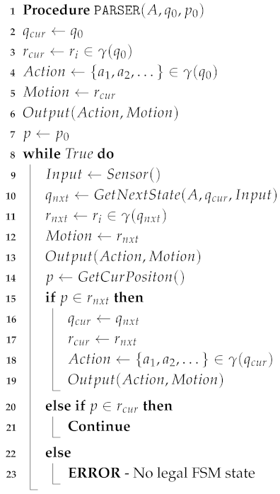
The purpose of synthesis is to construct a reactive controller for the UAV, i.e., generating execution trajectories satisfying given temporal specifications. To achieve this, we formalize a system model comprising UAVs and their environment through GR(1) game theory.
Consider a multi-UAV system with agents
. For any UAV
, other UAVs are treated as its dynamic environmental components. which means one UAV can obtain dynamic information from both the environment and other UAVs. Then, we construct the
Position,
Action, and
Sensor models for the multi-UAV system as follows (see
Table 13) [
5]:
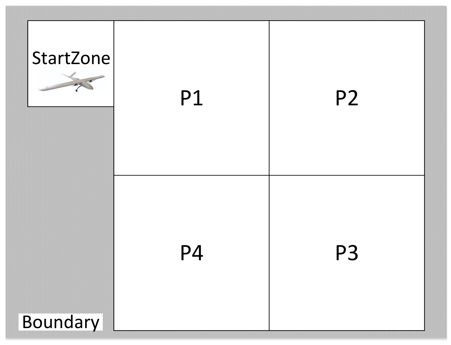
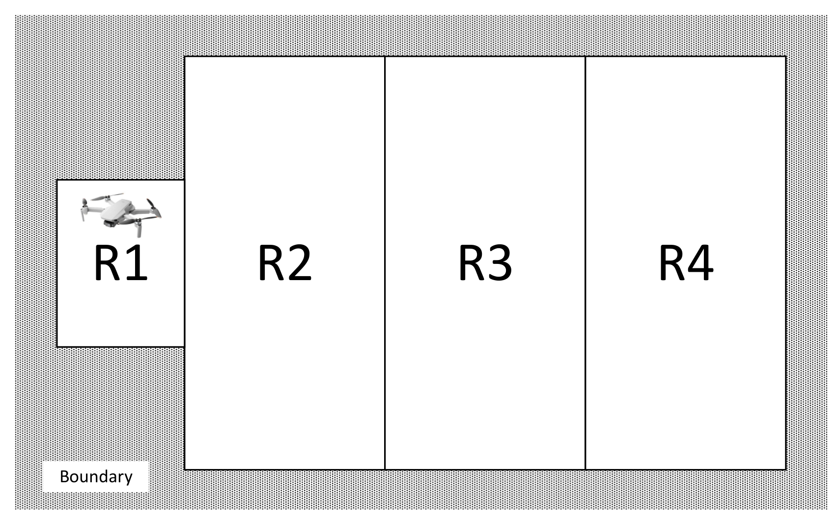
Position Model. We assume the workspace is a plane polygon, denoted by a position coordinate set Z partitioned into finite convex polygonal zones , where for and . The Boolean proposition is True if UAV is in zone . Obviously, the proposition is a mutual exclusion constraint, namely, exactly only one element in is True at any step.
Action Model. UAVs must execute action sequences to satisfy system functionalities, including “patrolling”, “target navigation”, and “alarm triggering”. These actions are denoted by , and is True if UAV executes action such as “patrolling”. Here, we define as the behaviors set of .
Sensor Model. The environment is perceived through UAV sensors (e.g., GPS, LiDAR). We abstract the sensors as a set of binary environment propositions . UAV can receive data from sensor , which holds True if it is triggered (e.g., Lidar senses surrounding obstacles).
Summarily, we define , , and as the sets of propositions , , and , respectively, as well as . Based on and , the multi-UAV system model can be given with the sets of behaviors and sensors.
7.2. Unmanned Aircraft System Description Language
Based on our framework and UAS model, in order to facilitate users in flexibly configuring the hardware and software resources, designing the UAS properties and tasks for the multi-UAV system, we borrowed the concept of domain-specific languages (DSL) and designed the UAS-DL for our method.
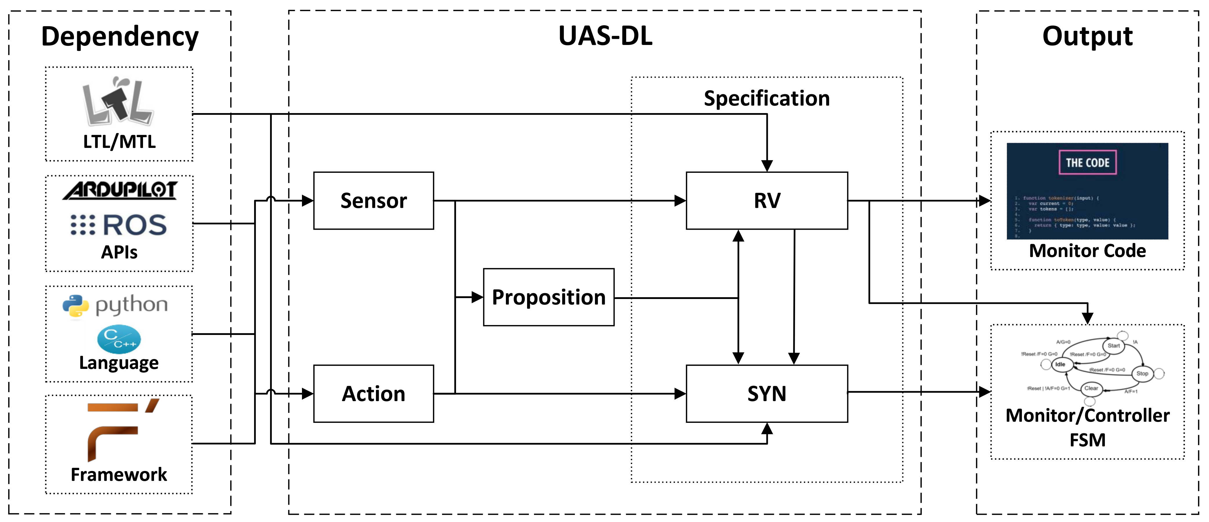
Figure 15 illustrates the architecture of UAS-DL. A core feature lies in its capability to abstractly model heterogeneous UAS hardware/software resources as atomic propositions, which are directly applicable to the formal verification of UAS properties and task specifications.
The UAS-DL framework comprises four core components:
: Sensor information extracted from APIs of simulation platforms (e.g., ArduPilot and ROS)
: Actuator commands derived through Sensor data processing
: Propositional logic composed of the propositions from in and
: Specifications describing UAV priorities and tasks in LTL/MTL containing:
- –
: Runtime verification monitor specification describing UAV priorities
- –
: GR(1) synthesis specification mainly describing UAV tasks
The specifications can be converted into monitors in the form of code or FSM, while the specifications can be synthesized into the FSM controller.
The simplified syntax of UAS-DL (
Table 14) comprises five core components, which correspond to the four parts in the UAS-DL architecture (among them,
the GeneralSetting and
the UAVSetting correspond to
the Specification):
: Sensor definition composed of key words “Inport”, “OutPort”, “Var” and “Set”
: Action definition composed of key words “InCmdport”, “InDataport”, “OutPort”, etc.
: Propositions definition composed of propositions defined by or
: Global constraints in LTL/MTL specification
: UAV constraints in LTL/MTL specification
Production rules are printed in bold, and printable contents are enclosed in “quotation marks”. We use words with the suffix ID (e.g., PpID) (proposition ID) to denote element names. Multiplicity is defined using the following:
*: Zero or more repetitions
+: At least one occurrence
?: Optional element (zero or one instance)
To demonstrate UAS-DL syntax, we use the highlighting conventions:
Sensor, VAR, Set (UAS-DL keywords in blue)
SenName, POS (user-defined identifiers in green)
Lat,
Lng (other language (e.g., F Prime Prime (FPP) [
40]) predefined keywords in orange)
"// Sensor initialization" (code comments in gray)
In the following sections, we will give several examples to demonstrate the usage of each part of the UAS-DL.
Table 14.
Syntax of UAS-DL.
Table 14.
Syntax of UAS-DL.
| UAS-DL syntax: | | |
| UAS-DL | ::= | Sensor Action* Proposition* GeneralSetting UAVSetting+ |
| Basic definitions: | | |
| Number | ::= | (’0’ .. ’9’) + (’.’ (’0’ .. ’9’)+)? |
| ID...PpID, Param, Atomic | ::= | [A-Za-z0-9]+ |
| Message | ::= | [A-Za-z0-9’∼]+ |
| Code | ::= | ∼[]+ |
| Url | ::= | [A-Za-z0-9./]+ |
| Basic syntax: | | |
| TimeInterval | ::= | ’[’ Number ’:’ Number ’]’ |
| Expression | ::= | Expression (’&’ | ’|’ | ’,’) Expression | Expr (’>’ | ’<’ | ’’ | ’’ | ’=’) Expr |
| Expr | ::= | Expr (’*’ | ’/’) Expr | Expr (’+’ | ’−’) Expr | Number | (ID | Message) | ’(’ Expr ’)’ |
| LTL | ::= | "True" | "False" | Atomic | ’(’ LTL ’)’ | LTL (’&’ | ’|’ | ’’ | ’’) LTL | (’!’ | ’∼’) LTL |
| | | | (’[]’ | ’G’ | ’’ | ’F’ | ’X’ | "Next") LTL | LTL ’U’ LTL |
| MTL | ::= | "True" | "False" | Atomic | ’(’ MTL ’)’ | MTL (’&’ | ’|’ | ’’ | ’’) MTL| (’!’ | ’∼’) MTL |
| | | | (’[]’ | ’G’ | ’’ | ’F’ ) TimeInterval? MTL | (’X’ | "Next") MTL | MTL ’U’ TimeInterval? MTL |
| GR1 | ::= | "True" | "False" | Atomic | Shared | ’(’ GR1 ’)’ | GR1 (’&’ | ’|’ | ’’ | ’’) GR1 | (’!’ | ’∼’) |
| | | GR1| (’[]’ | ’G’ | ’’ | ’F’ | ’X’ | "Next") GR1 |
| SpecParm | ::= | ’(’ Param? (’,’ Param)? | (ParamID:Param (’,’ ParamID:Param)*) ’)’ |
| SpecExp | ::= | GR1SpecParm? |
| Map | ::= | "MapInfo" ’:’ (Url | GR1) ’;’ |
| Default | ::= | "Default" ’:’ ModeID ’;’ |
| RvPriority | ::= | “RvProity” ’:’ Number ’;’ |
| SYNPriority | ::= | “SynPriority” ’:’ Number ’;’ |
| EnvParms | ::= | "Env" ’:’ Atomic (’,’ Atomic)+ ’;’ |
| SysParms | ::= | "Sys" ’:’ Atomic (’,’ Atomic)+ ’;’ |
| Init | ::= | "Init:" (((’!’ | ’∼’)? Atomic) (’,’ ((’!’ | ’∼’)? Atomic))* SpecParm? ’;’)* |
| EnvRule | ::= | "EnvRule:" (GR1 ’;’)* |
| EnvGoal | ::= | "EnvGoal:" (GR1 ’;’)* |
| SysRule | ::= | "SysRule:" (SpecExp ’;’)* |
| SysGoal | ::= | "SysGoal:" (SpecExp ’;’)* |
| Monitor | ::= | (MonitorID ’:’ (LTL | MTL) (’,’ CounterMeasureID)? (’,’ Number)? (’,’ Number)? |
| | | (’,’ ’N’|’C’|’T’)? (’,’ Number ’s’|’ms’)?’;’)* |
| RV | ::= | "RV" ’{’ Monitor ’}’ |
| SYN | ::= | "SYN" ’{’ Default? EnvParms? SYSParms? Init? EnvRule? EnvGoal? SYSRule? SysGoal? ’}’ |
| Sensor syntax: | | |
| Sensor | ::= | "Sensor" SenID ’{’ |
| | | ("InPort" ’:’ InID ’:’LogID (’,’ LogID)* ’;’)? |
| | | "OutPort" ’:’ OutID (’,’ OutID)* ’;’ |
| | | ("VAR" ’:’ VarID (’,’ VarID)* ’;’)? |
| | | "Set" ’{’ (SetID ":=" Expression ’;’ | ’EmbCode’ ’[’ CodeID ’]’ (’*’ | ’+’)? |
| | | ’:’ (LogID(’*’)? (’,’ LogID(’*’)?)*)? "" Code ";")+ ’}’ |
| | | ’}’ |
| Action syntax: | | |
| Action | ::= | "Action" ActID ’{’ |
| | | "InCmdport" ’:’ CmdID (’,’ CmdID)* ’;’ |
| | | ("InDataport" ’:’ (DataID ’:’LogID (’,’ LogID)* ’;’)*)? |
| | | ("OutPort" ’:’ OutID (’,’ OutID)* ’;’)* |
| | | ("VAR" ’:’ VarID (’,’ VarID)* ’;’)? |
| | | ("CMD" ’{’ (CmdID ’:’ " Code ";")* ’}’)* |
| | | "Set" ’{’ (SetID ":=" Expression ’;’ | "EmbCode" ’[’ CodeID ’]’ (’*’ | ’+’)? |
| | | ’:’ (CmdID | LogID)(’*’)? (’,’ (CmdID | LogID)(’*’)?)* "" Code ";")+ ’}’ |
| | | ’}’ |
| Proposition syntax: | | |
| Proposition | ::= | "Proposition" PropsID ’{’ (PropID ’:’ PpID ((’,’ | ’&’ | ’|’) PpID)* ’;’)+ ’}’ |
| GeneralSetting syntax: | | |
| GeneralSetting | ::= | "General" ’{’Map Default RvPriority? SYNPriority? RV? SYN? ’}’ |
| UAVSetting syntax: | | |
| UAVSetting | ::= | "UAV" UAVID ’{’ Default? RV? SYN? ’}’ |
7.2.1. Sensor
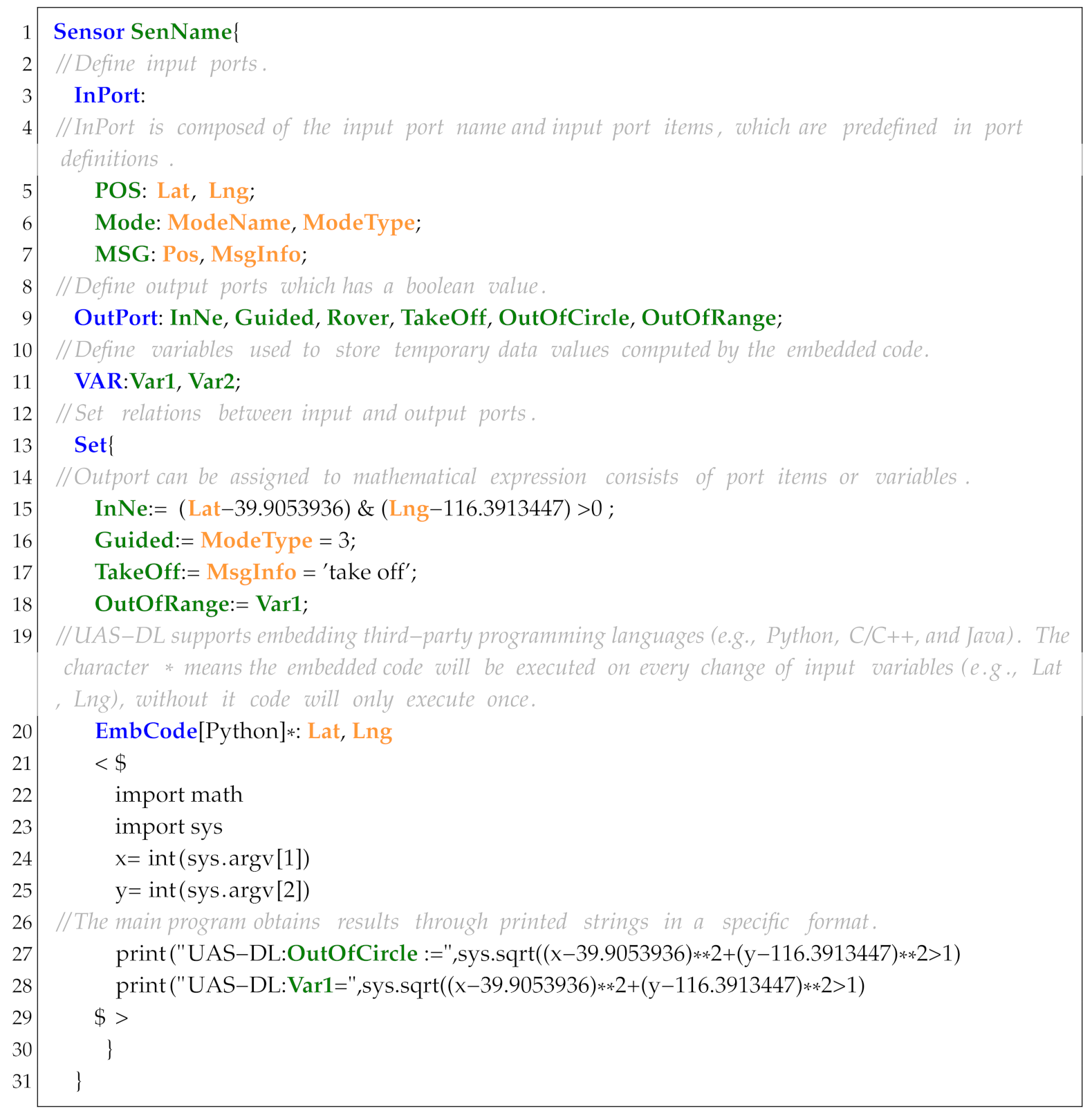
Sensor is designed to process and convert the extracted UAS running trajectories (e.g., UAS logs) into Boolean expressions that can be directly used in propositions and specifications. In order to be compatible with the F’ development framework, the syntax of Sensor is designed to support fast conversion into F’ components. As shown in Listing 6, a sensor starts with the keyword Sensor followed by a sensor name. Additional keywords include InPort, OutPort, VAR, Set, and EmbCode.
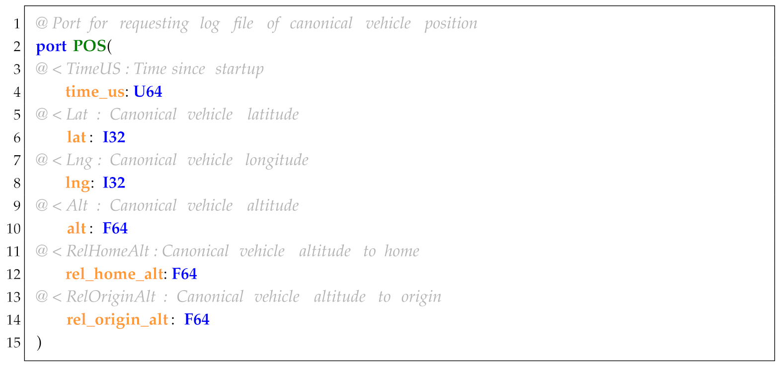
InPort is used to define the input hardware and software resources, which are mainly obtained from the sensors, ROS topics, and UAS logs. For convenience, we first define the commonly used software and hardware resources of UAS-DL in FPP. As shown in Listing 7, it represents position information defined in FPP based on data extracted from ArduPilot logs. Using this predefined port information, we can conveniently define the input variables. As an example, to define the latitude and longitude variables (Listing 6, line 5), we analyze the UAS logs to identify related entries (e.g., GPS sensor recordings), define the log items (Lat, Lng) in FPP, and finally, reference these predefined log data.
| Listing 6. Demo code of the keyword Sensor. |
![Drones 09 00353 i006]() |
| Listing 7. Demo code of port in FPP. |
![Drones 09 00353 i007]() |
OutPort is used to define the output variables that can serve as input variables for other components. For example, the output port variables (Listing 6, line 9) denote the following: InNe: whether the UAV is in the northeast of the origin; Guided: whether the flight mode is set to Guided; Rover: whether the flight mode is set to Rover; TakeOff: whether the UAV has taken off; OutOfCircle/OutOfRange: whether the UAV is within or outside a circular range.
VAR is used to define the intermediate constants computed by the embedded code. For example, variable Var1 (Listing 6, line 11) stores the value generated in the embedded code (Listing 6, line 28).
Set establishes relationships between the input and output variables. For simple cases, the output variable name is entered followed by a colon and an expression combining the inputs and operators. As an example, verifying whether the UAV is northeast of the origin (longitude: 116.3913447, latitude: 39.9053936) uses the expression:
(Listing 6, line 15), where the expression’s value should have a Boolean result.
EmbLang can embed other programming languages (e.g., Python, Java, and C/C++) in UAS-DL to describe complex relationships more efficiently. As shown in Listing 6 (line 20), users must first specify the following: language type (e.g., Python), code execution mode (default: execute once, * for zero/more repetitions, + for at least one repetition), input variables (marked with * to trigger execution only when these variables change). The embedded code is written between the delimiters <$ and >$ (Listing 6, lines 21–29). The Python code in this example takes Lat and Lng as inputs to determine whether the UAV is outside a circular area centered at (39.9053936, 116.3913447) with a 1-unit radius. The results are printed in the format ““ for the parser to extract. The output variables (e.g., OutOfCircle) and intermediate variables (e.g., Var1) follow this convention.
7.2.2. Action
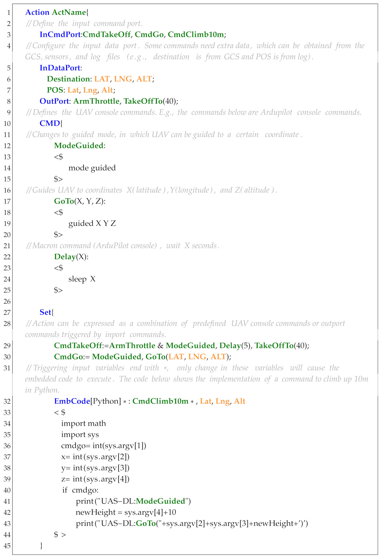
Action is designed to define the basic action, motion or countermeasure, including a sequence of UAS console commands or ROS API programs. As shown in Listing 8, an action starts with a keyword Action followed by a name. Additional keywords include InCmdPort, InDataPort, OutPort, CMD, VAR, Set, and EmbCode.
InCmdPort defines the Boolean input command that triggers the control signals. For example, the input commands in Listing 8 line 3 include CmdTakeOff (takeoff command), CmdGo (navigation command), CmdClimb10m (altitude adjustment command).
InDataPort defines the input data variables required for action execution. These variables are typically sourced from the sensors, actions, ROS topics, UAS logs, or GCS. For instance, the GoTo action relies on GCS-provided coordinates: (Lat, Lng, Alt).
OutPort defines the output variables for inter-component communication. Complex actions may depend on others; thus, the output variables enable data exchange between actions. For example, in Listing 8 (line 8), the variables are: ArmThrottle (throttle arming), TakeOffTo(40) (takeoff altitude: 40 meters). Among them, command TakeOffTo and parameter 40 are connected to the InCmdPort and InDataPort port of the sub-action component separately.
VAR declares parameters identical to those in the Sensor component.
CMD defines the UAV console commands. By sequencing predefined commands between <$ and >$, users generate executable command streams. For example, in Listing 8 (ll, 12–25): ModeGuided (switches flight mode to guided), GoTo (navigates to target coordinates), and Delay (inserts timed pauses).
Set configures action triggers via input variable changes. Logical operators (&(and), |(or), ,(sequence)) combine commands. For example, CmdTakeOff (Listing 8, line 29) executes: (1) ArmThrottle (arm throttle), (2) ModeGuided (activate guided mode), (3) Delay(5) (5-second delay), (4) TakeOffTo (40) (ascend to 40 m).
EmbCode embeds other languages identically in Sensor.
| Listing 8. Demo code of the keyword Action. |
![Drones 09 00353 i008]() |
7.2.3. Proposition
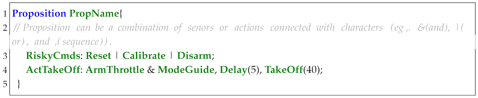
Proposition defines complex propositions by combining sensors and actions (Listing 9). For example, RiskyCMD configures dangerous UAV instructions through a combination of three sensors, Calibrate, and Disarm; Act_TakeOff implements the similar TakeOff action sequence defined in Listing 8 (line 29) through a combination of four actions.
| Listing 9. Demo code of the keyword Proposition. |
![Drones 09 00353 i009]() |
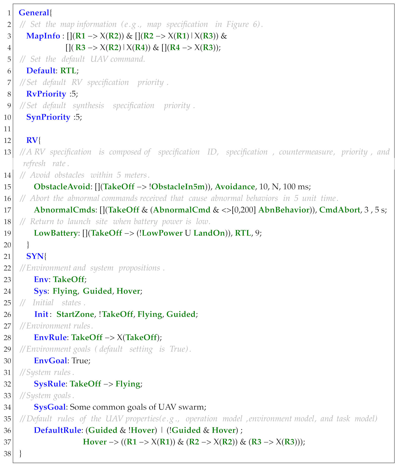
7.2.4. General
General defines the core configurations for multi-UAV systems (e.g., drone swarms), including the global properties and task parameters. As shown in Listing 10, it begins with the keyword General and supports 13 other keywords: MapInfo, RvPriority, SynPriority, RV, SYN, Default, Env, Sys, Init, EnvGoal, SysRule, SysGoal, and DefaultRule.
| Listing 10. Demo code of the keyword General. |
![Drones 09 00353 i010]() |
MapInfo defines the geospatial constraints through LTL specifications that describe the connectivity of each region on the map or external configuration files (e.g., "map_config.ltl").
Default sets the default action taken under extreme situations (e.g., communication loss or mission abort conditions).
RvPriority sets the default priority for countermeasures.
SynPriority sets the default priority for actions/motions.
RV defines the safety and task properties for UAVs. Each property contains six components:
Property variable: used as a sensor proposition in task specifications
Specification: an LTL/MTL formula describing the monitored behavior
Countermeasure: the action triggered on property violation
Type: countermeasure types (C (Critical), N (Non-critical), and T (Termination))
Priority: an integer (1–10) determining scheduling precedence (higher values indicate urgency)
RefreshRate: monitor state reset intervals (default: ∞, i.e., never refreshed)
For example, in Listing 10, line 15, the specification ObstacleAvoid mandates a minimum obstacle distance of 5 meters after take off. Violations trigger the non-critical Avoidance action (priority 10), resetting the monitor state within 100 ms.
SYN defines global task specifications for a multi-UAV System based on GR(1) specification. Given a task description , its semantics are structured as follows:
Env: , i.e., the set of environment input propositions.
Sys: , i.e., the set of system output propositions.
Init: , i.e., the initial states of both the environment and UAS.
EnvRule: , transition constraints of the environment.
EnvGoal: , i.e., the environmental behavioral objectives.
SysRule: , i.e., transition constraints of UAS.
SysGoal: , i.e., mission goals for UAVs.
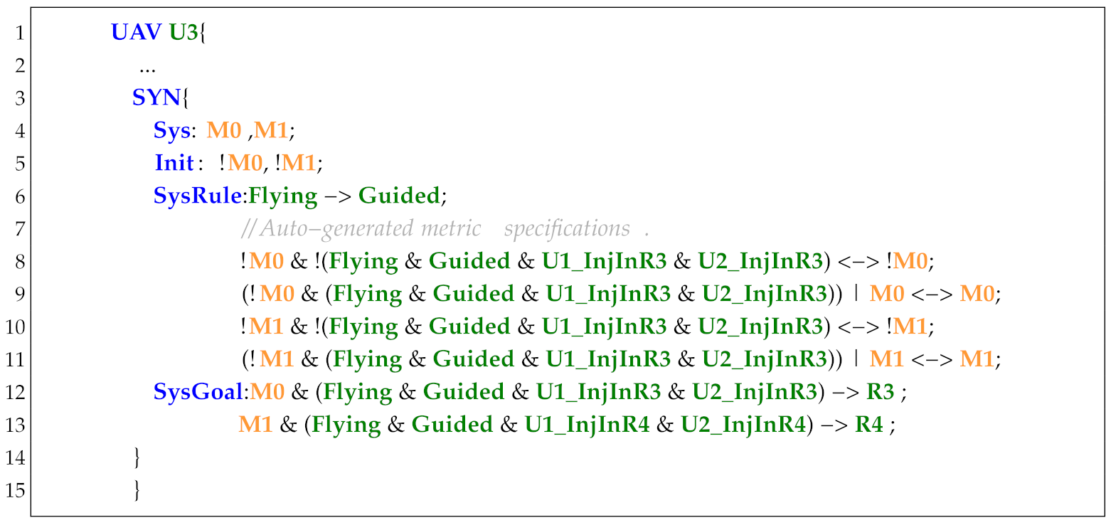
DefaultRule enforces the default UAV compliance properties. If all propositions of a rule exist in a UAV’s specifications, the rule is directly added; partial matches trigger Disjunctive Normal Form (DNF) conversion of the shared propositions.
Operators
in
EnvRule/
SysRule and □ in
EnvGoal/
SysGoal may be omitted for brevity, as the parser completes them automatically. Operator precedence (strongest to weakest):
All binary operators associate left-to-right (e.g.,
).
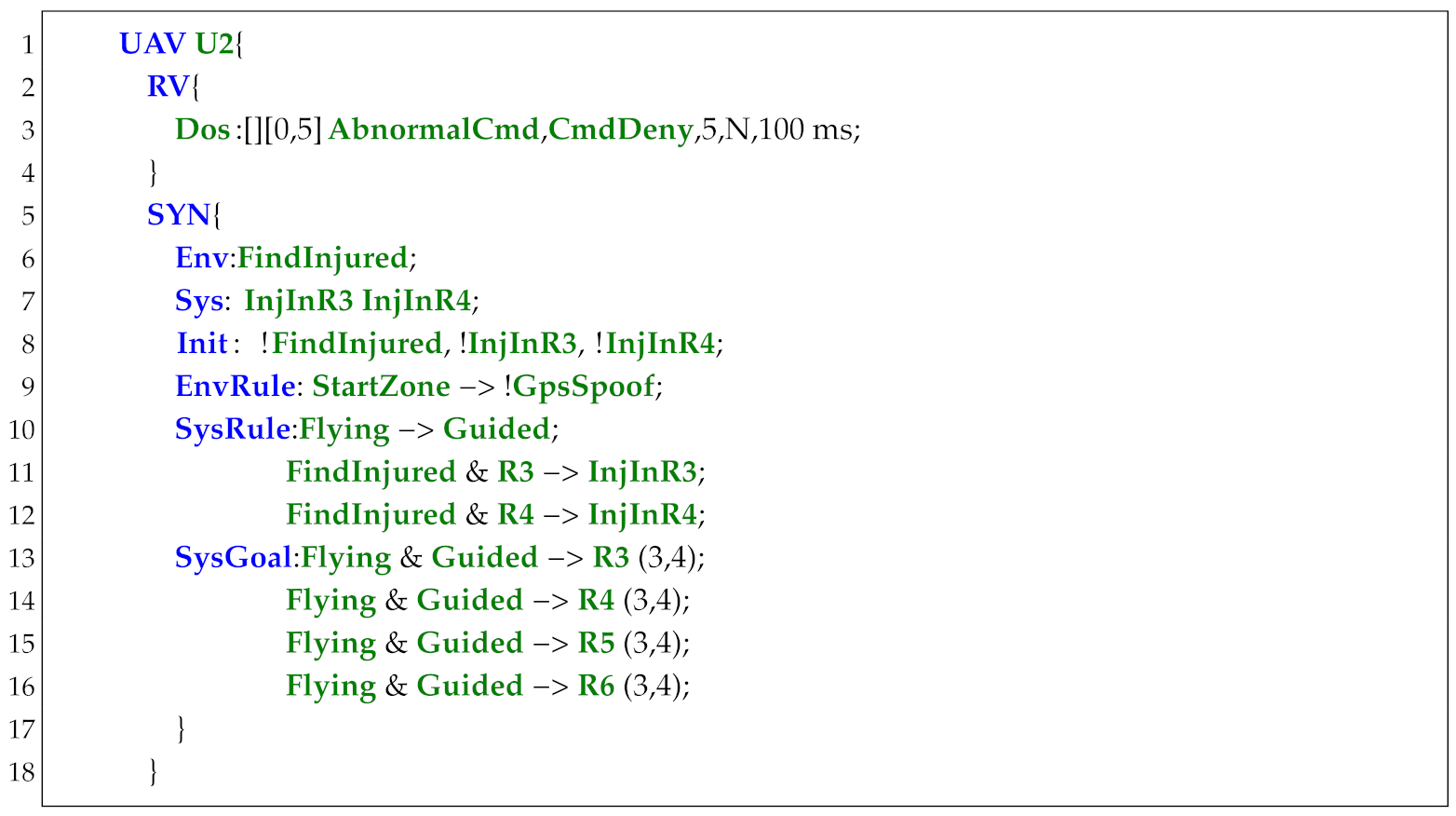
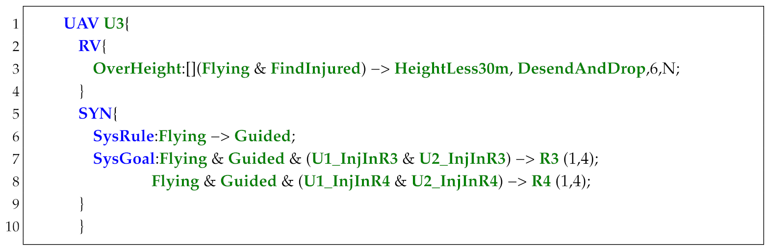
7.2.5. UAV
UAV defines UAV-specific properties and tasks, inheriting global configurations from General. As shown in Listing 11, it begins with the keyword UAV followed by the UAV name, and supports 10 other keywords: Default, RV, SYN, Env, Sys, Init, EnvRule, EnvGoal, SysRule, and SysGoal, which have the same usage as the keywords in General:
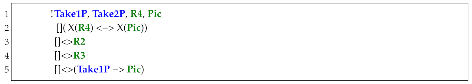
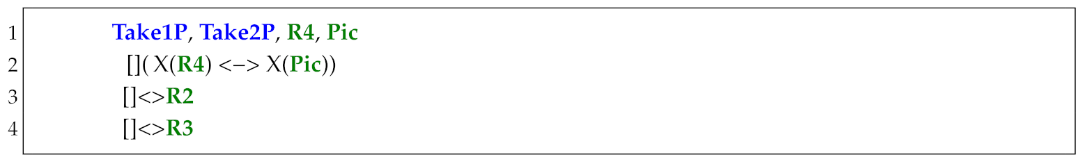
As shown in Listing 12, to express the fulfilment times or action priority of a specification, we can add the parameter “” or “” to the end of the specification, where “3“ denotes the fulfilment times and “6“/“1“ are action priorities. To support multi-UAV cooperation, a UAV may reference other UAVs’ propositions in its task specification, e.g., UAV1_InjuredInR1 (Listing 12, line 7) represents the proposition InjuredInR1 of UAV1 defined in Listing 11.
| Listing 11. Demo code of the keyword UAV. |
![Drones 09 00353 i011]() |
| Listing 12. A example of parameters setting and shared propositions of UAV. |
![Drones 09 00353 i012]() |


