Article

Pigeon-Inspired UAV Swarm Control and Planning Within a Virtual Tube

1
The School of Mathematical Sciences, Beihang University, Beijing 100191, China
2
The School of Automation Science and Electrical Engineering, Beihang University, Beijing 100191, China
*
Author to whom correspondence should be addressed.
Drones 2025, 9(5), 333; https://doi.org/10.3390/drones9050333
Submission received: 28 February 2025 / Revised: 6 April 2025 / Accepted: 12 April 2025 / Published: 25 April 2025
(This article belongs to the Special Issue Biological UAV Swarm Control)

Abstract

:
To guide the movement of a UAV swarm in an obstacle-dense environment, a curved regular virtual tube based on pigeon-inspired optimization (PIO) is planned in this paper. There is no obstacle within the virtual tube, which serves as a safe corridor for UAVs. Then, a distributed swarm controller based on a pigeon flocking hierarchical model is proposed, enabling all UAVs to pass through a virtual tube, guaranteeing safety between UAVs and keeping within the virtual tube. Numerical simulations demonstrate the effectiveness of the proposed virtual tube planning and UAV swarm passing-through methods.

1. Introduction

Recently, UAV swarm navigation through complex environments has attracted increasing attention. The goal is to guide each UAV from the starting point to the endpoint, avoid conflicts with other UAVs, and stay away from environmental obstacles [1].
Classical methods for planning and controlling UAV swarms in obstacle-dense environments have been proposed, including formation control [2], trajectory planning [3], and control-based methods [4]. Formation control methods enable the swarm to maintain a specific formation while navigating cluttered environments. However, when the swarm encounters extreme conditions, such as narrow spaces or a significantly increased number of UAVs, the adaptability and scalability of the swarm formation are reduced. The trajectory planning method generates collision-free paths for each UAV, ensuring that the trajectories of all UAVs do not overlap or intersect with obstacles. However, as the number of UAVs in the swarm increases, the computational complexity of the trajectory planning method increases significantly.
Furthermore, communication uncertainties among UAVs may render the trajectory planning process infeasible. The control-based methods include the potential field method [5], vector field control method [4] and control barrier function (CBF) method [6], flocking control method [7], etc. Control-based methods offer significant implementation and computational efficiency advantages, as they can directly generate control commands for UAVs. However, they sometimes exhibit reduced control performance, and deadlocks may occur.
In our previous work, a virtual tube framework [5,8] is proposed for guiding UAV swarms through complex environments. The virtual tube is free of obstacles, providing a safe space for UAVs in an obstacle-dense environment. It is generated based on a continuous curve, and its radius can be adjusted. As a result, the virtual tube is well suited for directing UAV swarms through cluttered environments. The distributed control method directs the UAVs along the generating curve, enabling them to avoid conflicts with other UAVs and remain within the virtual tube. Consequently, the swarm reaches the target area while ensuring safety. The basic virtual tube framework involves two primary problems: virtual tube planning and virtual tube passing-through control [8]. The basic curved virtual tube control method is studied in [8], and the proposed method is a modified version of the artificial potential field (APF) approach. Each control objective in the APF approach can be represented by a potential function, which may be attractive or repulsive. However, when guiding many UAVs through confined areas in complex environments, the basic virtual tube control method may face inherent limitations, such as congestion.
Regarding virtual tube planning, a standard method is proposed in [9]. The generating curve of the virtual tube is determined using a path-finding method, and its radius is established by formulating optimization problems. However, this regular tube generation method is not applicable in specific extreme environments. For example, in narrow spaces or environments dense with obstacles, the width of the generated virtual tube may become excessively narrow. The optimal virtual tube is introduced in [10], where an infinite number of optimal trajectories are produced by solving a finite set of optimization problems. However, optimal virtual tube planning does not account for UAV swarm control within the virtual tube.
Considering the similarity between pigeon flocks and UAV swarms, pigeon flocking control is first proposed in [11]. The distributed pigeon flocking control method enables UAV swarms to navigate through obstacle-dense environments while avoiding conflicts with one another. The core of virtual tube planning is the planning of the generating curve based on the path planning algorithm. Classical methods are widely used in multi-UAV path planning, such as the A* algorithm [12], the Dijkstra algorithm [13], the RRT algorithm [14], etc. These approaches effectively reduce computational complexity and enhance practical performance. However, their reliance on comprehensive global environmental data limits their efficiency [15]. In recent years, bio-inspired intelligent optimization methods have been extensively applied to UAV swarm path planning. Unlike classical approaches, bio-inspired optimization algorithms do not depend on the mathematical properties of the problem, impose no strict requirements on initial values, and can effectively handle high-dimensional, complex optimization problems. Typical bio-inspired optimization algorithms include particle swarm optimization [16], ant colony optimization [17], and genetic algorithms [18]. Recently, inspired by the collective behavior of pigeons, a bio-inspired optimization algorithm known as pigeon-inspired optimization (PIO) was introduced in [19]. Compared with other bio-inspired optimization algorithms, PIO has fewer control parameters and is easier to implement. For example, a social-class pigeon-inspired optimization (SCPIO) method was developed for UAV swarm path planning in [20], and a dynamic discrete pigeon-inspired optimization (DDPIO) approach was proposed to address UAV swarm search and attack mission planning [21]. The advantages of PIO include its self-organization property for searching global optima and its adaptability to complex systems. In UAV swarm path planning, the number of waypoints and candidate paths can be regarded as the dimension and solution of PIO, respectively. PIO can then be used to solve the path planning problem by optimizing the arrangement of waypoints along the candidate path. Compared to existing path planning algorithms, PIO can further leverage ordinary time bases to simplify the computation of UAV coordination costs. Therefore, PIO is a powerful tool for path planning research.
To address the limitations of existing methods and further enhance the safety and efficiency of UAV swarm navigation in complex environments, new virtual tube planning and control methods inspired by pigeon behaviors are proposed in this paper. The presented method integrates the advantages of the pigeon-inspired flocking and virtual tube methods, offering a safer and more efficient framework for UAV swarm control and planning. The main contributions of this work are summarized as follows:
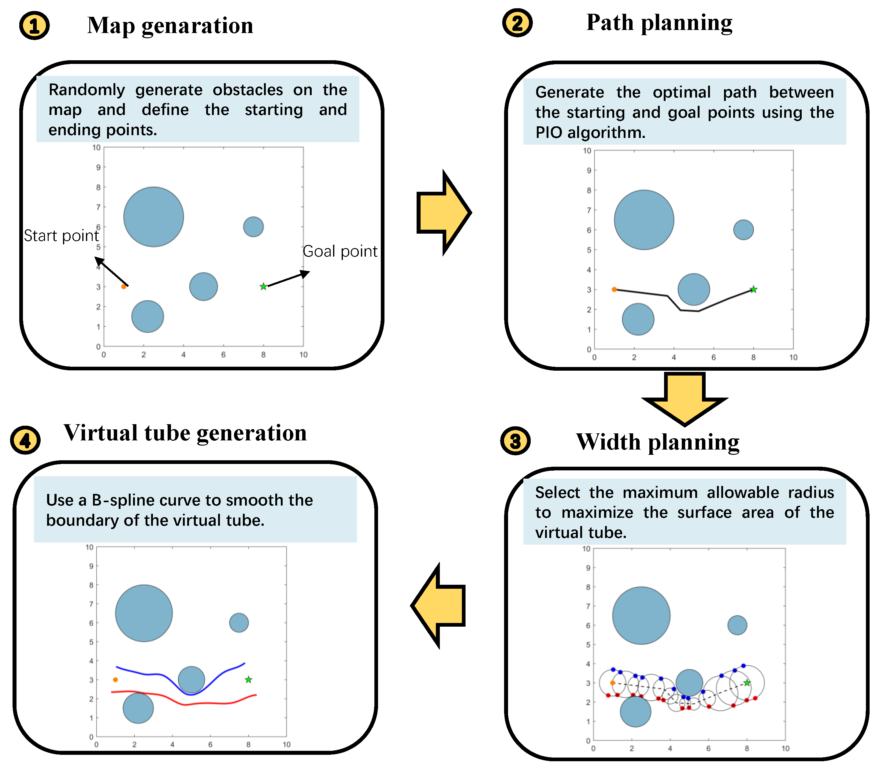
  • Curved virtual tube planning based on pigeon-inspired optimization (PIO): A novel virtual tube planning method is proposed using PIO, ensuring obstacle-free paths for UAV swarms. This approach adapts better to narrow or obstacle-dense environments than traditional methods, avoiding excessively narrow tubes.
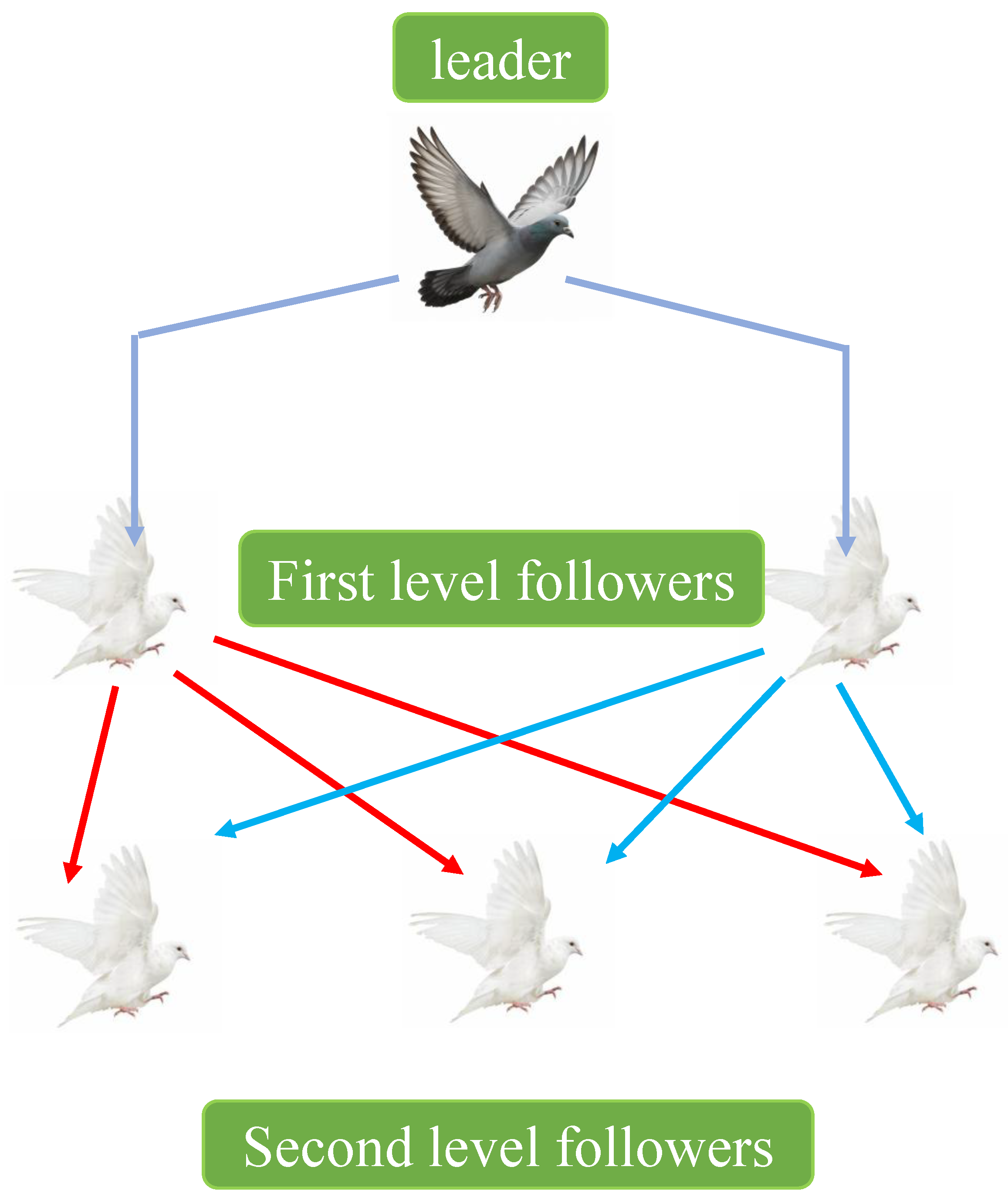
  • Distributed swarm controller inspired by pigeon flocking: A distributed controller based on pigeon flocking hierarchical behavior is designed to guide UAVs within the virtual tube. It guarantees collision avoidance, safe passage, and adherence to the tube, addressing scalability and deadlock issues in complex scenarios.
  • Integrated framework combining pigeon flocking behaviors and virtual tube methods: This work integrates pigeons’ flocking properties with virtual tube techniques, offering a unified framework for both planning and control. It enhances navigation efficiency and safety for large-scale UAV swarms in cluttered environments.
This paper is organized as follows: Section 2 introduces the preliminaries on modeling and problem formulation; Section 3 presents the virtual tube planning method based on pigeon-inspired optimization; Section 4 describes the controller design; and Section 5 presents and analyzes the simulation results.

2. Preliminaries and Problem Formulation

This section begins by introducing the concepts of UAV modeling and the virtual tube, followed by the problem formulation, which includes virtual tube planning and controller design.

2.1. UAV Modeling

The UAV swarm consists of N homogeneous UAVs. In the 2D Cartesian coordinate system, the motion of the ith UAV is described as
p ˙ i = v i v ˙ i = l i v i v c , i
where l i > 0 , p i R 2 and v i R 2 are the position and velocity of the ith UAV, and v c , i is the velocity command of the ith UAV, i = 1 , 2 , , N . The control gain l i depends on the maneuverability of the ith UAV, which can be obtained through experiments. In this paper, the motion of each UAV is transformed into a single integrator form. The filtered position is defined as
ξ i = p i + 1 l i v i .
Based on (1), there exists
ξ ˙ i = p ˙ i + 1 l i v ˙ i = v c , i .
Then, the relative position error between the ith UAV and the jth UAV is
ξ ˜ i j = ξ i ξ j
where i , j = 1 , 2 , , N , i j .
Similar to our previous work [5,22], define the physical area of the UAV as a circle with radius r p , and the safety area with safety radius r s . Specifically, r p < r s exists.

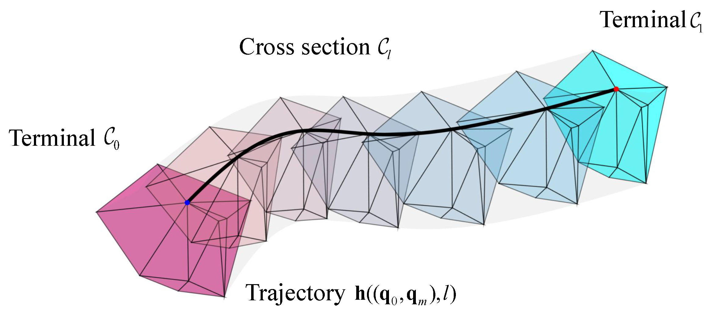
2.2. Virtual Tube Model

As shown in Figure 1 [10], a virtual tube T is defined in an n-dimensional space represented by a 4-tuple ( C 0 , C 1 , f , h ) where C 0 , C 1 are terminals, and are disjoint bounded convex subsets; denote f as a diffeomorphism: C 0 C 1 , and there is a set of order pairs P = { ( q 0 , q m ) , q 0 C 0 , q m = f ( q 0 ) C 1 } ; h denotes a smooth map: P × [ 0 , L ] T . Therefore, the virtual tube T is defined as
T = { h ( q 0 , q m , l ) | ( q 0 , q m ) P , l [ 0 , L ] } ,
and h ( ( q 0 , q m ) , 0 ) = q 0 , h ( ( q 0 , q m ) , L ) = q m . The function h ( q 0 , q m , l ) is called a trajectory for an order pair ( q 0 , q m ) . The cross-section at arc length l is defined as
C l = { h ( q 0 , q m ) , l | ( q 0 , q m ) P } .
The surface of T is the boundary, represented as T .

2.3. Problem Formulation

This paper addresses two main problems: virtual tube planning and velocity command design for swarm UAVs within the virtual tube. An additional assumption is presented as follows:
Assumption 1.
The velocity command for approaching the destination v l , i satisfies v l , i = 0 when the ith UAV reaches the finishing line.
  • Virtual tube planning: Denote X free = X / X obs as free space, where X R 2 is the configuration space and X obs is the obstacle space. The virtual tube planning method aims to find the center path (generating curve) in free space, and the radius of the virtual tube is determined, satisfying the requirement of smoothness and width.
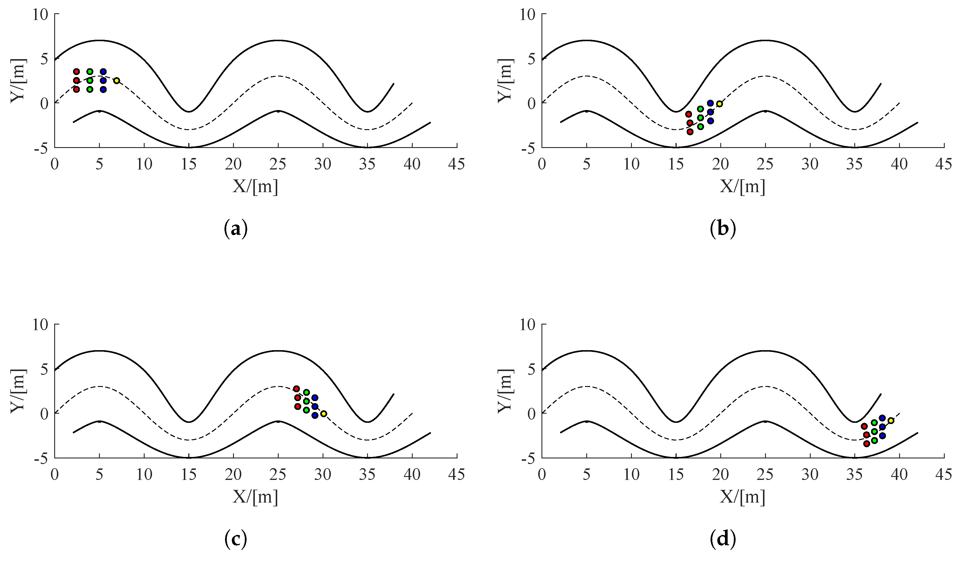
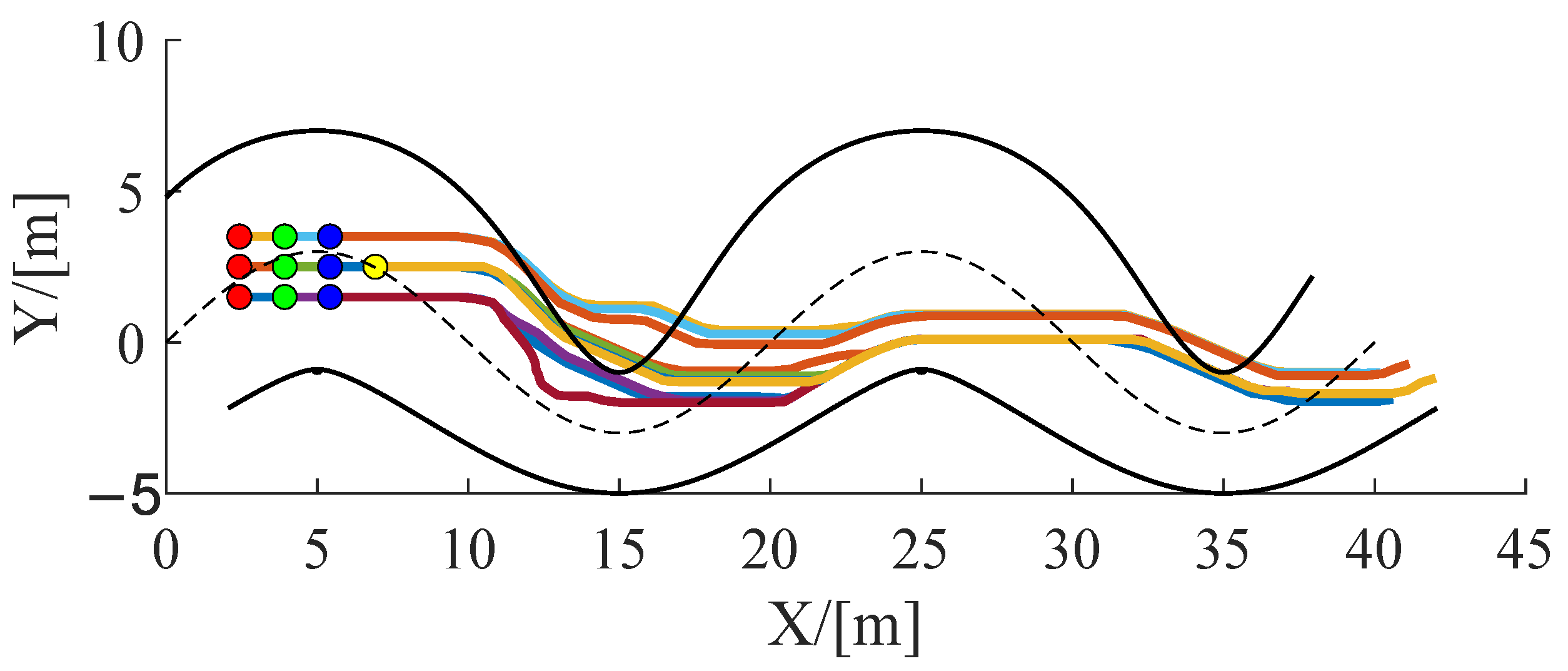
  • Velocity command design: Based on the assumption above, design the velocity command v c , i based on the pigeons flocking behaviors. During the passing-through process, all UAVs should avoid collisions with each other and stay within the curved virtual tube.

3. Virtual Tube Planning Based on Pigeon-Inspired Optimization

Virtual tube planning aims to enable UAV swarms to navigate dense obstacle environments more safely and efficiently. The virtual tube planning process consists of two main steps: generating the curve and planning the radius of the virtual tube [9]. Initially, a pathfinding process based on the pigeon-inspired optimization (PIO) algorithm generates discrete path points from the starting point to the endpoint. A brief introduction to the PIO algorithm follows.
PIO is an evolutionary algorithm that mimics the homing behavior of pigeons. During this process, pigeons first rely on the sun and geomagnetic fields for navigation. As they approach their destination, they switch to using landmarks. The map, compass, and landmark operators represent these two navigation strategies where the map and compass operators model sun/geomagnetic navigation, while the landmark operator mimics landmark-based homing. The PIO algorithm applies these operators sequentially, with the pigeon’s position representing a feasible solution. The aim is to identify the optimal solution among all the pigeons.
The new position and velocity of pigeon i at tth iteration for the map and compass operator are calculated as follows:
V i ( t ) = V i ( t 1 ) · e R t + r a n d × ( X gbest X i ( t 1 ) ) X i ( t ) = X i ( t 1 ) + V i ( t )
R is the map and compass factor, and r a n d is a random value ranging from 0 to 1; X gbest represents the global best position, corresponding to the highest fitness value. As shown in Figure 2, the position of the ith pigeon at tth iteration for the landmark operator is updated as follows [19]:
N p ( t ) = ceil N p ( t 1 ) 2
X c ( t ) = i = 1 N p ( t ) X i ( t ) × fitness ( X i ( t ) ) N p i = 1 N p ( t ) fitness ( X i ( t ) )
X i ( t ) = X i ( t 1 ) + r a n d × ( X c ( t 1 ) X i ( t 1 ) )
where N p denotes the number of pigeons, and X c represents the center position of the pigeons. The fitness(·) function is used to evaluate the quality of each pigeon and is defined as follows: fitness ( X i ( t ) ) = 1 f ( X i ( t ) ) + ε for minimum optimization problems, and fitness ( X i ( t ) ) = f ( X i ( t ) ) for maximum optimization problems.
This paper’s objective function f ( · ) represents the total path length. Denote the number of waypoints as D w . The cost function is then given by f = i = 1 D w L i , where L i denotes the length of each path segment.
Based on the generating curve obtained above, the boundary of the tube is determined by the radius of the virtual tube. The objective is to make the surface of the virtual tube as large as possible. To maximize the surface of the virtual tube’s area, the radius of the tube should be maximized. The radius of the virtual tube corresponding to waypoint D P i is the minimum distance from obstacles λ min , i . Finally, the B-spline curve is used to smooth the boundary of the virtual tube. The overall virtual tube planning process is shown in Figure 3.

4. Pigeon-Inspired Velocity Command Design for UAV Swarm

4.1. Pigeon Flocking Hierarchical Strategies

This subsection briefly introduces typical hierarchical strategies in pigeon flocks, including leader–follower interactions and hierarchical leadership networks [11]. As illustrated in Figure 4, the hierarchical leadership network consists of directed and transitive leader–follower relationships [23]. This network spans multiple levels, with pigeons at higher levels exerting more significant influence on the actions of the entire flock. Furthermore, leaders at higher levels have more followers. First-level leaders carry the most weight in decision-making because they are followed by the most significant number of pigeons who continuously emulate their behavior. The hierarchical leadership network demands relatively low attention from individual members, enhancing the efficiency of information transfer and coordination while increasing resistance to interference. Each UAV interacts with its cluster partners according to the hierarchical characteristics defined for the flock, reflecting the distributed interaction rules. This hierarchical network mechanism is essential for establishing and maintaining stable UAV swarms.

4.2. Controller Design

This section introduces the distributed velocity command v c , i , inspired by hierarchical strategies observed in pigeon flocking, to address the UAV flocking problem. The velocity command consists of four components: migration control, obstacle avoidance, conflict avoidance, and hierarchical leader–follower control. The hierarchical leadership network is organized on multiple levels, with higher-level pigeons guiding the flock’s movement. Additionally, higher-level leaders exert more influence, commanding larger groups of followers. Consequently, the highest-level leaders have the most significant impact on the flock’s decision-making, as they are followed by the most significant number of pigeons, who continuously imitate their actions.
The velocity command v c , i consists of four components: migration control v l , i , which guides the swarm forward along the generating curve of the virtual tube; obstacle avoidance v t , i , which prevents collisions with obstacles; conflict avoidance v m , i , which avoids conflicts with other UAVs; and hierarchical leader–follower control v f , i , which maintains a specific relative position concerning the leader and adjusts the motion based on the leader’s position and velocity.
The migration control v f , i for guiding the UAV moving forward along the generating curve is designed as
v l , i = v m , i t c ( ξ i )
where t c ( ξ i ) represents the tangent vector of the projection of ξ i on the generating curve, and v m , i is the maximum speed of the ith UAV, i = 1 , 2 , , N .
The collective behavior of a flock of pigeons arises from simple local interaction rules, where each pigeon performs behaviors such as gathering, aligning in a queue, and maintaining distance based on the state of its companions [11]. UAVs may collide with the virtual tube’s boundaries during movement within the virtual tube. To address this issue, the flocking behavior for collision avoidance is incorporated into the velocity command. The repulsion potential function for the ith UAV to avoid collisions is expressed as follows:
V t , i = 1 d ( ξ i ) 2 r d ln d ( ξ i ) + 1 r d 2 d ( ξ i ) ,
where r d is the limited distance of the potential field influenced by the obstacle, d ( ξ i ) = ξ i ξ t , i is the position error between the ith UAV and the boundary of the virtual tube, and ξ t , i is defined as
ξ t , i = arg min ξ t ξ i ξ t , ξ t T .
The velocity command v t , i is calculated as
v t , i = k 2 j N t , i V t , i ξ i = k 2 j N t , i 1 d ( ξ i ) 1 r d 2 d ( ξ i ) ξ i
indicating that the ith UAV begins to avoid collisions when the relative position is within the limit distance r d . Consequently, there is no need to avoid obstacles at long distances in advance.
Similar to (14), the repulsion potential function for avoiding collisions between UAVs is designed as
V m , i j = 1 ξ i j 2 r c ln ( ξ i j ) + 1 r c 2 ξ i j ,
where r c is the limit distance of the repulsion potential field influence of the jth UAV, ξ i j = ξ i ξ j is the relative position between the ith UAV and the jth UAV. The velocity command is calculated as
v m , i = k 3 j N m , i V m , i j ξ i ,
where k 3 > 0 is a repulsion parameter, and N m , i is a set of UAVs satisfying the condition
N m , i = { j :   ξ i j   r c } .
Therefore, v m , i is represented as
v m , i = k 3 j N m , i 1 ξ i j 1 r c 2 ξ i j ξ i ,
indicating that the ith UAV only needs to avoid collisions with UAVs whose relative positions are within the limit distance, thus eliminating the need to account for UAVs farther away.
In the hierarchical leadership network of pigeon flocks, the leadership of higher-level pigeons over lower-level ones allows the lower-level pigeons to avoid collisions with the higher-level pigeons (i.e., collision avoidance) while also attempting to stay close to them (i.e., aggregation) and match their speed (i.e., speed alignment). For example, in Figure 5, the third-level followers fly behind the lead pigeon, the first- and second-level followers, collectively forming the leader set for the third-level followers. Specifically, the leader of the second pigeon is the first pigeon; the leaders of the fifth pigeon are the first and third pigeons; and the leaders of the sixth pigeon are the first, second, third, and fourth pigeons.
The leader–follower control component v f , i is designed as
v f , i = l e N l , i k 4 ( ξ i ξ l e ) + k 5 ( v i v l e ) ,
where N l , i represents the set of leaders for the ith UAV, v i is the individual velocity, and ξ l e and v l e represent the position and velocity of the leader, respectively. Specifically, the control commands of the lead pigeon are given independently and are not led by other pigeons.
With the descriptions above, the velocity command for the ith UAV is proposed as
v c , i = v l , i + v t , i + v m , i + v f , i .

5. Simulation Results

In this section, the effectiveness of the proposed UAV swarm control method based on pigeon flock hierarchical strategies for passing through a virtual tube and the virtual tube planning method are demonstrated through numerical simulations. All simulations in MATLAB R2022b code are executed on a PC with Intel Core i5-11300H @ 3.10GHZ CPU and 16G RAM.

5.1. UAV Swarm Control

Assume that a swarm of N = 10 UAVs navigate through a pre-designed virtual tube sufficiently wide to allow at least one UAV to pass. All UAVs follow the model in Equation (1), with the velocity command specified by Equation (20). The parameters are set as follows: the generating curve is designed as a sinusoidal curve, and the radius of the virtual tube is a continuous function. The control parameters are k 1 = k 2 = k 3 = 1 , k 4 = k 5 = 0.5 , r p = 0.25 m , r c = 0.4 m , r d = 0.4 m . The maximum speed of each UAV is v m , i = 3 m / s . The leader pigeon is represented by a yellow circle, the first-level follower pigeons with blue circles, the second-level follower pigeons with green circles, and the third-level follower pigeons with red circles. The hierarchical parameter settings of the UAV swarm are shown in Table 1. The passing-through time is used to assess control efficiency. At the same time, the minimum distance between any pair of UAVs and between UAVs and the virtual tube’s boundaries serves as the safety indicator.
Three snapshots of the simulation are shown in Figure 6, with the passing-through process lasting 11 s. As illustrated in Figure 7, the distance between any pair of UAVs remains more significant than r p = 0.25 m , indicating that no conflicts occur among the UAVs. Additionally, in Figure 8, the distance between the boundary of the virtual tube and any UAV exceeds 0.4 m , ensuring that all UAVs can safely pass through the virtual tube without collisions with one another or the tube. The flight trajectories are shown in Figure 9, these simulation results validate the effectiveness of the proposed control method in Equation (20).
To evaluate the advantages of pigeon flock hierarchical strategies in a tube control environment, the optimized flocking method is used for comparative analysis [7]. As shown in Figure 10, the passing-through time based on the flocking method is 12 s, which is longer than that of the pigeon hierarchical flocking control method. Although, as shown in Figure 11, UAVs do not collide with each other, in Figure 10b, Figure 12 and Figure 13, the UAVs exceed the boundary of the virtual tube, indicating that collisions with obstacles occur.
Therefore, the comparative study demonstrates that the pigeon flock hierarchical strategy offers distinct advantages over conventional formation control methods. The hierarchical leadership interaction among UAVs enhances both the safety and efficiency of the passing-through process, enabling all follower UAVs to traverse the virtual tube quickly and in an orderly manner.

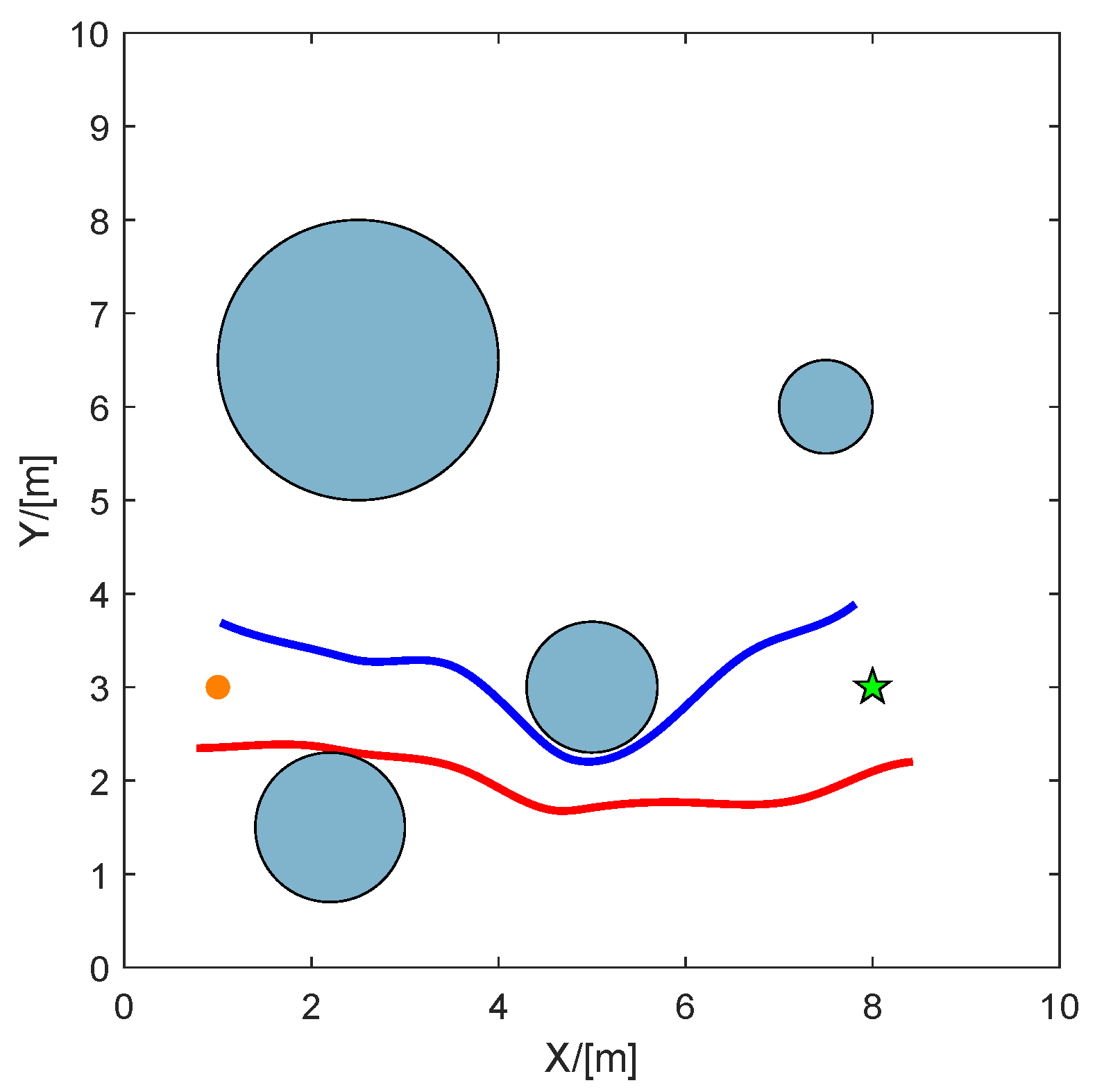
5.2. Virtual Tube Planning

In this part, the virtual tube is planned based on the PIO algorithm in an obstacle environment. Simulations are conducted with 20 UAVs in a 10 m × 10 m environment. The positions of the starting point, endpoint, and obstacles are shown in Table 2 below.
The simulation results are shown in Figure 14, where the orange circle and green star represent the starting point and endpoint, respectively. It can be observed that the tube’s boundaries obtained through PIO are smooth, providing a safe corridor for UAVs to pass through. The simulation snapshots, shown in Figure 15a–d, illustrate that all UAVs successfully passed through the planned virtual tube. Therefore, the results demonstrate the effectiveness of the proposed PIO-based virtual tube planning method.
Compared to other bio-inspired heuristic algorithms, the PIO algorithm offers greater advantages in virtual tube planning. As shown in Table 3, we compare the optimization performance of the particle swarm optimization (PSO), PIO, predator-prey pigeon-inspired optimization (PPPIO), and genetic algorithm (GA) in planning the generating curve of the virtual tube. While the PSO algorithm has the shortest running time, the generating curve is relatively long. Although the PPPIO algorithm produces the shortest path, the introduction of the predator–prey operator increases computational complexity, leading to a longer execution time. Therefore, in terms of feasibility and optimization performance, the PIO algorithm is more suitable for virtual tube planning than the other three classical bio-inspired swarm intelligence algorithms.
In the context of virtual tube planning, our previous work utilizes the A* algorithm [9] and the RRT* method [10] for path planning. The A* heuristic search algorithm is highly efficient in finding the shortest path in known environments. It uses a cost function that combines the actual cost from the start point and an estimated cost to the goal. However, its performance can degrade in high-dimensional spaces or when the heuristic is poorly designed. The RRT* algorithm, an incremental sampling-based approach, excels in handling complex environments. It asymptotically converges to the optimal solution but may require significant computational resources and time to achieve high precision. Therefore, this paper adopts the PIO algorithm for path planning, which offers several advantages in complex environments. Unlike the A* and RRT* methods, PIO does not require a predefined graph or discretization of the search space, making it more flexible and robust in complex environments. Additionally, PIO’s ability to escape local optima and its simplicity of implementation make it a powerful tool for path planning in such environments.

6. Conclusions

This paper proposes a novel framework for UAV swarm navigation in obstacle-dense environments by integrating curved virtual tube planning and pigeon-inspired flocking behaviors. The curved virtual tube planning method, based on pigeon-inspired optimization (PIO), ensures obstacle-free paths and adapts well to cluttered environments, overcoming the limitations of traditional methods. The distributed swarm controller, inspired by pigeon flocking hierarchical behaviors, guarantees collision avoidance, safe passage, and adherence to the virtual tube. Numerical simulations demonstrated the effectiveness of the proposed methods, showing that UAV swarms can navigate safely and efficiently through the virtual tube.
Future work will focus on optimizing the planning process for dynamic environments, incorporating real-time constraints. This work significantly advances UAV swarm navigation, offering a safer and more efficient framework for complex environments.

Author Contributions

Conceptualization, Y.L.; Methodology, Y.L. and Q.Q.; Formal analysis, Z.S.; Writing—original draft, Y.L.; Writing—review & editing, Z.S. and Q.Q.; Supervision, Q.Q.; Project administration, Q.Q.; Funding acquisition, Q.Q. All authors have read and agreed to the published version of the manuscript.

Funding

This work was supported in part by the National Natural Science Foundation of China under Grant 62450127.

Data Availability Statement

The original contributions presented in this study are included in the article. Further inquiries can be directed to the corresponding author.

Conflicts of Interest

The authors declare no conflicts of interest.

References

  1. Chung, S.; Paranjape, A.A.; Dames, P.; Shen, S.; Kumar, V. A survey on aerial swarm robotics. IEEE Trans. Robot. 2018, 34, 837–855. [Google Scholar] [CrossRef]
  2. Qi, J.; Guo, J.; Wang, M.; Wu, C.; Ma, Z. Formation tracking and obstacle avoidance for multiple quadrotors with static and dynamic obstacles. IEEE Robot. Autom. Lett. 2022, 7, 1713–1720. [Google Scholar] [CrossRef]
  3. Luis, C.; Schoellig, A. Trajectory generation for multiagent point-to-point transitions via distributed model predictive control. IEEE Robot. Autom. Lett. 2019, 4, 375–382. [Google Scholar] [CrossRef]
  4. Rezende, A.; Goncalves, V.; Pimenta, L. Constructive time-varying vector fields for robot navigation. IEEE Trans. Robot. 2021, 38, 852–867. [Google Scholar] [CrossRef]
  5. Quan, Q.; Fu, R.; Li, M.; Wei, D.; Gao, Y.; Cai, K.-Y. Practical distributed control for VTOL UAVs to pass a virtual tube. IEEE Trans. Intell. Veh. 2022, 7, 342–353. [Google Scholar] [CrossRef]
  6. Wang, L.; Ames, A.; Egerstedt, M. Safety barrier certificates for collisions-free multirobot systems. IEEE Trans. Robot. 2017, 33, 661–674. [Google Scholar] [CrossRef]
  7. Vásárhelyi, G.; Virágh, C.; Somorjai, G.; Nepusz, T.; Eiben, A.; Vicsek, T. Optimized flocking of autonomous drones in confined environments. Sci. Robot. 2018, 3, eaat3536. [Google Scholar] [CrossRef]
  8. Quan, Q.; Gao, Y.; Bai, C. Distributed control for a robotic swarm to pass through a curve virtual tube. Robot. Auton. Syst. 2023, 162, 104368. [Google Scholar] [CrossRef]
  9. Mao, P.; Quan, Q. Making robotics swarm flow more smoothly: A regular virtual tube model. In Proceedings of the 2022 IEEE/RSJ International Conference on Intelligent Robots and Systems (IROS), Kyoto, Japan, 23–27 October 2022; pp. 4498–4504. [Google Scholar]
  10. Mao, P.; Fu, R.; Quan, Q. Optimal virtual tube planning and control for swarm robotics. Int. J. Robot. Res. 2024, 43, 602–627. [Google Scholar] [CrossRef]
  11. Qiu, H.; Duan, H. Pigeon interaction mode switch-based UAV distributed flocking control under obstacle environments. ISA Trans. 2017, 71, 93–102. [Google Scholar] [CrossRef]
  12. Lin, Z.; Wu, K.; Shen, R.; Yu, X.; Huang, S. An efficient and accurate A-star algorithm for autonomous vehicle path planning. IEEE Trans. Veh. Technol. 2024, 73, 9003–9008. [Google Scholar] [CrossRef]
  13. Prasad, N.; Ramkumar, B. 3-D deployment and trajectory planning for relay based UAV assisted cooperative communication for emergency scenarios using Dijkstra’s algorithm. IEEE Trans. Veh. Technol. 2023, 72, 5049–5063. [Google Scholar] [CrossRef]
  14. Wang, J.; Chi, W.; Li, C.; Wang, C.; Meng, M. Neural RRT*: Learning-based optimal path planning. IEEE Trans. Autom. Sci. Eng. 2020, 17, 1748–1758. [Google Scholar] [CrossRef]
  15. Zhang, Z.; Jiang, J.; Ling, K.; Zhang, W. Real-Time Path Planning for Autonomous UAVs: An Event-Triggered Multimodal Adaptive Pigeon-Inspired Optimization Approach. IEEE Trans. Aerosp. Electron. Syst. 2025. [Google Scholar] [CrossRef]
  16. Li, Y.; Zhang, L.; Cai, B.; Liang, Y. Unified path planning for composite UAVs via Fermat point-based grouping particle swarm optimization. Aerosp. Sci. Technol. 2024, 148, 109088. [Google Scholar] [CrossRef]
  17. Wu, L.; Huang, X.; Cui, J.; Liu, C.; Xiao, W. Modified adaptive ant colony optimization algorithm and its application for solving path planning of mobile robot. Expert Syst. Appl. 2023, 215, 119410. [Google Scholar] [CrossRef]
  18. Zheng, J.; Ding, M.; Sun, L.; Liu, H. Distributed stochastic algorithm based on enhanced genetic algorithm for path planning of multi-UAV cooperative area search. IEEE Trans. Intell. Transp. Syst. 2023, 24, 8290–8303. [Google Scholar] [CrossRef]
  19. Duan, H.; Qiao, P. Pigeon-inspired optimization: A new swarm intelligence optimizer for air robot path planning. Int. J. Intell. Comput. Cybern. 2014, 7, 24–37. [Google Scholar] [CrossRef]
  20. Zhang, D.; Duan, H. Social-class pigeon-inspired optimization and time stamp segmentation for multi-UAV cooperative path planning. Neurocomputing 2018, 313, 229–246. [Google Scholar] [CrossRef]
  21. Duan, H.; Zhao, J.; Deng, Y.; Shi, Y.; Ding, X. Dynamic discrete pigeon-inspired optimization for multi-UAV cooperative search-attack mission planning. IEEE Trans. Aerosp. Electron. Syst. 2020, 57, 706–720. [Google Scholar] [CrossRef]
  22. Song, W.; Gao, Y.; Quan, Q. Speed and density planning for a speed-constrained robot swarm through a virtual tube. IEEE Robot. Autom. Lett. 2024, 9, 10628–10635. [Google Scholar] [CrossRef]
  23. Zhao, J.; Duan, H.; Chen, L.; Huo, M. Leadership hierarchy-based formation control via adaptive chaotic pigeon-inspired optimization. IFAC-PapersOnLine 2020, 53, 9348–9353. [Google Scholar] [CrossRef]
Figure 1. Virtual tube example, the purple and blue polyhedrons are terminals. The shaded polyhedrons are cross-sections C t . The black curve is a trajectory from q 0 in terminal C 0 to q m in terminal C 1 . The gray area is the virtual tube.
Drones 09 00333 g001
Figure 2. Landmark operator process.
Drones 09 00333 g002
Figure 3. Virtual tube planning process.
Drones 09 00333 g003
Figure 4. Pigeon hierarchical leadership network.
Drones 09 00333 g004
Figure 5. Pigeon hierarchical leadership network.
Drones 09 00333 g005
Figure 6. Simulation snapshots based on the proposed method: (a) 1 s. (b) 4.5 s. (c) 8 s. (d) 11 s.
Drones 09 00333 g006
Figure 7. Minimum distance among UAVs with respect to time-based on the proposed control method.
Drones 09 00333 g007
Figure 8. Minimum distance from tube boundary with respect to time-based on the proposed control method.
Drones 09 00333 g008
Figure 9. Flight trajectories of UAV swarm based on the proposed control method.
Drones 09 00333 g009
Figure 10. Simulation snapshots based on the flocking method: (a) 1 s. (b) 4.5 s. (c) 8 s. (d) 12 s.
Drones 09 00333 g010
Figure 11. Minimumdistance among UAVs with respect to time-based on the flocking method.
Drones 09 00333 g011
Figure 12. Minimum distance from tube boundary with respect to time-based on the flocking method.
Drones 09 00333 g012
Figure 13. Flight trajectories of UAV swarm based on the flocking method.
Drones 09 00333 g013
Figure 14. Virtual tube planning based on PIO.
Drones 09 00333 g014
Figure 15. Simulation snapshots based on the virtual tube planning method: (a) 0 s. (b) 0.5 s. (c) 1.5 s. (d) 4 s.
Drones 09 00333 g015
Table 1. Hierarchical parameter settings for UAV swarm.
TypeLevelNumberSet of Leaders Number
Leader1
Followersfirst-level2, 3, 41
second-level51, 2
61, 3
71, 4
third-level81, 2, 5
91, 3, 6
101, 4, 7
Table 2. Parameter settings for virtual tube planning.
Starting PointEndpointObstacle 1Obstacle 2Obstacle 3Obstacle 4
Position ( x , y ) 182.552.27.5
336.531.56
Radius1.50.80.80.5
Dimension ( m ) .
Table 3. Performance analysis of different bio-inspired heuristic optimization algorithms.
PSOPIOPPPIOGA
Path length (m)8.0377.1177.0139.282
Running time (s)1.2161.5361.7041.449
Disclaimer/Publisher’s Note: The statements, opinions and data contained in all publications are solely those of the individual author(s) and contributor(s) and not of MDPI and/or the editor(s). MDPI and/or the editor(s) disclaim responsibility for any injury to people or property resulting from any ideas, methods, instructions or products referred to in the content.

