
Evaluation of Aerodynamic Performance of a Multi-Rotor eVTOL During Landing Using the Lattice Boltzmann Method


Abstract
1. Introduction
2. Numerical Methodology
2.1. Lattice Boltzmann Method
- Collision Process:
- b.
- Propagation Process:
2.2. Turbulent Model
2.3. Wall Treatment
2.4. Setting
2.5. Mesh
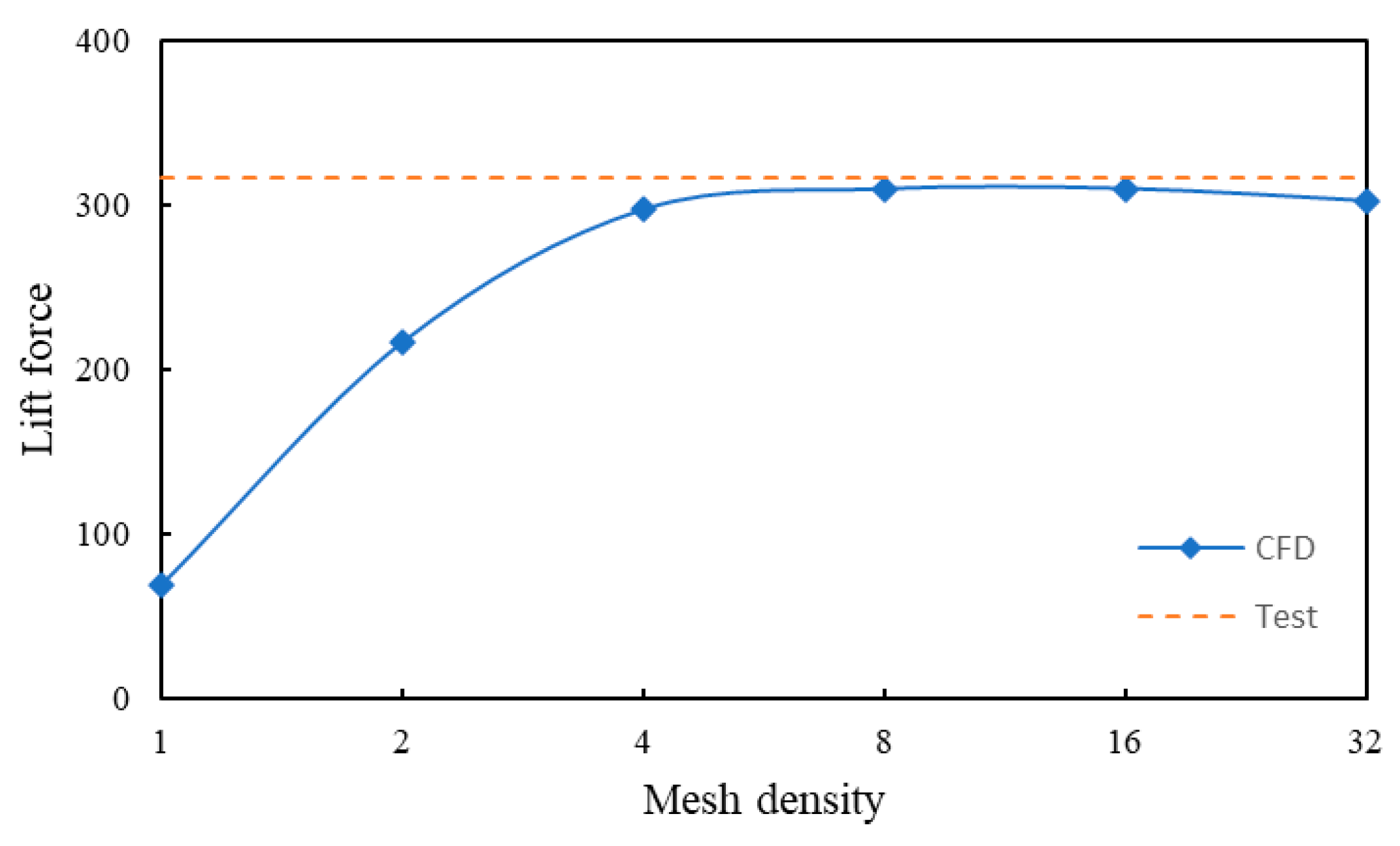
2.6. Validation
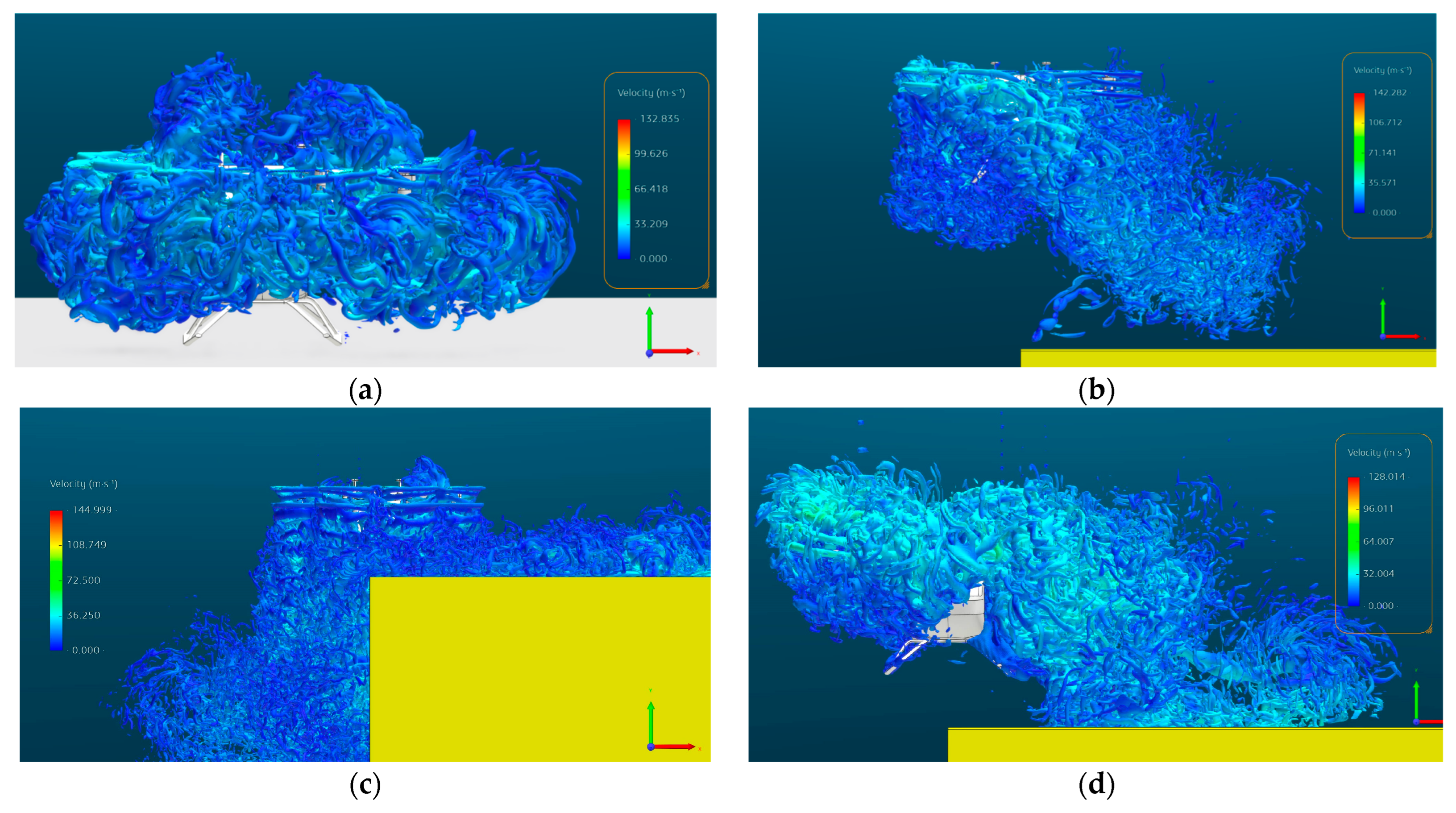
3. Results and Discussion
4. Conclusions
- The ground effect significantly increases lift force by approximately 13% compared to free-air conditions.
- Higher descent speeds and the presence of crosswinds further amplifies lift forces, with the combined effect of a 3 m/s descent speed and 10 m/s crosswind resulting in a 6.7% increase in lift.
- Asymmetric lift distribution, due to the interaction between crosswinds and roof-induced flow circulation, leads to a substantial decrease in the lift on the rotors above the roof and an increase in rolling moment.
Author Contributions
Funding
Data Availability Statement
Conflicts of Interest
References
- Vascik, P.D.; Hansman, R.J. Scaling constraints for urban air mobility operations: Air traffic control, ground infrastructure, and noise. In Proceedings of the 2018 Aviation Technology, Integration, and Operations Conference, Atlanta, GA, USA, 25–29 June 2018; p. 3849. [Google Scholar]
- Sengupta, R.; Bulusu, V.; Mballo, C.E.; Onat, E.B.; Cao, S. Urban Air Mobility Research Challenges and Opportunities. Annu. Rev. Control. Robot. Auton. Syst. 2025, 8. [Google Scholar] [CrossRef]
- Cohen, A.P.; Shaheen, S.A.; Farrar, E.M. Urban air mobility: History, ecosystem, market potential, and challenges. IEEE Trans. Intell. Transp. Syst. 2021, 22, 6074–6087. [Google Scholar] [CrossRef]
- Matus-Vargas, A.; Rodriguez-Gomez, G.; Martinez-Carranza, J. Ground effect on rotorcraft unmanned aerial vehicles: A review. Intell. Serv. Robot. 2021, 14, 99–118. [Google Scholar] [CrossRef]
- Chae, S.; Lee, S.; Hwang, S.; Jeong, S.; Kim, J. Effects of rotor–rotor interaction for a small tandem rotor operating in a crosswind. Phys. Fluids 2024, 36, 065147. [Google Scholar] [CrossRef]
- Hu, L.; Yan, X.; Yuan, Y. Development and challenges of autonomous electric vertical take-off and landing aircraft. Heliyon 2025, 11, e41055. [Google Scholar] [CrossRef] [PubMed]
- Higgins, R.J.; Barakos, G.N.; Shahpar, S.; Tristanto, I. A computational fluid dynamic acoustic investigation of a tiltwing eVTOL concept aircraft. Aerosp. Sci. Technol. 2021, 111, 106571. [Google Scholar] [CrossRef]
- Sharma, K.V.; Straka, R.; Tavares, F.W. Current status of Lattice Boltzmann Methods applied to aerodynamic, aeroacoustic, and thermal flows. Prog. Aerosp. Sci. 2020, 115, 100616. [Google Scholar] [CrossRef]
- Hendricks, E.S.; Falck, R.D.; Gray, J.S.; Aretskin-Hariton, E.; Ingraham, D.; Chapman, J.W.; Schnulo, S.L.; Chin, J.; Jasa, J.P.; Bergeson, J.D. Multidisciplinary optimization of a turboelectric tiltwing urban air mobility aircraft. In Proceedings of the AIAA Aviation 2019 Forum, Dallas, TX, USA, 17–21 June 2019; p. 3551. [Google Scholar]
- Bludau, J.; Rauleder, J.; Friedmann, L.; Hajek, M. Real-time simulation of dynamic inflow using rotorcraft flight dynamics coupled with a lattice-Boltzmann based fluid simulation. In Proceedings of the 55th AIAA Aerospace Sciences Meeting, Grapevine, TX, USA, 9–13 January 2017; p. 0050. [Google Scholar]
- Krüger, T.; Kusumaatmaja, H.; Kuzmin, A.; Shardt, O.; Silva, G.; Viggen, E.M. The Lattice Boltzmann Method; Springer International Publishing: Berlin/Heidelberg, Germany, 2017; pp. 4–15. [Google Scholar]
- Chen, S.; Doolen, G.D. Lattice Boltzmann method for fluid flows. Annu. Rev. Fluid Mech. 1998, 30, 329–364. [Google Scholar] [CrossRef]
- Thürey, N.; Iglberger, K.; Rüde, U. Free surface flows with moving and deforming objects for LBM. In Proceedings of the Vision, Modeling and Visualization, Aachen, Germany, 22–24 November 2006; pp. 193–200. [Google Scholar]
- Strack, O.E.; Cook, B.K. Three-dimensional immersed boundary conditions for moving solids in the lattice-Boltzmann method. Int. J. Numer. Methods Fluids 2007, 55, 103–125. [Google Scholar] [CrossRef]
- Zhang, H.; Qi, L.; Wu, Y.; Musiu, E.M.; Cheng, Z.; Wang, P. Numerical simulation of airflow field from a six–rotor plant protection drone using lattice Boltzmann method. Biosys. Eng. 2020, 197, 336–351. [Google Scholar] [CrossRef]
- Chang, K.; Chen, S.; Wang, M.; Xue, X.; Lan, Y. Numerical simulation and verification of rotor downwash flow field of plant protection UAV at different rotor speeds. Front. Plant Sci. 2023, 13, 1087636. [Google Scholar] [CrossRef] [PubMed]
- Cheeseman, I.; Bennett, W. The Effect of the Ground on a Helicopter Rotor in Forward Flight; Cranfield University: Bedford, UK, 1955. [Google Scholar]
- Sanchez-Cuevas, P.J.; Heredia, G.; Ollero, A. Experimental approach to the aerodynamic effects produced in multirotors flying close to obstacles. In Advances in Intelligent Systems and Computing, Proceedings of ROBOT 2017: Third Iberian Robotics Conference, Sevilla, Spain, 22–24 November 2017; Springer: Berlin/Heidelberg, Germany, 2018; Volume 1, pp. 742–752. [Google Scholar]
- Powers, C.; Mellinger, D.; Kushleyev, A.; Kothmann, B.; Kumar, V. Influence of aerodynamics and proximity effects in quadrotor flight. In Springer Tracts in Advanced Robotics, Proceedings of Experimental Robotics: The 13th International Symposium on Experimental Robotics, Quebec, Canada, 18–21 June 2012; Springer: Berlin/Heidelberg, Germany, 2013; pp. 289–302. [Google Scholar]
- Sharf, I.; Nahon, M.; Harmat, A.; Khan, W.; Michini, M.; Speal, N.; Trentini, M.; Tsadok, T.; Wang, T. Ground effect experiments and model validation with Draganflyer X8 rotorcraft. In Proceedings of the 2014 International Conference on Unmanned Aircraft Systems (ICUAS), Orlando, FL, USA, 27–30 May 2014; pp. 1158–1166. [Google Scholar]
- Li, H.; Dong, X.; Gao, Y.; Liu, Y.; Bie, D.; Li, D.; Xiang, J.; Tu, Z. Numerical analysis on the ducted propeller aerodynamics in sidewall-ground effect. Phys. Fluids 2024, 36, 125148. [Google Scholar] [CrossRef]
- Ding, M.; Zhang, Y.; Zhu, S.; Song, W.; Zhao, P.; Yan, X.; Cai, J.; Gu, J.; Xie, A. Aerodynamic Simulation of a Typical Multirotor eVTOL Aircraft Configuration. In Proceedings of the 2022 IEEE International Conference on Robotics and Biomimetics (ROBIO), Jinghong, China, 5–9 December 2022; pp. 765–769. [Google Scholar]
- Tugnoli, M.; Montagnani, D.; Syal, M.; Droandi, G.; Zanotti, A. Mid-fidelity approach to aerodynamic simulations of unconventional VTOL aircraft configurations. Aerosp. Sci. Technol. 2021, 115, 106804. [Google Scholar] [CrossRef]
- Wentrup, M.; Yin, J.; Kunze, P.; Streit, T.; Wendisch, J.-H.; Schwarz, T.; Pinacho, J.-P.; Kicker, K.; Fukari, R. An overview of DLR compound rotorcraft aerodynamics and aeroacoustics activities within the CleanSky2 NACOR Project. In Proceedings of the AHS Forum, Phoenix, AZ, USA, 14–17 May 2018. [Google Scholar]
- Tan, J.F.; Zhou, T.Y.; Sun, Y.M.; Barakos, G.N. Numerical investigation of the aerodynamic interaction between a tiltrotor and a tandem rotor during shipboard operations. Aerosp. Sci. Technol. 2019, 87, 62–72. [Google Scholar] [CrossRef]
- Cottet, G.-H.; Koumoutsakos, P.D. Vortex Methods: Theory and Practice; Cambridge University Press: Cambridge, UK, 2000; Volume 313. [Google Scholar]
- Shih, T.-H. A Generalized Wall Function; National Aeronautics and Space Administration, Glenn Research Center: Cleveland, OH, USA, 1999. [Google Scholar]
- Dassault. XFlow. Available online: https://www.3ds.com/products/simulia/xflow (accessed on 20 March 2025).
- Holman, D.M.; Brionnaud, R.M.; Abiza, Z. Solution to industry benchmark problems with the lattice-Boltzmann code XFlow. Proceeding of the European Congress on Computational Methods in Applied Sciences and Engineering (ECCOMAS), Vienna, Austria, 10–14 September 2012; pp. 1–16. [Google Scholar]
- Tmotor.com. U15L KV43. Available online: https://uav-cn.tmotor.com/2019/MannedAircraft_0703/276.html (accessed on 26 March 2025).


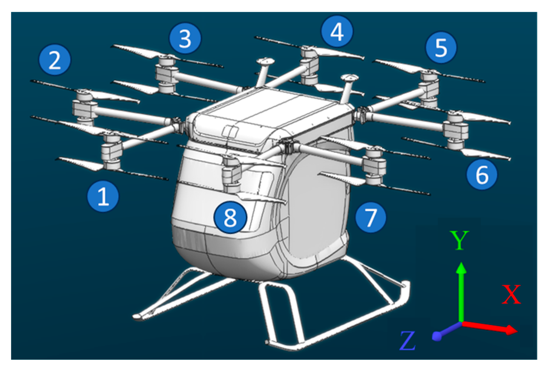
| Axis ID | X (m) | Z (m) |
|---|---|---|
| 1 | −0.648 | 1.564 |
| 2 | −1.564 | 0.648 |
| 3 | −1.564 | −0.648 |
| 4 | −0.648 | −1.564 |
| 5 | 0.648 | −1.564 |
| 6 | 1.564 | −0.648 |
| 7 | 1.564 | 0.648 |
| 8 | 0.648 | 1.564 |
| Gas Properties | Value |
|---|---|
| Molecular weight | 29 |
| Density | 1.2 kg/m3 |
| Temperature | 288 K |
| Viscosity coefficient | 1.8 × 10⁻⁵ Pa·s |
| Thermal conductivity | 0.024 W/(m·K) |
| Specific heat capacity | 1006.4 J/(kg·K) |
| Validation Case | Velocity (m/s) | Pitch Angle (deg) | Rotational Speed (deg/s) | |||
|---|---|---|---|---|---|---|
| Axis 1 and 8 | Axis 2 and 7 | Axis 3 and 6 | Axis 4 and 5 | |||
| 1 | 0 | 0 | 14,364 | 14,364 | 14,364 | 14,364 |
| 2 | 4 | −1 | 13,068 | 13,716 | 14,364 | 14,724 |
| 3 | 6 | −2.5 | 11,664 | 13,068 | 14,401 | 15,300 |
| Validation Case | Lift Force (N) | Weight (N) | Error (%) |
|---|---|---|---|
| 1 | 3689.1 | 3668.9 | 0.6 |
| 2 | 3465.8 | 5.5 | |
| 3 | 3316.7 | 9.6 |
| Case | Landing Area | Descent Speed (m/s) | Crosswind Speed (m/s) | Lift Force—Right Side (N) | Lift Force—Left Side (N) | Lift Force (N) | Variation (%) | Rolling Moment—Right Side (N·m) | Rolling Moment—Left Side (N·m) | Rolling Moment (N·m) |
|---|---|---|---|---|---|---|---|---|---|---|
| 1 | Ground | 0 | 0 | - | - | 4073.7 | - | - | - | - |
| 2 | 1.5 | 0 | - | - | 4112.1 | 0.9 | - | - | - | |
| 3 | 1.5 | 10 | - | - | 4224.7 | 3.7 | - | - | - | |
| 4 | 3 | 0 | - | - | 4297.3 | 5.5 | - | - | - | |
| 5 | 3 | 10 | 2138.1 | 1834.7 | 4348.0 | 6.7 | −2420.8 | 2040.1 | −380.6 | |
| 6 | Roof | 0 | 0 | 1972.1 | 1987.8 | 3779.6 | −7.2 | −2179.6 | 2201.0 | 21.4 |
| 7 | 0 | 10 | 2233.2 | 1498.9 | 3754.0 | −7.8 | −2492.3 | 1745.1 | −747.2 | |
| 8 | 3 | 0 | 2037.5 | 2047.6 | 4089.2 | 0.4 | −2254.3 | 2263.7 | 9.4 | |
| 9 | 3 | 10 | 2729.1 | 1695.1 | 4284.6 | 5.2 | −3083.4 | 1949.4 | −1134.0 |
Disclaimer/Publisher’s Note: The statements, opinions and data contained in all publications are solely those of the individual author(s) and contributor(s) and not of MDPI and/or the editor(s). MDPI and/or the editor(s) disclaim responsibility for any injury to people or property resulting from any ideas, methods, instructions or products referred to in the content. |
© 2025 by the authors. Licensee MDPI, Basel, Switzerland. This article is an open access article distributed under the terms and conditions of the Creative Commons Attribution (CC BY) license (https://creativecommons.org/licenses/by/4.0/).
Share and Cite
Ding, M.; Li, H.; Shao, L.; Xuan, J.; Feng, C.; Yan, X.; Bie, D. Evaluation of Aerodynamic Performance of a Multi-Rotor eVTOL During Landing Using the Lattice Boltzmann Method. Drones 2025, 9, 332. https://doi.org/10.3390/drones9050332
Ding M, Li H, Shao L, Xuan J, Feng C, Yan X, Bie D. Evaluation of Aerodynamic Performance of a Multi-Rotor eVTOL During Landing Using the Lattice Boltzmann Method. Drones. 2025; 9(5):332. https://doi.org/10.3390/drones9050332
Chicago/Turabian StyleDing, Menglong, Huadong Li, Lintao Shao, Jinting Xuan, Chuanyan Feng, Xufei Yan, and Dawei Bie. 2025. "Evaluation of Aerodynamic Performance of a Multi-Rotor eVTOL During Landing Using the Lattice Boltzmann Method" Drones 9, no. 5: 332. https://doi.org/10.3390/drones9050332
APA StyleDing, M., Li, H., Shao, L., Xuan, J., Feng, C., Yan, X., & Bie, D. (2025). Evaluation of Aerodynamic Performance of a Multi-Rotor eVTOL During Landing Using the Lattice Boltzmann Method. Drones, 9(5), 332. https://doi.org/10.3390/drones9050332