7.1. Aerodynamic Model
Refs. [
13,
14] describe QuadPlane aerodynamic coefficients from wind tunnel data at test vehicle angles of attack
, over normalized control surface deflections
at test airspeeds
= {5 m/s, 11 m/s, 15 m/s}. Note that the QuadPlane wing is mounted at an angle of incidence
relative to the fuselage such that the wing angle of attack
. This section denotes airspeed
as
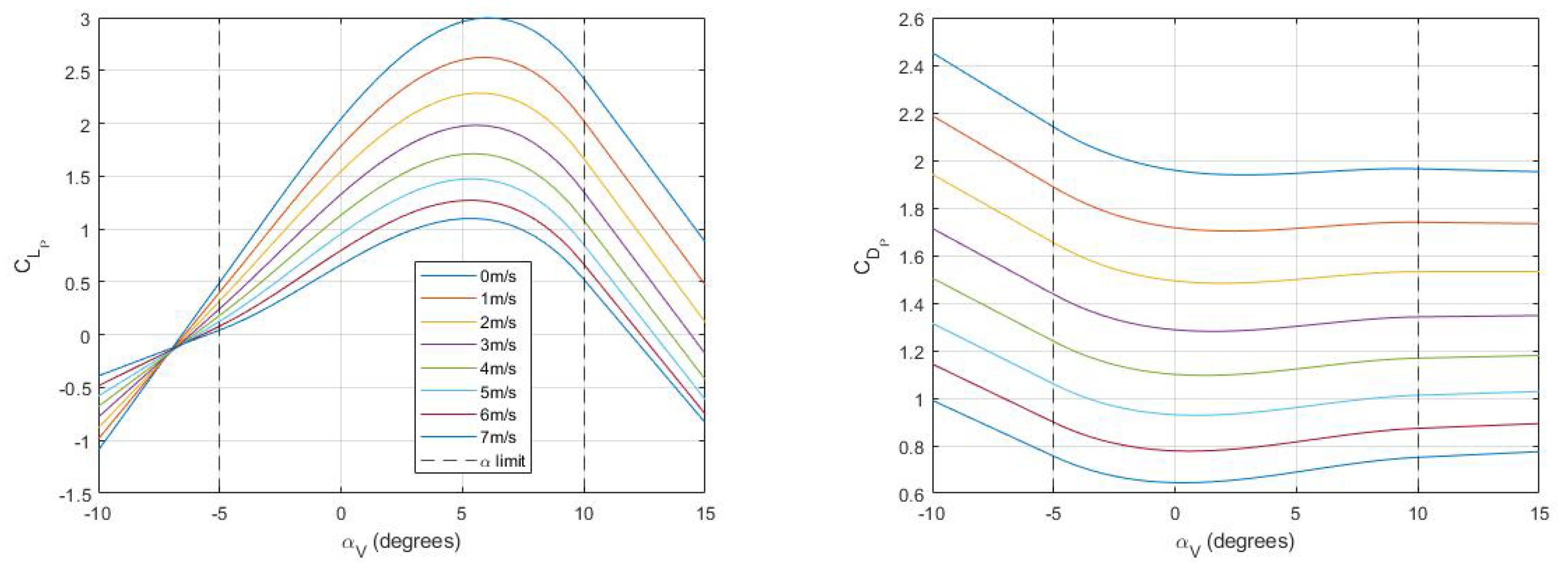
V for simplicity. To compute aerodynamic coefficients at intermediate airspeeds, angles of attack, and control surface deflections, surface-fit raw experimental coefficient data was analyzed and plotted in
Figure 4. Here, the
x-axis represents vehicle angle of attack
for stability derivatives and normalized control surface deflection
for control derivatives. The
y-axis shows airspeed while the
z-axis shows the given coefficient value. Polynomial surface fits
poly32 of third degree in
x and second degree in
y were used for each aerodynamic coefficient:
This formulation allows for convenient interpolation and extrapolation of data beyond the tested values. The
poly32 fit with nine parameters captures the trends, well as shown in
Figure 4, but does not overfit the data since we have 12 experimental data points for the stability derivatives and 15 data points for control derivatives from [
14]. Derived polynomial coefficient parameters for all 3D surface fits in each flight mode are tabulated in
Table 3. The coefficients
and
are common across all three flight modes;
,
,
,
, and
are common among the Plane and Hybrid mode; and the remaining coefficients are unique to each referenced flight mode. Note that the coefficient of lift
for each flight mode is modeled as a cubic function of
to additionally capture wing stall and post-stall behavior.
as a function of
is predominantly quadratic, so the corresponding cubic fit parameter
is negligible for all three flight modes per
Table 3. All control derivatives show linear dependence on control surface deflection.
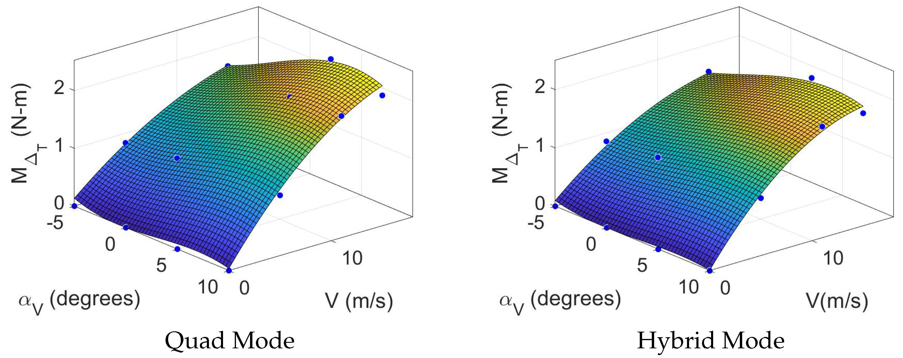
is a unique stability derivative for Quad and Hybrid modes, analogous to
for aircraft. This parameter represents the pitching moment from vertical propulsion as a function of
V and
and differs in that it is not scaled by airspeed (
V) but instead represents direct pitching moment application arising from differential thrust from front and rear vertical propulsors while there is airflow along the body
x-axis as described in [
14].
is zero at zero airspeed. Therefore, four additional data points are added to the data from [
14] where
at each tested
value, as shown in
Figure 5. This moment becomes zero as the vertical propulsors stop spinning, so we implement this moment in simulation as a total thrust reduction in
for the rear vertical motors. For each rear motor, thrust is reduced by
.
For full multi-mode flight simulation, we require data outside of the experimentally acquired values, especially for operating at 0 m/s
5 m/s in Quad mode. As most aerodynamic coefficients are scaled by
, we must extrapolate surface fits to compute values down to
V = 0 m/s. The maximum achievable QuadPlane airspeed of
m/s is set as the upper limit for extrapolation. We also extrapolate normalized control surface deflections
to support a normalized range of values between
and 1.
Table 4 lists airspeed, thrust, sideslip, and normalized control surface deflection limits across all three flight modes for all simulation studies in this paper.
The
range over which aerodynamic data is available [
] is also restrictive for real-world flight conditions, especially in Quad mode. For instance, as can be seen in
Section 7.3, for the QuadPlane to fly at an airspeed of 5 m/s in Quad mode, an
of nearly
is required. To extrapolate
values, a tangent is generated on the 2D curve derived by splicing the 3D fit surface at a given
V with the value of the coefficient on the tangent at the desired
.
Figure 6 shows the resulting extrapolation. Note that we do not have any aerodynamic data for vertical flight, so we assume aerodynamic forces are negligible for
1 m/s when
or
and restrict vertical speed in all simulations to less than 1 m/s.
Aerodynamic forces and moments can be calculated from aerodynamic coefficients in the wind frame for a given flight mode. However, the experimental data in [
13] is only available for
. Instead of ignoring forces and moments in the presence of crosswinds, we use the dimensions of the vertical stabilizer and approximate it as a finite wing with chord
and area
with a NACA 0006 airfoil [
50]. NACA data is used to define aerodynamic coefficient of lift
and pitching moment
for the vertical stabilizer as described previously in [
12]. We then compute the lift and pitching moment on the vertical stabilizer for a given sideslip angle. Note that the angle of attack for the vertical stabilizer is the sideslip angle for the aircraft. The net aerodynamic forces and moments on the aircraft in the wind frame are then given by
where
denotes the dynamic pressure, and coefficients
,
are derived from NACA data. Based on the flight mode, aerodynamic coefficient values are computed for the remaining terms in Equation (
22) to estimate net aerodynamic forces and moments. Forces and moments were then rotated from wind to body frame with
to apply body frame dynamics from Equation (
1). Note that the stall speed for the QuadPlane was determined to be 11.9 m/s using the aerodynamic model for Plane mode.
7.2. Propulsion Model
The QuadPlane experiences forces
and moments
from its four vertical thrusters and one forward thrust module:
where
and
are torque coefficients for the forward and vertical thrust modules, respectively, and
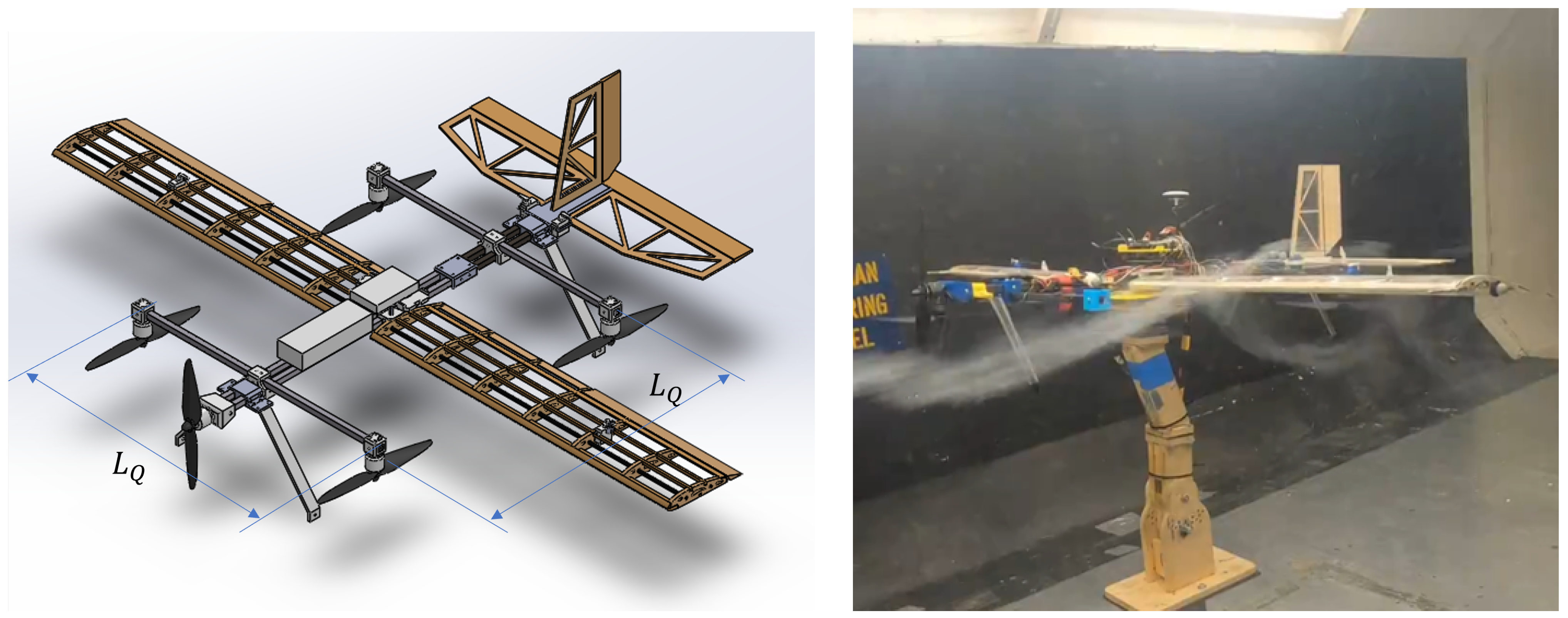
is the length of the quadrotor square [
21]. Together with Equation (
22), the total force and moment on the aircraft in the body frame can be computed and used in Equation (
1) to propagate the aircraft state. In Quad mode,
as the forward thrust module is inactive, while in Plane mode,
since the vertical thrusters are inactive.
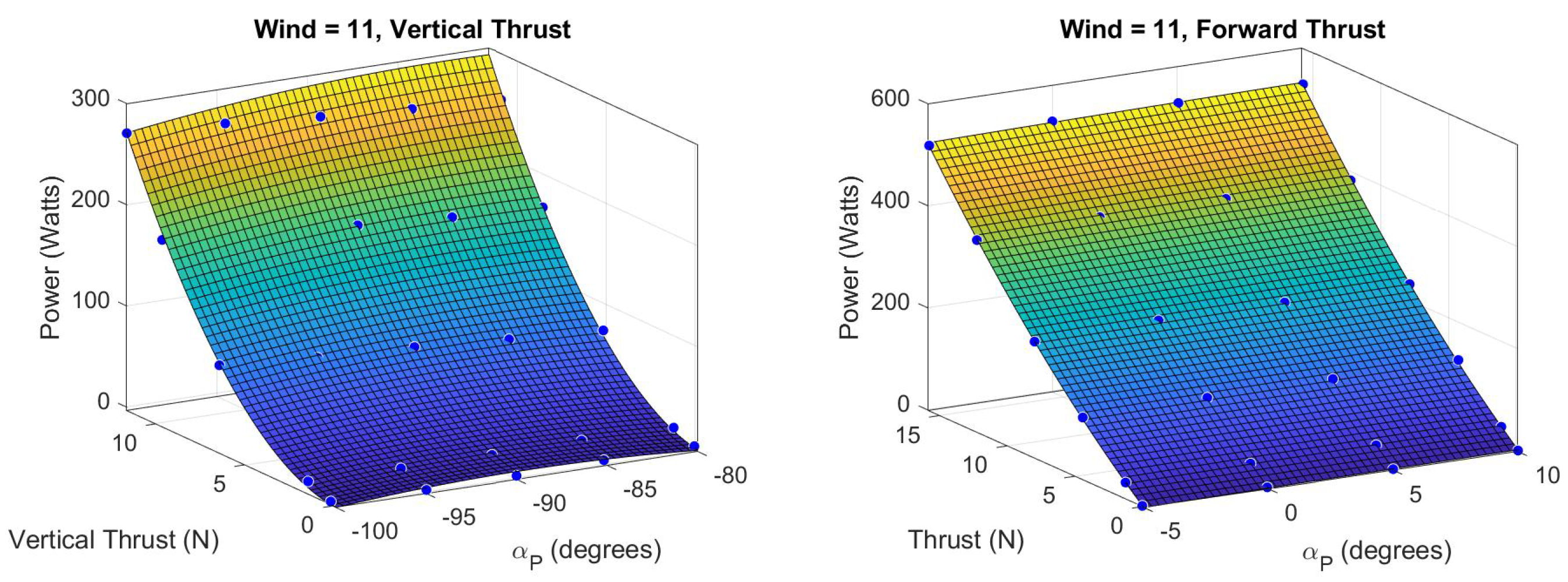
Propulsion system test data from [
14] was used to derive a 3D surface mapping between the propeller angle of attack
, thrust force, and power consumption over the four test airspeeds (
V = 0, 5, 11, 15 m/s) for both vertical and forward thrust modules. The propeller angle of attack for the front motor is the same as the aircraft angle of attack (
) and is offset by
for the vertical motors (
). The thrust from the forward thrust module used in [
13,
14] was found to be insufficient to overcome drag and maintain steady level flight at airspeeds greater than 11 m/s, maxing out at
at 15 m/s. A new, more powerful E-flite Power 25 motor and a larger
propeller were installed, and propulsion tests were repeated using the methods from [
14]. Surface fits for vertical and forward thrust modules at test airspeed
V = 11 m/s are shown in
Figure 7. For any desired thrust, power consumption is derived with linear interpolation from the two closest test airspeeds.
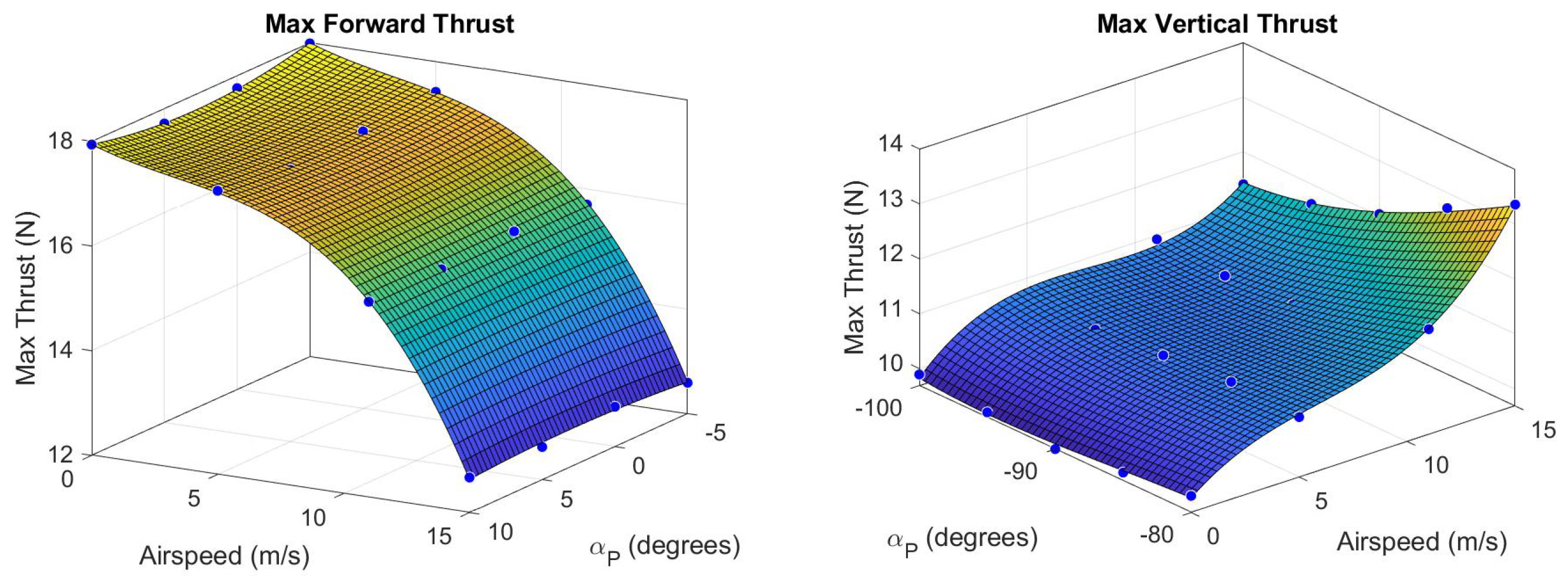
Maximum vertical thrust
and forward thrust
were determined as a function of
V and
and are shown in
Figure 8. These surfaces define commanded thrust saturation limits in simulation. Notice the drop in maximum forward thrust at higher airspeeds due to increased propeller drag and weathervaning. Note also an increase in vertical thrust, especially for
, as propeller thrust becomes aligned with propeller drag.
7.3. Trim States
Trim states are equilibrium aircraft configurations useful for steady state flight and control design. The nonlinear system of equations governing aircraft dynamics can be linearized about a trim state such that the derived linear system is a close approximation of the dynamics within the region of attraction. Computation of trim states for the QuadPlane across all flight modes is described here. Trim and propulsion models in turn support power consumption, range, and endurance estimation.
A lookup table for trim state solutions in each flight mode
M over an achievable airspeed range was constructed. This table provides the trim state (
) and corresponding control vectors (
) for a given cruise airspeed. For Hybrid mode, an additional entry for trim pitch angle
is provided. To derive the trim state for each airspeed in the lookup table, a distinct cost function is defined for each flight mode as described in the following paragraphs. The MATLAB R2024a
function is then used with a Sequential Quadratic Programming (SQP) algorithm to minimize the cost function within a step tolerance of
and constraint tolerance of
. Bounds and constraints for steady level flight trim states are listed in
Table 5. Note that
denote the angular aileron, elevator and rudder deflections respectively.
In Quad mode, a trivial trim state for hover (
V = 0 m/s) can be obtained by simple force balance with zero pitch and roll, where aircraft weight is equally distributed across the four vertical thrust motors. The aircraft must maintain a negative trim pitch angle for level flight at a given airspeed to counter drag. Determining Quad mode trim pitch angles across operational airspeeds is crucial for the design of
and
transition controllers to enable smooth pitch tracking over transitions. The cost function for Quad mode penalizes vertical thrust and is given below with
defining a diagonal 4 × 4 matrix:
In Plane mode, forward thrust and elevator deflection govern the trim pitch angle for the aircraft at a given airspeed. The cost function for Plane mode penalizes vertical velocity
, translational accelerations
, rotational velocities
and rotational accelerations
, in addition to the forward thrust
. Cost is defined below; note that the cost penalty for forward thrust is large to minimize power consumption for each trim state.
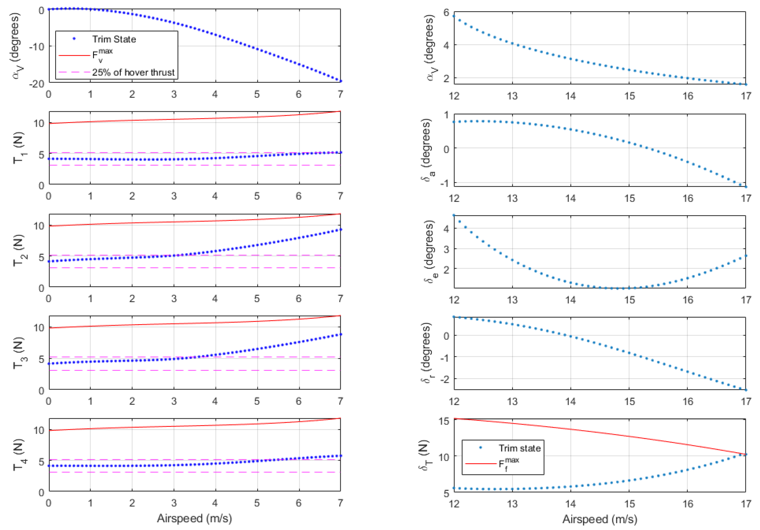
Figure 9 shows trim control inputs and pitch angle as a function of airspeed for Quad mode (left) and Plane mode (right). Dashed pink lines show a
thrust band around the vertical hover thrust, while solid red lines show maximum thrust at the given airspeed and pitch angle. The trim pitch angle is equivalent to
for steady-level flight. Quad mode trim pitch becomes increasingly negative for higher airspeeds. Vertical thrust trends are as expected for forward flight in Quad mode with negative pitch angles. The QuadPlane has a sufficient safety margin between the required and maximum vertical thrust at the Quad mode airspeed limit of 7 m/s. In Plane mode, the required forward thrust increases with increasing airspeed, as expected. Plane mode trim states require slight deflections of the aileron and rudder to balance the p-factor rolling moment generated by the forward thrust module. At an airspeed of 16.9 m/s, the forward thrust required approaches the maximum thrust line, i.e., the maximum achievable trim airspeed for the aircraft is 16.9 m/s. As expected, the angle of attack at lower airspeeds is higher to maximize lift and drops as airspeed increases to reduce drag as forward thrust becomes the limiting factor.
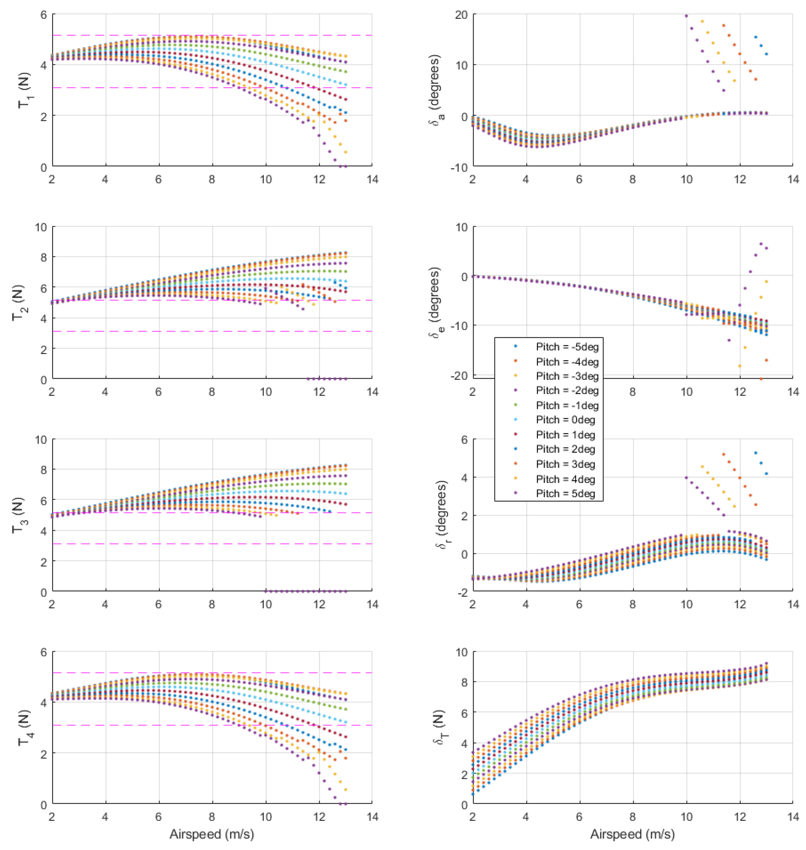
The cost function for Hybrid mode penalizes all thrust values, with a relatively low penalty for forward thrust to encourage acceleration to Plane speed. The cost penalty for elevator deflection is set high to prevent saturation, offloading most of the pitching moment compensation to differential vertical thrust. Hybrid mode trim states are computed across a range of feasible pitch angles.
Figure 10 shows trim states for the QuadPlane as a function of airspeed across pitch angles of
to
in
increments. This range was selected to cover Quad trim pitch angles up to airspeeds of 3.5 m/s and Plane mode trim pitch angles. Forward thrust increases with airspeed, as expected. At Plane mode cruise airspeed of 12.5 m/s, a forward thrust of
is required to maintain trim flight in Hybrid mode as opposed to
in Plane mode, as seen in
Figure 9. This excess forward thrust is required to counter the excess drag created by the spinning vertical thrust propellers in Hybrid mode. Notice that thrust from rear left motor
drops to zero beyond airspeeds of 10 m/s for
, 10.5 m/s for
, 11 m/s for
, and 12 m/s for
. This occurs because wing lift increasingly supports weight as airspeed and pitch angle increase. The rear left motor turns off first due to a p-factor rolling moment from the front motor. Once
, step changes in the remaining control inputs are required to stabilize the aircraft and maintain trim flight. In summary, Hybrid mode offers the largest operating envelope using any combination of airspeed and pitch angle in
Figure 10.
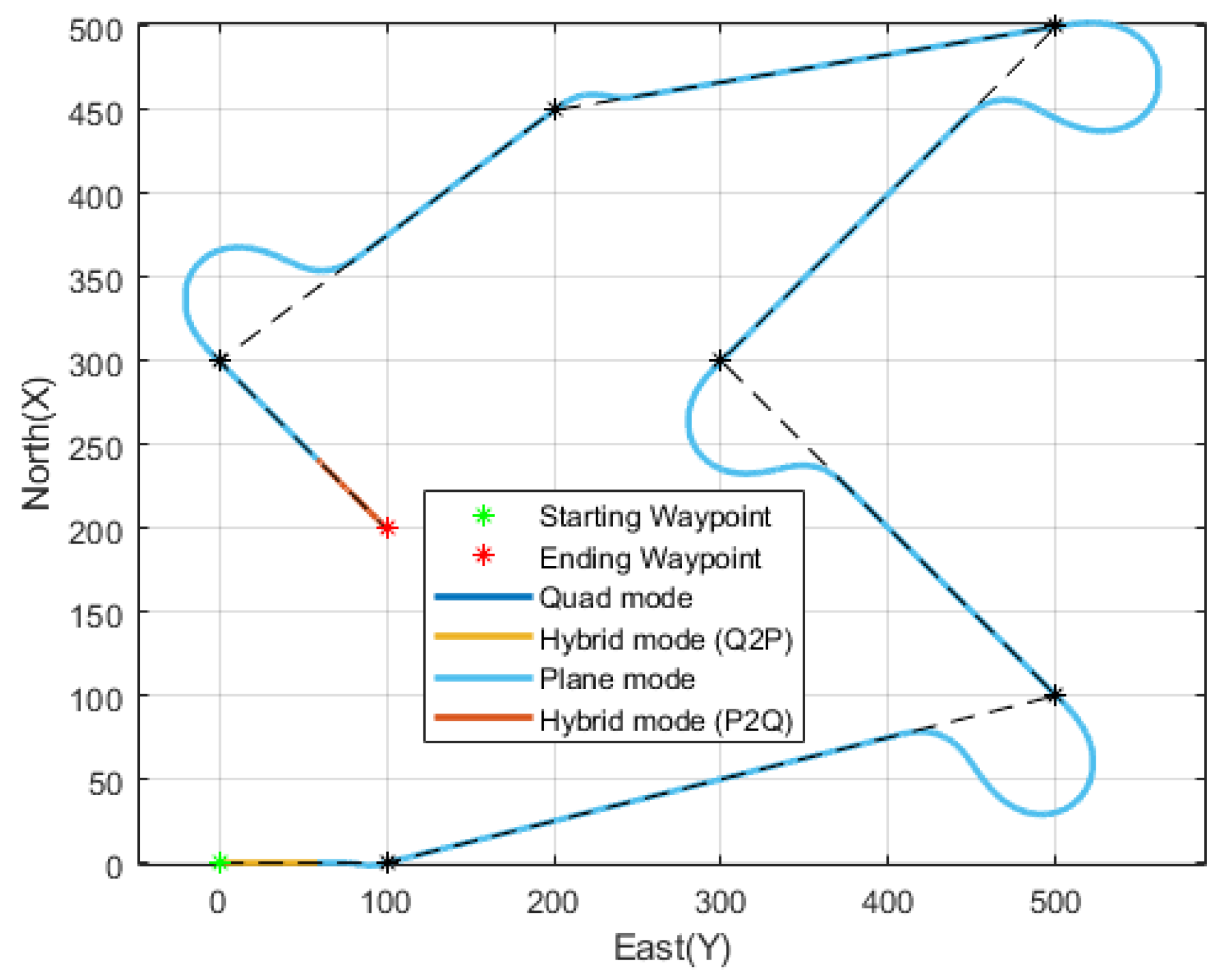
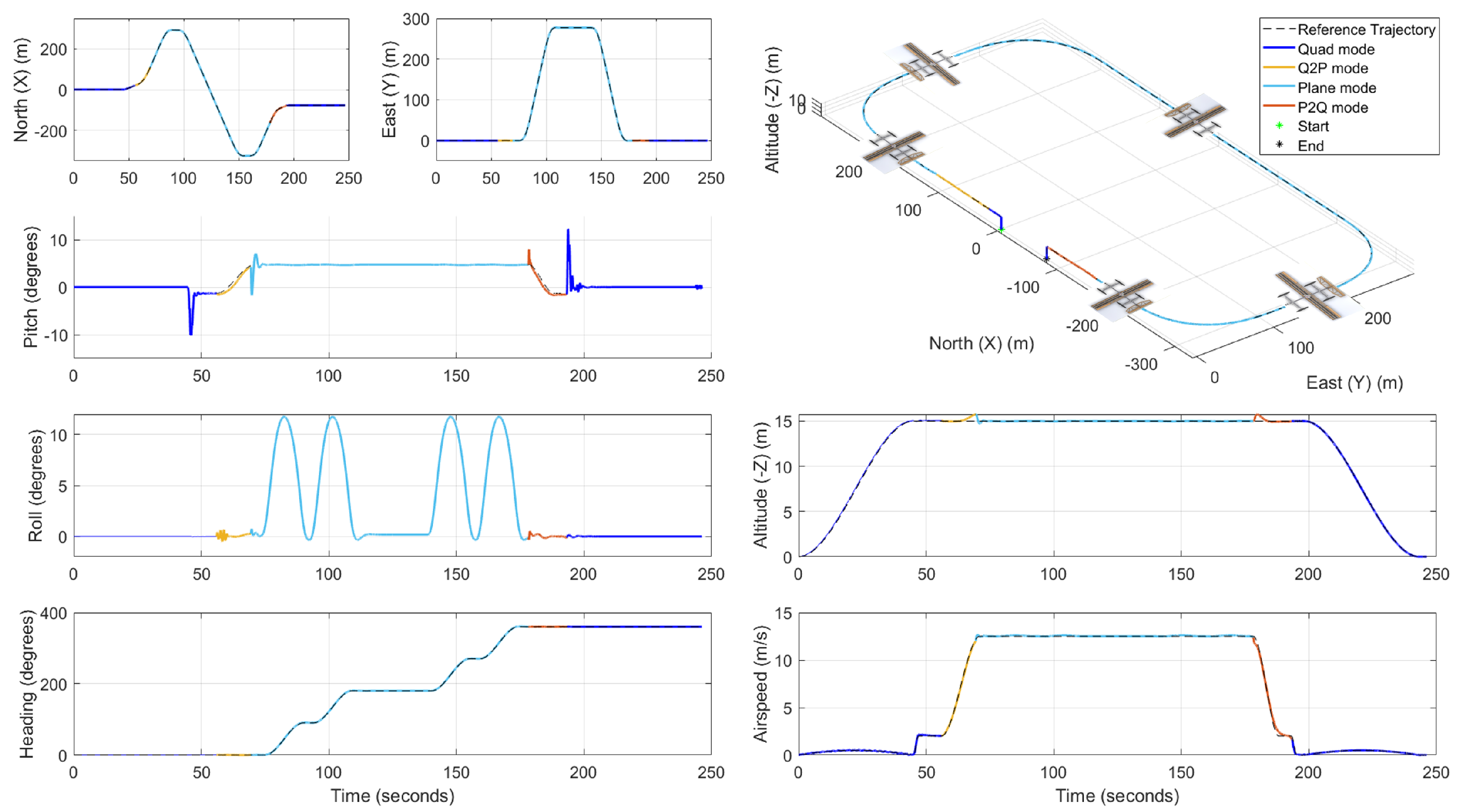
7.4. Transition Trajectories
QuadPlane Hybrid mode activates to assure stability when accelerating from Quad to Plane mode or vice versa. A
transition follows a cubic spline in airspeed from hover to the best cruise airspeed for the QuadPlane
= 12.5 m/s (as seen in
Section 8.1) over time
, subject to
= 2 m/s
2 with zero initial and final acceleration. Flight mode
M changes from Quad to Hybrid to Plane mode over the transition per Equation (
5), where
= 2 m/s and
= 12 m/s. Pitch angle time history
also follows a cubic spline from Quad trim pitch angle at hover to the Plane trim pitch angle at
= 12.5 m/s over the same transition time
, with zero initial and final pitch rate. After a
transition, the remaining segment is flown in Plane mode at the best cruise airspeed
= 12.5 m/s. The reverse happens over a
transition at a higher deceleration,
m/s
2, and a shorter time
.
transitions occur at the start of the segment, while
transitions occur towards the end of the segment to minimize total energy consumption by maximizing time spent in Plane mode.


