Article

A Novel Design of a Sliding Mode Controller Based on Modified ERL for Enhanced Quadcopter Trajectory Tracking

by
Ahmed Abduljabbar Mahmood
*,
Fernando García
and
Abdulla Al-Kaff
Department of Systems Engineering and Automation, University Carlos III of Madrid, 28911 Madrid, Spain
*
Author to whom correspondence should be addressed.
Drones 2025, 9(11), 737; https://doi.org/10.3390/drones9110737 (registering DOI)
Submission received: 13 September 2025 / Revised: 13 October 2025 / Accepted: 14 October 2025 / Published: 23 October 2025
(This article belongs to the Special Issue Path Planning, Trajectory Tracking and Guidance for UAVs: 3rd Edition)

Abstract

This paper introduces a new approach to obtain robust tracking performance, disturbance resistance, and input variation resistance, and eliminate chattering phenomena in the control signal and output responses of an unmanned aerial vehicle (UAV) quadcopter with parametric uncertainty. This method involves a modified exponential reaching law (ERL) of the sliding mode control (SMC) based on a Gaussian kernel function with a continuous nonlinear Smoother Signum Function (SSF). The smooth continuous signum function is proposed as a substitute for the signum function to prevent the chattering effect caused by the switching sliding surface. The closed-loop system’s stability is ensured according to Lyapunov’s stability theory. Optimal trajectory tracking is attained based on particle swarm optimization (PSO) to select the controller parameters. A comparative analysis with a classical hierarchical SMC based on different ERLs (sign function, saturation function, and SSF) is presented to further substantiate the superior performance of the proposed controller. The outcomes of the simulation prove that the suggested controller has much better effectiveness, unknown disturbance resistance, input variation resistance, and parametric uncertainty than the other controllers, which produce chattering and make the control signal range fall within unrealistic values. Furthermore, the suggested controller outperforms the classical SMC by reducing the tracking integral mean squared errors by 96.154% for roll, 98.535% for pitch, 44.81% for yaw, and 22.8% for altitude under normal flight conditions. It also reduces the tracking mean squared errors by 99.05% for roll, 99.26% for pitch, 40.18% for yaw, and 99.998% for altitude under trajectory tracking flight conditions in the presence of external disturbances. Therefore, the proposed controller can efficiently follow paths in the presence of parameter uncertainties, input variation, and external disturbances.

1. Introduction

Unmanned aerial vehicles (UAVs), especially small quadcopters, have advanced significantly in both military and civilian applications such as infrastructure management, the security sector, surveillance, and disaster assessment. With benefits including low cost, precise motions, and Vertical Take-Off and Landing (VTOL), these UAVs are being utilized increasingly for work in inaccessible areas. Unlike walking robots, UAVs are subjected to more substantial aerodynamic and gravitational forces, which significantly influence the dynamics of these airborne systems. Because of their complexity and six degrees of freedom (three for attitude and three for position), stability and control must be carefully considered. As a result, research on quadcopter UAVs has rapidly advanced, particularly in agriculture, logistics, and other domains that benefit from their mobility, simple mechanical design, and high maneuverability. However, achieving high-performance control remains difficult due to their dynamic complexities, model uncertainties, and external disturbances. Planar flying is necessary for quadcopter navigation in a number of application fields in order to track a moving object or follow a predetermined course under unpredictable circumstances. Various control algorithms have been proposed in existing research to enhance the tracking accuracy of quadcopter systems. One of the first academic works on the use of PID controllers in quadrotor systems was [1], which discussed gain tuning in PID control for quadrotors. A useful overview of quadcopter PID control is provided in [2]. Fractional-order PID controller design has been introduced in [3], which fully controls the quadrotor’s position and attitude using a modified Black–Nichols technique. In [4], the researchers examined and contrasted the tracking performance of type-1 and type-2 fuzzy neural networks using elliptical membership functions for the quadcopter VTOL aircraft trajectory tracking problem. As compared to a single PD controller, the experimental result demonstrates that the type-1 and type-2 fuzzy neural networks operating in tandem with a PD controller have noticeably lower steady-state errors. The suggested type-2 fuzzy neural network additionally exhibits superior noise ejection capabilities by utilizing elliptic membership functions. A multiple-layer hierarchical structure has been designed in [5] to control the velocity of the UAV using a hybrid control strategy that combines SMC and Linear Quadratic Regulator (LQR) techniques. To estimate the unmeasured states, a reduced-order observer is created and incorporated into the compensator. The controller achieved a short rising time and settling time, and slight overshoot. Other researchers implemented two adaptive controllers on both integer-order and fractional-order quadcopter UAV systems [6]. The results indicate that applying SMC and fractional-order SMC to the fractional-order quadcopter system yields superior control performance, robustness, and accuracy compared to the traditional integer-order quadcopter system. On the other hand, the data model is used to develop the model-free adaptive SMC for quadcopter attitude in [7], which guarantees rapid attitude angle convergence. To correct the detected disturbance and keep it from conflicting with the feedback control position, a disturbance observer has been added to the position controller. In [8], the control of the quadrotor UAV is achieved by using an enhanced integral backstepping SMC technique. This approach first adds the integral term to the virtual variable to improve the system’s performance; then the system is further treated to enhance its control performance in conjunction with SMC. A quadrotor UAV’s position and attitude tracking control in the presence of external disturbances and parametric uncertainties is proposed in [9] by combining sliding mode control with a neural network adaptive scheme using a novel approach. The suggested approach maintains the benefits of both approaches. Additionally, the path-following problem could be resolved in [10] using a hierarchical system that consists of a nonlinear H-infinity controller to stabilize the rotating movements and a model predictive controller to follow the trajectory reference. SMCs have many benefits, including robustness, adaptability, insensitivity to external disturbances, and fast responses; however, they also have drawbacks, such as chattering effects and high consumption of energy [11]. As a result, some authors have attempted to minimize chattering by replacing the typical SMC’s signum function with a continuous function, as seen in [12]. Next, an integral reinforcement learning approach is suggested, based on an optimal adaptive saturation function tuning approach. Also, the authors of [13,14] created the fast dynamic terminal SMC for attitude tracking control and tracking the position of a quadcopter. It can also achieve high-precision performance and minimize chattering produced by the switching control action. In [15], the scalar sign function technique is used in SMC and applied to an aluminum beam using a piezoceramic sensor and vibration control actuator. Furthermore, an excellent overview of various control strategies to address and fix a number of issues pertaining to autonomous quadcopters can be found in [16,17]. This work presents a novel Modified Sliding Mode Controller (MSMC) design that modifies the exponential reaching law of SMC using a kernel Gaussian formula and replaces the signum function with a continuous nonlinear function to eliminate the chattering effect and minimize the cost function. The proposed controller is applied to an underactuated, nonlinear quadcopter with Multiple-Input Multiple-Output (MIMO) dynamics for position and attitude tracking control considering different trajectories and external disturbances. Optimal trajectory tracking is achieved by online tuning of the controller parameters using the particle swarm optimization (PSO) algorithm. Four controllers are compared to evaluate the system’s performance. Simulation results show that both SMC based on the SSF and MSMC outperform the classical SMC in terms of robustness and performance, with MSMC achieving superior output performance compared to SMC based on the SSF. The novel contributions are hence summarized as follows:
1.
A new optimal adaptive sliding mode controller based on modification of ERL for an underactuated quadcopter system is developed that is employed under various simulation experiments like a trajectory tracking mission, automated take-off and landing, and altitude and attitude control in nominal mode, input variation mode, parametric uncertainty mode, and unknown disturbances mode.
2.
Elimination of the chattering effect caused by the switching sliding surface is conducted by employing a smooth continuous signum function as a substitute for the signum function. Then, the chattering effect is eliminated with the proposed SMC compared to that observed with classical SMC.
3.
All factors influencing the quadcopter’s dynamics, including gyroscopic effects, drag forces along the (x, y, z) axes, frictions from aerodynamic torque, and high-level non-holonomic limitations, were considered when designing the controller.
4.
Stability of the quadrotor’s trajectory tracking and attitude control system is demonstrated using Lyapunov’s theory.
5.
Our results demonstrate that the modified ERL improves the robustness of the SMC system when compared to previous research [11,13,14,18], and MATLAB R2021a simulations validate the theoretical framework and the suggested controller’s efficacy, robustness, and exact convergence.
This paper is structured as follows: The quadcopter UAV’s mathematical model is shown in Section 2. The problem statement is covered in Section 3. The controller architecture utilizing traditional SMC and an enhanced version of SMC is created in Section 4. In Section 5, the particle swarm optimization (PSO) technique is described, and a performance index is introduced. The simulation results and a comparative analysis are shown in Section 6. Finally, Section 7 provides the conclusions.

2. Nonlinear Quadcopter Dynamic Modeling

The underactuated quadrotor UAV, depicted in Figure 1, consists of four fixed-pitch rotors mounted symmetrically on a rigid cross-platform, with control electronics positioned at the center. The diametrically opposed rotors rotate in the same direction, and the vehicle’s movement is controlled by adjusting their rotational speeds. By strategically varying these speeds, the quadrotor can execute ascent and descent maneuvers, as well as rotational movements such as rolling (by an angle ϕ ), pitching (by an angle θ ), and yawing (by an angle ψ ). Each rotor generates a torque about its centre of rotation, and when all rotors spin at an equal angular velocity, the net aerodynamic torque acting on the quadrotor is zero. This occurs because the torques produced by the counter-rotating rotor pairs effectively cancel each other out. In order to produce yaw motion, one pair of rotors’ rotational speed is increased while the other pair’s speed is decreased. This causes an imbalance in the aerodynamic torque about the yaw axis. Each rotor generates an upward push perpendicular to the plane of blade rotation in addition to torque. The two pairs of rotors that revolve in the same direction use differential propulsion to control roll and pitch motions. The quadcopter rotates around the pitch or roll axis by increasing the speed of one of its two rotors while reducing the speed of the other [5,18].
As seen in Figure 1, let I = ( I x , I y , I z ) represents an inertial frame, and B = ( X B , Y B , Z B ) represents a frame that is firmly fixed to the quadrotor. This work makes the following assumptions in order to construct the quadcopter dynamic model and derive the subsequent control law:
1.
The quadcopter has a symmetrical architecture with a rigid body and rigid propellers.
2.
The body-fixed frame origin is precisely the quadcopter’s center of mass.
3.
Drag and thrust forces are proportionate to the rotor speed squared.
Given these assumptions, the dynamics of the fuselage can be described as those of a rigid body in space, with the additional aerodynamic forces resulting from the rotation of the rotors. Through use of the Newton–Euler formalism, the dynamic equations are expressed as follows [19]:
ξ ˙ = v m ξ ¨ = f f + f t + f g R ˙ = R S ( Ω ) J Ω ˙ = Ω J Ω + Γ f Γ a Γ g
where ξ is the position of the quadcopter’s center of mass in the inertial frame, v is the linear velocity, m is the total mass, and J R 3 × 3 is the symmetric positive definite inertia matrix of the quadcopter in the body frame with respect to B:
J = I x 0 0 0 I y 0 0 0 I z
According to [20], R is the homogeneous rotation matrix and Ω is the angular velocity of the airframe. The rotation matrix R is defined as
R = c θ c ψ c ψ s ϕ s θ s ψ c ϕ c ψ c ϕ s θ + s ψ s ϕ c θ s ψ s ψ s ϕ s θ + c ψ c ϕ s ψ c ϕ s θ c ψ s ϕ s θ c θ s ϕ c θ c ϕ
where c and s denote the cosine and sine functions, respectively. The angular velocity vector Ω is given by
Ω = Ω 1 Ω 2 Ω 3 = 1 0 s θ 0 c ϕ s ϕ c θ 0 s ϕ c ϕ c θ ϕ ˙ θ ˙ ψ ˙
The skew-symmetric matrix S ( Ω ) is defined as
S ( Ω ) = 0 Ω 3 Ω 2 Ω 3 0 Ω 1 Ω 2 Ω 1 0
The total thrust force f f generated by the four rotors is given by
f f = R · 0 0 i = 1 4 F i , where F i b ω i 2
Here, b is the lift coefficient and ω i is the angular speed of rotor i. The drag force f t along the body axes ( X B , Y B , Z B ) is given by
f t = K f t x 0 0 0 K f t y 0 0 0 K f t z ξ ˙
where K f t x , K f t y , and K f t z are the translational drag coefficients. The gravitational force f g is
f g = 0 0 m g
The moment generated by the quadcopter relative to the body-fixed frame, Γ f , is given by
Γ f = l ( F 3 F 1 ) l ( F 4 F 2 ) d ( ω 1 2 ω 2 2 + ω 3 2 ω 4 2 )
where l is the distance between the propeller’s rotational axis and the quadcopter’s center of mass, and d is the drag coefficient. The aerodynamic friction torque Γ a is
Γ a = K f a x 0 0 0 K f a y 0 0 0 K f a z Ω 2
where K f a x , K f a y , and K f a z are aerodynamic friction coefficients. The gyroscopic torque Γ g is
Γ g = i = 1 4 Ω J r 0 0 ( 1 ) i + 1 ω i
where J r is the rotor inertia. The complete dynamic model of the quadcopter’s angular and translational motion is given by
ϕ ¨ = 1 I x l U 2 + ( I y I z ) ( ψ ˙ cos ϕ cos θ θ ˙ sin ϕ ) ( θ ˙ cos ϕ + ψ ˙ sin ϕ cos θ ) J r Ω r ( ψ ˙ sin ϕ cos θ + θ ˙ cos ϕ ) K f a x ( ϕ ˙ 2 2 ϕ ˙ ψ ˙ sin 2 θ )
θ ¨ = 1 I y l U 3 + ( I z I x ) ( ψ ˙ cos ϕ cos θ θ ˙ sin ϕ ) ( ϕ ˙ ψ ˙ sin θ ) J r Ω r ( ψ ˙ sin θ ϕ ˙ ) K f a y ( θ ˙ 2 cos 2 ϕ + 2 ϕ ˙ ψ ˙ sin ϕ cos ϕ cos θ + ψ ˙ 2 sin 2 ϕ cos 2 θ )
ψ ¨ = 1 I z U 4 + ( I x I y ) ( ψ ˙ sin ϕ cos θ + θ ˙ cos ϕ ) ( ϕ ˙ ψ ˙ sin θ ) K f a z ( θ ˙ 2 sin 2 ϕ 2 ϕ ˙ ψ ˙ sin ϕ cos ϕ cos θ + ψ ˙ 2 cos 2 ϕ cos 2 θ )
The translational accelerations are given by
x ¨ = 1 m ( cos ϕ sin θ cos ψ + sin ϕ sin ψ ) U 1 K f t x x ˙
y ¨ = 1 m ( cos ϕ sin ψ sin θ cos ψ sin ϕ ) U 1 K f t y y ˙
z ¨ = 1 m cos ϕ cos θ U 1 m g K f t z z ˙
To simplifying the dynamic equations of the quadcopter model (only used to simplify the formulation of the equations), small-angle approximations are used (i.e., cos x 1 , sin x 0 ). Under these conditions, Equations (12)–(17) simplify as shown in [19]:
ϕ ¨ = a 1 ψ ˙ θ ˙ + b 1 U 2 + c 1 Ω r θ ˙ + d 1 ϕ ˙ 2
θ ¨ = a 2 ϕ ˙ ψ ˙ + b 2 U 3 + c 2 Ω r ϕ ˙ + d 2 θ ˙ 2
ψ ¨ = a 3 ϕ ˙ θ ˙ + b 3 U 4 + c 3 ψ ˙ 2
The simplified translational dynamics of the quadcopter are expressed as
x ¨ = a 4 x ˙ + b 4 ( cos ϕ cos ψ sin θ + sin ϕ sin ψ ) U 1
y ¨ = a 5 y ˙ + b 5 ( cos ϕ sin ψ sin θ sin ϕ cos ψ ) U 1
z ¨ = a 6 z ˙ + b 6 ( cos ϕ cos θ ) U 1 g
The constants are defined as
a 1 = I y I z I x ,         b 1 = l I x ,         c 1 = J r I x ,         d 1 = K f a x I x a 2 = I z I x I y ,         b 2 = l I y ,         c 2 = J r I y ,         d 2 = K f a y I y a 3 = I x I y I z ,         b 3 = 1 I z ,         c 3 = K f a z I z a 4 = K f t x m ,         b 4 = 1 m a 5 = K f t y m ,         b 5 = 1 m a 6 = K f t z m ,         b 6 = 1 m Ω r = ω 1 ω 2 + ω 3 ω 4
From Equations (18)–(23), it is evident that the quadcopter is a nonlinear underactuated system that has six outputs ( ϕ , θ , ψ , x , y , z ) with four control inputs (U1, U2, U3, U4) described by
U 1 = b ( ω 1 2 + ω 2 2 + ω 3 2 + ω 4 2 ) U 2 = b ( ω 4 2 ω 2 2 ) U 3 = b ( ω 3 2 ω 1 2 ) U 4 = d ( ω 1 2 ω 2 2 + ω 3 2 ω 4 2 )
The control signals U 2 , U 3 , and U 4 correspond to the roll ( ϕ ) , pitch ( θ ) , and yaw ( ψ ) angles, respectively. The position states x, y, and z are influenced by ϕ , θ , and U 1 . To independently control the output positions, three virtual control inputs ( U x , U y , U z ) are introduced:
U x = cos ϕ sin θ cos ψ + sin ϕ sin ψ U y = cos ϕ sin θ sin ψ sin ϕ cos ψ U z = U 1
The desired roll and pitch angles are derived from the virtual controls:
ϕ d = arcsin U x sin ψ d U y cos ψ d U x 2 + U y 2 + U z 2 θ d = arctan U x cos ψ d + U y sin ψ d U z

3. Problem Statement

The state-space form of the quadcopter dynamic equations created in this paper can be rewritten as the following continuous-time system:
X ¨ ( t ) = f ( X , t ) + g ( X ) · U i ( t ) + d i ( t )
where d i = [ d 1 , d 2 , d 3 , d 4 , d 5 , d 6 ] T represents the unknown external disturbances and some dynamics of the system (Equations (18)–(23)), | d i |   δ i (upper bound), i = 1 , , 6 represents the state-space number, U i = [ U 2 , U 3 , U 4 , U x , U y , U 1 ] T represents the control signals, and X = [ X 1 , X 2 , , X 6 ] T represents the state vector of the quadcopter system, such that
X i = [ ϕ , θ , ψ , x , y , z ] T
The nonlinear functions f ( X ) and g ( X ) , describing the system dynamics and control, respectively, are expressed as the following matrices:
f ( X ) = f 1 f 2 f 3 f 4 f 5 f 6 = a 1 ψ ˙ θ ˙ a 2 ϕ ˙ ψ ˙ a 3 θ ˙ ϕ ˙ 0 0 g
g ( X ) = b 1 0 0 0 0 0 0 b 2 0 0 0 0 0 0 b 3 0 0 0 0 0 0 b 4 0 0 0 0 0 0 b 5 0 0 0 0 0 0 b 6

4. Control Design

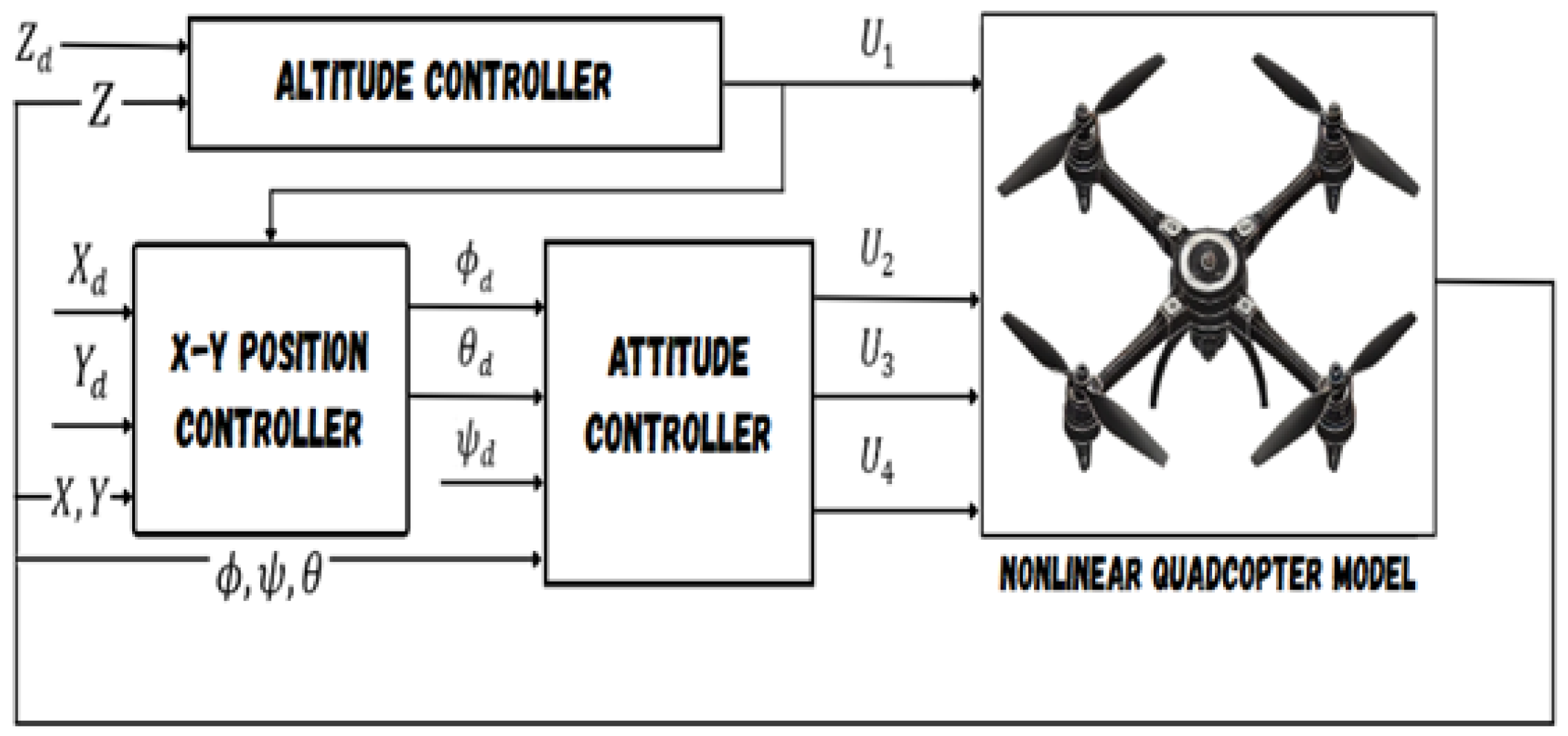
The quadcopter-controlled system block diagram is displayed in Figure 2, where the first part refers to position and yaw angle control. The desired position ( x d , y d , z d ) and desired yaw angle ψ d are predefined by the user. Based on these inputs, the simulation program automatically calculates the required roll and pitch signals using sensor data to ensure the quadrotor remains stable during flight. Subsequently, the second part refers to attitude control. The main goal of the control system is to guide a trajectory state X in the direction of a desired reference trajectory: X d i = X d 1 X d 2 X d 3 X d 4 X d 5 X d 6 T = ϕ d θ d ψ d x d y d z d T . The SMC design process consists of two parts. Designing a sliding surface is the initial stage in order to achieve the necessary system response for the plant that is confined to it. This indicates that a different set of equations, defining what is known as the switching surface, must be satisfied by the state variables of the plant dynamics. Building the switched feedback gains required to move the plant’s state trajectory toward the sliding surface is the second phase. These designs are based on the generalized Lyapunov stability theory.

4.1. Classical SMC Design Based on ERL

The initial step of constructing the SMC for the quadcopter UAV system involves defining the sliding surface as follows:
S i ( t ) = e ˙ i ( t ) + λ i e i ( t )
where e i ( t ) = X i ( t ) X d i ( t ) represents the tracking error, e ˙ i ( t ) = X ˙ i ( t ) X ˙ d i ( t ) represents the derivative tracking error, and λ i is the sliding surface coefficient that must be positive and selected carefully to satisfy the Hurwitz condition. The time derivative of Equation (32) can be determined as follows:
S ˙ i ( t ) = e ¨ i ( t ) + λ i e ˙ i ( t )
By substituting Equation (28) into Equation (33), the time derivative of the sliding surface can be rewritten as
S ˙ i ( t ) = f i ( X , t ) + b i U i ( t ) + d i ( t ) X ¨ d i ( t ) + λ i e ˙ i ( t )
When the state reaches the sliding manifold and approaches equilibrium, the expected motion constraints are shown by the sliding mode manifold S i . The controller will ensure that the trajectories of X i do not escape from the sliding surface in the ideal scenario, i.e., that the state values remain on the manifold S i = 0 and are driven to the sliding surface in finite time. This can be achieved by using various types of reaching control law techniques, such as conventional ERL [21], which can be expressed as follows:
S ˙ i ( t ) = k i sign ( S i ( t ) ) λ i S i ( t ) + d i ( t ) , k i > 0 , λ i > 0
The approach rate is represented by the coefficient k i , and the signum function (Si) is defined as
sign ( S i ) = 1 if S i < 0 0 if S i = 0 1 if S i > 0
The equivalent sliding control law can be obtained by solving Equations (34) and (35) as follows:
U i ( t ) = 1 b i X ¨ d i ( t ) f i ( t ) k i sign ( S i ( t ) ) 2 λ i e ˙ i ( t ) λ i 2 e i ( t )
The Lyapunov stability theory was applied to ensure the system’s stability; hence, the Lyapunov candidate was chosen as
V i ( S i ) = 1 2 S i 2
By applying Equation (34) to the derivative of the Lyapunov candidate, we obtain
V ˙ i ( S i ) = S i S ˙ i = S i f i ( t ) + b i U i ( t ) + d i ( t ) X ¨ d i ( t ) + λ i e ˙ i ( t )
Also, Equation (37) can be substituted into Equation (39) to obtain
V ˙ i ( S i ) = λ i S i 2 k i S i sign ( S i ) + S i d i ( t ) = λ i S i 2 k i | S i | + S i d i ( t )
Remark 1.
The quadcopter UAV’s trajectory tracking is guaranteed to be stable under SMC based on the signum function if the controller design parameters are selected such that k i δ i S i 0 . This condition ensures that the Lyapunov candidate is positive definite and its derivative V ˙ i 0 is negative definite or semi-negative definite, leading the sliding surfaces to converge to zero as t →∞.

4.2. SMC Design Based on ERL Using Saturation Function

Some studies have attempted to use the saturation function for the SMC’s switching surfaces, such as [22], for the precision positioning of a nano-positioning stage. Other researchers have used the hyperbolic tangent function [23] for the switched reluctance motor. To improve sliding mode controller performance, the discontinuous sign function is replaced by a saturation function to reduce chattering. The saturation function utilized in the control law is defined as
sat ( S i ) = sign ( S i ) if | S i | > μ S i μ if | S i | μ
Switch control is applied outside the boundary layer ( μ ), while linear feedback control is used within it. In this case, the control signal of the SMC can be stated as follows:
U i ( t ) = 1 b i X ¨ d i ( t ) f i ( t ) k i sat ( S i ( t ) ) 2 λ i e ˙ i ( t ) λ i 2 e i ( t )
Through use of the same Lyapunov candidate and the same procedure utilized previously, quadcopter stability can be achieved using the following equation:
V ˙ i ( S i ) = λ i S i 2 k i S i sat ( S i ) + S i d i ( t ) = λ i S i 2 k i | S i | sat ( | S i | ) + S i d i ( t )
Remark 2.
The quadcopter stability is guaranteed under SMC based on the saturation function, if the controller design parameters are selected such that sat ( | S i | ) δ i / k i , S i , and this ensures that V ˙ i 0 always. The ultimate bound will be | S i | ( μ / k i ) δ i . The saturation function used was able to stabilize the system as t → ∞, and the upper and lower bounds were selected based on heuristic experience. However, the system is still struggling to decrease sliding chattering and increase approaching speed. In the next subsection, we will propose a solution to overcome these difficulties.

4.3. Adaptive SMC Design Based on Modified ERL

The classical ERL offers good convergence, but the system experiences significant chattering when approaching the sliding mode. To prevent the chattering effect caused by the switching sliding surface, a smooth continuous nonlinear function is proposed and can be used to approximate the discontinuous switching function. Therefore, the signum function sign ( S i ) in the traditional ERL is replaced by a nonlinear switching surface function (SSF) in the new reaching law, which can be expressed by the following equation:
SSF ( S i ) = S i S i 2 + e 1 / ε
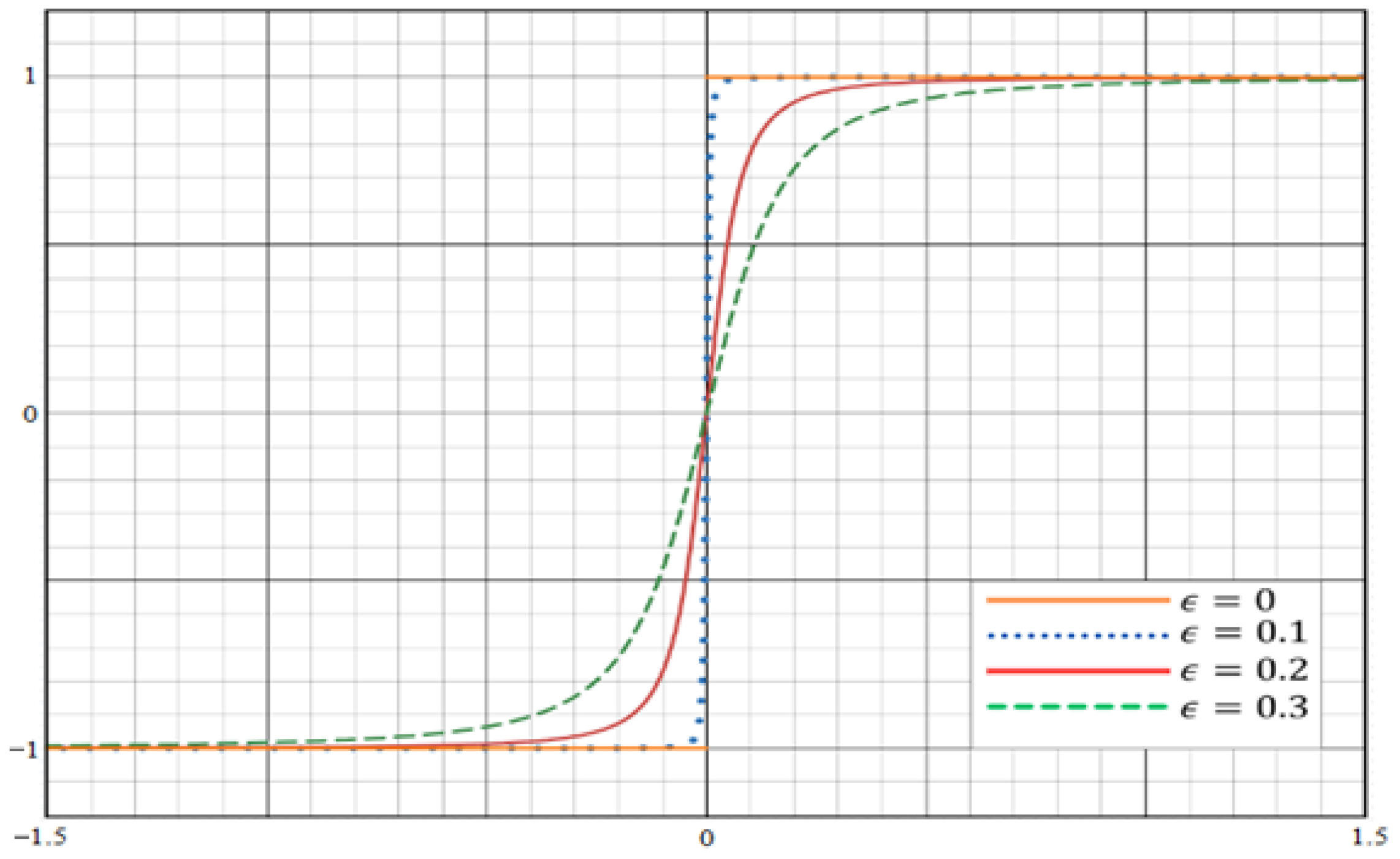
where ε is a positive tuning value between 0 and 1 for smoothing the discontinuity. It is manually calibrated to reduce chattering noise. The varied SSFs based on different values of ε are presented in Figure 3. On the other hand, the approaching speed to the sliding surface and system performance can be improved by modifying the traditional ERL based on the Gaussian kernel function (GK). Consequently, the modified ERL will be created as follows:
S ˙ i ( t ) = k i GK ( S i ) · S i S i 2 + e 1 / ε λ i S i ( t )
Presume that GK ( S i ) = A · e 1 2 S i 2 , where A = ( 2 π ) D / 2 and D is the space dimension. To stabilize and converge to the sliding surface within a specified time, the condition V ˙ i 0 must be met. In this case, substituting Equation (45) into the derivative of the Lyapunov candidate (Equation (38)), we get
V ˙ i ( S i ) = λ i S i 2 k i GK ( S i ) · S i 2 S i 2 + e 1 / ε + S i d i ( t )
Remark 3.
The quadcopter stability is guaranteed under adaptive SMC based on the modified ERL if the controller design parameters are selected such that | S i | δ i / k i , S i and the GK ( S i ) remains strictly positive for all values of S i . Therefore, these conditions ensure that V ˙ i 0 and the sliding surface converges to zero as t → ∞. The overall control law of the adaptive SMC based on the modified ERL can be expressed as follows:
U i ( t ) = 1 b i X ¨ d i ( t ) f i ( t ) k i GK ( S i ) · S i 2 S i 2 + e 1 / ε 2 λ i e ˙ i ( t ) λ i 2 e i ( t )

5. Optimal SMC and Performance Indices

5.1. Basics of Particle Swarm Optimization

In 1995, Eberhart and Kennedy first proposed particle swarm optimization (PSO), a stochastic optimization method [24,25]. The PSO algorithm mimics the social behavior of various animals, such as fish, birds, insects, and herds. These swarms work together to find food, and each member continuously modifies the search strategy based on its own and other members’ learning experiences. The PSO can be expressed mathematically by applying a swarm size of N and the position vector of each particle in a space of dimension d as x i = ( x i 1 , x i 2 , , x i d ) . While the velocity vector is represented by V i = ( V i 1 , V i 2 , , V i d ) , the optimal position of an individual is represented by P i = ( P i 1 , P i 2 , , P i d ) , and the optimal swarm position is represented by P g = ( P g 1 , P g 2 , , P g d ) , which corresponds to the position with the lowest fitness value. Each particle represents a candidate solution within the search space and updates its position over each iteration guided by changes in its velocity. Initially, particle locations and velocities are initialized randomly. Then, each particle attempts to enhance its fitness by maintaining momentum in the direction of its current velocity and is attracted toward its own best-known position P i d ( t + 1 ) . The update formula for the individual’s optimal position in the original PSO method is as follows [26]:
P i d ( t + 1 ) = x i d ( t + 1 ) if f ( x i ( t + 1 ) ) < f ( P i ( t ) ) P i d ( t ) otherwise
Finally, the particle’s position is updated for the next iteration based on its newly computed velocity. Therefore, the optimum position of the swarm is equal to the optimal positions of each individual. The following equations represent the updated velocity and position formulas, respectively:
V i d ( t + 1 ) = V i d ( t ) + c 1 · rand · ( P i d ( t ) x i d ( t ) ) + c 2 · rand · ( P g d ( t ) x i d ( t ) )
x i d ( t + 1 ) = x i d ( t ) + V i d ( t + 1 )
Here, c 1 and c 2 represent the acceleration coefficients, and the uniformly distributed random number rand [ 0 , 1 ] adds stochastic behavior. Shortly after the original PSO technique was proposed, a modified version of the algorithm [27] was developed since the original version was not very effective in solving optimization problems. After adding an inertia weight w to the velocity update calculation, the resulting formula becomes
V i d ( t + 1 ) = w · V i d ( t ) + c 1 · rand · ( P i d ( t ) x i d ( t ) ) + c 2 · rand · ( P g d ( t ) x i d ( t ) )

5.2. Optimal SMC Based on PSO

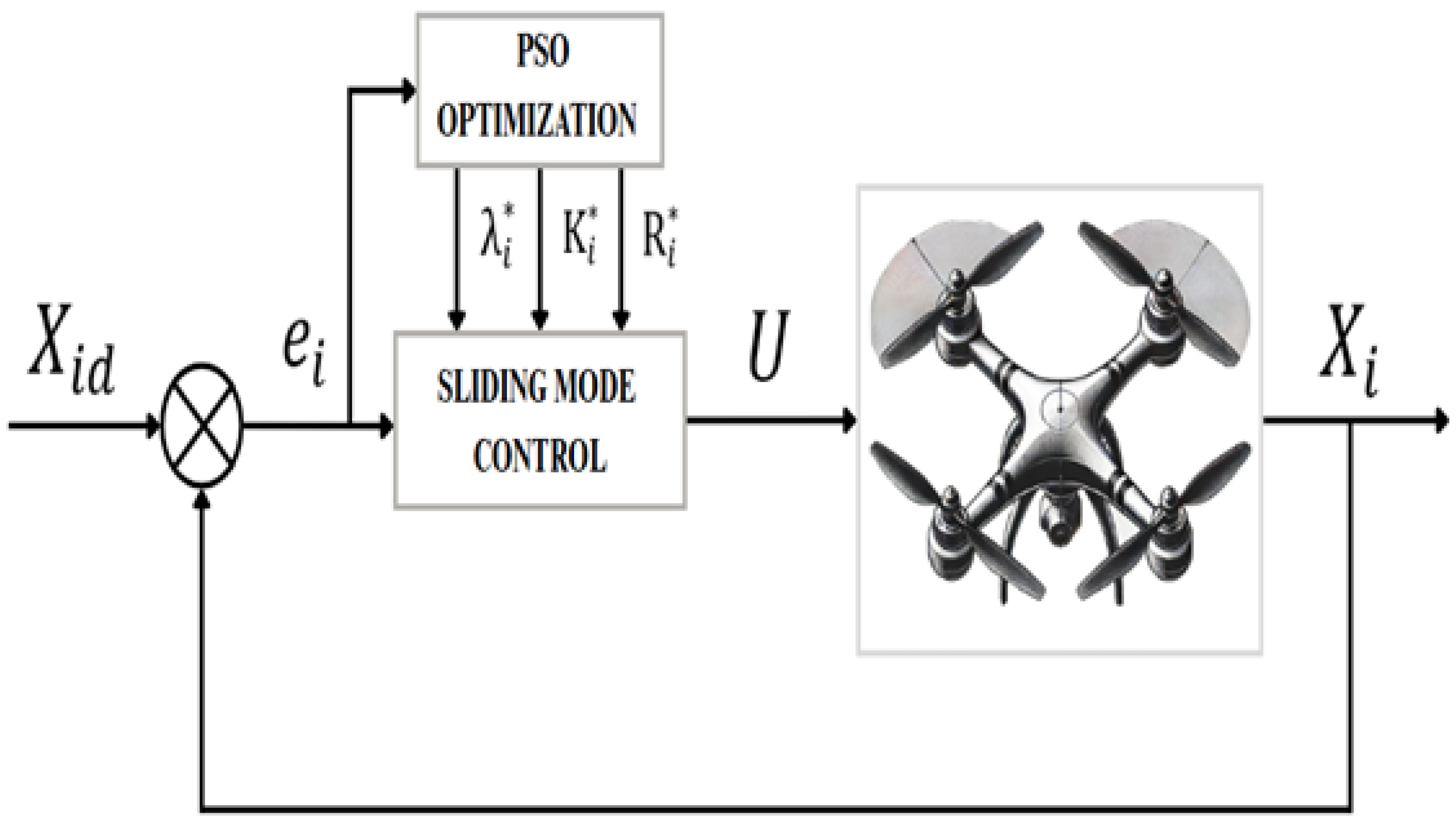
The optimal SMC parameters for the outputs of the quadcopter system ( ϕ , θ , ψ , x , y , z ) can be obtained online using the PSO algorithm technique. The optimal estimations of λ i and k i guarantee the optimal tracking control performance under both normal flight conditions and flight conditions affected by external disturbances. The optimal SMC parameters for the six controllers in the first and second scenarios, where Equations (37) and (42) were utilized as control signals, are given by ( λ 1 * , λ 2 * , λ 3 * , λ 4 * , λ 5 * , λ 6 * , k 1 * , k 2 * , k 3 * , k 4 * , k 5 * , k 6 * ). In the third scenario, where Equation (47) was used as a control signal, the optimal adaptive SMC parameters are ( λ 1 * , λ 2 * , λ 3 * , λ 4 * , λ 5 * , λ 6 * , k 1 * , k 2 * , k 3 * , k 4 * , k 5 * , k 6 * , R 1 * , R 2 * , R 3 * , R 4 * , R 5 * , R 6 * ), where k i * = A · k ˜ i and R i * is an optimal positive Gaussian kernel constant. Figure 4 shows the block diagram of the optimal proposed SMC based on the modified ERL. The optimal control signal can be rewritten as
U i ( t ) = 1 b i X ¨ d i ( t ) f i ( t ) k i * · S i 2 · e R i * S i 2 · 1 S i 2 + e 1 / ε 2 λ i * e ˙ i ( t ) ( λ i * ) 2 e i ( t )
The PSO algorithm uses 200 particles within a search space from 0 to 500. It operates in 12 dimensions for the first and second scenarios, and 18 dimensions for the third. A weight factor of w = 0.8 is applied to balance local exploitation and global exploration. The acceleration coefficients are set to C1 = 0.8 and C2 = 1.2 to prevent premature convergence. The algorithm stops after a maximum of 50 iterations, which acts as the stopping criterion. Additionally, the particle with the highest fitness value is kept throughout the process.

5.3. Performance Indices

The performance of the quadcopter’s responses with the proposed SMC controllers is evaluated using cost functions (CF1), which include mean squared error (MSE) or integral mean squared error (IMSE), settling time ( t s ), and maximum peak overshoot ( M p ). The following cost function is applied during hovering and trajectory tracking without external disturbances:
C F 1 = 10 · I M S E 1 + 10 · I M S E 2 + I M S E 3 + I M S E 4 + 0.5 M p x + 0.3 t s x + I M S E 5 + 0.5 M p y + 0.3 t s y + I M S E 6 + 0.5 M p z + 0.3 t s z
where ISE i = 0 t e i ( t ) 2 d t = [ ISE 1 , ISE 2 , ISE 3 , ISE 4 , ISE 5 , ISE 6 ] , corresponding to roll, pitch, yaw, longitude, latitude, and altitude, respectively. Also, the cost function that is used in the presence of external disturbances is expressed as follows:
CF 2 = i = 1 6 MSE i
where MSE i = mean ( e i 2 ) = [ MSE 1 , MSE 2 , MSE 3 , MSE 4 , MSE 5 , MSE 6 ] , corresponding to roll, pitch, yaw, longitude, latitude, and altitude, respectively.

6. Simulation and Results

The simulation of the controlled quadcopter system is executed for 20 s with a sampling time equal to 0.001 to calculate the fitness function and to prove the capability of our controller design to stabilize the quadcopter in less time and eliminate the chattering in both control signal and output responses under quadrotor hovering at a fixed spot, and under hovering and landing during tracking missions. The symbols and values of the parameters utilized in the quadcopter UAV’s dynamic model are summarized in Table 1. The nonlinear quadcopter dynamic system is implemented in MATLAB/Simulink with SMC based on classical ERL, SMC based on the saturation function in ERL (S-SMC), SMC based on the SSF in ERL (SSF-SMC), and SMC based on modified ERL (MSMC) controllers. Table 2 presents the optimal parameter values for the quadcopter across the various controllers discussed above.

6.1. Hovering Flight Under Attitude Stabilization

The main goal of the proposed control system is to guide a trajectory state (X) in the direction of a desired reference trajectory. The initial trajectory state of the quadcopter system is assumed to be zero, while the desired reference trajectory state vector is considered to be
X d = [ ϕ d , θ d , ψ d , x d , y d , z d ] T = [ ϕ d , θ d , 5 , 1 m , 2 m , 2 m ] T
and ε in the SSF has been specified as 0.1 to obtain better smoothness. It is worth noting that the desired roll and pitch angles are not fixed but are dynamically derived from the control efforts of the x-axis and y-axis controllers, denoted by U x and U y , respectively. As a result, the values of ϕ d and θ d are directly influenced by the outputs of these controllers.
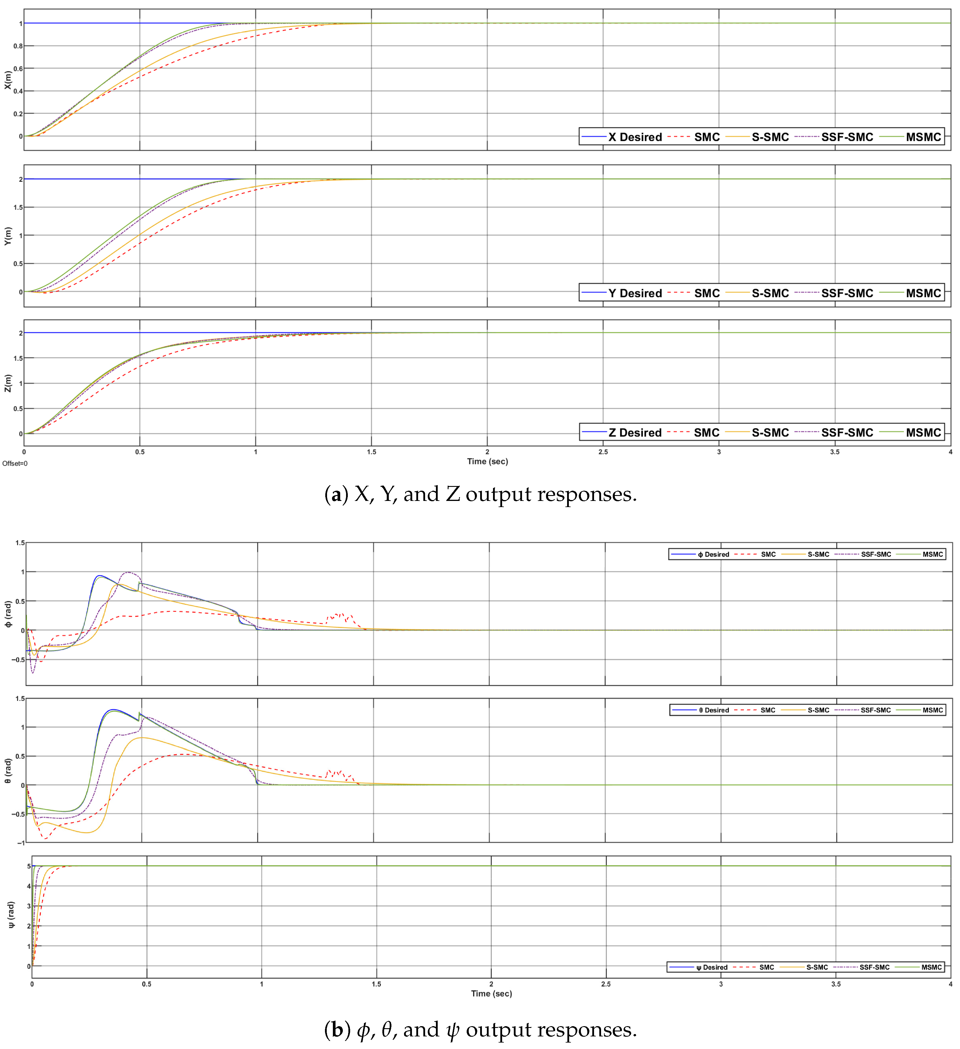
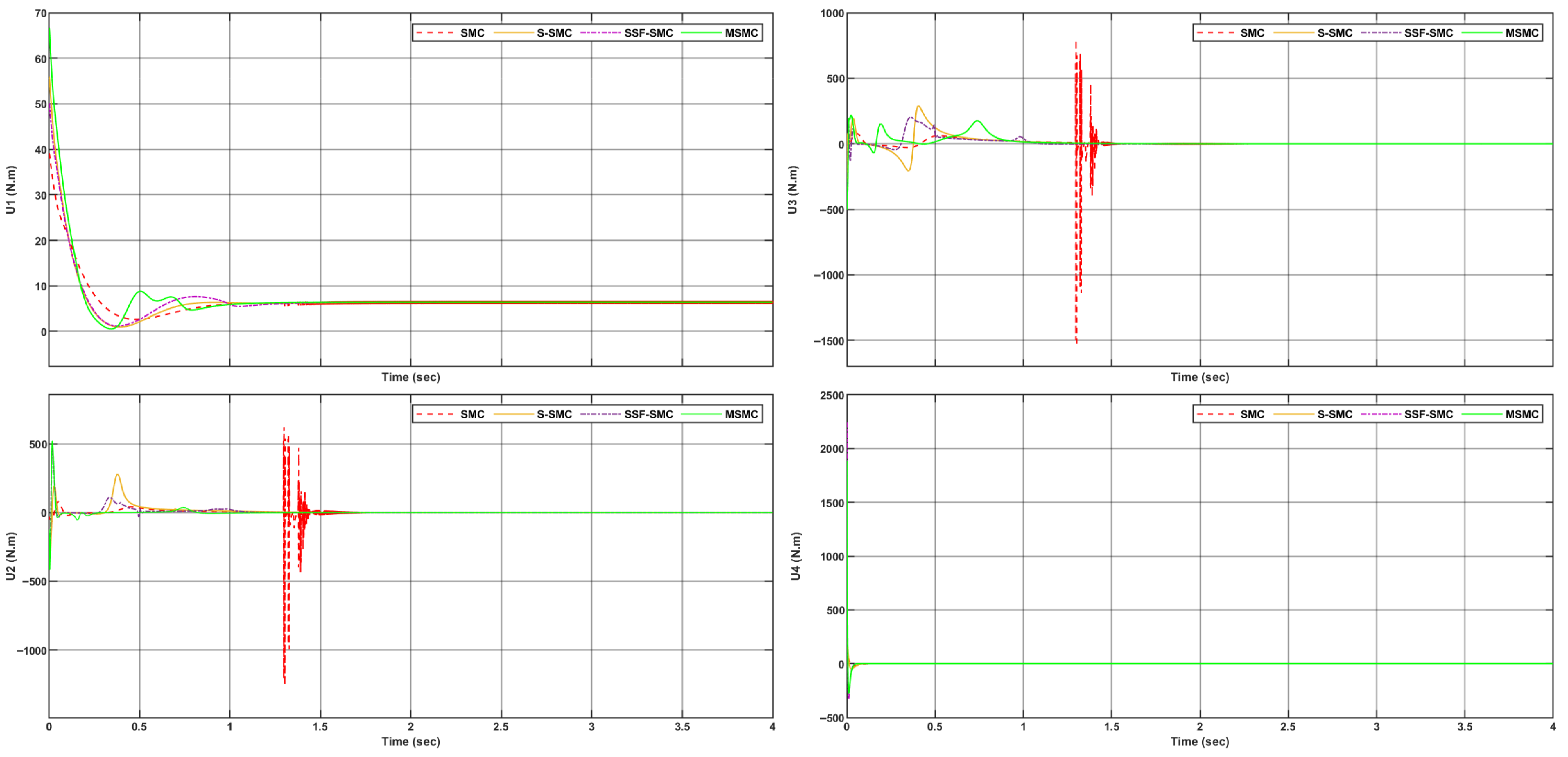
For this scenario, the optimal parameter values for quadcopter controllers are presented in Table 2. The system output responses for the six state variables are shown in Figure 5, while the corresponding control inputs are illustrated in Figure 6. The output responses demonstrate that the proposed controller, incorporating the SSF approach, achieves superior performance. Specifically, it exhibits faster convergence to the desired states with minimal steady-state error and reduced overshoot and chattering compared to alternative methods.
The Performance Improvement ( P I ) between the controllers can be quantified as follows:
P I = 1 C F Controller A C F Controller B × 100 %
The improvement in the proposed controller’s performance relative to the classical SMC can be evaluated using the following:
P I = 1 2.9630 5.2544 × 100 % = 43.6092 % .
Comparison of the proposed controller’s performance with the S-SMC can be evaluated using the following:
P I = 1 2.9630 4.1762 × 100 % = 29.015 % .
Meanwhile, the improvement in the proposed controller’s performance relative to the proposed SSF-SMC can be evaluated using the following:
P I = 1 2.9630 3.4748 × 100 % = 14.729 % .
Furthermore, the suggested controller outperforms classical SMC by decreasing tracking errors under hovering flight conditions to 96.154% for roll, 98.535% for pitch, 44.81% for yaw, and 22.8% for altitude.

6.2. Trajectory Tracking Flight in the Presence and Absence of Disturbances

The objective of this scenario is to guide the quadrotor in tracking a desired circular trajectory while maintaining a stable hover, ensuring attitude stabilization, and executing a landing maneuver accompanied by a 5° yaw rotation. In this scenario, the value of ε is considered to be 0.2 to test the role of this parameter in improving the smoothness of the SSF. Therefore, the quadcopter was required to track the desired trajectory defined for t 0 :
[ x d , y d ] = 1 + sin 2 π t 10 , 2 + 2 sin 2 π t 10 π 2
z d = 0.625 t for 0 t < 4 2.5 for 4 t 16 0.625 t for 16 < t < 20
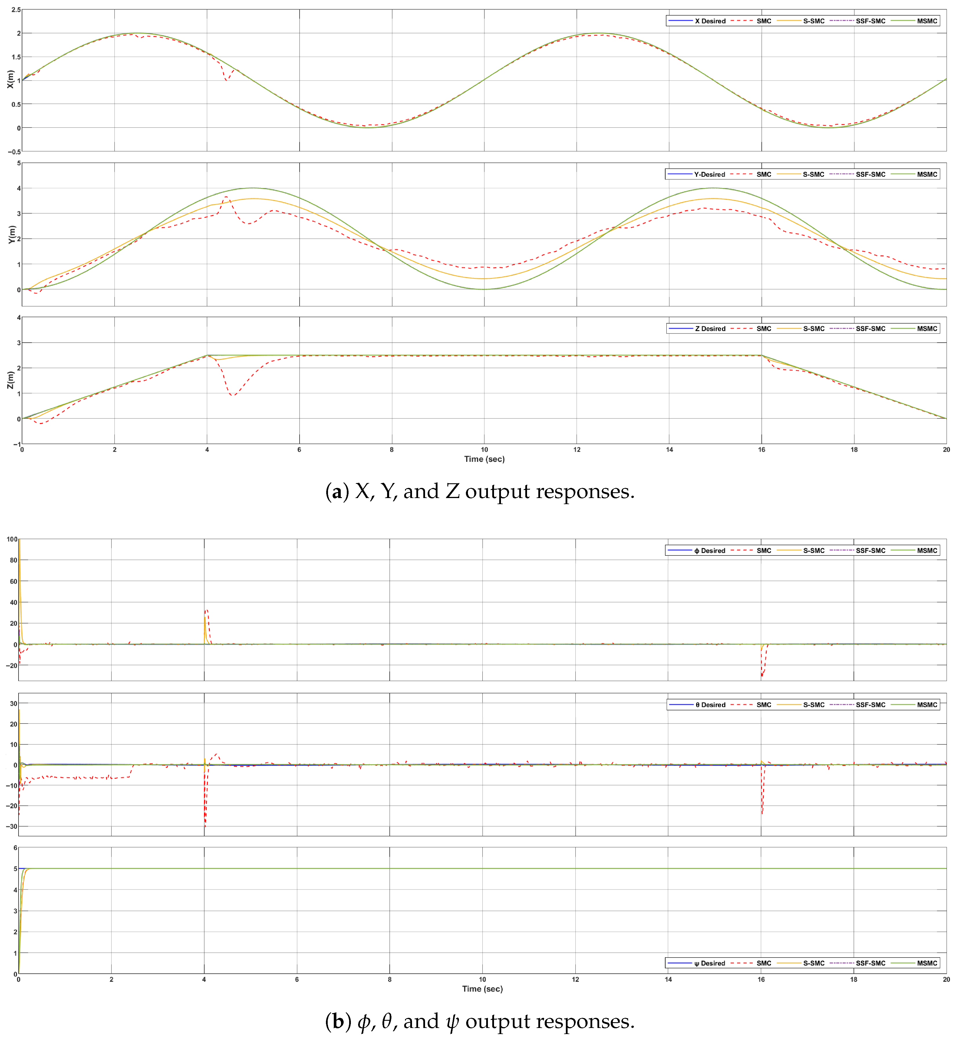
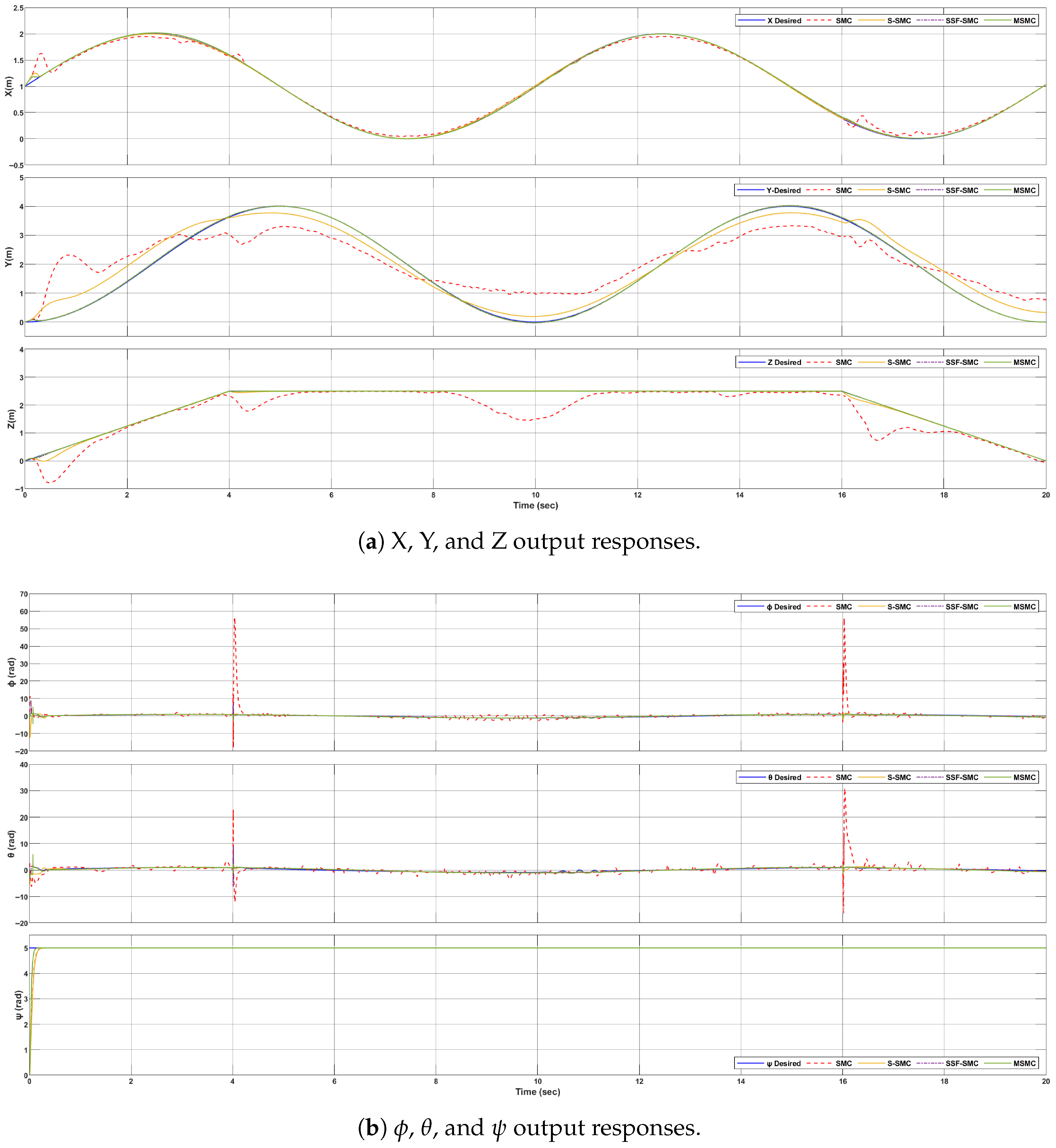
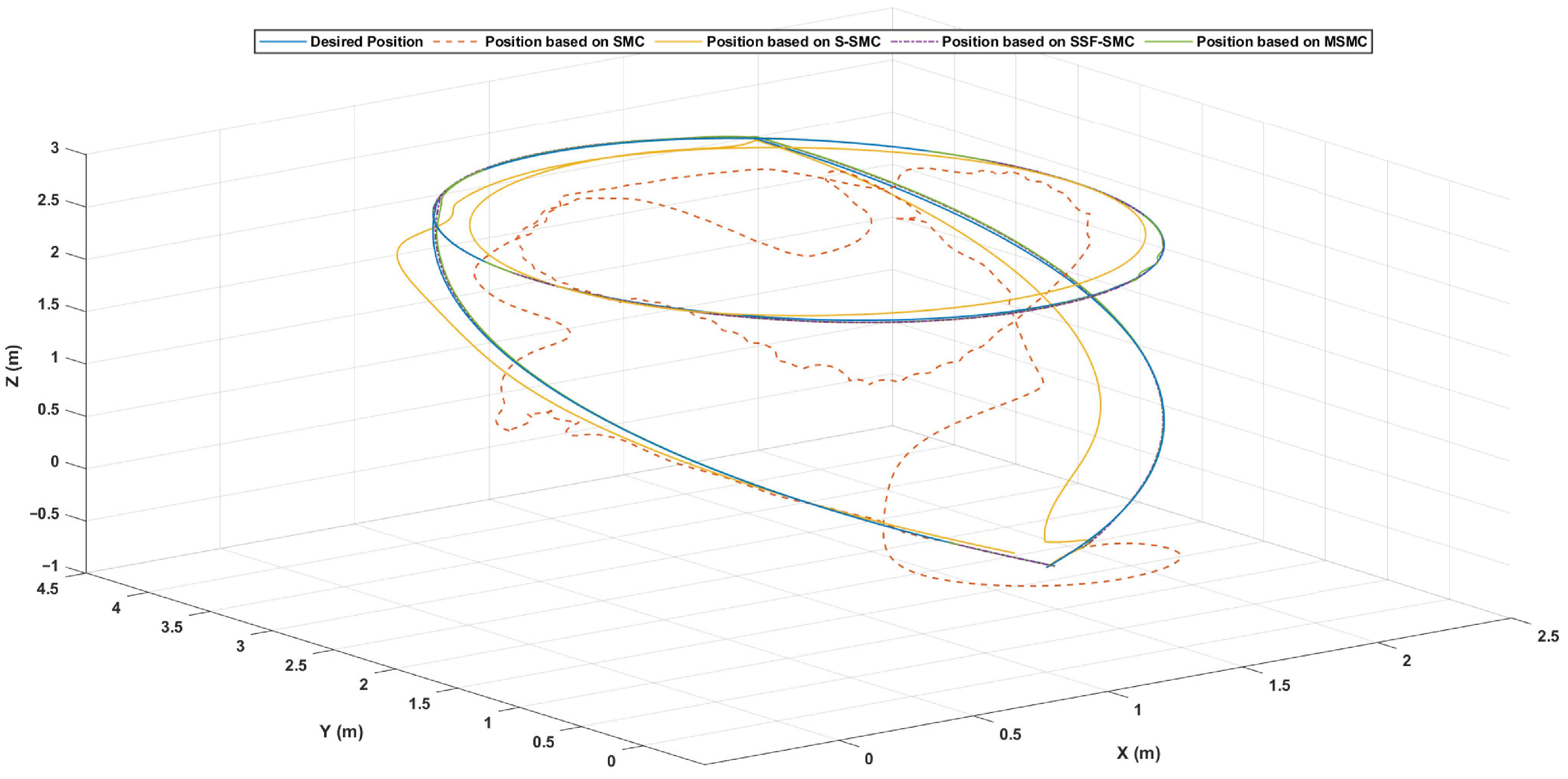
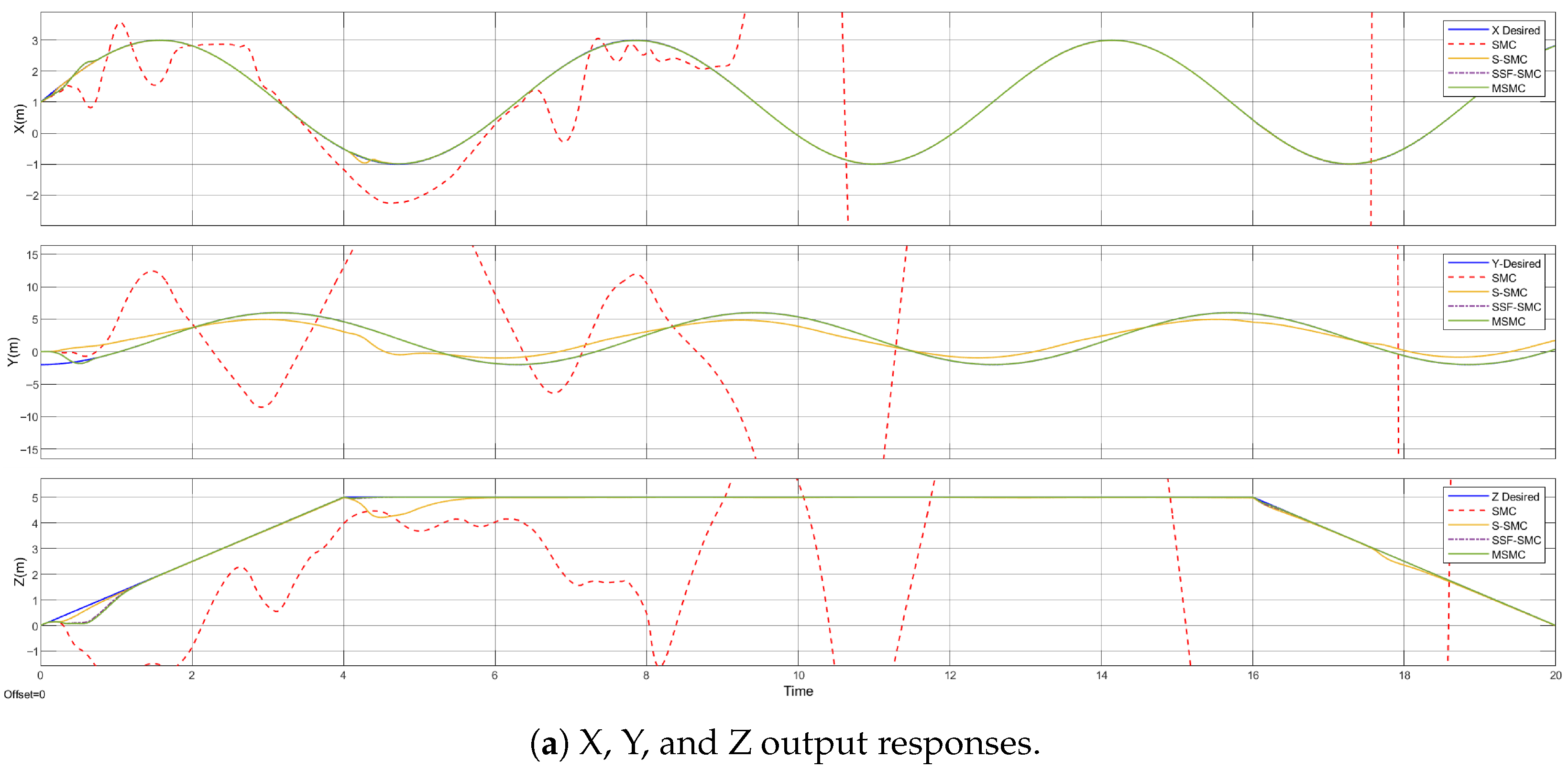
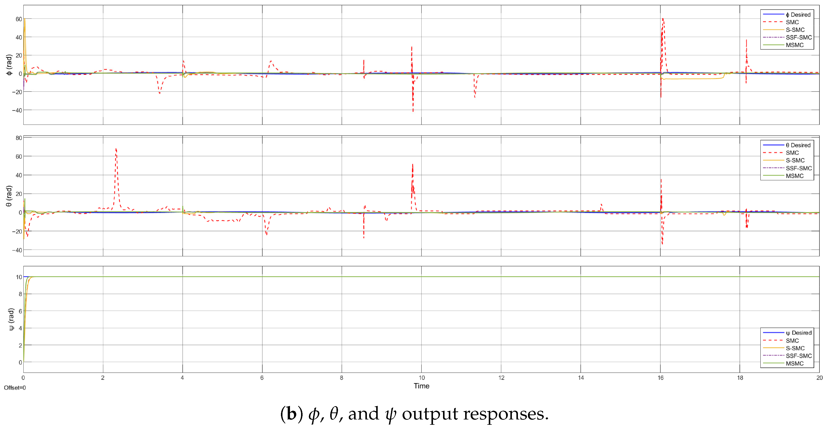
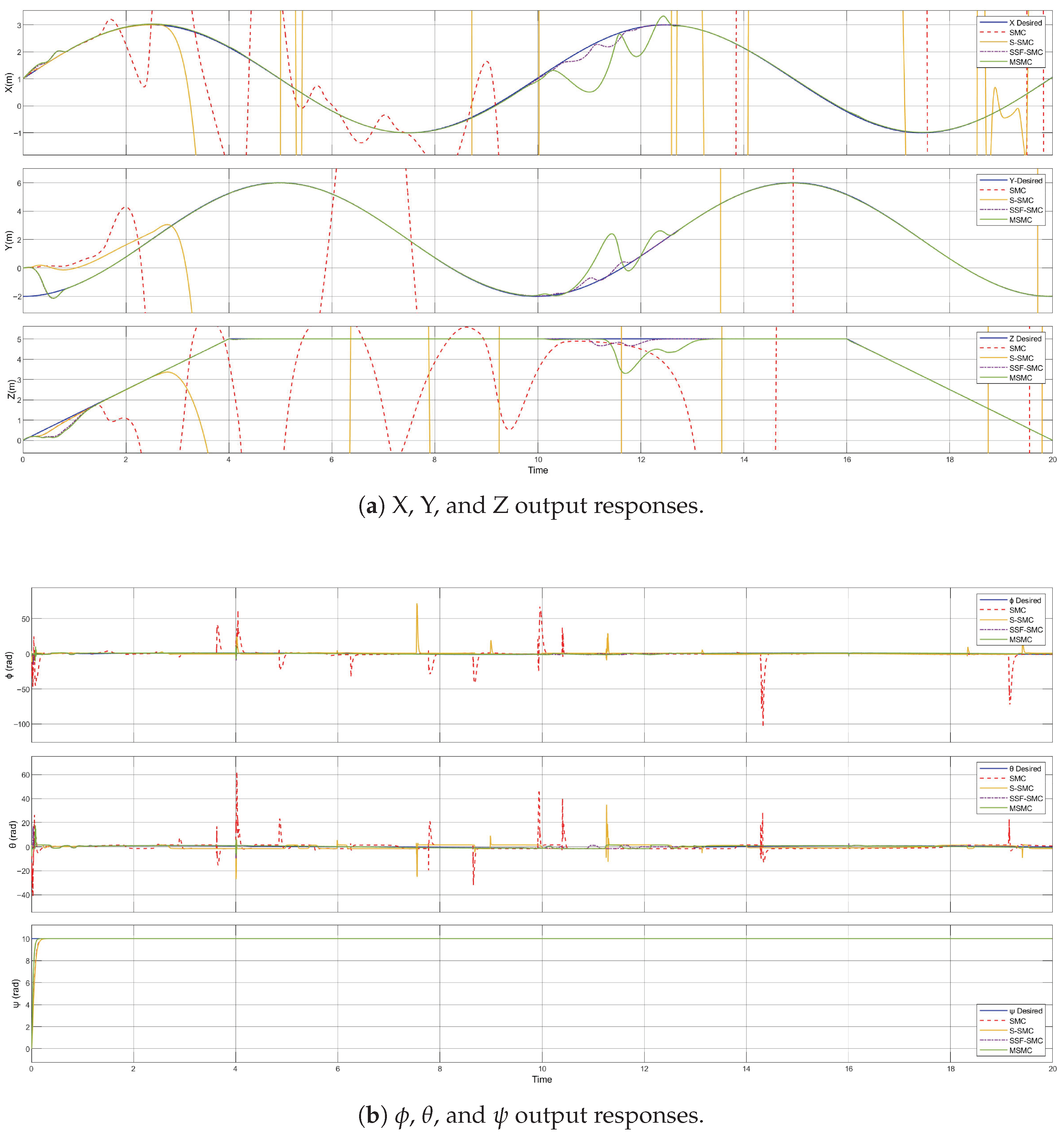
The external disturbances are applied to all six measured outputs, represented by disturbance terms d i = sin ( 0.5 t ) = [ d 1 , d 2 , d 3 , d 4 , d 5 , d 6 ] T . The simulation results for the quadcopter’s output responses in the absence and presence of external disturbances are presented in Figure 7 and Figure 8, respectively. The results demonstrate that the quadrotor is capable of accurately tracking the desired trajectory while effectively compensating for external disturbances. Additionally, Figure 7 and Figure 8 offer a comparative analysis of the position and attitude tracking performance achieved by the proposed controller against alternative control strategies. The proposed control–observer framework exhibits superior performance in both subsystems. Figure 9 shows the trajectory tracking positions in three-dimensional planes for the optimal controllers under disturbance conditions. The proposed controllers demonstrate a strong ability to reject disturbances, respond quickly, greatly reduce chattering issues, and deliver excellent tracking accuracy.
The improvement in the proposed controller’s performance relative to classical SMC in the presence of external disturbances can be evaluated using the following:
P I = 1 0.0835 7.7022 × 100 % = 98.92 % .
Meanwhile, the comparison of the proposed controller’s performance with the S-SMC in the presence of external disturbances can be evaluated using the following:
P I = 1 0.0835 2.1689 × 100 % = 96.16 % .
Also, the improvement in the proposed controller’s performance relative to the proposed SSF-SMC in the presence of external disturbances can be evaluated using the following:
P I = 1 0.0835 0.2128 × 100 % = 60.8 % .
Furthermore, Table 3 provides a summary comparison of the performance achieved by the optimal SMC controllers based on classical ERL, saturation ERL, SSF-ERL, and MSMC methods. The suggested controller outperforms classical SMC by reducing tracking errors during trajectory tracking flight conditions, even with disturbances, to 99.05% for roll, 99.26% for pitch, 40.18% for yaw, and 99.998% for altitude.

6.3. Trajectory Tracking Flight Under Input Variation in the Presence of Disturbances

The objective of this scenario is to test the quadrotor’s ability to follow a specified circular trajectory under the influence of varying input magnitudes and frequencies for the X, Y, and Z axes, and execute a landing maneuver accompanied by a 10° yaw rotation. The quadcopter was required to track the desired trajectory defined for t 0 :
[ x d , y d ] = 1 + 2 sin 2 π t 6.28 , 2 + 4 sin 2 π t 6.28 π 2
z d = 1.25 t for 0 t < 4 5 for 4 t 16 1.25 t for 16 < t < 20
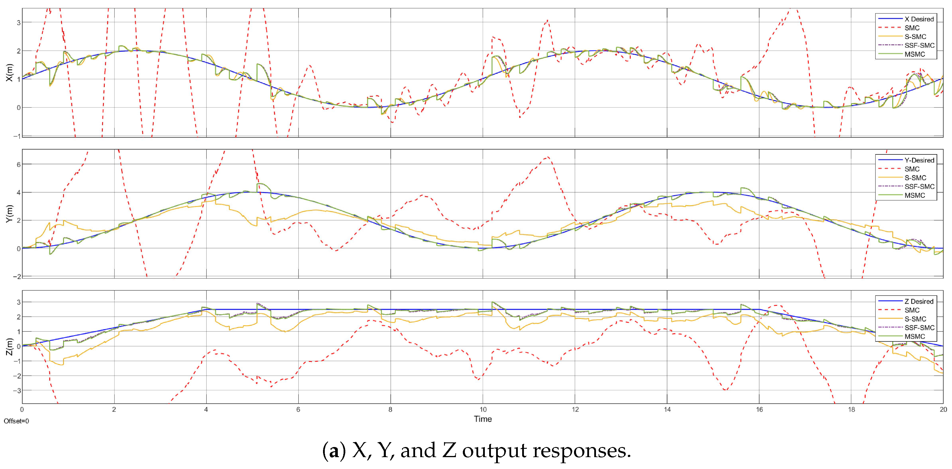
The same disturbances are applied uniformly to all six measured outputs. Therefore, the simulation results for the quadcopter’s output responses under input variation and the presence of disturbances are presented in Figure 10.
A more challenging test is conducted by reducing the landing angle to 2.5° yaw rotation and halving the nominal values of the desired X, Y, and Z inputs, as follows:
[ x d , y d ] = 1 + 0.5 sin 2 π t 6.28 , 2 + sin 2 π t 6.28 π 2
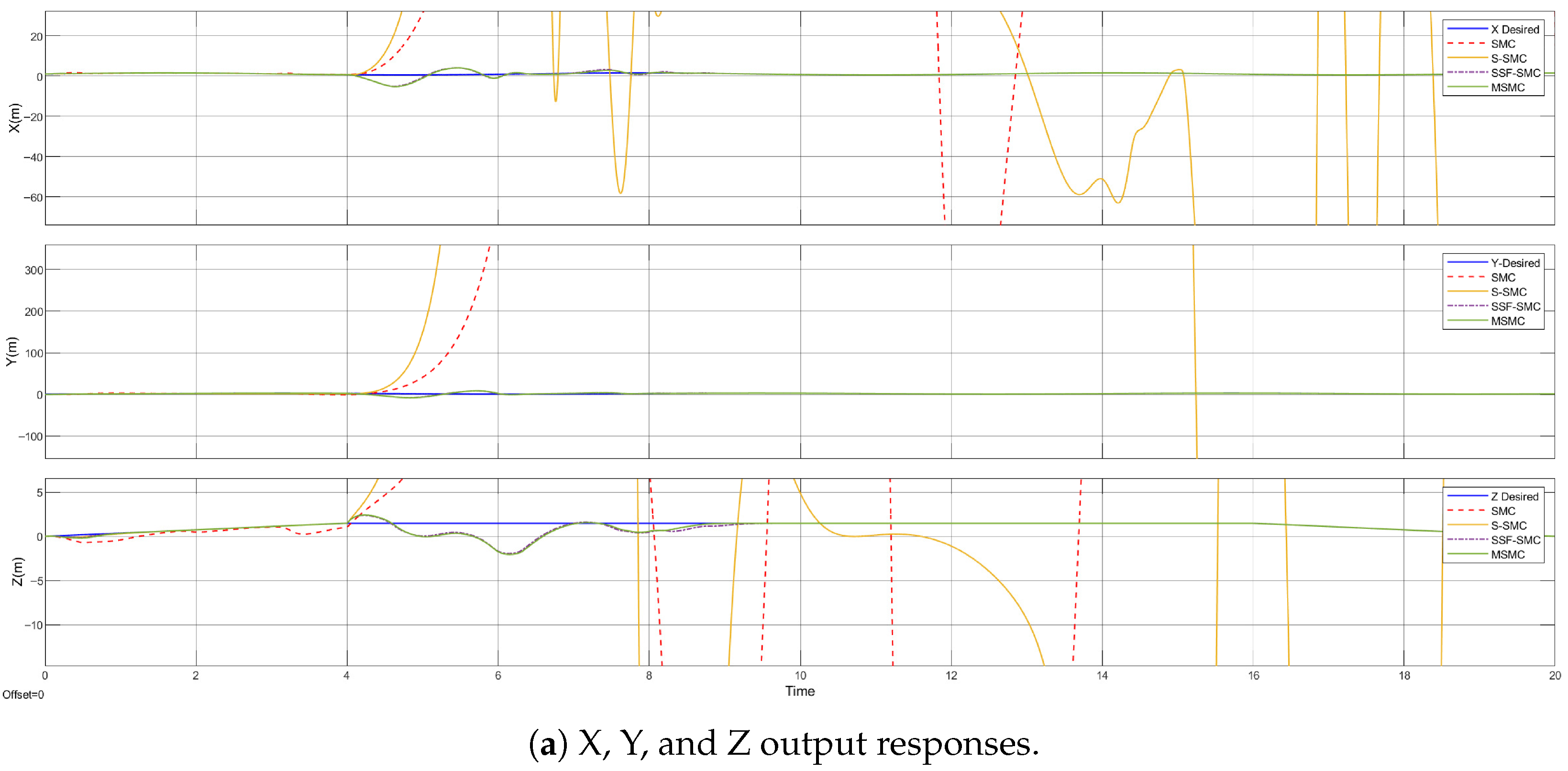
z d = 0.375 t for 0 t < 4 1.5 for 4 t 16 0.375 t for 16 < t < 20
The simulation results for the quadcopter’s output responses under another input variation test are presented in Figure 11. Figure 10 and Figure 11 prove that the proposed controller accurately tracks the desired trajectory and outperforms alternative control strategies in both position and attitude under input variation.

6.4. Trajectory Tracking Flight Under Random Noise and Parameter Variation in the Presence of Disturbances

To evaluate the robustness of the proposed controller against random noises, white band-limited noise with a power of 0.01, a sampling time of 0.3 s, and a seed value of 23341 was introduced to the quadcopter outputs. Figure 12 illustrates the resulting output responses for both position and attitude under the influence of this noise. It can be observed that the other control methods fail to compensate for the applied noise, resulting in significant deviations from the desired trajectory. In contrast, the proposed controller remains close to the reference value and achieves accurate tracking performance.
Furthermore, to perform a more extensive and complex test, all quadcopter parameters are varied by ± 200 % of their nominal values, while applying the same input variations used previously and the external disturbance. The output responses are shown in Figure 13 for the ± 200 % parameter variation scenario. These results highlight the robustness and adaptability of the control unit under complex conditions and varying system parameters. Such variations arise from the need to handle changing values in multiple scenarios. The findings confirm the effectiveness, reliability, and resilience of the control system.

7. Conclusions

This study concludes that the modified ERL based on SMC (MSMC) is an effective approach for controlling quadcopter UAV systems and ensuring accurate trajectory tracking. Compared to conventional SMC, MSMC offers enhanced precision and robustness, guarantees system convergence quickly, and eliminates the chattering effect. Simulation results confirmed that the proposed controller performs effectively under various flight conditions, including the presence of disturbances, noise, input variations, and parametric uncertainties. These findings demonstrate that the MSMC provides strong robustness, eliminates chattering, and achieves high-precision trajectory tracking with reduced settling and rise times. Although the MSMC shows excellent performance in simulations, the current study is limited to a simulated environment and specific unknown bounded disturbance scenarios. Real-world implementation may involve additional uncertainties such as sensor noise, wind gusts, and model inaccuracies. Future work should include experimental validation on a physical quadcopter platform, testing under more diverse environmental conditions, and further optimization of the control parameters to enhance adaptability and energy efficiency.

Author Contributions

Conceptualization, A.A.M.; methodology, A.A.M.; software, A.A.M.; validation, A.A.M.; formal analysis, A.A.M.; writing—original draft preparation, A.A.M.; writing—review and editing, A.A.M., F.G. and A.A.-K.; visualization, A.A.M.; funding acquisition, F.G. All authors have read and agreed to the published version of the manuscript.

Funding

This work has been supported by the Spanish Government through the projects PID2021-128327OA-I00 and TED2021-129374A-I00 funded by MCIU/AEI/10.13039/501100011033, by “ERDF A way of making Europe”, and by the European Union NextGenerationEU/PRTR.

Data Availability Statement

The original contributions presented in this study are included in the article; further inquiries can be directed to the corresponding author.

Conflicts of Interest

The authors declare that they have no known competing financial interests or personal relationships that could have appeared to influence the work reported in this paper.

References

  1. Bouabdallah, S.; Noth, A.; Siegwart, R. PID vs. LQ control techniques applied to an indoor micro quadrotor. In Proceedings of the 2004 IEEE/RSJ International Conference on Intelligent Robots and Systems (IROS) (IEEE Cat. No. 04CH37566), Sendai, Japan, 28 September–2 October 2004; IEEE: Piscataway, NJ, USA, 2004; Volume 3, pp. 2451–2456. [Google Scholar]
  2. Lopez-Sanchez, I.; Moreno-Valenzuela, J. PID control of quadrotor UAVs: A survey. Ann. Rev. Control 2023, 56, 100900. [Google Scholar] [CrossRef]
  3. Ayad, R.; Nouibat, W.; Zareb, M.; Bestaoui Sebanne, Y. Full control of quadrotor aerial robot using fractional-order FOPID. Iran. J. Sci. Technol. Trans. Electr. Eng. 2019, 43, 349–360. [Google Scholar] [CrossRef]
  4. Kayacan, E.; Maslim, R. Type-2 fuzzy logic trajectory tracking control of quadrotor VTOL aircraft with elliptic membership functions. IEEE/ASME Trans. Mechatron. 2016, 22, 339–348. [Google Scholar] [CrossRef]
  5. Tang, Y.R.; Xiao, X.; Li, Y. Nonlinear dynamic modeling and hybrid control design with dynamic compensator for a small-scale UAV quadrotor. Measurement 2017, 109, 51–64. [Google Scholar] [CrossRef]
  6. Saif, A.W.A.; Gaufan, K.B.; El-Ferik, S.; Al-Dhaifallah, M. Fractional order sliding mode control of quadrotor based on fractional order model. IEEE Access 2023, 11, 79823–79837. [Google Scholar] [CrossRef]
  7. Yongjun, D.; Jianhong, W.; Jinlong, Z.; Xi, L. Design of quadcopter attitude controller based on data-driven model-free adaptive sliding mode control. Int. J. Dyn. Control 2024, 12, 1404–1414. [Google Scholar] [CrossRef]
  8. Jinlong, Z.; Jianhong, W.; Ruchun, W.; Xi, L.; Yongjun, D.; Azar, A.T.; Ahmed, S.; Hameed, I.A.; Zalzala, A.M.; Ibraheem, I.K. Control Design of the Quadrotor Aircraft based on the Integral Adaptive Improved Integral Backstepping Sliding Mode Scheme. Eng. Technol. Appl. Sci. Res. 2024, 14, 17106–17117. [Google Scholar] [CrossRef]
  9. Razmi, H.; Afshinfar, S. Neural network-based adaptive sliding mode control design for position and attitude control of a quadrotor UAV. Aerosp. Sci. Technol. 2019, 91, 12–27. [Google Scholar] [CrossRef]
  10. Raffo, G.V.; Ortega, M.G.; Rubio, F.R. An integral predictive/nonlinear H∞ control structure for a quadrotor helicopter. Automatica 2010, 46, 29–39. [Google Scholar] [CrossRef]
  11. Besnard, L.; Shtessel, Y.B.; Landrum, B. Quadrotor vehicle control via sliding mode controller driven by sliding mode disturbance observer. J. Frankl. Inst. 2012, 349, 658–684. [Google Scholar] [CrossRef]
  12. Guo, L.; Xiong, W.; Zhao, H.; Song, Y.; Gan, D. A nearly optimal adaptive saturation function tuning method for quasi-sliding mode control based on integral reinforcement learning. Neurocomputing 2025, 623, 129363. [Google Scholar] [CrossRef]
  13. Ko, Y.R.; Hwang, Y.; Chae, M.; Kim, T.H. Direct identification of generalized Prandtl–Ishlinskii model inversion for asymmetric hysteresis compensation. ISA Trans. 2017, 70, 209–218. [Google Scholar] [CrossRef]
  14. Xiong, J.J.; Zheng, E.H. Position and attitude tracking control for a quadrotor UAV. ISA Trans. 2014, 53, 725–731. [Google Scholar] [CrossRef]
  15. Singla, M.; Shieh, L.S.; Song, G.; Xie, L.; Zhang, Y. A new optimal sliding mode controller design using scalar sign function. ISA Trans. 2014, 53, 267–279. [Google Scholar] [CrossRef]
  16. Abdelmaksoud, S.I.; Mailah, M.; Abdallah, A.M. Control strategies and novel techniques for autonomous rotorcraft unmanned aerial vehicles: A review. IEEE Access 2020, 8, 195142–195169. [Google Scholar] [CrossRef]
  17. Khalid, A.; Mushtaq, Z.; Arif, S.; Zeb, K.; Khan, M.A.; Bakshi, S. Control schemes for quadrotor UAV: Taxonomy and survey. ACM Comput. Surv. 2023, 56, 1–32. [Google Scholar] [CrossRef]
  18. El Gmili, N.; El Hamidi, K.; Mjahed, M.; El Kari, A.; Ayad, H. Intelligent sliding mode control for quadrotor trajectory tracking under external disturbances. Electrica 2024, 24, 1–14. [Google Scholar] [CrossRef]
  19. Bouadi, H.; Bouchoucha, M.; Tadjine, M. Sliding mode control based on backstepping approach for an UAV type-quadrotor. World Acad. Sci. Eng. Technol. 2007, 26, 22–27. [Google Scholar]
  20. Xu, G.; Xia, Y.; Zhai, D.H.; Ma, D. Adaptive prescribed performance terminal sliding mode attitude control for quadrotor under input saturation. IET Control Theory Appl. 2020, 14, 2473–2480. [Google Scholar] [CrossRef]
  21. Liu, J. Sliding Mode Control Using MATLAB; Academic Press: Cambridge, MA, USA, 2017. [Google Scholar]
  22. Fang, J.; Zhang, L.; Long, Z.; Wang, M.Y. Fuzzy adaptive sliding mode control for the precision position of piezo-actuated nano positioning stage. Int. J. Precis. Eng. Manuf. 2018, 19, 1447–1456. [Google Scholar] [CrossRef]
  23. Sun, X.; Zhu, Y.; Cai, Y.; Yao, M.; Sun, Y.; Lei, G. Optimized-sector-based model predictive torque control with sliding mode controller for switched reluctance motor. IEEE Trans. Energy Convers. 2023, 39, 379–388. [Google Scholar] [CrossRef]
  24. Kennedy, J.; Eberhart, R. Particle swarm optimization. In Proceedings of the ICNN’95-International Conference on Neural Networks, Perth, WA, Australia, 27 November–1 December 1995; IEEE: Piscataway, NJ, USA, 1995; Volume 4, pp. 1942–1948. [Google Scholar]
  25. Eberhart, R.; Kennedy, J. A new optimizer using particle swarm theory. In Proceedings of the MHS’95, the Sixth International Symposium on Micro Machine and Human Science, Nagoya, Japan, 4–6 October 1995; IEEE: Piscataway, NJ, USA, 1995; pp. 39–43. [Google Scholar]
  26. Wang, D.; Tan, D.; Liu, L. Particle swarm optimization algorithm: An overview. Soft Comput. 2018, 22, 387–408. [Google Scholar] [CrossRef]
  27. Shi, Y.; Eberhart, R. A modified particle swarm optimizer. In Proceedings of the 1998 IEEE International Conference on Evolutionary Computation Proceedings, IEEE World Congress on Computational Intelligence (Cat. No. 98TH8360), Anchorage, AK, USA, 4–9 May 1998; IEEE: Piscataway, NJ, USA, 1998; pp. 69–73. [Google Scholar]
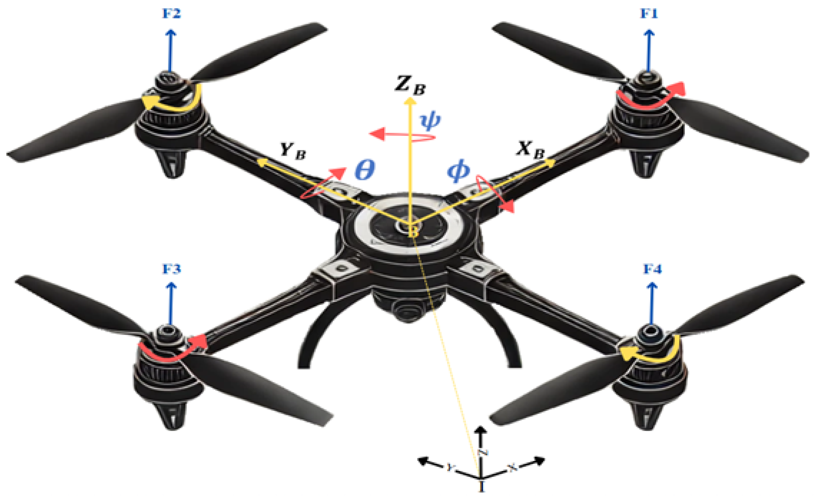
Figure 1. Schematic of a UAV quadcopter.
Drones 09 00737 g001
Figure 2. Block diagram of quadcopter system controllers.
Drones 09 00737 g002
Figure 3. The different nonlinear SSFs based on different values of ε ; when ε = 0 , it signifies the signum function.
Drones 09 00737 g003
Figure 4. Block diagram of the proposed optimal adaptive SMC based on modified ERL.
Drones 09 00737 g004
Figure 5. Trajectory tracking results for the optimal controllers in the hovering flight scenario.
Drones 09 00737 g005
Figure 6. Control signals for the optimal controllers in the hovering flight scenario.
Drones 09 00737 g006
Figure 7. Trajectory tracking results for the optimal controllers in the absence of disturbances.
Drones 09 00737 g007
Figure 8. Trajectory tracking results for the optimal controllers in the presence of disturbances.
Drones 09 00737 g008
Figure 9. Trajectory tracking position in the three-dimensional planes for the optimal controllers in the presence of disturbances.
Drones 09 00737 g009
Figure 10. Trajectory tracking results for the optimal controllers under input variation.
Drones 09 00737 g010aDrones 09 00737 g010b
Figure 11. Trajectory tracking results under the influence of half the nominal input values for the optimal controllers.
Drones 09 00737 g011aDrones 09 00737 g011b
Figure 12. Trajectory tracking results under the influence of random noise for the optimal controllers.
Drones 09 00737 g012aDrones 09 00737 g012b
Figure 13. Trajectory tracking results under parameter variation ± 200 % of the nominal parameter values for the optimal controllers.
Drones 09 00737 g013
Table 1. Quadcopter dynamic model parameters [18,19,20].
ParameterDefinitionValue
bThrust coefficient 2.9842 × 10 5 N·m/rad/s
dDrag coefficient 3.232 × 10 7 N·m/rad/s
gGravity acceleration 9.806   m / s 2
I x Inertia around x-axis 0.0075   kg·m 2
I y Inertia around y-axis 0.0075   kg·m 2
I z Inertia around z-axis 0.013   kg·m 2
J r Rotor inertia 2.8385 × 10 5   N·m / rad / s 2
K f a x Aerodynamic friction coefficient in x 5.567 × 10 4 N/rad/s
K f a y Aerodynamic friction coefficient in y 5.567 × 10 4 N/rad/s
K f a z Aerodynamic friction coefficient in z 6.354 × 10 4 N/rad/s
K f t x Translational drag coefficient in x 5.567 × 10 4 N/m/s
K f t y Translational drag coefficient in y 5.567 × 10 4 N/m/s
K f t z Translational drag coefficient in z 6.354 × 10 4 N/m/s
lQuadcopter arm length 0.23 m
mQuadcopter mass 0.65 kg
Table 2. Optimal controller parameters for the quadcopter UAV system based on different functions in ERL.
Quadcopter OutputOptimal ParameterSign FunctionSaturation FunctionSSFModified ERL
ϕ k 1 * 3.752430.000017.998167.94719
λ 1 * 67.03035212.80940124.86942153.14592
R 1 * 1.48729
θ k 2 * 0.000012.896511.272730.08776
λ 2 * 82.44825175.80519173.86590132.69362
R 2 * 4.17532
ψ k 3 * 3.740080.815391.414736.96150
λ 3 * 49.2694173.23008185.83627171.37256
R 3 * 0.27411
x k 4 * 0.000016.005472.8919618.15754
λ 4 * 2.133313.697063.407993.04928
R 4 * 1.57180
y k 5 * 0.000012.482973.9782548.46309
λ 5 * 3.915194.260764.221602.79202
R 5 * 0.00001
z k 6 * 0.538391.263972.3601235.56046
λ 6 * 4.990336.176525.698866.81947
R 6 * 1.40125
Table 3. Performance results for SMC, S-SMC, SSF-SMC, and MSMC controllers based on the PSO method.
Quadcopter OutputPerformance IndexSMCS-SMCSSF-SMCMSMC
ϕ ISE10.02080.00260.00830.0008
MSE12.37441.25380.05400.0226
θ ISE20.02730.00980.00760.0004
MSE24.59950.77660.05210.0343
ψ ISE30.62870.42170.16340.0347
MSE30.04370.04570.03700.0262
xISE40.33880.31570.27820.2492
MSE40.00411.2738 × 10−42.0740 × 10−41.3440 × 10−4
yISE51.71651.51381.21611.0743
MSE50.48630.09113.5796 × 10−42.1168 × 10⁻⁴
zISE61.09570.87600.90910.8459
MSE60.19410.00161.9995 × 10−43.9379 × 10⁻⁶
Total CF15.25444.17623.47482.9630
Total CF27.70222.16890.21280.0835
Disclaimer/Publisher’s Note: The statements, opinions and data contained in all publications are solely those of the individual author(s) and contributor(s) and not of MDPI and/or the editor(s). MDPI and/or the editor(s) disclaim responsibility for any injury to people or property resulting from any ideas, methods, instructions or products referred to in the content.