Next Article in Journal
Dynamic Self-Triggered Fuzzy Formation Control for UAV Swarm with Prescribed-Time Convergence
Previous Article in Journal
An Underwater Salvage Robot for Retrieving Foreign Objects in Nuclear Reactor Pools
 
 
Correction to Drones 2025, 9(9), 661.
Correction

Correction: Liu et al. UAV Path Planning in Threat Environment: A*-APF Algorithm for Spatio-Temporal Grid Optimization. Drones 2025, 9, 661
1
Equipment Management and Unmanned Aerial Vehicle Engineering School, Air Force Engineering University, Xi’an 710051, China
2
National Key Laboratory of Unmanned Aerial Vehicle Technology, Xi’an 710051, China
3
The Youth Innovation Team of Shaanxi University, Xi’an 710051, China
*
Author to whom correspondence should be addressed.
Drones 2025, 9(10), 713; https://doi.org/10.3390/drones9100713
Submission received: 29 September 2025 / Accepted: 2 October 2025 / Published: 15 October 2025
Error in Figure/Table
In the original publication [1], there was a mistake in Figure 2 (Spatial Grid Subdivision Schematic Diagram) as published. The original Figure 2 included redundant details of binary encoding (e.g., specific binary conversion steps for degrees, minutes, and seconds, tedious splicing diagrams of Morton encoding, and redundant bit-by-bit description of 32-bit encoding) which were not only confusing to readers but also had weak relevance to the core algorithm design (hybrid A*-APF algorithm). These redundant contents violated the reviewer’s suggestion of “focusing on algorithm design”. The corrected Figure 2 appears below. The authors state that the scientific conclusions are unaffected. This correction was approved by the Academic Editor. The original publication has also been updated.
Corrected Figure 2 Description:
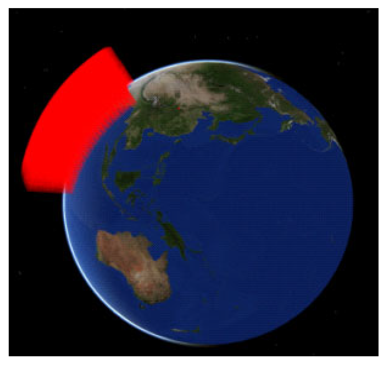
The corrected Figure 2 has removed all redundant grid subdivision rules and binary encoding details, retaining only the core elements of spatial grid division that support subsequent environmental modeling. The actual shape of the globally subdivided grid is shown in Figure 2 (original Figure 2f), highlighting the continuous and seamless characteristics of the 3D grid to ensure readers understand the supporting role of the grid in environmental modeling.
Figure 2. Actual shapes of spatial grid.
Drones 09 00713 g002
Text Correction
There was an error in the original publication. The original Section 2.1.1 “Spatial Grid Division” contained excessive redundant grid encoding details (e.g., step-by-step decomposition of 32-bit binary encoding for latitude/longitude, bit-by-bit description of degree-minute-second-sub-second encoding, tedious splicing steps of multi-dimensional encoding) which were confusing to readers and had low relevance to the core achievement of this paper (the hybrid A*-APF algorithm for UAV path planning). This violated Reviewer 1’s Comment 2: “I don’t understand why so much Encoding stuff is explained in Section 2.1.1. This is a bit confusing and does not have much to do with the algorithm design.”
A correction has been made to Section 2.1 “Spatio-Temporal Grid Modeling”, Section 2.1.1 “Spatial Grid Division”, Paragraphs 1–5:
Corrected Section 2.1.1 Spatial Grid Division
To address the processing requirements of multi-source data in complex environments, this paper proposes a spatial environment modeling method based on a global subdivision grid system, aiming to provide a unified structured representation and computational framework for airspace data in UAV missions.
Based on the fundamental theory of three-dimensional subdivided grids in geospatial, this method conducts grid modeling of the airspace environment for UAV. The benchmark for spatial grid subdivision is set as the Earth’s reference ellipsoid, and a three-dimensional orthogonal coordinate system is established with the intersection of the prime meridian and the equatorial plane as the origin. The grid coverage spans globally in the longitudinal direction (±180°) and the latitudinal direction (±90°), extending from −6302 km below the Earth’s surface to 528,680 km above it in the vertical direction, forming a multi-level grid system with seamless global coverage. The hierarchical division strictly follows the principles of equal longitude-latitude differences and equal altitude differences, constructing a continuous, seamless, and non-overlapping multi-level three-dimensional grid system through progressive subdivision, with the smallest-volume element reaching the centimeter scale.
In terms of latitude and longitude, the grid levels are divided according to spatial resolution: Levels 1–9 represent degree-level grids, Levels 10–13 represent minute-level grids, Levels 14–17 represent second-level grids, and Levels 18–25 represent below second-level grids.
In the vertical direction, the grid levels are divided by resolution: Levels 1–15 represent kilometer-scale grids, Levels 16–17 represent hundred-meter-scale grids, Levels 18–19 represent ten-meter-scale grids, Levels 20–21 represent meter-scale grids, and Levels 22–23 represent centimeter-scale grids. The minimum scale is at the ten-centimeter level, which meets the requirements of UAV mission planning. The actual subdivision effect is shown in Figure 2.
After completing spatial grid subdivision, it is necessary to assign unique encodings to grid cells to determine their spatial positions. This study adopts a binary encoding scheme to support airspace grid calculations.
  • Coding length and level identification. The coding length for each dimension is fixed at 32 binary digits. For a given level (N2 = 13), the effective number of bits is 16. Therefore, the latter 16 bits of the latitude coding (the level identification code element part) consist of 1 bit of “0” (indicating the end of the level) and 15 bits of “1” (padding bits). Similarly, the effective number of bits for the height level N3 = 16 is 18.
  • Encoding Latitude and Longitude. For latitude (34°24′58.379″ N), the first code element: the Northern Hemisphere (N) is identified as “0”; the degree value (34°) is converted to a 9-bit binary number “000100010” (with leading zeros to make 9 bits); the minute value (24′) is converted to a 7-bit binary number “0101100”; the second value (58″) is converted to a 7-bit binary number “1110011”; the fractional part of the second (0.379″) is converted to an 8-bit binary number “01100001”. Combining these parts and adding a 1-bit level identifier (the first “0” in the last 16 bits mentioned in Step 1), we obtain the complete 32-bit latitude code “0001000100101100111001101100001”. Based on an effective bit length of 16, the latitude code under N2 = 13 is “00010001001011000111111111111111”. Similarly, the longitude (109°3′41.260″ E) is encoded as “00110110100000110111111111111111111”.
  • Two-dimensional plane encoding. The obtained 32-bit latitude encoding and 32-bit longitude encoding are combined using Morton ordering to generate a unique 64-bit two-dimensional plane encoding. The result in this example is “0000011100010110010010001010010100111111111111111111111111111111”.
  • Height encoding. Based on an effective bit length of 18, the height encoding under N3 = 16 is “00000001000110000001111111111111”. See Figure 3 for a detailed diagram of the encoding process.
    Figure 3. Three-dimensional coding conversion example.
    Figure 3. Three-dimensional coding conversion example.
    Drones 09 00713 g003

Reference

  1. Liu, L.; Ru, L.; Wang, W.; Xi, H.; Zhu, R.; Li, S.; Zhang, Z. UAV Path Planning in Threat Environment: A*-APF Algorithm for Spatio-Temporal Grid Optimization. Drones 2025, 9, 661. [Google Scholar] [CrossRef]
Disclaimer/Publisher’s Note: The statements, opinions and data contained in all publications are solely those of the individual author(s) and contributor(s) and not of MDPI and/or the editor(s). MDPI and/or the editor(s) disclaim responsibility for any injury to people or property resulting from any ideas, methods, instructions or products referred to in the content.