Article

UAV Equipped with SDR-Based Doppler Localization Sensor for Positioning Tactical Radios †

by
Kacper Bednarz
,
Jarosław Wojtuń
*,
Rafał Szczepanik
and
Jan M. Kelner
Institute of Communications Systems, Faculty of Electronics, Military University of Technology, 00-908 Warsaw, Poland
*
Author to whom correspondence should be addressed.
The paper is an extended version of paper Bednarz K.; Wojtuń J.; Szczepanik R. Localization Accuracy Assessment of Tactical Radio based on Acoustic Doppler Effect in Laboratory Conditions, presented at the 2024 International Radar Symposium 2024 (IRS) on the 2024 11th Microwave and Radar Week (MRW), Wroclaw, Poland, 1–4 July 2024.
Drones 2025, 9(10), 698; https://doi.org/10.3390/drones9100698 (registering DOI)
Submission received: 1 August 2025 / Revised: 18 September 2025 / Accepted: 8 October 2025 / Published: 11 October 2025

Abstract

Highlights

What are the main findings?
  • A novel UAV-mounted Doppler-based SDR sensor system was developed and validated for localizing realistic tactical radio emitters.
  • The system achieves accurate localization (average error below 50 m) in real-world conditions without relying on multiple UAVs or external infrastructure.
What is the implication of the main finding?
  • The proposed method enables flexible, cost-effective RF emitter localization suitable for critical infrastructure protection, public safety, and spectrum management.
  • The research confirms the safe and responsible use of dual-use technology, adhering to ethical and regulatory standards, with no threat to public health or national security.

Abstract

The accurate localization of radio frequency (RF) emitters plays a critical role in spectrum monitoring, public safety, and defense applications, particularly in environments where global navigation satellite systems are limited. This study investigates the feasibility of a single unmanned aerial vehicle (UAV) equipped with a Doppler-based software-defined radio sensor to localize modern RF sources without the need for external infrastructure or multiple UAVs. A custom-designed localization system was developed and tested using the L3Harris AN/PRC-152A tactical radio, which represents a class of real-world, dual-use emitters with lower frequency stability than laboratory signal generators. The approach was validated through both emulation studies and extensive field experiments under realistic conditions. The results show that the proposed system can localize RF emitters with an average error below 50 m in 80% of cases even when the transmitter is more than 600 m away. Performance was evaluated across different carrier frequencies and acquisition times, demonstrating the influence of signal parameters on localization accuracy. These findings confirm the practical applicability of Doppler-based single-UAV localization methods and provide a foundation for further development of lightweight, autonomous RF emitter tracking systems for critical infrastructure protection, spectrum analysis, and tactical operations.

1. Introduction

The localization of radio frequency (RF) emitters is a fundamental and challenging problem that has gained increasing significance across various industries, including telecommunications, public safety, environmental monitoring, and critical infrastructure management. Accurate RF localization is essential for spectrum monitoring, interference mitigation, and ensuring communication reliability. However, the task remains difficult due to factors such as the frequency instability of device clocks, multipath propagation, and the limited coverage of traditional ground-based localization systems. In this context, modern technologies such as unmanned aerial vehicles (UAVs) offer a flexible, mobile, and cost-effective platform that can overcome many of these limitations by providing improved coverage, mobility, and accuracy in Global Positioning System (GPS)-denied or complex environments.
In recent years, substantial progress has been made in the development of UAV-based localization technologies, particularly in Global Positioning System (GPS)-denied environments, where traditional positioning systems face significant limitations. The authors of [1] present a comprehensive review of RF-based localization technologies for UAVs, emphasizing the growing need for alternative solutions in confined spaces. Among various technologies, such as vision-based systems, inertial navigation systems (INS), ultrasonic sensors, and light detection and ranging (LIDAR), RF-based solutions stand out for their low cost, low latency, and high accuracy. Time-based positioning using ultra-wideband (UWB) is highlighted as one of the most reliable approaches, although its dependency on anchor nodes presents a critical limitation. The potential of sensor fusion methods, which combine RF with other positioning technologies, is also discussed as a promising way to overcome these challenges.
Innovative approaches to UAV-based localization have also been proposed using passive and active methods. For instance, [2] introduces a method for target localization using UAVs and angle-of-arrival (AOA) information derived from aerial images, eliminating the need for complex parameters like focal length and elevation. This approach leverages a dynamic navigation system to synchronize multiple UAVs, resulting in improved accuracy through cooperative data integration.
An alternative perspective is provided in [3], where the focus is on RF signal source localization using an autonomous UAV with predefined waypoints. This study proposes several linear least squares (LLS) algorithms to improve real-time localization accuracy while balancing computational complexity and battery constraints. The results reveal that selecting optimal anchor positions along a UAV’s trajectory significantly enhances localization performance, making these algorithms suitable for practical applications.
Active geolocation methods have also demonstrated significant improvements in precision. In [4], a UAV platform equipped with electro-optical sensors and a laser range-finder is used for high-accuracy geolocation of stationary ground targets. By integrating multiple angle and range measurements with weighted least square estimation, the method achieves remarkable localization accuracy, especially after correcting for mounting errors between the navigation module and electro-optical device.
The integration of multiple UAVs for cooperative target localization has been explored as an effective solution for enhancing localization accuracy and speed in electronic warfare environments. In [5], a novel method leverages spatial coherence and cooperative beamforming among multiple UAVs, enabling high-precision passive localization with reduced accumulation time. Simulation results confirm that this multi-UAV approach outperforms traditional direction-finding methods, offering a more efficient solution for real-time ground target tracking.
In the context of electronic warfare, work [6] introduces a mathematical model for cross-location operations by UAVs, addressing the critical challenge of location ambiguity. The proposed model provides a quantitative relationship between localization precision and ambiguity, offering valuable insights for military reconnaissance and electronic countermeasure missions. The study’s computational simulations validate the model’s practicality, demonstrating its potential for improving UAV deployment strategies in complex operational environments.
A different angle is presented in [7], where a ground target localization algorithm based on UAV aerial image analysis is proposed. By integrating multiple visual features such as color histograms, generalized local orientation matrix (GLOM) texture features, and radiative transformation models, this approach refines coarse positioning results and achieves superior accuracy compared to single-feature methods. The experimental validation of this algorithm demonstrates its effectiveness in advancing UAV-based image analysis and enhancing computer vision applications for ground target localization.
Whereas, a comprehensive review of short-distance localization techniques for UAVs, with a strong emphasis on UWB technology is discussed in [8]. The authors explore various localization methods, including RF-based, visual, and inertial approaches, and highlight UWB’s suitability for precise positioning in GPS-denied environments, such as indoor spaces or UAV swarm operations. The paper also discusses sensor fusion strategies and provides an in-depth comparison of accuracy, scalability, and power efficiency across different localization systems. Complementary to this, the authors of [9] review deep learning-based absolute visual localization methods, which aim to match current UAV camera views with georeferenced imagery. Their work highlights the growing role of vision-based artificial intelligence (AI) techniques in enhancing UAV localization performance, particularly when integrated with traditional methods.
The above-mentioned studies focus predominantly on localization systems that require multiple UAVs, such as those designed for cooperative or swarm-based operations. This is mainly due to the inherent characteristics of the localization methods employed. Some approaches rely on external infrastructure, such as communication with multiple anchor points in UWB systems. Moreover, multi-UAV systems often involve additional complexities, including the need to synchronize multiple onboard sensors or predefine flight trajectories.
In contrast, the use of a single UAV equipped with a Doppler-based localization sensor represents a fundamentally different approach. Although we have previously introduced this concept [10,11], in this paper we demonstrate for the first time its effectiveness in localizing an L3Harris AN/PRC-152A tactical radio in a real-world environment. The preparatory stage for these experimental studies was emulation tests using this tactical radio. The emulation investigations described in this paper extend those presented in [12]. It is worth emphasizing that tactical radios are characterized by lower frequency stability compared to the signal generators or software-defined radios (SDRs) commonly used in experimental setups as RF emitters, which are often stabilized by external atomic clocks, such as rubidium frequency standards [13]. In frequency-based localization methods, the frequency stability of both the emitter (i.e., transmitter (Tx)) and receiver (Rx) clocks plays a critical role. Therefore, the approach presented in this paper provides a more realistic assessment of the developed sensor capabilities in relation to the typical characteristics of real-world RF emitters.
Modern communication devices, such as the L3Harris® AN/PRC-152A wideband networking handheld radio, exemplify the current state of advancement in radio technology. The AN/PRC-152A is a multiband, multimode radio capable of operating across a frequency ranges from 30 MHz to 512 MHz and from 762 MHz to 870 MHz, supporting a variety of analog and digital modulations. Designed for both voice and data transmission, this radio offers compatibility with multiple waveforms and protocols, making it a highly versatile communication tool in many industrial and public safety applications. The radio is primarily used by the United States (US) and North Atlantic Treaty Organization (NATO) armies but are also utilized by civilian and paramilitary forces in specific situations, especially where a reliable, encrypted, and interoperable communications link is required. So, it can be considered a dual-use technology. You may find examples of its use by US emergency services and homeland security agencies (e.g., the Federal Emergency Management Agency (FEMA), some fire and police departments), humanitarian aid organizations in conflict zones (e.g., the United Nations or Red Cross), special services and police tactical units (e.g., Special Weapons and Tactics (SWAT)), civil defense services during exercises (e.g., in blackout scenarios), and research or expedition missions (e.g., in the Arctic). Its robust design, frequency agility, and reliable performance under diverse conditions pose unique challenges for accurate RF emitter localization, particularly when traditional fixed-sensor networks are used.
This study investigates the practical application of a single UAV-mounted localization sensor for detecting and positioning modern RF emitters in real-world environments, using the L3Harris AN/PRC-152A as a representative example. By integrating a custom-designed Doppler-based SDR sensor with a commercial UAV platform, the approach leverages UAV mobility and aerial perspective to enhance signal reception and localization accuracy, overcoming many limitations of traditional ground-based systems. Through extensive field testing, this research bridges the gap between theoretical developments and practical implementation, contributing to ongoing efforts in electromagnetic spectrum analysis. The proposed solution holds promise for a range of applications, including critical infrastructure protection, spectrum monitoring, and dual-use industrial operations, laying the groundwork for future advancements in UAV-based RF localization technologies.
RF emitter localization spans methods that trade infrastructure, synchronization, and computational cost for accuracy. Single-UAV Doppler-only approaches are attractive for scenarios prioritizing rapid deployment and minimal infrastructure because they avoid external anchors and tight time/frequency synchronization. In this work, we consider positioning a non-cooperative narrowband emitter using a single UAV that measures Doppler frequency shifts (DFS) along a known trajectory. The carrier frequency of the transmitted signal is not precisely known and may drift, and no synchronization or side information is assumed. Under line-of-sight (LOS) conditions with navigation-grade pose knowledge, we estimate the instantaneous DFSs in the receiving signal over short acquisition windows (optionally aided by a companion sensor for carrier stabilization). The emitter position coordinates are approximated in the next steps based on the updated DFS vector and the signal Doppler frequency (SDF) method. We evaluate accuracy in emulation tests and field trials with a realistic tactical handheld radio. We analyze how carrier frequency and acquisition time affect the statistics of location error, providing guidance for rapid, infrastructure-light deployments. This framing connects the method and hardware with the experimental validation.
The main contributions of this paper are as follows:
  • We propose a novel RF emitter localization method based solely on Doppler frequency measurements from a single UAV-mounted SDR sensor, eliminating the need for multi-UAV synchronization or fixed ground-based infrastructure.
  • We develop and validate a custom-designed localization system capable of detecting and tracking modern tactical radios characterized by limited frequency stability, such as the L3Harris AN/PRC-152A.
  • We demonstrate the effectiveness of the proposed system through a combination of emulation studies and real-world field experiments, showing that meter-scale accuracy can be achieved under realistic conditions.
  • We provide a critical analysis of system performance across carrier frequencies and acquisition times, identifying practical limitations as well as application domains such as spectrum monitoring, infrastructure protection, and search and rescue (SAR) missions.
The remainder of the paper is organized as follows. Section 2 describes the theoretical foundations of the Doppler-based location method and the architecture of the proposed UAV-mounted system. In Section 3, we detail the emulation studies conducted to preliminarily assess the system’s feasibility for tactical radio localization. Section 4 presents the experimental setup and results of the empirical field tests using the L3Harris AN/PRC-152A radio. Section 5 provides a comparative analysis of the emulation and empirical results, highlighting system performance under real-world conditions. Finally, Section 6 concludes the paper and outlines directions for future research.

2. Doppler-Based Location System

2.1. Brief Overview of Location Methods Based on Doppler Effect

Doppler-based localization methods can generally be divided into two categories: two-step methods and one-step methods. In two-step approaches, localization is carried out in two phases. First, intermediate parameters, such as DFS, are estimated, and then the emitter (i.e., Tx) position is calculated based on them. This group includes frequency of arrival (FOA) [14], SDF [10,11,12,13], and frequency difference of arrival (FDOA) [15,16], all of which rely on DFS measurements but differ in implementation. In contrast, direct position determination (DPD) [17] is a one-step method that estimates the Tx position directly from the received signals, thereby bypassing intermediate parameter estimation. These differences impact not only the method accuracy and system requirements, but also the computational strategies used ranging from analytical solutions to complex optimization procedures.
The FOA is based on comparing the absolute frequency of the received signal with a known transmitted frequency. The difference caused by the Doppler effect combined with knowledge of the Rx position and velocity, allows to estimate the Tx location. Under ideal conditions, FOA can be solved using closed-form equations. However, in real-world environments with noise and clock drift, practical implementations typically use estimation techniques such as particle or Kalman filters [18]. FOA does not require multi-Rx synchronization, but it is dependent on accurate knowledge of the transmitted frequency, which limits its applicability in dynamic or adversarial scenarios.
The SDF analyzes frequency changes in the received signal as a single Rx/sensor (e.g., a UAV) moves. It is a closed-form solution based on an analytical description of the Doppler effect. Determining the Tx coordinates requires measuring DFSs at least two intervals and substituting them into an analytical formula [11]. Practical implementations, especially under noise conditions, often use numerical fitting and averaging methods [10]. SDF is attractive due to its low hardware requirements and ability to operate with a single UAV. However, it is sensitive to frequency instability [13], requires precise knowledge of the Rx velocity, and its motion trajectory.
The FDOA leverages differences in DFSs observed by two or more Rxs in different locations and/or moving at different velocities relative to the source. These differences define hyperbolic surfaces that can be used to estimate the Tx location. Due to the nonlinear nature of the equations involved, FDOA does not offer a closed-form solution and instead relies on optimization techniques, such as Gauss-Newton [19], gradient-based algorithms, or weighted least squares (WLS) [20]. FDOA offers good localization accuracy and robustness to noise; however, it requires time synchronization and precise knowledge of the Rx positions and velocities.
The DPD is an advanced one-step method that estimates the source position directly from signals received by a network of synchronized Rxs. DPD uses maximum likelihood estimation (MLE) [21], a purely optimization-based approach, often involving high-dimensional parameter spaces. This requires significant processing power and precise time and frequency synchronization, but offers the highest localization accuracy, particularly in low signal-to-noise ratio (SNR) environments and when multiple Txs are present. By jointly analyzing time, phase, and frequency information without intermediate steps, DPD maximizes the use of signal content.
A comparison of these methods is provided in Table 1.
In summary, Doppler-based localization methods vary not only in terms of operational and hardware requirements but also in their computational approaches. FOA and SDF can be implemented using analytical models, though practical systems often incorporate estimation techniques. FDOA and DPD depend on optimization-based methods, with DPD utilizing full likelihood maximization for direct position estimation. The choice of method should be based on the available resources (e.g., the number of UAVs, synchronization capabilities, and computational power), environmental conditions, and the required positioning accuracy.

2.2. Signal Doppler Frequency Location Method

The SDF is one of the localization methods based on the DFS measurement. This parameter is defined as
f D ( t ) = f x ( t ) f 0 ( t ) ,
where f x ( t ) and f 0 ( t ) are the instantaneous frequency of the received signal and carrier frequency of the transmitted signal, respectively.
On the other hand, it can be determined analytically [22]
f D ( x , t ) f D max x 0 v t ( x 0 v t ) 2 + y 0 2 + z 0 2
where f D max = f 0 v / c is the maximum DFS, c is the light speed, t is the time scale associated with the DFS measurements performed by a moving Rx with the velocity v along the OX axis, and x = ( x 0 , y 0 , z 0 ) are the real transmitter coordinates in the Rx-related coordinate system OXYZ.
The transformation of Equation (2), while ensuring at least two DFS measurements (see Equation (1)) by the Rx (i.e., sensor), allows for estimating the Tx (i.e., emitter) position [10,11,12,13]
x v t 1 A t 1 t 2 A t 2 A t 1 A t 2 ,
y ± v t 1 t 2 A t 1 A t 2 A t 1 A t 2 2 z 2 ,
where t 1 and t 2 are two time intervals in which the DFS measurements are performed, A t = 1 F 2 t / F t , and F t = f D t / f D max as the normalized DFS.
In this case, we assume that the flight altitude of the Rx is constant and known, i.e., z z 0 . The above equations represent the 2D SDF method, which is used in the studies analyzed in the remainder of the paper. In contrast, a three-dimensional (3D) approach for the SDF is described in [11].
Considering the advantages and limitations of the SDF method, we developed a sensor specifically designed for UAVs. The construction and results of the tests performed on this sensor are described in the remainder of the paper.

2.3. UAV Reconnaissance System

The Doppler localization sensor (DLS), based on the SDF method and used in the studies, is a part of a UAV-based reconnaissance system developed under the research and development grant titled “Command and control of group of COMINT radio-electronic reconnaissance unmanned aerial vehicles based on modern IT technologies”, acronym UAV-COMINT. In this project, in addition to the DLS, we are also developing a spectrum monitoring sensor (SMS), reference signal acquisition sensor (SAS), and command and control station (C2S) for UAV operations. All sensors are designed to be mounted on UAV platforms, whereas C2S is mounted on a wheeled platform.
The SMS is responsible for detecting radio emissions. This information is transmitted to the C2S. In the event of emission detection, the C2S operator decides whether the DLS and SAS should be activated to locate the emission source at a specific frequency. Their main tasks are to estimate the instantaneous frequency f x ( t ) of the received signal and the carrier frequency f 0 ( t ) of the transmitted signal by the DLS and SAS, respectively. These frequencies, current positions and velocities of UAVs are transmitted to the C2S via radio. According to Equation (1), f x ( t ) and f 0 ( t ) provide the possibility to calculate the instantaneous DFS. Therefore, the SAS should be mounted on a multirotor/copter UAV, i.e., vertical take-off and landing (VTOL). While the DLS and SMS can also be placed on a fixed-wing UAV. During the measurement, the SAS should hover at a specific altitude. Based on data from sensors, C2S calculates the coordinates of a localized object using Equations (2) and (3) for the SDF method. This process is carried out permanently as long as the DLS can estimate the frequency of the received signal. The current concept model of a UAV reconnaissance system presents Figure 1.
As mentioned, utilizing a fixed-wing UAV as a mobile platform for the SMS and DLS is recommended. This kind of UAV can generally provide higher speed (i.e., greater DFS variability), higher altitude, longer flight times, and monitoring of a larger terrain. On the other hand, using a multirotor/copter UAV as a platform for the DLS allows for the abandonment of SAS functionality in the reconnaissance system. In this case, the DLS can temporarily perform the SAS function when the UAV hovers.

2.4. Practical Implementation of Doppler Localization Sensor

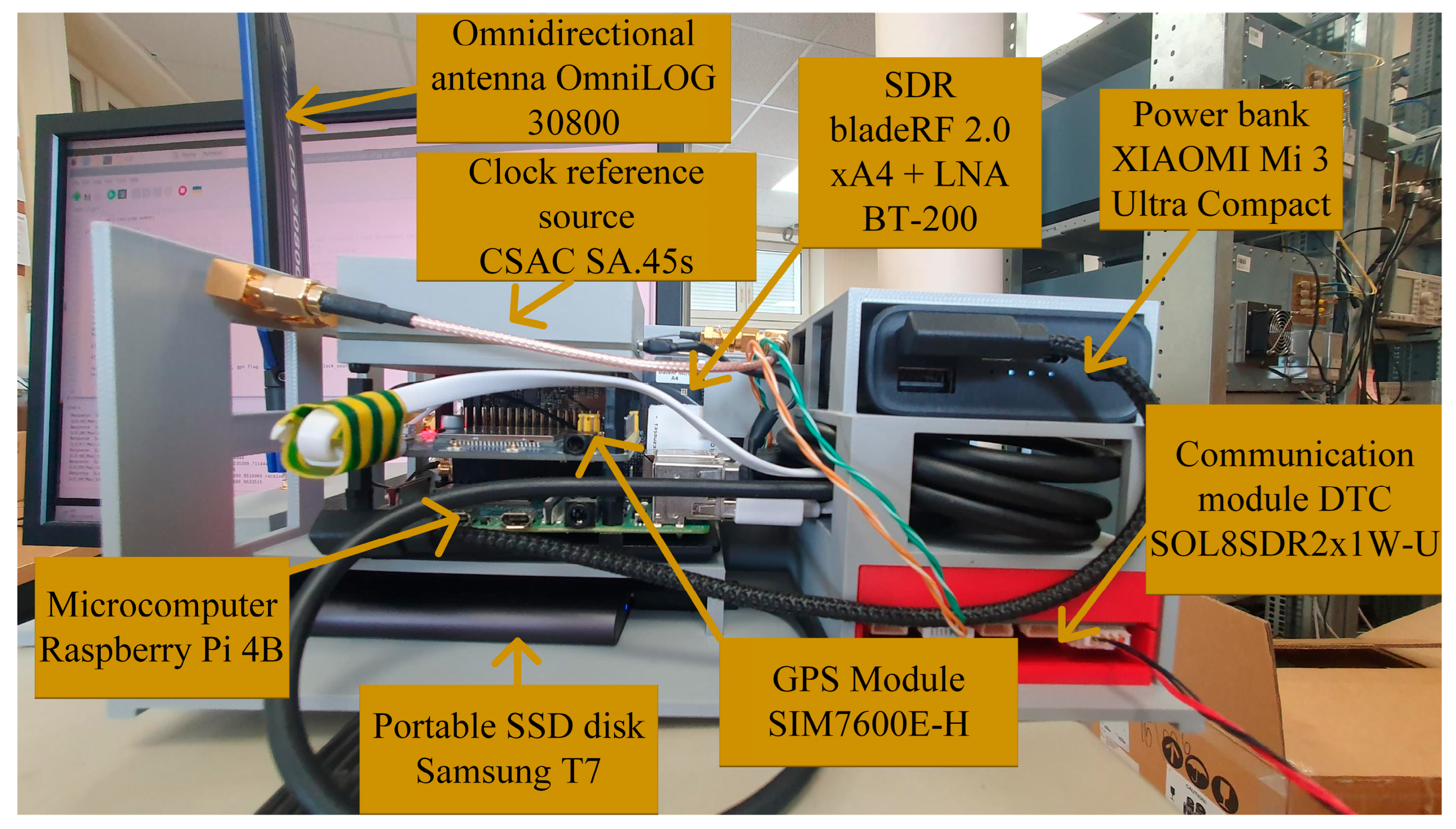
During the project, the system components changed their hardware and software structure many times. At first, they took the form of a stationary station set-up on a laboratory table. During the research and development of the sensors, efforts were made to minimize the elements so that they could ultimately be placed on a UAV. The current DLS implementation variant is shown in Figure 2.
It consists of:
  • Raspberry Pi 4B [23]—a microcomputer used to control the sensor and signal processing; the device consists of a single printed circuit board, Broadcom BCM2711 quad-core Cortex-A72 (ARM v8) 64-bit system on a chip (SoC) @ 1.8 GHz processor, 8 GB read access memory (RAM), two Universal Serial Bus (USB) 2.0 ports, two USB 3.0 ports, a Gigabit Ethernet interface, two Micro-High-Definition Multimedia Interface (Micro-HDMI) ports, a USB-C power connector, and General-Purpose Input/Output (GPIO) ports; the selected model has 8 GB RAM, which allows for dynamic allocation of the received signal and then saving it to static memory on a micro secure digital (microSD) card or external drive;
  • bladeRF 2.0 xA4 [24,25]—an SDR used to receive radio signals from localized emitters and transmit them to a microcomputer; bladeRF is a modern generation of SDR, offering a frequency range of 47 MHz to 6 GHz or 70 MHz to 6 GHz for transmitting and receiving, respectively; the maximum bandwidth is 56 MHz; housed in a small form factor, the bladeRF 2.0 micro is designed for high performance and mobile applications; the SDR can be used optional with low noise amplifier (LNA) BT-200 [26] allows for a significantly lower noise figure and increased dynamic range in most applications;
  • SA.45s [27]—a chip-scale atomic clock (CSAC) used to increase the stability and accuracy of frequency recovering; SA.45s is the specific CSAC solution available on the market; its small size, light weight, and energy efficiency make it perfect for designs, where minimizing size and power consumption are crucial; it is the only atomic clock that does not use the thermal stabilization technique;
  • XIAOMI MI 3 Ultra Compact [28]—a power bank used to power DLS components during testing; ultimately, the systems will be powered from the UAV’s onboard power supply; the used model is an extremely compact and efficient solution with a capacity of 10 Ah, which allows for powering the sensor systems for about 300 min;
  • SIM7600E-H [29]—a global navigation satellite system (GNSS) module used to determine a current DLS position during testing independently from the UAV platform; this module is dedicated for use with Raspberry Pi 4B and supports different GNSSs, i.e., GPS, GLONASS, BeiDou Navigation Satellite System (BDS), and location-based service (LBS); finally, the actual DLS coordinates will be provided by UAV telemetry;
  • Samsung T7 [30]—a portable solid-state drive (SSD) used to fast record in-phase and quadrature (IQ) components of complex samples and store the history of calculation results; its capacity is 2 TB, and the recording speed is up to 1000 MB/s; additionally, it is extremely compact and durable, which is important when used on a UAV;
  • OmniLOG 30800 [31]—wideband (i.e., operating in the range from 300 MHz to 8 GHz) omnidirectional antenna of small dimensions (173 mm × 63 mm × 9 mm) and weight (54 g); it has a standard SubMiniature version A (SMA) connector, is characterized by an impedance of 50 Ω and a gain of −3 dBi;
  • DTC SOL8SDR2x1W-U [32]—communication module used to control DLS elements in real time and send results to the C2S; it is an advanced solution, designed specifically for integration in unmanned systems; the device, depending on the version, can operate in the frequency sub-ranges of 1.2–1.7 GHz, 1.78–2.29 GHz, 1.98–2.7 GHz, or 4.4–5 GHz with a bandwidth of 1.25–20 MHz; the module supports various types of phase-shift keying (PSK) and quadrature amplitude modulation (QAM), such as binary PSK (BPSK), quadrature PSK (QPSK), 16-QAM, or 64-QAM; the device offers an output power of 2 W (i.e., up to 1 W for each channel); the manufacturer declares the Rx sensitivity at −110 dBm; it is characterized by high flexibility thanks to the number of connectors: Ethernet, USB-C, Recommended Standard 232 (RS232) [33], and low power consumption (7 W in Internet Protocol (IP) mesh mode); the transmission can be secured using Advanced Encryption Standard (AES)128/256; at this stage, the module has not been fully integrated with the rest of the DLS—we plan to do it only on the target UAV platform.
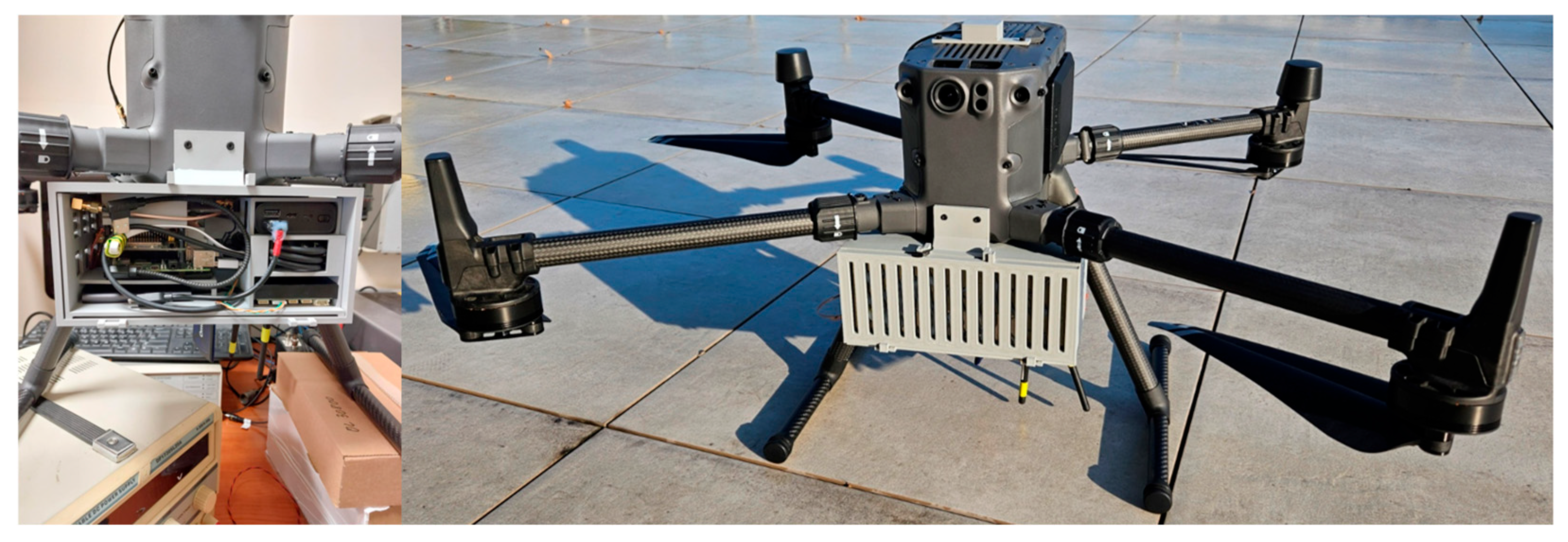
Figure 3 illustrates the DLS mounted on a Da-Jiang Innovations (DJI) Matrice 300 quadcopter with real-time kinematic (RTK) option. Finally, we plan to use a fixed-wing platform for the DLS, which can fly at a maximum speed of 120 km/h. A higher speed of a UAV positively increases the variability range and accuracy of a measured DFS.
The SAS elements are almost identical to those of the DLS. The main difference is the lack of a GNSS module in the SAS, which is unnecessary. The measurement data is oriented to the DLS movement trajectory, and knowledge of the SAS position is unnecessary from the viewpoint of the system’s operation. That is why it was decided not to mount the GNSS module on the SAS, which positively affects the weight and size of the transported load.
In the presented sensor configuration, all calculations are performed on a Raspberry Pi 4B. So, we are dealing with edge computing. Consequently, there is no need to transmit very large raw signal samples, but only the frequency estimation result with the necessary labels is transmitted. For the scenarios presented later in this paper, the modules operate in real time, and results are obtained in one-second intervals.
Currently, the only element limiting the real-time operation of the entire system is the lack of full integration of the radio module, which comes from the target UAV platform. However, it has been tested in laboratory conditions, where it allowed for integrated system operation. According to the system concept depicted in Figure 1, the DLS is to be placed on a wing-type UAV equipped with a target radio module. It will then be possible to conduct final tests of the effectiveness of the proposed edge computing solution.

3. Laboratory Tests of Doppler Localization Sensor

Initial DLS tests were conducted in laboratory conditions. They were based on the Doppler effect emulation in an acoustic signal. To initially assess the accuracy of the SDF method implemented in the DLS, we decided to emulate a spatial scenario (i.e., related to the Tx localization and Rx motion trajectory) similar to that planned for the empirical studies (see Section 4.2).

3.1. Idea of Doppler Effect Emulation by Acoustic Signal

Assuming that the location sensor works within the system presented in Section 2, it is possible in laboratory conditions to emulate phenomena occurring in the real environment. It aims to evaluate the possibility of locating a specific emitter, in our case, the AN/PRC-152A tactical radio. The emulation test allowed for a preliminary accuracy assessment of the SDF localization method implemented in the DLS. Such a test was conducted in laboratory conditions emulating the Doppler effect in an acoustic signal [12].
The AN/PRC-152A has many operating modes. We considered only the very-high frequency (VHF)/ultra-high frequency (UHF) line-of-sight (VULOS) waveform, which can be used with amplitude modulation (AM). In this case, radio can operate at the frequency range from 90 MHz to 512 MHz.
In the case of a sinusoidal message m ( t ) = A m sin ( 2 π f m t ) and carrier wave c ( t ) = A c sin ( 2 π f c t ) , an AM signal has the form [34]:
s ( t ) = A c sin ( 2 π f c t ) + k a A c A m 2 sin ( 2 π ( f c + f m ) t ) + k a A c A m 2 sin ( 2 π ( f c f m ) t ) ,
where k a is a positive constant parameter called the amplitude sensitivity of the modulator, A m and A c are amplitudes of the sinusoidal message and carrier wave, respectively, f m and f c are frequencies of the sinusoidal message and carrier wave, respectively.
The first term is a sinusoid at the carrier frequency f c , and it carries no message information. The other two terms are called sidebands (i.e., upper and lower sidebands, respectively) and carry the information in m ( t ) .
If we additionally consider the Doppler effect, the AM signal changes as follows:
s D ( t ) = A c sin ( 2 π ( f c + f D ) t ) + k a A c A m 2 sin ( 2 π ( f c + ( f m + f D ) ) t ) + k a A c A m 2 sin ( 2 π ( f c ( f m f D ) ) t ) ,
where f D is a DFS. In general, DFS may change over time.
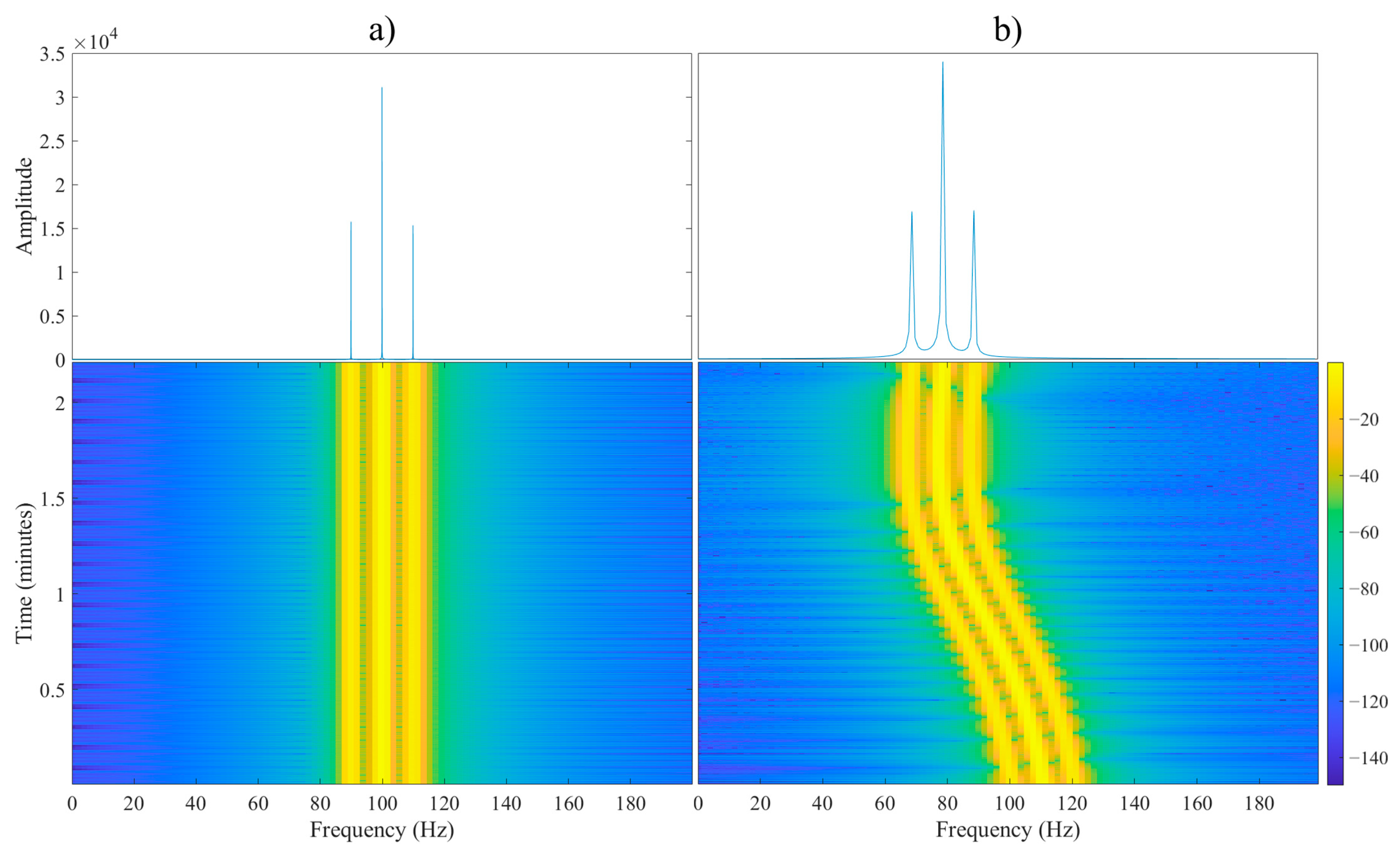
The signals received by the sensors moved to the baseband would look like in Figure 4 [12]. The instantaneous frequency f x ( t ) of the received signal would be determined using the spectral method, as the argument corresponding to the maximum of the signal spectrum. It can be noticed that the spectrum of the signal received by the fixed sensor (see Figure 4a) almost does not change over time, while the spectrum obtained for the moving sensor (see Figure 4b) is affected by the Doppler effect. For this reason, by subtracting the frequencies of the received signals in accordance with Equation (1), we obtain the DFSs. Based on them, we carry out localization procedures.
If we consider the Doppler effect in the modulating signal, i.e., when the form of the modulating signal is m ( t ) = A m sin ( 2 π ( f m + f D ) t ) , then the AM signal has the following form:
s ˜ ( t ) = A c sin ( 2 π ( f c ) t ) + k a A c A m 2 sin ( 2 π ( f c + ( f m + f D ) ) t ) + k a A c A m 2 sin ( 2 π ( f c ( f m + f D ) ) t ) .
We can see that the upper sideband in the AM signal with the Doppler effect s D ( t ) and the s ˜ ( t ) signal have the same form. We used this property to emulate the Doppler effect using a modulating signal. In emulation studies, we use an acoustic signal as a modulating signal, that has the form:
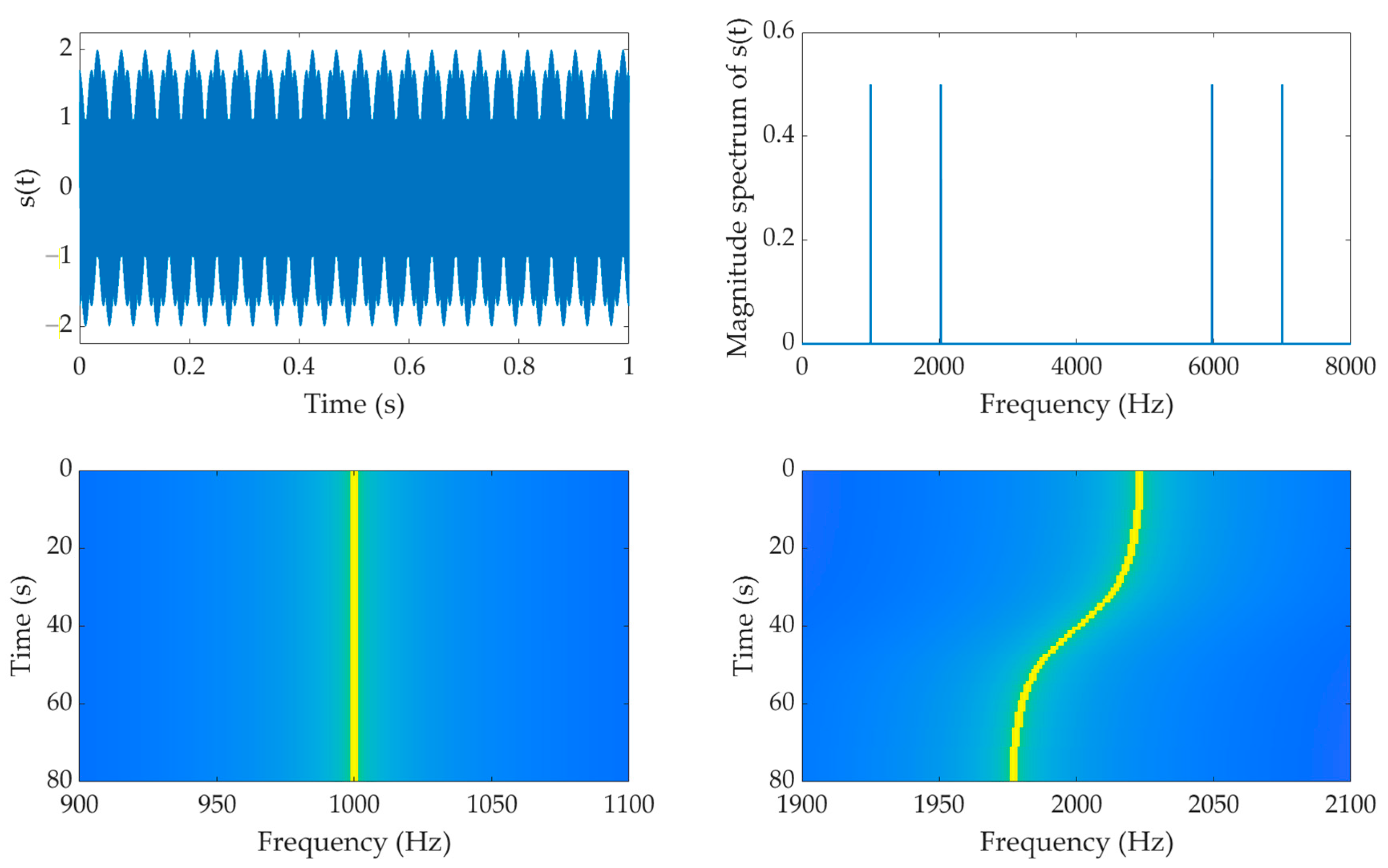
m D ( t ) = sin ( 2 π f 1 t ) + sin ( 2 π ( f 2 + f D ( t ) ) t ) ,
where f 1 = 1   kHz , f 2 = 2   kHz , and f D ( t ) is the DFS based on Equation (1).
The first component of the m D ( t ) signal simulates a stationary sensor. It is a single tone whose instantaneous frequency f x ( t ) is constant. The second component is responsible for emulating the Doppler effect. This method of modulating the acoustic signal allows us to emulate the Doppler effect in laboratory conditions, considering various operational scenarios. An exemplary structure of a signal prepared in this way (consisting of two tones, i.e., fixed and time-varying) is shown in Figure 5 [12].
The emitting of the m D ( t ) signal using the tested emitter allows for assessing the possibility of its location by the SDF. The frequency oscillations of the received signal generated by the examined Tx should be close to those obtained in real conditions.

3.2. Emulation Test-Bed

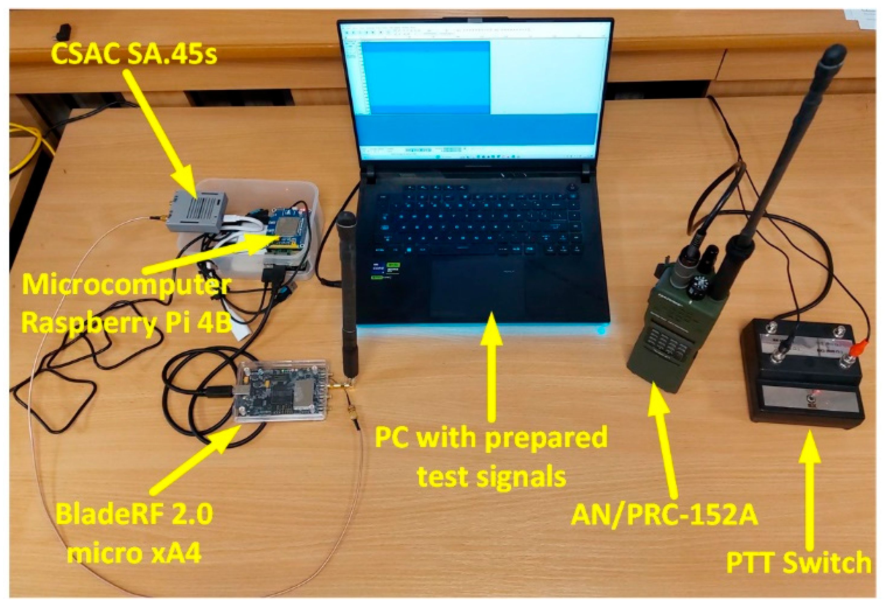
The test-bed to emulate the Doppler effect by an acoustic signal and measure this phenomenon to assess the possibility of locating the tested radio consists of a transmitting and receiving part, which are depicted in Figure 6 [12].
The transmitting part includes the tested AN/PRC-152A tactical radio with an attached push-to-talk (PTT) switch, allowing continuous signal transmission without needing to hold the PTT button on the radio. The PTT switch also has the function of feeding an audio signal to the radio. In this case, the prepared audio signal consisting of the two tones discussed in the previous section is fed from the laptop through a jack plug.
The emitted signal is received by the location sensor, i.e., the receiving part of the laboratory test-bed. In this case, the sensor elements include [12]:
  • bladeRF 2.0 micro xA4 as an SDR platform with an antenna designed for the required frequency range, responsible for receiving the signal;
  • Raspberry Pi 4B microcomputer connected to the SDR platform, responsible for its control, as well as acquisition and processing of the received signal;
  • CSAC SA.45s atomic clock, whose 10 MHz reference signal is fed to the SDR;
  • power supply—in laboratory conditions, the microcomputer is supplied via a dedicated Raspberry Pi power supply, and the CSAC is powered by an independent battery.

3.3. Emulation Scenario

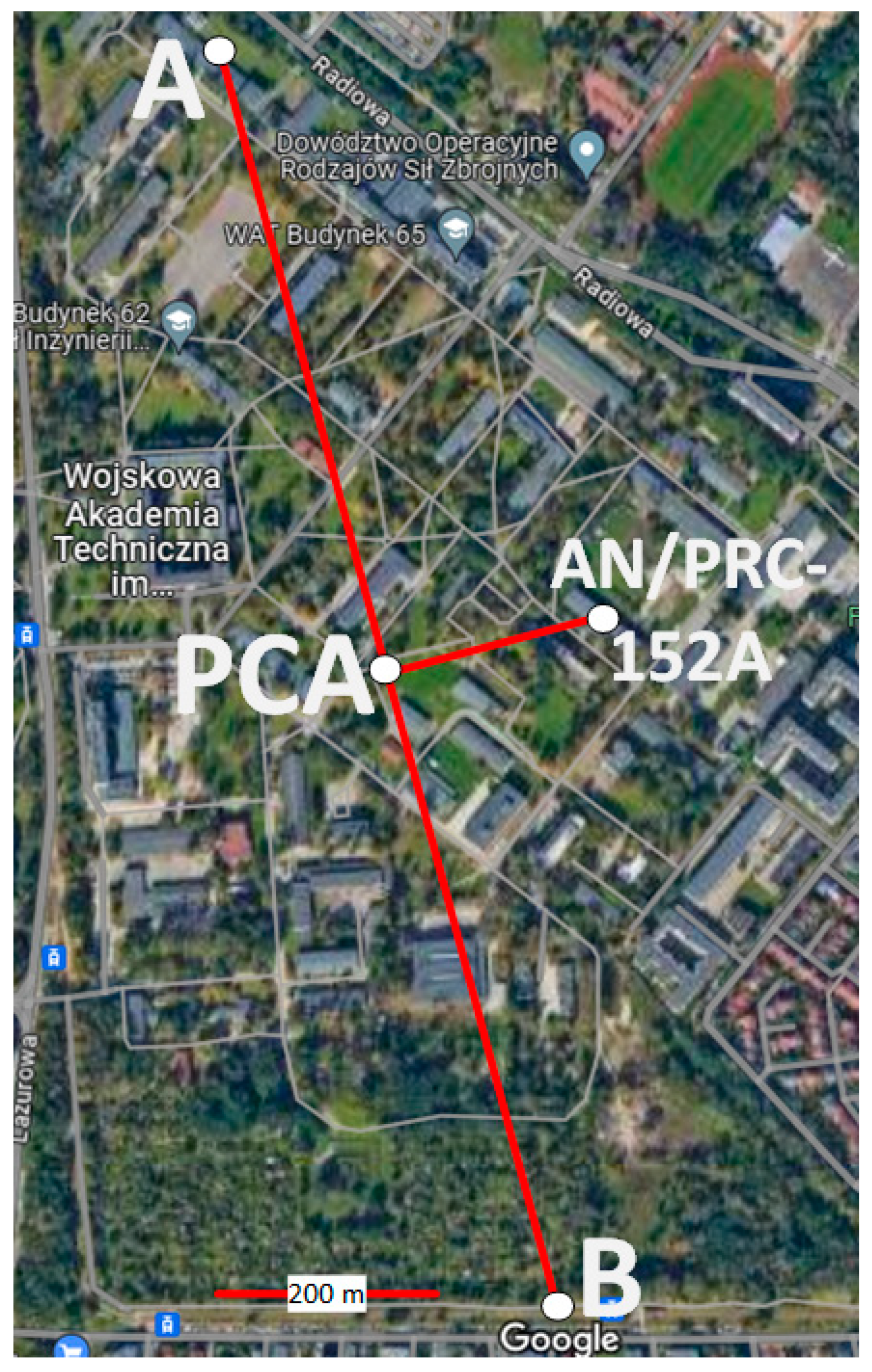
The research scenario assumed that the UAV with the installed DLS moves along the line connecting points A and B, shown in Figure 7. The length of the UAV route connecting points A and B is 1200 m. After 600 m, the UAV is at a point of closest approach (PCA) [10]. The distance between the PCA and the located AN/PRC-152A tactical radio is 200 m.
The presented spatial scenario was used for three carrier frequencies of the transmitted signal f c set to AN/PRC-152A, i.e., 125, 250, and 500 MHz. Two flights were made for each carrier frequency f c to average the location error.
In the emulation studies, the following additional assumptions were made [12]:
  • sensor (i.e., DLS/Rx) moves on a UAV with constant speed v = 15   m / s , at a constant altitude h = 100   m above the flat land, along a straight trajectory with a length of S = 1.2   km
  • origin of the local coordinate system OXYZ is located at point A (i.e., the beginning of the Rx path), and the OX axis is oriented along the AB segment (i.e., related to the direction of the Rx movement);
  • emitter (i.e., Tx) position relative to the local coordinate system OXYZ is x 0 , y 0 , z 0 = 600 , 200 , 100 m ;
  • sensor performs 2D localization in the OXY plane (i.e., the Rx flight at a constant altitude and the z coordinate is known, z z 0 = h );
  • location sensor estimates the instantaneous frequency f x ( t )  every 1 s;
  • acquisition time t A  of the received signal is equal to 30 s, which means the coordinates of the AN/PRC-152A are estimated every 1 s based on 30 DSFs;
  • tactical radio AN/PRC-152A conducts a continuous radio transmission lasting approximately 70 s;
  • test signals are prepared according to the procedure presented in Section 3.1.
The spatial scenario for the assumptions adopted by emulation studies is presented in Figure 7 [12].

3.4. Emulation Result Analysis

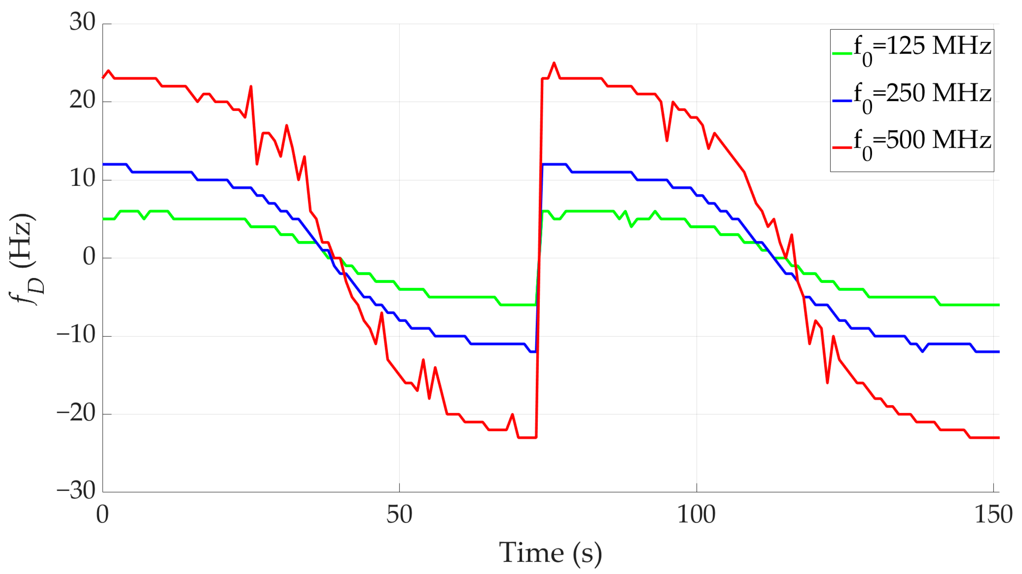
Based on Equation (1) and the obtained frequency curves versus time, f x ( t ) and f 0 ( t ) , we determined the Doppler curves shown in Figure 8. Next, by substituting the obtained DFSs into Equations (2) and (3), the coordinates x ( t ) and y ( t ) of the tactical radio are determined. The localization error is calculated according to
Δ r ( t ) = ( x ( t ) x 0 ) 2 + ( y ( t ) y 0 ) 2 ,
where x 0 , y 0 and x ( t ) , y ( t ) are the actual and estimated emitter (i.e., Tx) position relative to the sensor (i.e., Rx).
According to the scenario assumptions, the flight is performed twice, which is presented with two Doppler curves in Figure 8. The estimation of the Tx coordinates and the determination of the location error were also performed twice. The error obtained for two repetitions was averaged based on the following formula
Δ r ¯ ( t ) = 1 K k = 1 K Δ r k ( t ) ,
where K = 2 and Δ r k ( t ) is a location error defined by Equation (9) for the kth execution of a scenario.
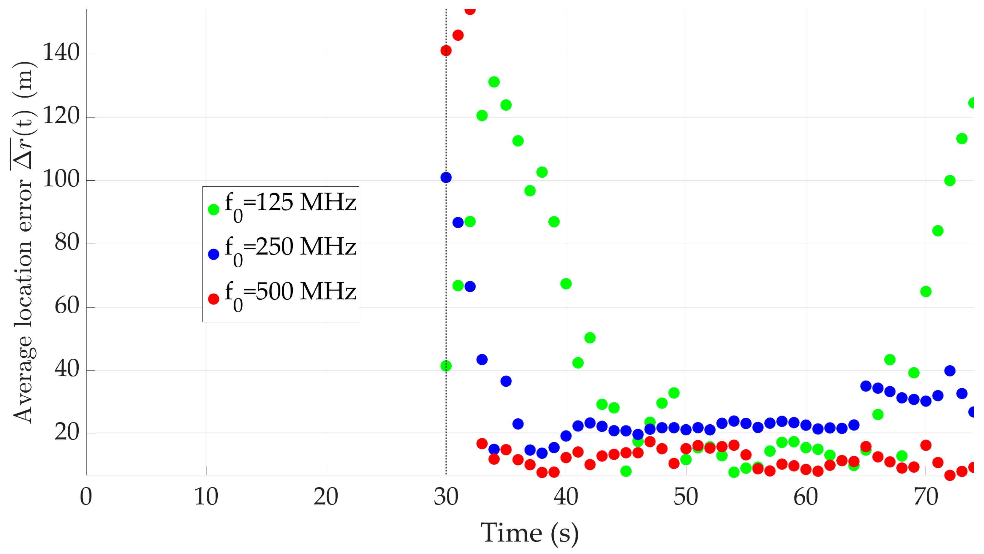
The obtained average location error is presented in Figure 9 and Table 2. The table also contains the mean value μ Δ r ¯ and standard deviation σ Δ r ¯ of the obtained average location errors Δ r ¯ ( t ) for each tested carrier frequency f 0 defined as follows:
μ Δ r ¯ = E { Δ r ¯ ( t ) } ,
σ Δ r ¯ = E { ( Δ r ¯ ( t ) μ Δ r ¯ ) 2 } ,
where E { } is the expectation operator.
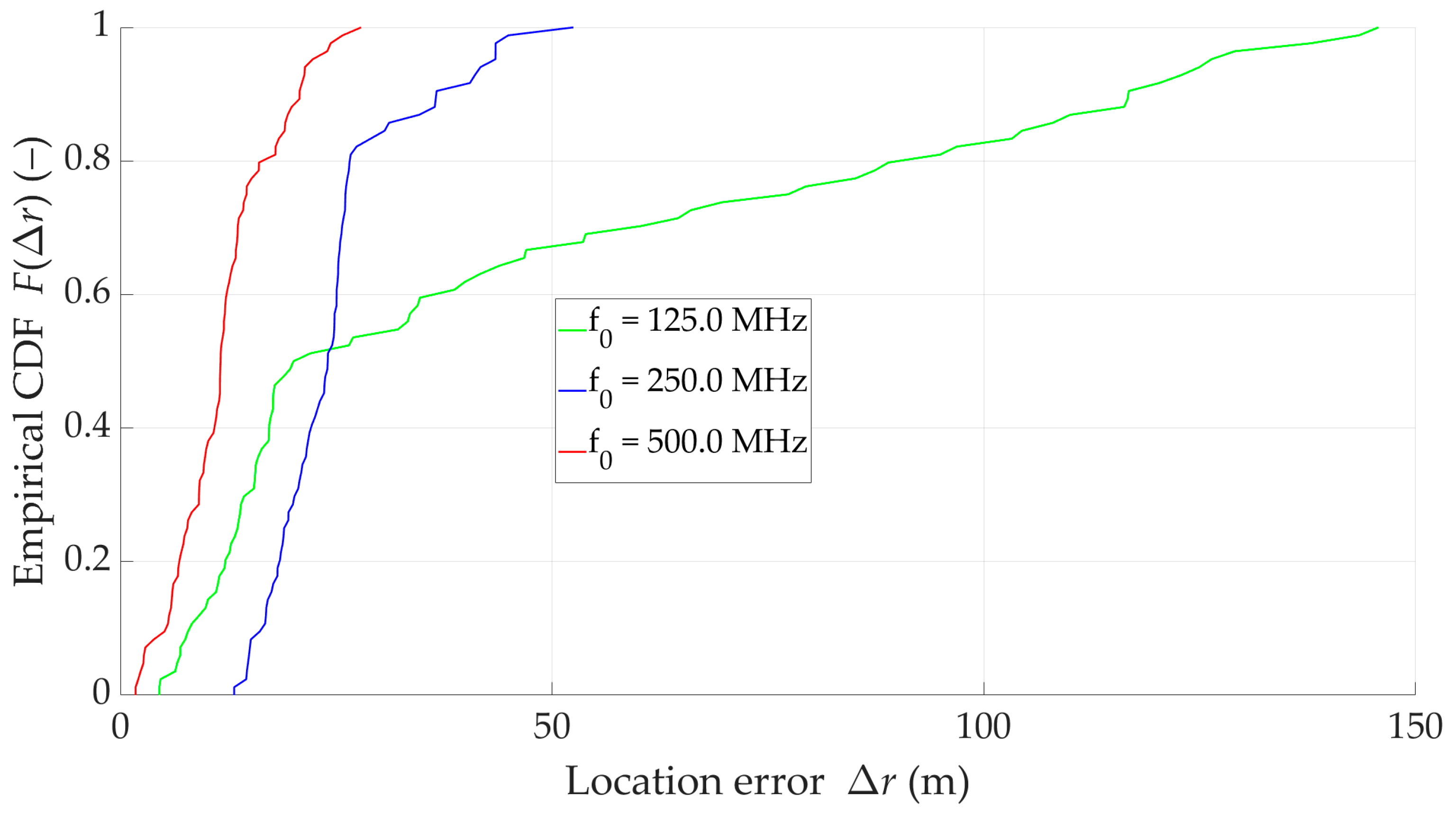
The lack of a characteristic trend in location error changes versus carrier frequency in Table 2 complicates interpreting the results. These difficulties result from anomalous errors occurring for analysis times of 30–32 s (see Figure 9), which cause, i.a., a significant error spread (i.e., σ Δ r ¯ ) for f 0 = 500   MHz . Omitting these values in further analysis allows for clear conclusions to be drawn. Table 3 presents the analyzed error metrics for t > 32   s . The empirical cumulative distribution functions (CDFs) of localization errors for laboratory tests conducted at three carrier frequencies of the emitted signal are also determined for such a limited analysis time. These CDFs are presented in Figure 10.
As the carrier frequency increases, we observe a monotonic increase in the mean value μ Δ r ¯ , standard deviation σ Δ r ¯ , and maximum value of the localization error. Only for f 0 = 250   MHz , the minimum error takes on a larger value relative to the two other analyzed carrier frequencies. In practice, the minimum error is usually not analyzed.
The obtained results show that the localization of signal sources emitting higher frequencies is more accurate. This is related to the greater dynamics of DFS. Measured DFSs are generally subject to similar absolute errors regardless of their dynamics. Therefore, at higher carrier frequencies of the received signal, the instantaneous DFSs have smaller errors, and finally, the location accuracy for the SDF method is better.
We assumed that all emulation tests correspond to LOS conditions, so the impact of multipath propagation is minimized. Under non-LOS (NLOS) conditions, multipath propagation makes it difficult to determine the instantaneous value of the received signal corresponding to the emitter’s carrier frequency. In this case, a Doppler spread spectrum is obtained instead of the Doppler spread spectrum characteristic for a given Tx-Rx spatial configuration.
Another important requirement of the SDF method is that the received signal must be detectable above the noise floor. If the received signal cannot be distinguished from noise, the method cannot extract reliable DFS, making localization impossible. This highlights the importance of ensuring a sufficient SNR for the applicability of the method.
Although the results indicate superior accuracy for higher carrier frequencies, it should be noted that propagation losses increase with frequency. In practice, this introduces a trade-off between the benefits of larger DFS dynamics and the challenges of ensuring adequate SNR at higher frequencies, especially over longer distances. Therefore, the effectiveness of the SDF method depends on both the carrier frequency and the specific propagation environment.

4. Empirical Studies of Doppler Localization Sensor

4.1. Measurement Test-Bed

The test-bed for conducting the localization capabilities of the tactical radio in an empirical environment consisted of two parts: a transmitting and receiving one. The receiving part included the SAS and DLS mounted on UAVs DJI Matrice 300 RTK discussed in Section 2.4.
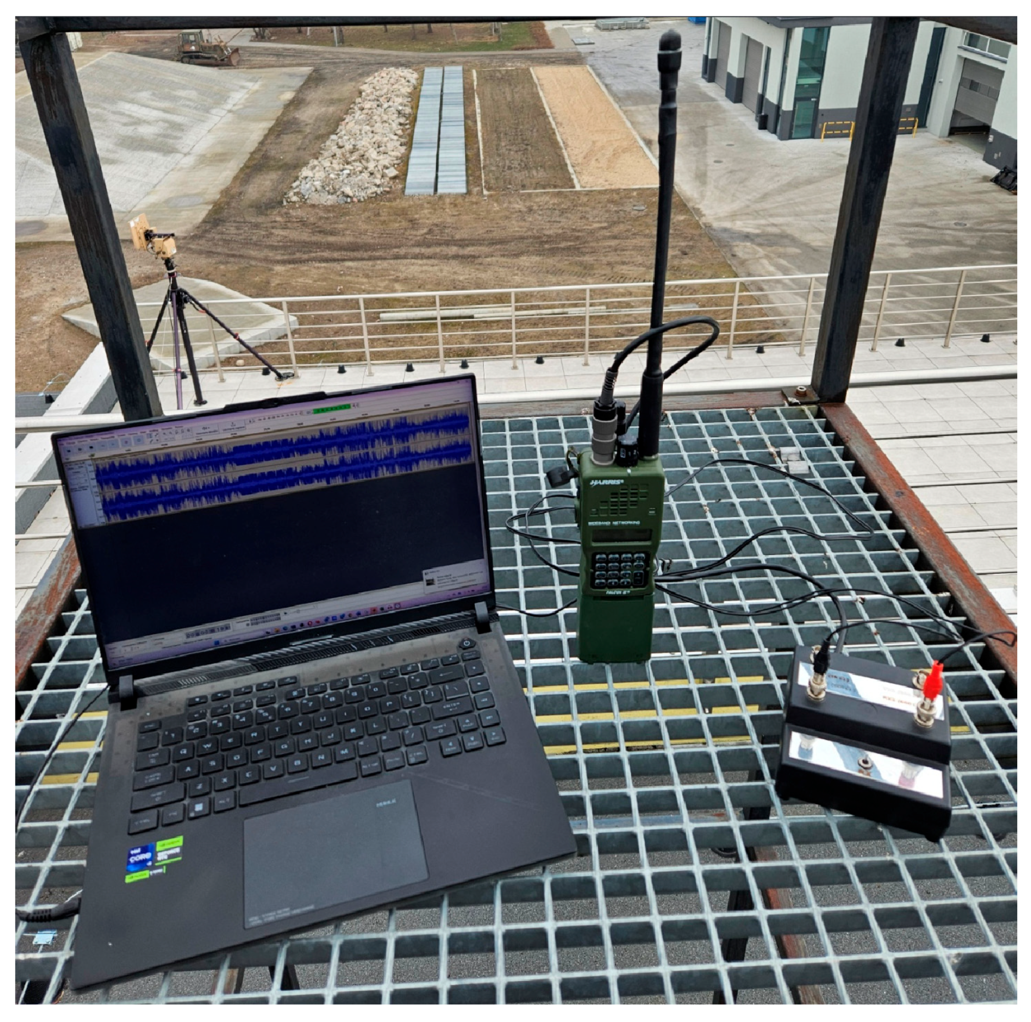
The transmitting part of the test-bed is depicted in Figure 11. It consisted of the AN/PRC-152A tactical radio and a PTT switch discussed in Section 3.2. The PTT switch allowed continuous transmission without holding a button on the radio. Additionally, using the PTT switch, an audio signal containing human speech is also supplied to the radio’s audio input from the computer. Five different AN/PRC-152A radios were used for the test. This part of the test-bed was placed on the roof of the building to ensure direct visibility of the antennas (i.e., LOS conditions between Tx and Rx). This radio can set the transmitting power level. During the tests, the medium level of 2 W was set. During the studies, the VULOS waveform and AM modulation were used.

4.2. Measurement Scenario

During the empirical tests, the UAV carrying the SAS was raised to a height of h = 100   m and hovered while the DLS flew along the route between points A and B (see Figure 7). Therefore, empirical tests were performed for the spatial scenario adopted in the laboratory tests described in Section 3.3. In addition, the following assumptions were made in the scenario:
  • UAV with the DLS flight velocity is set to v = 15   m / s ;
  • AN/PRC-152A conducts a continuous radio transmission with the signal modulated AM on the tested carrier frequency f 0 ;
  • mounting height of the transmitting antenna (tactical radio) is equal to h A = 15   m ;
  • test is performed for two carrier frequencies f 0 = { 350.8 ,   869.0 }   MHz  set on the tactical radio;
  • receiving frequency set on DLS/SAS is equal f R X = f 0 10   kHz ;
  • radio output power was 1W;
  • five copies of the AN/PRC-152A radios were used for the study;
  • for each radio and each carrier frequency f 0 , four passes were made along the route shown in Figure 7, which gives forty results (i.e., the Doppler curves);
  • the analyzed signal bandwidth is set to B = 524.288   kHz ;
  • every 1 s, DLS and SAS estimate the instantaneous frequency f x ( t ) or carrier frequency f 0 ( t ) , respectively;
  • acquisition time t A  of the received signal is equal to 10 s that means the emitter (i.e., AN/PRC-152A) coordinates are estimated every 1 s based on 10 DFSs.
It is worth mentioning that the differences in carrier frequency f 0 selection between the emulation and empirical studies unfortunately result from the time that elapsed between them. At the time of the empirical studies, we lost our permit to broadcast on the frequencies used in the emulation studies. Therefore, we used similar values, for which we had permission at the time of the empirical studies.

4.3. Result Analysis

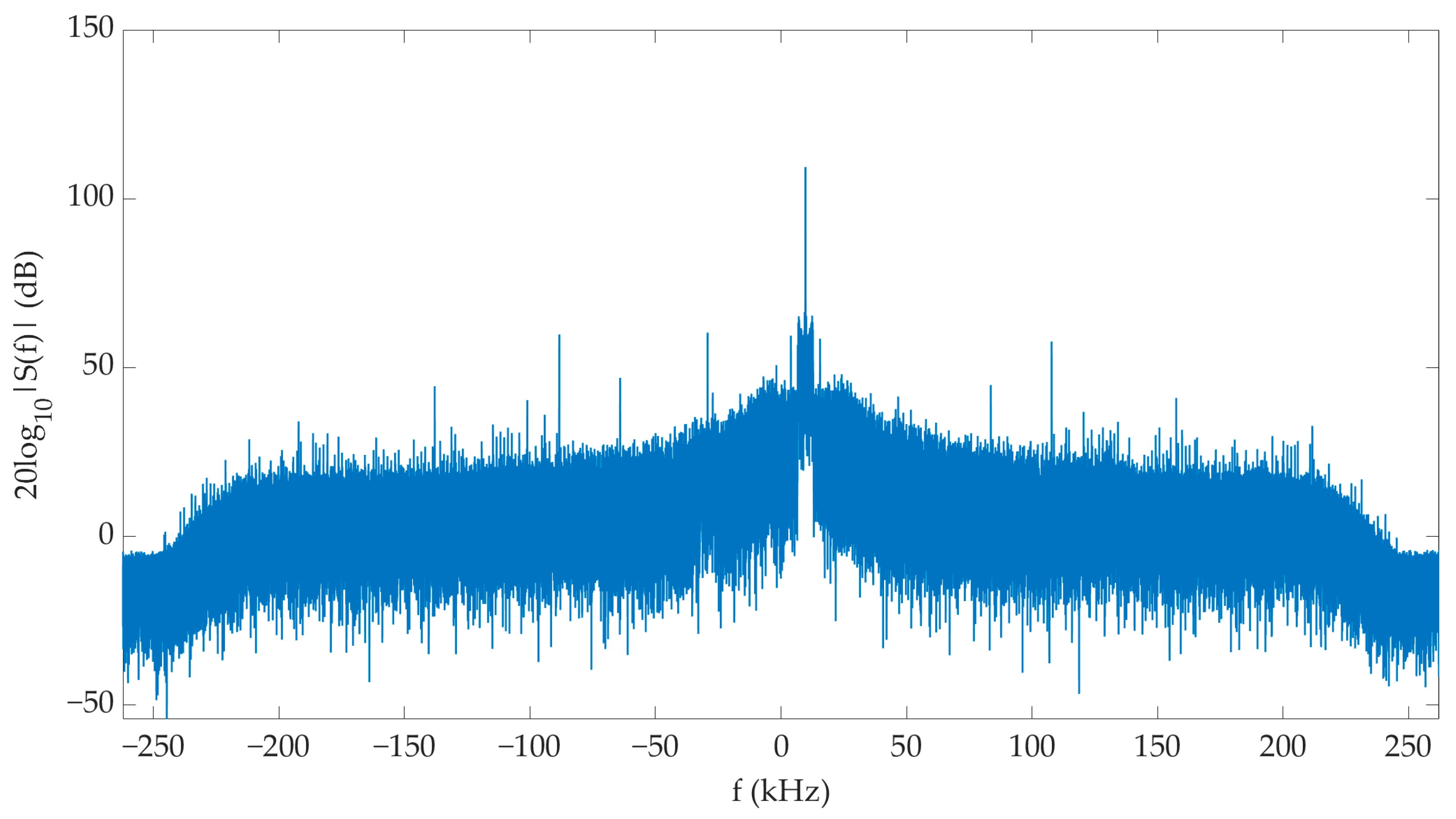
Using the test-bed presented in Section 4.1 and additional assumptions discussed in Section 4.2, a study was conducted to verify the ability of the designed UAV reconnaissance system to localize the AN/PRC-152A tactical radio. An example spectrum of the signal recorded during the measurements in the entire signal bandwidth B analyzed by the DLS is illustrated in Figure 12. The presented spectra of the received signal indicate an adequate SNR enabling DFS estimation.
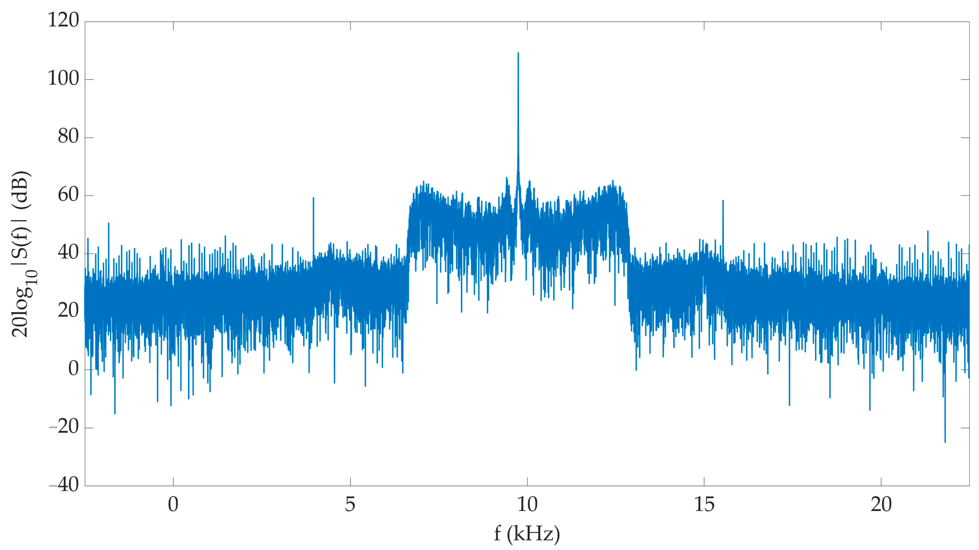
AN/PRC-152A is operating in the VULOS waveform with AM and a 25 kHz channel. For this reason, only this spectrum fragment is presented in Figure 13. In this case, we can see characteristic elements for double-sideband modulation with a carrier wave, such as symmetry with respect to the full carrier wave. Characteristic spectrum components greatly facilitate the estimation of the DFS.
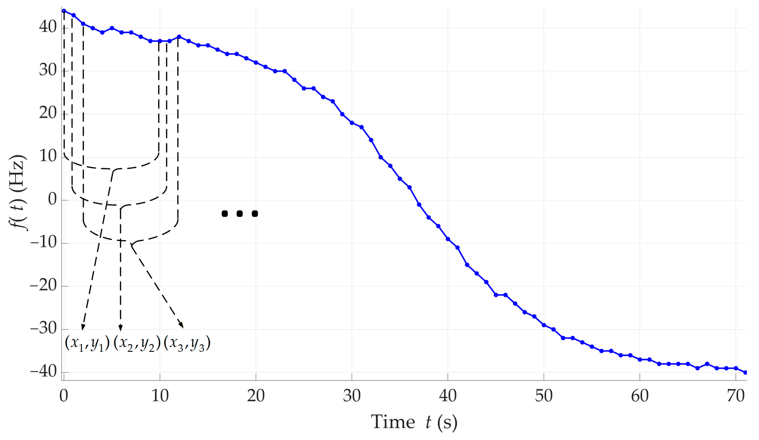
Using spectral analysis, the characteristic frequencies f 0 ( t ) and f x ( t ) of the signals received by the SAS and DLS, respectively, for subsequent time intervals were estimated. Example curves of the instantaneous frequencies f x ( t ) , f 0 ( t ) , and f D ( t ) calculated based on Equation (1) are shown in Figure 14. Here, we observe frequency graphs determined in the baseband. These results were obtained for the test performed at the carrier frequency 869 MHz. They represent the data obtained for a four-time flight along the route declared in the measurement scenario. In this case, it can be seen that the use of two sensors (i.e., DLS and SAS) is justified due to the time-varying values of f 0 ( t ) and f x ( t ) . During four passes lasting about 400 s, the carrier frequency f 0 ( t ) changed its value by about 10 Hz. Therefore, assuming its constant value when calculating the Tx position coordinates, we would burden the results with significant errors.
The Doppler curves obtained during empirical trials indicate that LOS or obscured LOS (OLOS) conditions were ensured for the analyzed flight trajectory of the UAV-DLS (Rx) relative to the localized object (Tx). Therefore, the LOS assumption for the analyzed spatial scenario (see Figure 7) adopted during the emulation tests was correct. On the other hand, these results show that using aerial platforms for implementing SDF or other Doppler-based methods has advantages over ground-based platforms. Flight of the sensor at relatively low altitudes usually ensures LOS/OLOS conditions.
For a given UAV flight along the assumed route (see Figure 7), the Tx coordinates were determined based on Equations (2) and (3). We average the results in the acquisition window t A = 10   s , so the single coordinates ( x , y ) were determined every 1 s based on the ten most recently measured DFSs. Then, the analysis window was shifted by one DFS and the Tx position were calculated again, as shown in Figure 15. The use of windowing, discussed in more detail in [10], allowed obtaining up to sixty localization results for a single Doppler curve.
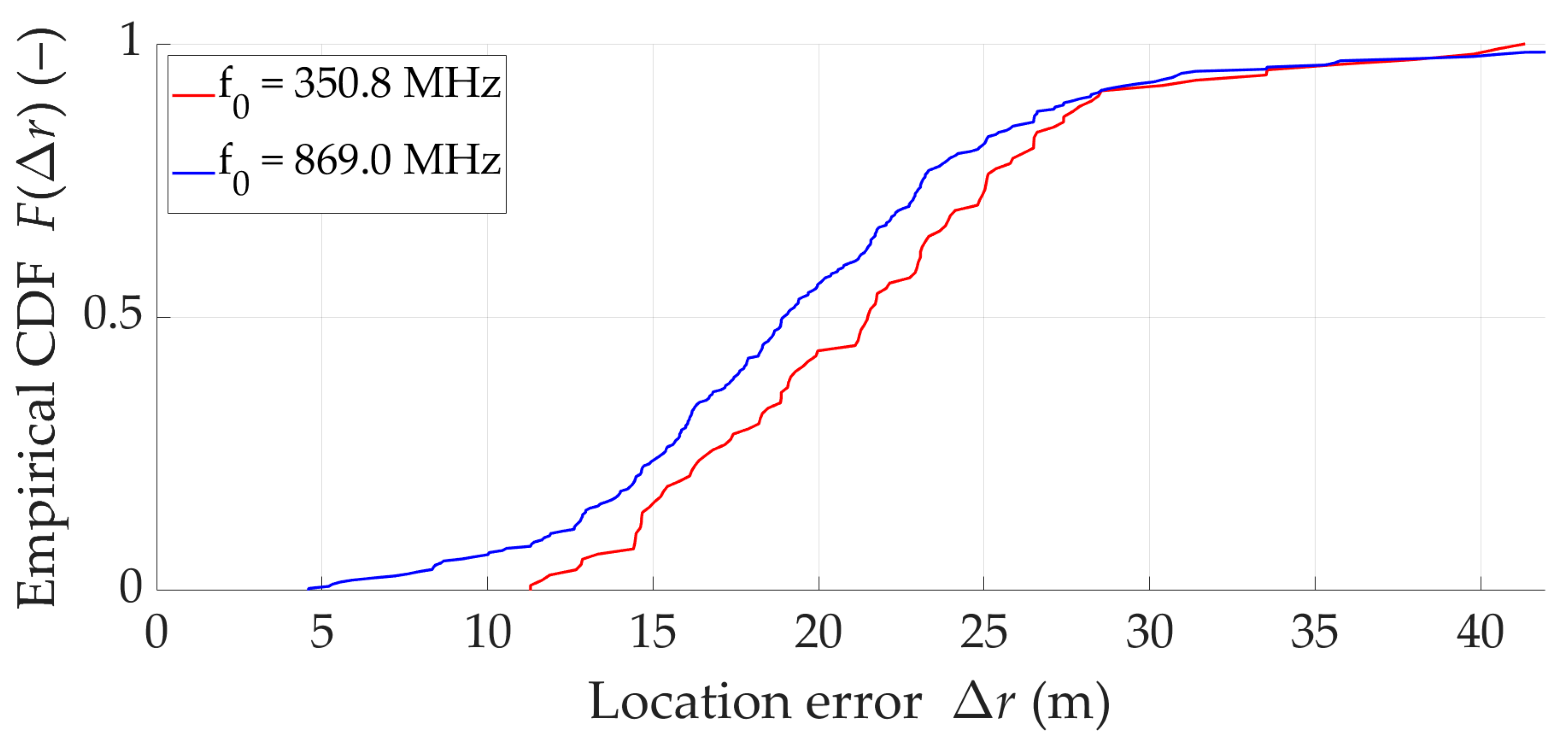
The localization errors are calculated based on Equations (9)–(12) and presented in Table 4. Figure 16 depicts empirical CDFs of location errors for two analyzed carrier frequencies. CDFs were averaged for all copies of the tactical radios.
The average localization error in the empirical studies is 13–23 m, and its average spread (i.e., deviation) is about 7 m, and only in one case did it exceed 8.3 m. We can conclude, that these are very good results considering the UAV-DLS flight route length of 1200 m and the PCA distance to the route of 200 m.
It is worth emphasizing that the localized target was the tactical radio (i.e., AN/PRC-152A), which is not characterized by such good frequency stability as, e.g., signal generators used in the laboratory. This factor (i.e., the frequency stability of the Tx clock) [13] has a significant impact on localization accuracy based on frequency methods (including the SDF), as drawn in [13]. Analyzing the obtained results in terms of the carrier frequency of the transmitted signal, it can be concluded that localization errors are similar or slightly smaller at approximately a two-and-a-half-fold increase in frequency. However, the CDFs show that the location error is statistically several meters smaller for higher frequencies.

5. Synthesis of Results

For empirical studies, the acquisition time t A was set at 10 s. Whereas, during laboratory tests, this parameter was assumed to be 30 s. These values were chosen empirically in previous studies. With proper implementation of the method, both acquisition time t A values should allow for effective emitter localization. A more detailed analysis of this parameter can be found in [36]. Additionally, tests were performed for different carrier frequencies of the transmitted signal. To compare empirical with emulation results, we perform additional calculations for other acquisition times based on the data recorded in the real environment. The summary of this analysis for the two tested carrier frequencies and three acquisition times is presented in Table 5.
The mean location error and its deviation increase with increasing acquisition time. For the analyzed parameter values, we obtained 20.1 ± 6.3–21.8 ± 8.5 m, 26.0 ± 14.7–28.3 ± 17.5 m, and 32.4 ± 26.5–37.1 ± 28.2 m for t A equal to 10, 20, and 30 s, respectively. Therefore, the choice of acquisition time has a significant impact on the SDF accuracy. In this case, a smaller value positively affects the reduction of localization error. As in previous analyses, the location of transmitters emitting a signal at a higher carrier frequency is more accurate. However, for frequencies of 350.8 and 869 MHz, these differences are on the order of a few meters.
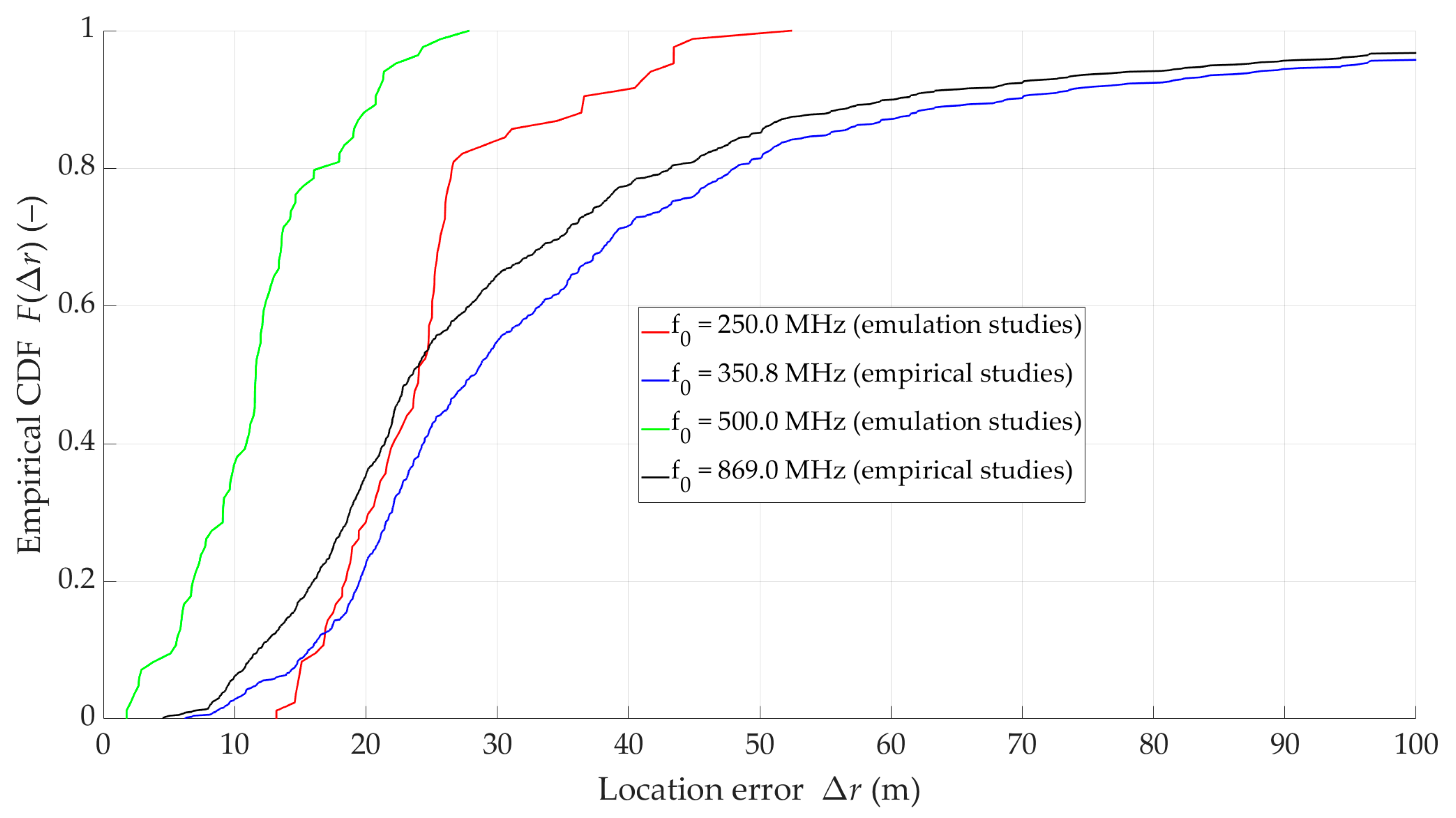
Figure 17 presents empirical CDFs of location error for four similar carrier frequencies, i.e., f 0 = { 250 , 500 } ( MHz ) and f 0 = { 350.8 , 869.0 } ( MHz ) in the laboratory and empirical studies, respectively. The acquisition time for all cases is set to 30 s. Additionally, the error metrics are summarized in Table 6.
The CDFs of location errors obtained for laboratory and empirical results show significant differences. Comparing the appropriate results for 250 with 350 MHz and 500 with 869 MHz, we can conclude that the average positioning errors obtained with Doppler effect emulation are approximately 23–35% lower than those obtained with empirical measurements. This general characteristic may be primarily due to the fact that the laboratory tests were conducted in a room with a stable temperature, i.e., the equipment was not exposed to solar radiation, which significantly affects the stability of the Tx/Rx clocks. Furthermore, UAV-DLS (Rx) motion modeling is implemented by loading theoretical frequency changes represented by the Doppler curve. In empirical studies, a natural characteristic of UAV motion is its speed change (i.e., its oscillation around a fixed mean speed), which translates into additional DFS oscillations resulting from the definition presented in Equation (2). It should also be remembered that the multipath propagation of a radio wave is an important factor influencing the shape of the spectrum of the received signal, and therefore the accuracy of the DFS estimation [11]. Considering these observations, emulating the Doppler effect should consider some randomness in the Doppler curve changes resulting from Rx motion, clock frequency instability, and multipath propagation (i.e., more complex modeling of the radio channel [11]).
On the other hand, we may observe some commonalities in the two studies. The general nature of the results, including the smaller positioning errors obtained for higher frequencies, indicates that both approaches are valid. The laboratory and empirical tests have demonstrated the high effectiveness of the proposed SDF-based solution. However, improving localization accuracy requires appropriate parameter selection and signal processing.
Comparing emulation results (red and green) with empirical findings (blue and black) shows that emulated data tend to produce more optimistic outcomes, possibly due to a more controlled or idealized radio environment. The discrepancy between emulation and empirical results is particularly notable at lower location errors, where multipath, interference, and other real-world factors can degrade performance. Both the emulation and empirical test results indicate the possibility of locating a tactical radio operating with AM modulation using the designed localization sensor. For all tested carrier frequencies, 80% of location errors Δ r do not exceed 50 m, which is a satisfactory result at a distance between the Tx and Rx of 200–632 m.

6. Conclusions

The paper presents a custom-built reconnaissance system using UAVs with RF sensors. These sensors (i.e., SMS, DLS, and SAS) are based on an SDR and a chip-scale atomic clock. One is designed to detect and localize real-world RF sources with limited frequency stability, such as the L3Harris AN/PRC-152A tactical radio. In the paper, we cover the theoretical foundations, system architecture, and the results of both laboratory emulation and real-world field tests.
This study demonstrated the feasibility and effectiveness of using a single UAV equipped with the Doppler-based SDR sensor (i.e., DLS) for localizing RF emitters, specifically modern tactical radios such as the L3Harris AN/PRC-152A. Using an additional UAV with the SDR sensor (i.e., SAS) reduces the unfavorable impact of frequency instability of the localized object. Unlike conventional systems relying on multiple UAVs or fixed infrastructure, the proposed method enables autonomous operation using only frequency shift measurements. Both emulation and empirical studies confirmed that the system is capable of achieving localization errors below 50 m in most cases, even when operating with real-world Txs characterized by limited frequency stability. The results also showed that factors such as carrier frequency and acquisition time significantly influence localization accuracy. By addressing the challenges associated with localizing non-cooperative, mobile, or analog-modulated emitters, this work contributes to the development of lightweight, deployable RF localization tools for use in spectrum monitoring, infrastructure protection, and defense applications. Despite a localization error of several dozen meters, the strength of the presented system and localization method lies in its rapid deployment and operation. It is suitable for applications where rapid response is essential, including SAR operations, pinpointing sources of unauthorized emissions in cities and protected zones (airports, ports, refineries), protecting critical infrastructure through patrol detection and localization of emissions near power lines and power plants, and in public safety applications, identifying sources of emissions disrupting communications between services, and supporting law enforcement operations during mass events.
Future research will focus on developing a modification of the SDF method aimed at minimizing the impact of changes in the UAV instantaneous speed on the accuracy of emitter location. This approach is expected to improve localization accuracy under realistic flight dynamics and broaden the applicability of the proposed method in scenarios such as SAR, rapid deployment, and reconnaissance missions where robustness and autonomy are prioritized. In the next step, we want to evaluate the impact of changes in other UAV flight parameters, including altitude fluctuations, flight trajectory nonlinearity, or GPS inaccuracies, on positioning accuracy.

Author Contributions

Conceptualization, J.W.; Data curation, K.B. and R.S.; Formal analysis, K.B., J.W. and R.S.; Funding acquisition, J.M.K.; Investigation, K.B. and R.S.; Methodology, J.W.; Project administration, J.M.K.; Resources, K.B. and R.S.; Software, K.B. and J.M.K.; Supervision, J.M.K.; Validation, J.W.; Visualization, K.B. and R.S.; Writing—original draft, K.B., J.W., R.S. and J.M.K.; Writing—review & editing, K.B., J.W., R.S. and J.M.K. All authors have read and agreed to the published version of the manuscript.

Funding

This work was developed within a framework of the research project on “Command and control of group of COMINT radio-electronic reconnaissance unmanned aerial vehicles based on modern IT technologies”, acronym UAV-COMINT, no. DOB-SZAFIR/01/B/029/03/2021, sponsored by the National Center for Research and Development (NCBR), Poland, under the 3/SZAFIR/2021 program, and grant no. UGB/22-059/2025/WAT sponsored by the Military University of Technology (WAT).

Data Availability Statement

Restrictions apply to the availability of these data. The dataset is available upon request from the authors.

DURC Statement

“UAV Equipped with SDR-based Doppler Localization Sensor for Positioning Tactical Radios” is limited to the field of unmanned aerial systems (UASs), RF signal processing, and radio emitter localization methods based on Doppler frequency measurements. This research is beneficial for civilian applications such as critical infrastructure protection, public safety, and spectrum management, and does not pose a threat to public health or national security. Although the research involves the use of a dual-use communication device (L3Harris AN/PRC-152A), the purpose of this work is scientific and technological in nature, with no intent to develop or enhance military capabilities. The authors acknowledge the dual-use potential of this research and confirm that all necessary precautions have been taken to prevent potential misuse. As part of their ethical responsibility, the authors strictly adhere to relevant national and international laws and regulations governing dual-use research of concern (DURC). The authors advocate for responsible deployment, ethical considerations, regulatory compliance, and transparent reporting to mitigate misuse risks and foster beneficial outcomes.

Acknowledgments

The authors would like to express their great appreciation to the Drones journal editors and anonymous reviewers for their valuable suggestions, which have improved the manuscript quality.

Conflicts of Interest

The authors declare no conflicts of interest.

Abbreviations

The following abbreviations are used in this manuscript:
2DTwo-Dimensional
3DThree-Dimensional
AESAdvanced Encryption Standard
AIArtificial Intelligence
AMAmplitude Modulation
AOAAngle Of Arrival
BDSBeiDou Navigation Satellite System
BPSKBinary Phase-Shift Keying
C2SCommand and Control Station
CDFCumulative Distribution Function
CSACChip Scale Atomic Clock
DFSDoppler Frequency Shift
DJIDa-Jiang Innovations
DLSDoppler Localization Sensor
DPDDirect Position Determination
DURCDual-Use Research of Concern
FDOAFrequency Difference Of Arrival
FEMAFederal Emergency Management Agency
FOAFrequency Of Arrival
GLOMGeneralized Local Orientation Matrix
fGlobal Navigation Satellite System
GPIOGeneral-Purpose Input/Output
GPSGlobal Positioning System
GUIGraphical User Interface
HDMIHigh-Definition Multimedia Interface
INSInertial Navigation System
IPInternet Protocol
IQIn-phase and Quadrature
LBSLocation-Based Service
LIDARLight Detection and Ranging
LLSLinear Least Squares
LNALow Noise Amplifier
LOSLine-Of-Sight
microSDmicro Secure Digital
MLEMaximum Likelihood Estimation
NATONorth Atlantic Treaty Organization
NLOSNon-Line-Of-Sight
OLOSObscured Line-Of-Sight
PCAPoint of Closest Approach
PSKPhase-Shift Keying
PTTPush-To-Talk
QAMQuadrature Amplitude Modulation
QPSKQuadrature Phase-Shift Keying
RAMRead Access Memory
RFRadio Frequency
RS232Recommended Standard 232
RTKReal-Time Kinematic
RxReceiver
SARSearch And Rescue
SASreference Signal Acquisition Sensor
SDFSignal Doppler Frequency
SDRSoftware-Defined Radio
SMASubMiniature version A
SMSSpectrum Monitoring Sensor
SNRSignal-to-Noise Ratio
SoCSystem on a Chip
SSDSolid-State Drive
SWATSpecial Weapons and Tactics
TxTransmitter
UASUnmanned Aerial System
UAVUnmanned Aerial Vehicle
UHFUltra-High Frequency
USUnited States
USBUniversal Serial Bus
UWBUltra-WideBand
WLSWeighted Least Squares
VHFVery High Frequency
VTOLVertical Take-Off and Landing
VULOSVHF/UHF Line-Of-Sight

References

  1. Yang, B.; Yang, E. A Survey on Radio Frequency Based Precise Localisation Technology for UAV in GPS-Denied Environment. J. Intell. Robot. Syst. 2021, 103, 38. [Google Scholar] [CrossRef]
  2. Du, M.; Zou, H.; Wang, T.; Zhu, K. A Cooperative Target Localization Method Based on UAV Aerial Images. Aerospace 2023, 10, 943. [Google Scholar] [CrossRef]
  3. Kwon, H.; Guvenc, I. RF Signal Source Search and Localization Using an Autonomous UAV with Predefined Way-points. In Proceedings of the 2023 IEEE 97th Vehicular Technology Conference (VTC2023-Spring), Florence, Italy, 20–23 June 2023; pp. 1–6. [Google Scholar]
  4. Yang, X.; Lin, D.; Zhang, F.; Song, T.; Jiang, T. High Accuracy Active Stand-off Target Geolocation Using UAV Platform. In Proceedings of the 2019 IEEE International Conference on Signal, Information and Data Processing (IC-SIDP), Chongqing, China, 11–13 December 2019; pp. 1–4. [Google Scholar]
  5. Li, M.; Lang, J.; Liu, M. Ground Targets Passive Location by Multiple UAVs. In Proceedings of the 2023 IEEE 23rd International Conference on Communication Technology (ICCT), Wuxi, China, 20–22 October 2023; pp. 272–275. [Google Scholar]
  6. Shuangping, D.; Li, C.; Ying, X.; Liu, K. Study on Cross Location by EW UAVs. In Proceedings of the 2023 9th International Conference on Big Data and Information Analytics (BigDIA), Haikou, China, 15–17 December 2023; pp. 90–94. [Google Scholar]
  7. Shao, H.; Lee, M.; Liu, D.; Cao, J.; He, Q.; Liu, W. Situation Awareness Method and Simulation Test of UAVs and Observer Wards Air-Ground Cooperation. In Proceedings of the 2022 8th International Conference on Big Data and Information Analytics (BigDIA), Guiyang, China, 24–25 August 2022; pp. 518–526. [Google Scholar]
  8. Kramarić, L.; Jelušić, N.; Radišić, T.; Muštra, M. A Comprehensive Survey on Short-Distance Localization of UAVs. Drones 2025, 9, 188. [Google Scholar] [CrossRef]
  9. Couturier, A.; Akhloufi, M.A. A Review on Deep Learning for UAV Absolute Visual Localization. Drones 2024, 8, 622. [Google Scholar] [CrossRef]
  10. Szczepanik, R.; Kelner, J.M. Filtering and Overlapping Data for Accuracy Enhancement of Doppler-Based Location Method. Sensors 2025, 25, 1465. [Google Scholar] [CrossRef] [PubMed]
  11. Kelner, J.M.; Ziółkowski, C. Effectiveness of Mobile Emitter Location by Cooperative Swarm of Unmanned Aerial Vehicles in Various Environmental Conditions. Sensors 2020, 20, 2575. [Google Scholar] [CrossRef] [PubMed]
  12. Bednarz, K.; Wojtuń, J.; Szczepanik, R. Localization Accuracy Assessment of Tactical Radio Based on Acoustic Doppler Effect in Laboratory Conditions. In Proceedings of the 2024 International Radar Symposium (IRS), Wroclaw, Poland, 2–4 July 2024; pp. 162–166. [Google Scholar]
  13. Bednarz, K.; Wojtuń, J.; Kelner, J.M.; Różyc, K. Frequency Instability Impact of Low-Cost SDRs on Doppler-Based Localization Accuracy. Sensors 2024, 24, 1053. [Google Scholar] [CrossRef] [PubMed]
  14. Engel, U. A Geolocation Method Using ToA and FoA Measurements. In Proceedings of the 2009 6th Workshop on Positioning, Navigation and Communication (WPNC), Hannover, Germany, 19 March 2009; pp. 77–82. [Google Scholar]
  15. Chestnut, P.C. Emitter Location Accuracy Using TDOA and Differential Doppler. IEEE Trans. Aerosp. Electron. Syst. 1982, AES-18, 214–218. [Google Scholar] [CrossRef]
  16. Schultheiss, P.M.; Weinstein, E. Estimation of Differential Doppler Shifts. J. Acoust. Soc. Am. 1979, 66, 1412–1419. [Google Scholar] [CrossRef]
  17. Amar, A.; Weiss, A.J. Analysis of the Direct Position Determination Approach in the Presence of Model Errors. In Proceedings of the 2004 23rd IEEE Convention of Electrical and Electronics Engineers in Israel, Tel-Aviv, Israel, 6–7 September 2004; pp. 408–411. [Google Scholar]
  18. Witzgall, H. Ground Vehicle Doppler Geolocation. In Proceedings of the 2014 IEEE Aerospace Conference (AERO), Big Sky, MT, USA, 1–8 March 2014; pp. 1–8. [Google Scholar]
  19. Yang, X. Enhanced Moving Source Localization with Time and Frequency Difference of Arrival: Motion-Assisted Method for Sub-Dimensional Sensor Networks. Appl. Sci. 2024, 14, 3909. [Google Scholar] [CrossRef]
  20. Pei, Y.; Li, X.; Guo, F.; Zhang, M. Moving Source Localization Using Frequency Difference of Arrival Measurements Only. IEEE Trans. Veh. Technol. 2025, 74, 1052–1063. [Google Scholar] [CrossRef]
  21. Wang, Z.; Sun, Y.; Xie, L.; Liu, N.; Wan, Q. An Iterative Direct Position Determination Approach Based on Doppler Frequency Shifts. IEEE Trans. Veh. Technol. 2024, 73, 2431–2443. [Google Scholar] [CrossRef]
  22. Rafa, J.; Ziółkowski, C. Influence of Transmitter Motion on Received Signal Parameters—Analysis of the Doppler Effect. Wave Motion 2008, 45, 178–190. [Google Scholar] [CrossRef]
  23. Raspberry Pi 4 Model B. Available online: https://www.raspberrypi.com/products/raspberry-pi-4-model-b/ (accessed on 7 February 2025).
  24. bladeRF 2.0 Micro xA4. Available online: https://www.nuand.com/product/bladerf-xa4/ (accessed on 7 February 2025).
  25. BladeRF in Python|PySDR: A Guide to SDR and DSP Using Python. Available online: https://pysdr.org/content/bladerf.html (accessed on 8 September 2025).
  26. BT-200 Bias-Tee Low Noise Amplifier. Available online: https://www.nuand.com/product/bt-200/ (accessed on 7 February 2025).
  27. CSAC-SA45S. Available online: https://www.microchip.com/en-us/product/csac-sa45s (accessed on 7 February 2025).
  28. Powerbank Mi Power Bank Ultra Compact 10000mAh | Mi-Home.pl. Available online: https://mi-home.pl/products/mi-power-bank-3-ultra-compact-10000mah (accessed on 7 February 2025).
  29. SIM7600E-H 4G HAT—Waveshare Wiki. Available online: https://www.waveshare.com/wiki/SIM7600E-H_4G_HAT (accessed on 7 February 2025).
  30. SSD T7 USB 3.2 1TB | MU-PC1T0H/WW|Samsung. Available online: https://www.samsung.com/pl/memory-storage/portable-ssd/portable-ssd-mu-t7-1tb-blue-mu-pc1t0h-ww/ (accessed on 7 February 2025).
  31. OmniLOG® 30800. Available online: https://aaronia.com/en/ultra-broadband-antenna-omnilog-30800 (accessed on 7 February 2025).
  32. SDR-UC Single Board UxV Transceiver. Available online: https://www.domotactical.com/products/sol8sdr-u-single-board-uxv-transceiver (accessed on 7 February 2025).
  33. TIA-232-F, Interface Between Data Terminal Equipment and Data Circuit-Terminating Equipment Employing Serial Binary Data Interchange. Telecommunications Industry Association (TIA), Arlington, USA. 1997. Available online: https://d1.amobbs.com/bbs_upload782111/files_35/ourdev_608717A327FT.pdf (accessed on 7 February 2025).
  34. Tretter, S.A. (Ed.) Amplitude Modulation. In Communication System Design Using DSP Algorithms with Laboratory Experiments for the TMS320C6713TM DSK; Springer: Boston, MA, USA, 2008; pp. 121–132. ISBN 978-0-387-74886-3. [Google Scholar]
  35. Google Maps—Military University of Technology. Available online: https://maps.app.goo.gl/4k5yapvKMAzSBhUJ9 (accessed on 8 October 2025).
  36. Szczepanik, R.; Kelner, J.M. Two-Stage Overlapping Algorithm for Signal Doppler Frequency Location Method. In Proceedings of the 2023 Signal Processing Symposium (SPSympo), Karpacz, Poland, 26–28 September 2023; pp. 184–188. [Google Scholar]
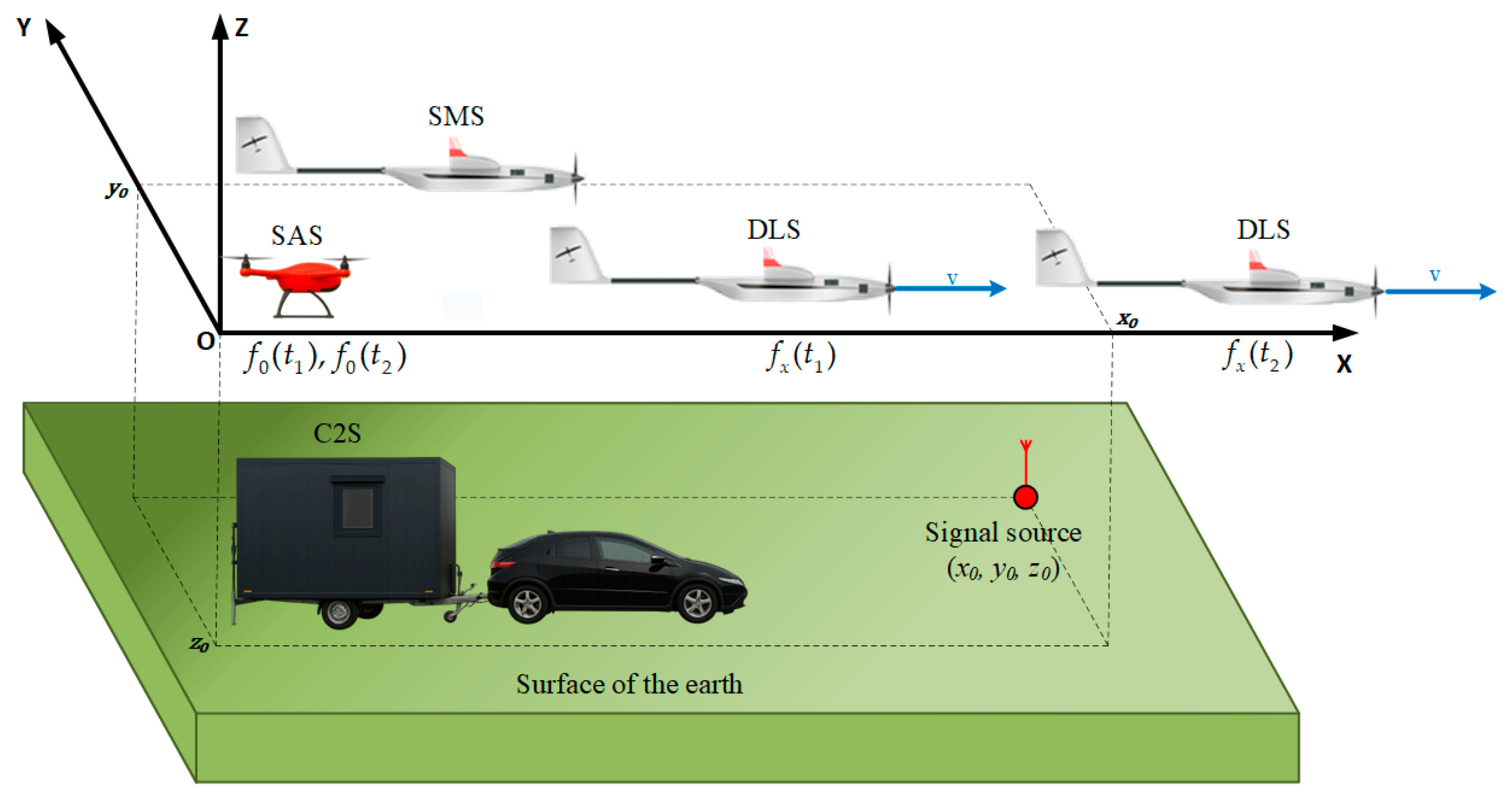
Figure 1. Concept model of UAV reconnaissance system.
Drones 09 00698 g001
Figure 2. Current variant of DLS implementation.
Drones 09 00698 g002
Figure 3. DJI Matrice 300 RTK with mounted DLS.
Drones 09 00698 g003
Figure 4. Exemplary spectra and spectrograms of signals received by (a) fixed or (b) mobile sensor.
Drones 09 00698 g004
Figure 5. Exemplary acoustic signal structure (consisting of two tones—with fixed and time-varying frequencies) modulated and emitted by AN/PRC-152A.
Drones 09 00698 g005
Figure 6. Test-bed for acoustic Doppler effect measurement.
Drones 09 00698 g006
Figure 7. Spatial scenario for emulation studies (based on Google Maps [35]).
Drones 09 00698 g007
Figure 8. Doppler curves obtained during emulation tests for three carrier frequencies f 0  of transmitted signal.
Drones 09 00698 g008
Figure 9. Average location error obtained for emulation tests, three carrier frequencies f 0  of transmitted signal and t A = 30   s .
Drones 09 00698 g009
Figure 10. Empirical CDFs of location errors for emulation tests, three carrier frequencies f 0  of transmitted signal, t > 32   s , and t A = 30   s .
Drones 09 00698 g010
Figure 11. AN/PRC-152A as transmitting part of test-bed.
Drones 09 00698 g011
Figure 12. Example spectrum of signal recorded during empirical measurements in entire signal bandwidth analyzed by DLS.
Drones 09 00698 g012
Figure 13. Spectrum of the AM modulated signal by AN/PRC-152A.
Drones 09 00698 g013
Figure 14. Empirical curves of DFS f D ( t ) , carrier frequency f 0 ( t ) and instantaneous frequency f x ( t ) of signals received by DLS and SAS, respectively, for carrier frequency of signal emitted by the Tx equal to 869 MHz.
Drones 09 00698 g014
Figure 15. Windowing idea used for determining current Tx position.
Drones 09 00698 g015
Figure 16. Empirical CDFs of location errors in empirical tests for two carrier frequencies f 0  and  t A = 10   s .
Drones 09 00698 g016
Figure 17. Comparison of empirical CDFs of location errors obtained for emulation (for t > 32   s ) and empirical tests and t A = 30   s .
Drones 09 00698 g017
Table 1. Comparison of four different Doppler-based localization methods.
MethodTypeMin. sensors (UAVs) RequiredSensor motion
Required
Time Synchronization RequiredKnown Transmit
Frequency Required
Computational
Complexity
Localization
Accuracy
Key AdvantagesMain Limitations
FOATwo-step1YesNoYesLowModerateSimple, requires only one UAVRequires known
frequency,
sensitive to drift
SDFTwo-step1YesNoNoLowModerateLow-cost, single UAV, unsynchronizedRequires motion and accurate
trajectory
FDOATwo-step2No
(relative
motion)
YesNoMediumHighGood accuracy, robust to noiseSensitive to
synchronization and clock drift
DPDOne-step3–4NoYesNoHighVery highHighest accuracy, robust in low SNRHigh complexity, needs
synchronization and computing
Table 2. Location errors in emulation tests for three analyzed frequencies, t 30   s , and t A = 30   s .
Tested Carrier
Frequency  f 0  (MHz)
Location Error (m)
min ( Δ r ¯ ( t ) ) max ( Δ r ¯ ( t ) ) μ Δ r ¯ σ Δ r ¯
1257.9131.247.240.3
25013.9101.028.816.8
5006.9154.121.134.2
Table 3. Location errors in emulation tests for three analyzed frequencies for t > 32   s  and t A = 30   s .
Tested Carrier
Frequency  f 0  (MHz)
Location Error (m)
min ( Δ r ¯ ( t ) ) max ( Δ r ¯ ( t ) ) μ Δ r ¯ σ Δ r ¯
1257.9131.245.941.1
25013.943.524.86.7
5006.917.512.13.0
Table 4. Comparison of localization errors in empirical studies for two carrier frequencies, each tactical radio and t A = 10   s .
Tested RadioTested Carrier Frequency  f 0 (MHz)Location Error (m)
min ( Δ r ( t ) ) max ( Δ r ( t ) ) μ Δ r ¯ σ Δ r ¯
1350.811.8826.5020.495.29
869.04.5930.8315.757.54
2350.814.6138.0120.185.09
869.011.4138.0118.444.45
3350.812.6739.7722.868.26
869.05.9289.4420.5713.54
4350.814.4131.4021.124.83
869.014.4152.1021.678.02
5350.811.3041.3523.747.48
869.011.3041.3522.965.40
Table 5. Comparison of location errors in empirical studies for two carrier frequencies and three acquisition times.
Acquisition Time  t A (s)Tested Carrier Frequency  f 0 (MHz)Location Error (m)
min ( Δ r ( t ) ) max ( Δ r ( t ) ) μ Δ r ¯ σ Δ r ¯
10350.811.3041.3521.786.34
869.04.5989.4420.078.53
20350.84.2089.7628.2914.72
869.03.34179.2426.0217.54
30350.86.24235.8637.1128.21
869.04.52235.8632.3726.52
Table 6. Comparison of localization error for emulation and empirical studies for four tested carrier frequencies and t A = 30   s .
Tested   Carrier   Frequency   f 0 (MHz)Location Error (m)
min ( Δ r ( t ) ) max ( Δ r ( t ) ) μ Δ r ¯ σ Δ r ¯
250.013.9101.028.816.8
350.86.24235.8637.1128.21
500.06.9154.121.134.2
869.04.52235.8632.3726.52
Disclaimer/Publisher’s Note: The statements, opinions and data contained in all publications are solely those of the individual author(s) and contributor(s) and not of MDPI and/or the editor(s). MDPI and/or the editor(s) disclaim responsibility for any injury to people or property resulting from any ideas, methods, instructions or products referred to in the content.