Article

Novel Twist Morphing Aileron and Winglet Design for UAS Control and Performance

by
Mir Hossein Negahban
,
Musavir Bashir
,
Clovis Priolet
and
Ruxandra Mihaela Botez
*
LARCASE, Department of System Engineering, École de Technologie Supérieure, Université du Québec, Montreal, QC H3C 1K3, Canada
*
Author to whom correspondence should be addressed.
Drones 2024, 8(8), 392; https://doi.org/10.3390/drones8080392
Submission received: 18 June 2024 / Revised: 2 August 2024 / Accepted: 10 August 2024 / Published: 13 August 2024
(This article belongs to the Special Issue Dynamics Modeling and Conceptual Design of UAVs)

Abstract

:
This study introduces a novel “twist morphing aileron and winglet” design for the Unmanned Aircraft System UAS-S45. Improving rolling efficiency through twist morphing ailerons and reducing induced drag through twist morphing winglets are the two main objectives of this study. A novel wing design is introduced, and a high-fidelity gradient-based aerodynamic shape optimization is performed for twist morphing ailerons and twist morphing winglets, separately, with specified objective functions. The twist morphing aileron is then compared to the conventional hinged aileron configuration in terms of rolling efficiency and other aerodynamic properties, in particular aircraft maneuverability. The results for twist morphing ailerons show that the novel morphing design increases the aileron efficiency by 34% compared to the conventional design and reduces induced drag by 61%. Next, twist morphing winglets are studied regarding the induced drag in cruise and climb flight conditions. The results for twist morphing winglets indicate that the novel design reduces induced drag by 25.7% in cruise flight and up to 16.51% in climb; it also decreases the total drag by up to 7.5% and increases aerodynamic efficiency by up to 9%.

1. Introduction

For decades, research on morphing wing technology has been proceeding at an ever-increasing pace, most of which have passed the conceptual design phase and are currently dealing with manufacturing challenges. Since this challenge is the last phase, meticulous consideration should be made concerning the development of morphing wings on real aircraft. Meanwhile, research on discovering other promising abilities of this technology is also ongoing. In a broad sense, morphing wing technology [1,2,3] replicates the flight patterns of birds, which have been optimized for millions of years, and this technology aims to discover these patterns and how to apply them on man-made flying objects. This broad field of research thus encompasses several disciplines, including aerodynamics, structures, materials, and control, making strong links and interchangeability among these disciplines essential for this field to advance.
Aerodynamic simulation is the logical first step to confirm the advantage of a morphing design. As confirmed by an aerodynamic study, morphing wing designs that have undergone the manufacturing process have demonstrated their promising capabilities [4]. Numerous morphing designs have been proposed, each concerning specific mission objectives and aircraft maneuverability as demonstrated by flight patterns. Span morphing or telescopic wings [5,6,7], drooped nose wings [8,9,10], variable sweep wings [11], upper surface morphing [12,13,14,15], variable thickness wings [16], and variable camber wings [17,18] are among the morphing wing types on which research has been conducted. Some of these designs, such as variable camber wings or Morphing Trailing Edge (MTE) [19,20,21], have garnered more attention than the others, due to their very promising potential in improving flight performance. For example, swept morphing has been used in the F-14 TOMCAT for many years, as it is considered one of the most successful morphing designs [22]. Given that each morphing wing is mainly proposed according to its specific mission objectives, if the mission objective is to enhance flight range or endurance in cruise flight, then camber morphing would be the first design choice due to its high potential for achieving those objectives [23].
The present research aims to find an appropriate morphing wing design to enhance the rolling efficiency, and to reduce downwash or induced drag. For aerodynamics researchers, the first wing components that come to mind for this mission objective are the ailerons and winglets, but the main question is related to the optimum morphing approach for this goal. So far, very little research has been done on morphing ailerons [24] or morphing winglets [25] with the aim to enhance rolling efficiency or to reduce downwash.
Jenett et al., in collaboration with NASA’s Ames Research Center [11], proposed a modular and reversibly assembled wing structure that can perform continuous spanwise twist deformation. Having lightweight and simple fabrication and maintenance is one of the advantages of their proposed mechanism. The purpose of this cellular composite structure morphing wing structure is to increase the roll efficiency compared to conventional aileron systems. This mechanism includes the flexible skin, wing structure, actuation, and control system. The final twist morphing wing design was attached to an arbitrary fuselage, and then tested in NASA’s Langley 12-foot low-speed wind tunnel. The test results showed that this morphing wing model could linearly alter the yaw. The wind tunnel tests also determined that active twist morphing was able to achieve stall mitigation. Manoranjan et al. [26] modeled a novel twistable morphing wing design with an elastomeric skin. The aerodynamic wing model was developed using Prandtl’s lifting-line theory, and the final design was tested in a low-speed wind tunnel equipped with flow visualization. It was found that using this method increased the range of angles of attack, a strong advantage for twisting wings. Garcia et al. [27] designed a morphing wing for a micro air vehicle to twist and perform the rolling maneuver. For twist deformation purposes, they used a series of rotating torque rods through which the twist morphing could be achieved. The flight tests showed that this type of morphing provided a substantial control authority for roll control, and that the roll rate was considerably increased proportionally to the yaw rate; in other words, it could generate pure roll and decrease the adverse yaw effect, thereby achieving an accurate flight path. An analytical solution was introduced by Phillips et al. [28], through which the roll response, yawing moments, lift, and induced drag of hinged and twisted ailerons could be predicted. This solution can be applied to arbitrary planform and spanwise variations of control surface deflection. They used Prandtl’s classical lifting-line theory, and the Fourier coefficients followed the wing geometry. This solution can also be applied to full-span twisting wings called “twisterons”. They showed that the induced drag was minimized by using a variable twist wing. Abdulrahim et al. [29] presented a twisting morphing wing for roll control, varying the gull wing angle to mimic bird wings in different flight patterns such as gliding and soaring. They tested their design on a micro aerial vehicle to study the effect of gull-wing morphing on flight dynamics. They concluded that twisting wingtips provide an excellent roll response and could improve the aerodynamic performance. Kaygan and Ulusoy [30] examined the twisting wing effectiveness in terms of aircraft performance and control by specifying the optimum twist angle. They used the Athena Vortex Lattice Method to predict aerodynamic performance. By considering several twisting configurations ranging from −8° to +8°, they showed that considerable aerodynamic performance could be gained from higher twist angles, which could be applied to ailerons, rudders, and elevators. A study was performed on the Airbus A320, revealing the promising benefits of twisting wings. A numerical analysis on twist morphing wings with a high-aspect-ratios for efficient control roll maneuvers was conducted by Pecora et al. [31]. They compared conventional hinged aileron configurations with twisted morphing ailerons in terms of aerodynamics and aeroelasticity, including the induced roll rate and reversal speed control. This study showed that linear or quadratic twist morphing wings not only outperformed conventional ailerons by nearly 1.6 times in terms of roll control effectiveness, but also more powerful and robust roll control could be achieved. This morphing strategy was applied on the wing by varying local leading-edge angles along the entire wingspan, in contrast to conventional ailerons. Their analysis also revealed that structural weight reduction could be expected using this unconventional morphing configuration. Rodrigue et al. [32] introduced a novel twist morphing wing in which a specified part of the wing span underwent a twist morphing, namely the wingtip, while the other part remained fixed, i.e., the part attached to the fuselage. The morphing part was composed of flexible and innovative composite materials to ensure a smooth twist. The prototype of the model was tested in a wind tunnel, and the results revealed that lift increased for angles of attack below 10 degrees. Moreover, in zero-lift conditions, the twisting part could generate lift and increase the lift-to-drag ratio by up to 13%. Ahmed et al. [33] established an aerodynamic shape optimization on a micro air vehicle (MAV) to find the optimal configuration of an asymmetric wing twist for a better roll control and minimized induced drag. This optimization was based on a gradient-based algorithm and was applied on two cases of symmetric and asymmetric wing twist with specific objective functions. These two morphing configurations were expected to reduce induced drag and achieve better roll control. Prandtl’s lifting-line theory was used during the optimization process to determine the load distribution along the span. The optimization results indicated that the induced drag was minimized using optimum asymmetric twist, and a good roll response was obtained. Stanford et al. [34] used a reference MAV with a flexible membrane wing to implement it through a torque-actuated wing structure. For this purpose, a static aeroelastic model was developed. They performed an optimization using a genetic algorithm on the proposed wing design to increase the steady-state roll rate and the lift-to-drag ratio. Using a single-torque-rod design, the roll rate was increased by up to 10% compared to its conventional wing design, while the lift-to-drag ratio was improved by up to 6.5%. Subsequently, optimizing the actuation mechanism with a multiple-torque-rod design increased the roll rate and lift-to-drag ratio by 34% and 6%, respectively, compared to the baseline design. Vos et al. [35] proposed a mechanism for actively controlling wing twist based on a wrapping deformation of the skin. A structural analysis was performed on the wrapping wing using the generalized thin-walled beam theory. Numerical and analytical models, in conjunction with wind tunnel tests, showed a 0.7 increase in lift corresponding to the maximum wing twist. It was found that wing wrapping positively influenced lift-induced drag and improved the lift-to-drag ratio at lower angles of attack. Their study confirmed that actively wrapping the twisted wing could improve roll control motion by ensuring a maximized lift-to-drag ratio. Rodrigue et al. [36] developed a novel actuation system for pure twist morphing wings using a smart soft composite, by which shape memory alloy wires were embedded in the structure designed in a cross-shaped matrix to produce a wing twist deformation. The results showed that the mechanism could make large twist angles with higher stability.
This paper presents a novel twist morphing aileron through which the rolling efficiency, rolling rate, and overall aerodynamic performance are investigated on the UAS-S45 as base model. The UAS-S45 is used for surveillance and reconnaissance purposes and is designed and manufactured by Hydra Technologies in Mexico. The impact of morphing ailerons on induced drag is also analyzed. The study is performed in several steps. First, asymmetric twist morphing ailerons are studied through aerodynamic shape optimization, and their obtained optimum configurations are compared with conventional hinged aileron configurations in terms of rolling efficiency and rolling rate to quantify the performance of the novel morphing design. Next, the symmetric morphing ailerons are studied in the same manner through aerodynamic optimization to evaluate the gain that can be achieved in induced drag reduction, after which the optimum design performance in terms of induced drag is compared to that of a conventional wing with winglets. The gradient-based optimization algorithm is established for all studies. Finally, the optimum morphing aileron designs for improved rolling maneuvers and reduced induced drag are presented and described in detail.

2. Asymmetric Analysis-Twist Morphing Ailerons

2.1. Implementation of a UAS-S45 Wing for Twist Morphing

Figure 1 shows the baseline wing for a UAS-S45 equipped with standard and modified flattened winglets. In this study, the wingtip is designed to be feasible for twist morphing applications. Therefore, any curvature on the wingtip should be eliminated as it will be created after the twist. Two alternatives could be utilized to achieve this goal: 1—elimination of the winglet; or 2—using a flattened winglet. The first alternative would eliminate the winglet’s impact on the wing; however, if the winglet shape is implemented in a flattened form (second option), its effects will be preserved after the twisting morphing of the wingtip. Therefore, in this study, the flattened winglet will be attached to the baseline wing, and by twist morphing, the impacts of the aileron and the winglet will be combined. This effect will be further studied in symmetric wing analysis to reduce the downwash.

2.2. Methodology Used for Asymmetric Twist Analysis (Twist Morphing Ailerons)

2.2.1. Roll Motion

Performing rolling maneuvers requires ailerons on both wings of an aircraft to deflect asymmetrically in upward and downward directions. The downward deflection increases the lift force on one wingtip, while the upward deflection on the other wing decreases the lift force as the wingtip enters the stall condition. The unequal spanwise lift distribution on both wingtips creates a moment around the roll axis which makes the aircraft roll clockwise (positive roll) or counterclockwise (negative roll) around the roll axis, depending on both left and right aileron configurations. For example, if the right aileron deflects upward and the left aileron downward, the aircraft will have a positive roll and vice versa. Figure 2 shows the UAS-S45 in a rolling maneuver.
During a rolling maneuver, a yawing moment is also created, which makes the aircraft yaw in the opposite direction of the roll. This unwanted yawing moment is called adverse yaw; however, since it is beyond the scope of this study, only the pure rolling maneuver is investigated here. In the rolling maneuver, several criteria exist to quantify the roll’s performance, including its power, rate, and efficiency. The roll control power can be obtained through strip integration [37]. The opposite deflection of the ailerons generates a roll moment around the roll axis that can be found by use of the following equation:
M z = L . y
where y represents the span length of the wing.
Equation (1) may be expressed in coefficient form by replacing M z with C m z Q S b , in which Q denotes the dynamic pressure, S the surface area, and b the span length, and therefore Equation (1) becomes [37]:
C m z = L   y Q S b = C l Q c y d y Q S b = C l c y d y S b
Equation (2), which represents the roll moment coefficient, is used in this comparative study between hinged and morphing ailerons, as it is directly proportional to the roll efficiency and roll rate. To obtain the local lift coefficient generated on the ailerons, C l in Equation (2) is replaced by local lift coefficient ( C l = C L α w τ δ a ) . Therefore, Equation (2) is integrated over the section of the wings containing the ailerons, which is expressed as:
C m z = 2 C L α w τ δ a S b y 1 y 2 c y d y
where C L α w is the lift curve slope, δ a is the aileron deflection angle, and τ denotes the derivative of the angle of attack with respect to the angle of deflection ( d α d δ a ). Finally, by taking the derivative from Equation (3) with respect to angle of deflection ( δ a ) , the aileron control power is obtained, as follows:
C m z δ a = 2 C L α w τ S b y 1 y 2 c y d y
The aileron control power ( C m z δ a ) measures the moments variations per unit of aileron deflection. It is evident that when a higher roll moment is produced, the control power is high, indicating that an aileron is more effective.
The flow solver used for all the optimizations in this study is the OpenFOAM’s steady state flow solver, “simpleFoam”; therefore, only pure roll motion (no adverse yaw effect) in steady state form is formulated (as noted above). The roll motion can be written as a second-order differential equation [37]:
R o l l i n g   m o m e n t s = I z ϕ ¨ = 𝜕 M z 𝜕 p Δ ϕ ˙   +   𝜕 M z 𝜕 δ a Δ δ a
where ϕ denotes the roll angle about the roll axis, p is the dimensionless roll rate, and 𝜕 M z 𝜕 δ a Δ δ a is the roll moment created by aileron deflection. Since the roll rate ( p ) is equal to Δ ϕ ˙ , Equation (5) can be reduced to a first-order equation as follows:
I z Δ p ˙ = 𝜕 M z 𝜕 p p   +   𝜕 M z 𝜕 δ a Δ δ a
Next, by replacing 𝜕 M z 𝜕 p I z with M z p , 𝜕 M z 𝜕 δ a I z with M z δ a , and assuming τ = 1 M z p , Equation (6) is solved and the following time-dependant equation is obtained:
Δ p t = M z δ a M z p 1 e t τ Δ δ a
where τ is the roll response time and lower τ values are interpreted as rapid roll motion. To obtain steady-state pure roll motion, t is assumed large enough ( e t τ 0 ) to account for a steady-state solution; therefore, Equation (7) changes to:
ω z = M z δ a M z p Δ δ a = 2 U b C m z δ a C m z p Δ δ a
where ω z is the roll rate about the z-axis, C m z δ a is the aileron control power (Equation (4)), C m z p is the roll damping coefficient, and Δ δ a is the aileron deflection angle. Since C m z p is always negative, the ultimate roll rate will be positive. Therefore, Equation (8) indicates that increasing roll moment not only increases aileron control power, but also increases the roll rate.
For decades, conventional ailerons have performed rolling maneuvers through their hinged deflections, and so rolling efficiency and determining how well this maneuver was performed has been directly dependent upon aileron performance. In some aircraft, particularly in commercial jets with large swept wings, since ailerons’ efficiency is reduced, spoilers are used for rolling maneuvers because of their quick actuation to partially recover the reduced efficiency of ailerons. Inspired by nature and rolling maneuvers of birds, the same pattern can be implemented in aircraft, in which wingtip twist deformation could be used instead of aileron deflection. Morphing is the first technology that can lead to this objective. The rolling maneuver can be made more efficient by smoothly twisting the wingtip instead of using discontinuous and sharp deflections of ailerons or spoilers. We present in this paper novel twist morphing ailerons that can achieve such rolling maneuvers. For this purpose, the UAS-S45 is used as the base model, for which both hinged and morphing ailerons are studied. As expressed through Equations (1) to (8), the roll moment coefficient is the best comparison parameter because it influences both the aileron’s control power and roll rate, and it is therefore used as the primary measure in this study to compare the performance of hinged and morphing ailerons. The aerodynamic optimization is performed on the morphing of asymmetric ailerons, and then, after their optimum configurations have been obtained, their performance is compared to that of hinged ailerons.

2.2.2. Optimization of Asymmetric Morphing Ailerons for Rolling Maneuver

The optimization uses the DAFoam (Discrete Adjoint with OpenFOAM) optimization framework, a high-fidelity multidisciplinary optimization framework based on a gradient algorithm. Since its development in 2019 [38], it has been used in several benchmark studies [39]. In the literature, most of the aerodynamic optimization frameworks use low-fidelity potential flow solvers in the optimization loop; however, DAFoam takes advantage of OpenFOAM, in which the flow is simulated through Reynolds-averaged Navier–Stokes (RANS) equations, leading to more accurate optimization results. Moreover, DAFoam is an appropriate framework for three-dimensional optimizations, in which a whole wing or aircraft is optimized, involving hundreds of design variables. This framework is explained in detail in [23].

2.2.3. Wing Parametrization

Special considerations should be taken when large-scale optimization is performed. Parametrization or mathematical definition of a wing is a crucial step in the optimization algorithm. Since the whole wing is optimized in this study, the number of design variables is very high. “Constructive” parametrization techniques [40] cannot handle such a high number of design variables; therefore, the best candidates for this type of parametrization are the “deformative” parametrization techniques, in which the mathematical definition of the geometry is independent of design variables. This study uses the Free-Form Deformation (FFD) technique to handle hundreds of design variables. The initial objective for developing the FFD technique was related to its use in graphics [41]. However, it is an excellent tool in engineering problems, especially in optimization. Since its development in 1986, several modifications and improvements have been made, particularly in aerodynamic optimization [42,43], and today it is the best method in aircraft or wing optimization (see [44] for more details). In this technique, the geometry is embedded inside the FFD block, which has a defined number of control points, and this embedded geometry is morphed by the displacement of control points. In this study, the baseline wing design is embedded inside the FFD block. Since the objective of the optimization refers to the ailerons and wingtips, only the control points in these regions have the freedom to move. The rest of the control points (around the main flaps and the wing root) are confined with zero displacement. Figure 3 illustrates both wings (right and left) inside the FFD block, where active control points are shown in green. These control points can move downwards in the left wing and upwards in the right wing. The blue FFD boxes surround the static wing section, and the red ones the wing section where its twist deformation occurs.
The number of control points directly impacts the optimization results, as shown in our previous work [45]; therefore, the optimum number of control points in this study was determined through trial and error. In this procedure, several criteria are considered to determine the optimum number of control points. These criteria include optimization convergence, computational time, optimality error, and feasibility of the deformation. Based on these criteria, different numbers of control points were examined and finally 64 control points were chosen for each wing model (Figure 3).

2.2.4. Optimization Setup

The objective of this paper is to optimize the proposed twist morphing aileron to achieve better rolling efficiency. The straightforward optimization method consists in defining the objective function in terms of rolling moment or rolling efficiency maximization; however, since each wingtip twists in opposite directions (one upward, one downward) to perform the rolling maneuver, an alternative simple way is established in this work, in which the optimization process is divided into two separate processes, one for the left wing and the other one for the right wing. The objective function of each wing is based on the lift force on the wingtip; in one wing, the lift force is maximized, and in the other wing, it will be minimized to create an unbalanced lift distribution on the whole wingspan. While the optimization is performed for one wing, the other wing is confined with no deformation during the optimization. The boundary condition for the opposite wing is defined in a way that the opposite wing is not deformed during the optimization by constraining the control points of FFD block to zero deflection on the opposite wing. The two optimization frameworks are shown in Table 1, in which the entire optimization setup, including the objective function, the constraint function, and the number of design variables are specified.
As seen in Table 1, the left wing is optimized to maximize the lift, while the right wing is optimized to minimize the lift. They have the same geometrical constraints to maintain equal deformations on both wings. The control points are confined to upward and downward displacements for minimizing and maximizing the lift force, respectively. Design variable constraint ( y ) sets the limits for these vertical displacements along the y-axis in the FFD block. The reference axis of the twist variable is at 50% of the chord, and its starting point in the spanwise direction is at 50% of the wingspan, which corresponds to the starting point of the ailerons in hinged configuration. Both wings follow the same optimization process as shown in Figure 4, except that the objective function relates to either lift maximization or minimization.
As shown in Figure 4, the optimization uses different modules in Python. Within the PyGeo module, surface geometry parametrization is implemented through the FFD, and the constraints and their derivatives ( d c / d x ) are also computed within this module. Next, all changes in surface geometry are applied to the surface mesh. The volume mesh is then deformed, corresponding to these changes in the surface geometry, all of which are implemented within IDWarp (mesh morphing module). Finally, the corresponding volume mesh, Xv, is given as an input to the flow solver, OpenFOAM, to compute the specified objective function that works the best with the constraint. However, since the objective function f is dependent on both design variables x and state variables w, ( f = f ( x , w ) ), the discrete adjoint solver computes the total derivative of f , ( d f / d x ) , also called the sensitivity of the objective function. Similarly, the sensitivities of constraint functions are also computed and transferred to the IPOPT algorithm, which will find the solution using optimization iterations. Note that the objective function for the left wing is lift maximization, while for the right wing it is lift minimization.
The optimization was performed in cruise flight conditions, where the cruise speed for UAS-S45 was 70 knots (28.3 m/s), the initial angle of attack was zero degrees, and the mission altitude was 15,000 ft.

2.3. Results and Discussions for Asymmetric Twist Analysis

2.3.1. Morphing Ailerons

Once the optimization was performed for both right and left wings, the optimum wing configurations were attached to the fuselage to evaluate the UAS rolling efficiency. In this phase, the simulation was performed in OpenFOAM with a high number of meshes (14,199,957 elements). Since there are strong vortices and flow recirculation around the wing tip, finer elements were used around the wing tip to have a better visualization of the airflow around morphing ailerons. This section presents only the results expressed in terms of pressure, vorticity, and velocity streamlines, while the quantitative aerodynamic properties, such as the rolling efficiency, are presented and discussed in subsequent sections, where they are compared with hinged ailerons results. Figure 5 illustrates the static pressure contours on the top and bottom of the UAS-S45.
The static pressure contour (Figure 5) clearly shows the unbalanced pressure distribution on the left and right wingtips, where the downward twist produced higher pressure on the bottom surface (left wing, Figure 5B), and the upward twist (right wing, Figure 5A) produced it on the upper surface. The advantage of using morphing ailerons is that the pressure variations on the wing surface, both in chordwise and spanwise directions, are very smooth, so that there is no pressure peak on the transition surface from solid to twisted wing.
Very good visualization of the flow around the twisted ailerons can be captured by velocity streamlines, as shown in Figure 6, where the airflow recirculation and velocity magnitude variation were captured perfectly. Figure 6A,C,E show the downward twisted morphing aileron from its forward, isometric, and top views, respectively, and Figure 6B,D,F show the upward twisted morphing aileron in the same manner. Figure 6G,H illustrate the UAS-S45 equipped with morphing ailerons.
As depicted by these Figures, the only flow characteristic that makes the aircraft roll is the opposite flow distribution, wherein for a downward morphed aileron, flow is mainly concentrated on the upper surface of the wingtip, but in an upward morphed aileron, the flow concentration is mainly on the wingtips’ lower surface. This opposite flow distribution creates opposite pressure distribution, as shown in the pressure contours in Figure 3, which leads to unequal lift distribution and the generation of roll moment. Figure 6C,D show the flow recirculation on both morphing ailerons, wherein for the downward twisted aileron, it emerges on the upper surface, and for the upward twisted aileron, it is on the lower surface. Thanks to the wingtip’s circular curvature, this recirculation has a restricted propagation zone, and just past the wingtip, its magnitude approaches zero. Moreover, since there is a smooth transition between the solid and morphing parts of the wing, the flow has no turbulence at the start of the twist (Figure 6G,H).

2.3.2. Hinged Ailerons

To compare the morphing with the hinged ailerons, they must be simulated under the same flight conditions (speed, pressure, angle of attack, angle of deflection) with the same simulation setup (number of elements). The simulation of the hinged aileron is conducted in ANSYS Fluent, a high-fidelity flow solver similar to OpenFOAM. However, the simulation of the hinged flap does not include any optimization; it is pure aerodynamic simulation. Therefore, the morphing aileron’s configuration is obtained first, through optimization, and then the corresponding data, including the optimum angle of attack and angle of deflection, are transferred to the hinged aileron simulation to determine the most accurate comparison in terms of overall aerodynamic performance, rolling efficiency, rolling moment, and rolling rate.
In a hinged flap, whether it is the main flap, an aileron, or any other control surface, the deflections are either pure upwards or downwards deflections. The only effective parameters on lift force are the geometric parameters of that control surface, such as its size and position. In [46], Caughey quantified the effectiveness of a control surface by considering flap deflection magnitude and size in terms of chord length. As seen in Figure 7, control surface or flap effectiveness is proportional to its size.
Flap effectiveness can be directly interpreted into lift generation; in other words, according to Figure 7, the flap effectiveness corresponding to a flap at 25% of a chord has an efficacy of 0.6, which means that it can generate 60% of the lift force. Despite the main flap being restricted only to its upward or downward deflection, no matter whether it is morphed or hinged, since the ailerons are usually located at the wingtip, they have other forms of deformations rather than up or down, meaning that the ailerons can also have twist deformation, which can be more feasible than that of the hinged aileron. This section focuses on hinged ailerons; a thorough comparison between morphed and hinged ailerons is presented in Section 2.3.3.
This study investigates hinged ailerons on the UAS-S45 with its standard winglets and was performed using the Spalart–Allmaras turbulence model. The flight conditions chosen for this study were the cruise flight, where the cruise speed for UAS-S45 was 70 knots, the ceiling altitude was 15,000 ft, and the effective angle of attack was zero degrees. These are the same conditions applied to morphing ailerons in the previous section (Section 2.2). The hinged ailerons were deflected from 0° to 10° with increments of 2°. Within this range of deflections, aerodynamic parameters were evaluated, including lift and drag coefficients both for the whole UAV and each wing separately, rolling and pitching moments, and pressure coefficients.
Since there are tiny gaps around the hinged aileron, the convergence of the simulations is very sensitive to the element size. Therefore, special consideration was taken in the meshing part. An unstructured mesh with 10 inflation layers around the UAS surface was used with the first element size of 0.001 m corresponding to Y+=50. To reduce the computational cost, a density box with finer elements was used around the UAS, making the element’s size much coarser; this feature substantially reduces the computational time. Figure 8 and Figure 9 illustrate the meshing detail.
As depicted in Figure 9, specific parts of the wings are refined to get better results. This is generally the case for the ailerons, where the gaps between them and the wing create eddies, and the simulation’s convergence is highly sensitive to these discontinuous parts of the wing. It is also the case with the leading and trailing edges, as they present high pressure and velocity differences.
A mesh independence study was performed on the UAV with an 8° aileron deflection. Three different elements were evaluated for each of three meshes. Table 2 and Table 3 show the numbers of elements for each of these three meshes and their corresponding error percentages, respectively.
As seen in Table 3, having Mesh 1 as a reference mesh, due to its accurate results and very good convergence, the relative error for each element size for the lift coefficient is zero; however, for the drag coefficient, the maximum error is 5% by having Mesh 1 as reference mesh. The final mesh chosen for this study is Mesh 2, which has the intermediate number of elements, and an error of 4%, which is less than 5%; therefore, it lies within the acceptable range.
The simulation of hinged ailerons was done by an evaluation process of the aerodynamic parameters for different angles of deflection of ailerons. Figure 10 shows the variations of the lift coefficients for the right and left wings separately, as well as the total lift coefficient for the whole UAS. Note that for the left wing, the angle of deflection (AOD) is positive as it deflects downward, and for the right wing, which has an upward deflection, the AOD is negative. As seen in Figure 10, the lift for the left wing is increased as the AOD increases, while for the right wing, the lift decreases due to the upward deflection, approaching zero lift conditions as the AOD increases. Nevertheless, the net lift force for the whole UAS is independent of the angle of deflection and remains constant. The linear regressions calculated for the wings are 0.963 and 0.995 for the left and right wings, respectively, values that are very close indeed. For the chosen flight condition, the net lift force for the whole UAS equals 0.29. As a result of the unequal lift distribution on left and right wings ( C L r i g h t w i n g < C L l e f t w i n g ), the UAV rolls towards the right (a positive roll).
The rolling moment is obtained from the ANSYS Fluent default outputs and by manual calculation by subtracting the right wing’s CL from that of the left wing. Figure 11 displays the results obtained by both methods, showing that they both follow the same trend, which is increasing linearly with the deflection angle. However, there is an error of less than 10% for the angles of deflections greater than 2 degrees, which is because the ANSYS Fluent considers the whole UAS in the calculation of rolling moment, while in the manual calculation, only the wings are considered.
The drag coefficient was also calculated. Figure 12 shows the drag variations for the whole UAS for different angles of deflection, revealing an increasing trend as the AOD increases. However, by comparing the slope of the drag coefficient with those of the lift coefficient, these slopes are 0.021 and 0.0004 for CL and CD, respectively, which are 98% lower than the CL variations. Therefore, drag variations with aileron deflection are not notable compared to lift variations for the whole UAS, and thus can be neglected.
The static pressure contour for the UAS with hinged ailerons is shown in Figure 13. The discontinuity in the gaps around the ailerons clearly shows the peak static pressure boundaries. In addition, these discontinuities also contribute to the wingtip-induced drag, as they facilitate the mixture of high-pressure flow on the lower surface and low-pressure flow on the upper surface, and thus create additional vortices along with wingtip vortices. However, as observed in twist morphing ailerons (Figure 5), the variation of the static pressure is smooth and coherent throughout the span; in fact, no boundaries can be determined for ailerons due to the elimination of discontinuities, and the probability of flow mixture around ailerons was zero. The pressure peaks in the hinged ailerons will be further illustrated through pressure coefficient diagrams and will be compared with those of the morphing ailerons in the next section.

2.3.3. Comparison of Hinged and Morphing Ailerons

In this section, a comparison is drawn between hinged and twist morphing ailerons in terms of roll moment and overall performance. As explained earlier, the comparison of their roll moments evaluates the performance of ailerons both in terms of roll rate and control power. Table 4 shows the comparison of these ailerons in terms of their roll moments. Unlike hinged ailerons, the twist deformation of the morphing ailerons is not constant spanwise; therefore, the comparison is drawn by having the same maximum vertical displacement of the ailerons edge, which is equal to ± 61.2 mm both for hinged and morphing ailerons. Note that positive and negative displacements refer to upward and downward displacements, respectively.
By considering the roll moment coefficient as an index for aileron performance, Table 4 shows that using twist morphing ailerons increases the roll moment by 34% compared to conventional hinged ailerons. According to Equation (4) and Equation (8), an increase in roll moment is directly interpreted as an increase in the ailerons’ control power as well as in their roll rate, translating into higher aileron efficiency and rapid roll maneuver, respectively. Meanwhile, due to the elimination of the discontinuities around the ailerons in their morphing configuration, induced drag is also considerably decreased (by 61%) in morphing ailerons, which means that flow mixture and vertices due to gaps are of no concern in twist morphing ailerons.

3. Symmetric Twist Analysis (Twist Morphing Wingtips)

3.1. Twist Morphing Wingtips
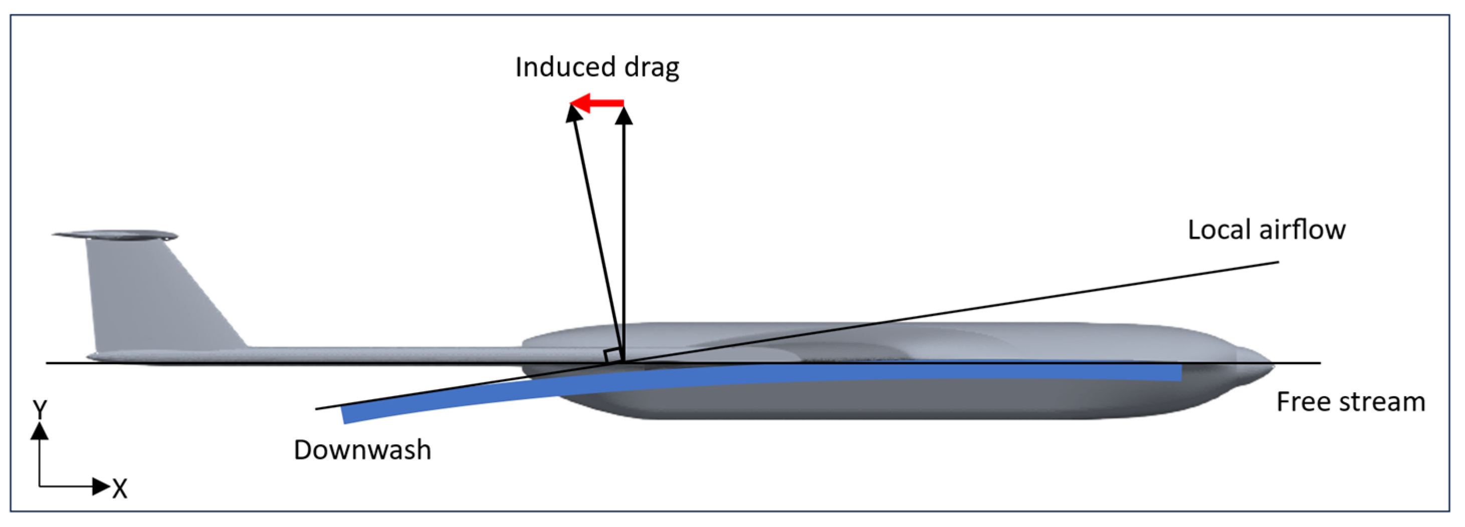
In this section, twist morphing is applied on the same wing configuration introduced in Section 2.1, the UAS-S45 wing with a flattened winglet. However, this section aims to reduce the induced drag under different flight conditions, including climb and cruise.

3.2. Induced Drag

Drag force imposed on an aircraft has different components, each of which arises from a different phenomenon. In general, drag is divided into two main components: parasite (or parasitic) and induced drag. The former consists of three different types: form drag (pressure drag), skin friction, and interference drag. In the form drag, the flow resistance originates mainly from an aircraft’s shape, while the skin friction is due to air viscosity on an aircraft’s surface, and interference drag arises from turbulent flow at different parts of aircraft, namely, the wing root. On the other hand, the induced drag arises from the generation of lift force and is directly dependent on the amount of lift produced on the wings. It is well known that the pressure gap on the upper and lower surfaces of a wing creates the lift force; however, on the wingtip, the high-pressure flow finds a way to move to the upper surface and mix with the low-pressure flow. This flow mixture at the wingtip creates wingtip vortices, where the resultant vector of these vertices is in the opposite direction of aircraft, and thus an amount of energy is lost due to the generation of these vortices, reducing aircraft aerodynamic efficiency. In addition to this adverse effect, these wingtip vortices also contribute to extra drag creation due to producing local airflow direction, meaning that when these vortices are generated, the flow circulation on the wingtip pushes the airflow downward, which is called downwash, and the wing experiences local airflow rather than free stream; therefore, the lift force direction inclines backwards, being perpendicular to local airflow, and the magnitude of the inclined lift force is equal to the induced drag magnitude (Figure 14).
The induced drag is calculated from the following formula:
C D i = C L 2 e × π × A R
where A R is the wing aspect ratio and e is its efficiency factor, which ranges from 0.7 to 1. For a wing with an elliptic lift distribution (an ideal wing), e = 1, while for a typical rectangular wing, it equals 0.7. According to Equation (9), the induced drag is dependent on one aerodynamic parameter, CL, and one geometrical factor, A R , and is reduced either by reducing the lift or by increasing the aspect ratio. In this study, both parameters are met to minimize the induced drag by keeping the total drag constant. As shown in Figure 1 in Section 2.1, the proposed wing aspect ratio is increased by 19.6% compared to the baseline wing without a winglet, and by 9% compared to the baseline wing with a standard winglet for UAS-S45. This reduces induced drag to some extent; however, since the induced drag is proportional to the square of the lift coefficient (Equation (9)), an infinitesimal reduction in the lift coefficient would highly reduce the induced drag.

3.3. Methodology Used for the Symmetric Twist (Twist Morphing Wingtips)

Since the aim is to reduce the induced drag, an optimization was performed to minimize the lift coefficient while keeping the total drag constant. Minimizing the lift is directly proportional to induced drag reduction according to Equation (9); however, since the wingtip twist causes an increase in total drag, a constraint function is defined to keep the total drag constant during the optimization. The same optimization framework was used in the asymmetric analysis for rolling efficiency; however, in this section, the only differences are seen in the wing parametrization and in the objective function. Since this section only deals with wing tip vortices, which are the leading cause of induced drag, the FFD block is implemented according to Figure 15.
As shown in Figure 15, the FFD block in blue color represents the solid part where no twist exists, and the FFD in red block shows the twisting section of the wing where the twist deformation is locally restricted to the wingtip; therefore, it will not influence the wing shape in the blue block. The active control points allowed to move upwards and downwards are located on the wingtip and shown in green. A different number of control points were established; however, considering the feasibility of deformation, six control points, three on the upper and three on lower wing surfaces, were chosen on the wingtip. Once the optimum FFD block was determined, the optimization setup was specified according to Table 5.
As shown in Table 5, the minimization of the square of the lift coefficient is constrained by the total drag coefficient; therefore, the optimum configuration will have a lower or the same total drag coefficient as that of the baseline wing drag. As the objective minimizes C L to reduce induced drag, although this involves a slight reduction in lift, it does not significantly alter the specified flight conditions; rather, it indicates a minor adjustment to improve efficiency.
By maintaining the same angle of attack and flight speed, we ensure that the overall flight conditions remain stable.

3.4. Results and Discussion for Symmetric Analysis (Twist Morphing Wingtip)

In this study, the model optimization was performed for two flight conditions: cruise and climb. Once the optimum configuration was obtained for each flight condition, it was compared with that of the baseline wing with and without winglet and with the unmorphed baseline wing in terms of induced drag. Figure 16 illustrates the four wings with different wingtip configurations, and Table 6 shows the results obtained for cruise flight conditions for these wingtip configurations.
As shown in Figure 16, three types of wingtips were investigated in this study. Model B is the wingtip attached to the baseline wing where there is no deformation on the wingtip; it is simply reduced in thickness, leading to a nearly sharp wingtip. This flattened winglet is proposed as the base model for the twist morphing wingtip, as mentioned in Section 2.1, and it is not the final design in this study. Wingtip Model C is the standard winglet currently used on the UAS-S45, and Model D is the proposed twist morphing wingtip design after being optimized for cruise flight condition. As depicted in Table 6, comparisons are drawn among these wingtip configuration performances. Wingtip models B, C, and D were compared to the baseline UAS-S45 wing without winglet (A) in terms of induced-drag variations. The results indicate that the twist morphing wingtip (Model D) reduced induced drag by 25.7%, while the standard winglet (Model C) increased it by 5.35%. Moreover, when the proposed wingtip is unmorphed (model B), the induced drag is reduced by 7.28%. These improvements are primarily due to the lift coefficient reduction after the optimization, and secondarily due to the increase of aspect ratio by 19.6%. According to Equation (9), CL reduction and aspect-ratio increase lead to reduced induced drag; however, the effect of CL reduction is substantial compared to the AR effect. As shown in Table 6, the drag coefficient remained constant for both the baseline wing and the wing with a twist morphing wingtip, due to the drag coefficient constraint in the optimization (Table 4). Figure 17 shows the velocity streamlines for all four wingtip types in cruise flight.
The mixture of low-pressure flow with high-pressure flow is evident in Figure 17A, where there is no winglet. Because of the turbulent flow mixture, wingtip vortices are created, leading to lift-induced drag. However, using different types of wingtips, especially a twist morphing wingtip, the turbulent flow mixture approaches zero, which results in a noticeable reduction in induced drag.
To further examine the superior advantages of twist morphing wingtips, this study optimizes the proposed wingtip in climb flight conditions. Since a climb flight experiences higher angles of attack than a cruise flight, the effect of induced drag is more conspicuous in climb than in cruise flight. Three climb angles (5°, 8°, 10°) were studied to find the trend by which the induced drag is increased. Table 7 shows the flight parameters used for cruise and climb flight conditions, and Figure 18 shows the optimum morphed configurations for each flight condition.
As shown in Figure 18, as the angle of attack increases, the wingtip on the trailing edge morphs upward (Figure 18A), while the leading edge morphs downward (Figure 18B), which results in an increased twist on the wingtip as the angle of attack increases; therefore, a higher twisting effect is observed in climb than in cruise flight. This observation means that the twisting impact is proportional to production of induced drag, and as more induced drag is produced, a higher twist intensity is required to reduce its impact.
Next, the optimization results are obtained for the climb flight condition. As in the case of cruise flight, the optimization for climb follows the same setup described in Table 5. Once the optimum configuration of a twist morphing wingtip is found, a comparison is drawn with wingtip types A, B, and C in terms of induced drag, total drag, and lift-to-drag ratio. Figure 19, Figure 20 and Figure 21 show the results obtained.
Figure 19, Figure 20 and Figure 21 clearly show the efficiency of twist morphing wingtips through different aerodynamic parameters, including induced drag, total drag, and lift-to-drag ratio. Table 8 summarizes these results in terms of induced drag reduction for three wingtips compared to that of the baseline wing.
As shown in Figure 19 and Table 8, all three wing tip configurations (types B, C, and D) reduced the induced drag for all studied angles of climb. However, the amount by which the induced drag is reduced is much greater for the twist morphing wingtip (type D), where it reduces the induced drag by up to 16.51%, while wingtip types B and C reduced it by up to 12.04% and 3.92%, respectively. In addition, Figure 20 shows that the total drag was also reduced by using wingtips other than baseline wings, and again, the twist morphing wingtip produced the highest total drag reduction compared to other wingtip types with a 0.16% reduction for cruise flight and 7.5% for climb. During the optimization process, the total drag was constrained to be less than or equal to the initial total drag; therefore, while minimizing CL, the total drag was reduced as well, which contributes to the overall improvement in aerodynamic efficiency. Finally, Figure 21 reveals that the lift-to-drag ratio, or in other words, the aerodynamic efficiency of the wing, was also improved, and the highest aerodynamic efficiency belongs to the morphing wingtip, with a gain of up to 9% compared to the baseline model (type A). The overall improvement in aerodynamic performance is primarily because of a reduction in total drag during the optimization. The twist morphing wingtip outperforms the other wingtip types in terms of aerodynamic efficiency, total drag, and induced drag, making it an efficient wingtip configuration.

4. Conclusions

This study presents another of the many advantages of morphing wing technology. Twist morphing was this study’s main morphing approach, and the objectives were accomplished as expected. This morphing approach was investigated on the wingtip with two main goals: 1—improving rolling maneuver by replacing hinged ailerons with twist morphing ailerons, and 2—reducing induced drag at the wingtip through twist morphing wingtips. For this purpose, a novel wingtip model was proposed as the baseline model for the twist morphing approach. The aerodynamic shape optimization was performed for both objectives to find the optimum configuration with the specified objective function. The results obtained for the twist morphing ailerons revealed that this novel morphing configuration increased the roll moment of an UAS by 34%. It was shown that any improvement in roll moment enhanced both ailerons’ control power, or in other words, the ailerons’ efficiency, increasing the maneuverability of the UAV by increasing the roll rate, which leads to rapid roll motion compared to conventional hinged ailerons. In addition to roll moment improvement, twist morphing ailerons decreased induced drag by 61% due to elimination of the gaps around the ailerons.
The second objective, reducing induced drag via twist morphing wingtips, was studied using the same optimization framework with the specified objective function to minimize the induced drag. Two flight conditions, cruise and climb, were studied, and optimum wingtip configurations were found for each. The optimum configuration was evaluated in terms of induced drag, total drag, and lift-to-drag ratio. The results indicated that the twist morphing wingtip reduced the induced drag by 25.7% in cruise flight and by up to 16.51% in climb compared to the baseline wing. In addition, it also reduced the total drag by up to 0.16% in cruise flight and 7.5% in climb and increased the aerodynamic efficiency by up to 9%.
The overall result indicates that, from an aerodynamic point of view, the proposed twist morphing design for ailerons and winglets considerably outperforms the conventional design and could be a prime candidate for replacing current ailerons and winglets. In future studies, this proposed morphing design will be evaluated from various structural aspects by proposing a suitable actuation mechanism to increase its likelihood of being applied to next-generation aircraft.

Author Contributions

Conceptualization, M.H.N.; methodology, M.H.N.; software, M.H.N.; validation, M.H.N. and C.P.; formal analysis, M.H.N.; investigation, M.H.N.; resources, M.H.N.; data curation, M.H.N.; writing—original draft preparation, M.H.N.; writing—review and editing, M.H.N. and R.M.B.; visualization, M.H.N. and M.B.; supervision, R.M.B.; project administration, M.H.N. and R.M.B.; funding acquisition, R.M.B. All authors have read and agreed to the published version of the manuscript.

Funding

This research received no external funding.

Data Availability Statement

The data presented in this study are available on request from the corresponding author.

Acknowledgments

The Natural Sciences and Engineering Research Council of Canada (NSERC) bears special recognition for providing funding for the Tier 1 Canada Research Chair in Aviation Modelling and Simulation Technology. We also want to thank the Hydra Technologies team in Mexico and the CREATE-UTILI Program for their financial support.

Conflicts of Interest

The authors declare no conflicts of interest.

References

  1. Dimino, I.; Lecce, L.; Pecora, R. Morphing Wing Technologies: Large Commercial Aircraft and Civil Helicopters; Butterworth-Heinemann: Oxford, UK, 2017. [Google Scholar]
  2. Ameduri, S.; Concilio, A. Morphing wings review: Aims, challenges, and current open issues of a technology. Proc. Inst. Mech. Eng. Part C J. Mech. Eng. Sci. 2023, 237, 4112–4130. [Google Scholar] [CrossRef]
  3. Pecora, R. Morphing wing flaps for large civil aircraft: Evolution of a smart technology across the Clean Sky program. Chin. J. Aeronaut. 2021, 34, 13–28. [Google Scholar] [CrossRef]
  4. Kota, S.; Osborn, R.; Ervin, G.; Maric, D.; Flick, P.; Paul, D. Mission adaptive compliant wing–design, fabrication and flight test. In Proceedings of the RTO Applied Vehicle Technology Panel (AVT) Symposium, Evora, Portugal, 20–24 May 2009; pp. 1–18. [Google Scholar]
  5. Samuel, J.B.; Pines, D. Design and testing of a pneumatic telescopic wing for unmanned aerial vehicles. J. Aircr. 2007, 44, 1088–1099. [Google Scholar] [CrossRef]
  6. Elelwi, M.; Botez, R.M.; Dao, T.-M. Structural sizing and topology optimization based on weight minimization of a variable tapered span-morphing wing for aerodynamic performance improvements. Biomimetics 2021, 6, 55. [Google Scholar] [CrossRef]
  7. Elelwi, M.; Pinto, F.S.; Botez, R.M.; Dao, T.-M. Multidisciplinary optimization for weight saving in a variable tapered span-morphing wing using composite materials—Application to the UAS-S4. Actuators 2022, 11, 121. [Google Scholar] [CrossRef]
  8. Bashir, M.; Negahban, M.H.; Botez, R.M.; Wong, T. Numerical Simulation of the Transient Flow around the Combined Morphing Leading-Edge and Trailing-Edge Airfoil. Biomimetics 2024, 9, 109. [Google Scholar] [CrossRef] [PubMed]
  9. Bashir, M.; Longtin-Martel, S.; Botez, R.M.; Wong, T. Optimization and design of a flexible droop-nose leading-edge morphing wing based on a novel black widow optimization algorithm—Part I. Designs 2022, 6, 10. [Google Scholar] [CrossRef]
  10. Bashir, M.; Botez, R.M.; Wong, T. Design and Optimization of Droop Nose Leading Edge (DNLE) Morphing Wing Skin for the UAS-S45. In Proceedings of the AIAA SCITECH 2024 Forum, Orlando, FL, USA, 8–12 January 2024; Volume 2150. [Google Scholar]
  11. An, J.; Yan, M.; Zhou, W.; Sun, X.; Yan, Z.; Qiu, C. Aircraft dynamic response to variable wing sweep geometry. J. Aircr. 1988, 25, 216–221. [Google Scholar] [CrossRef]
  12. Koreanschi, A.; Gabor, O.S.; Acotto, J.; Brianchon, G.; Portier, G.; Botez, R.M.; Mamou, M.; Mebark, Y. Optimization and Design of a Morphing Aircraft Wing Tip Demonstrator at Low Speed for Drag Reduction, Part I–Aerodynamic Optimizations Using 3 Algorithms: Genetic, Bee Colony and Gradient Descent algorithms. Chin. J. Aeronaut. 2017, 30, 149–163. [Google Scholar] [CrossRef]
  13. Botez, R.M.; Koreanschi, A.; Gabor, O.S.; Tondji, Y.; Guezguez, M.; Kammegne, J.; Grigorie, L.; Sandu, D.; Mebarki, Y.; Mamou, M.; et al. Numerical and experimental transition results evaluation for a morphing wing and aileron system. Aeronaut. J. 2018, 122, 747–784. [Google Scholar] [CrossRef]
  14. Popov, A.V.; Botez, R.M.; Labib, M. Transition point detection from the surface pressure distribution for controller design. J. Aircr. 2008, 45, 23–28. [Google Scholar] [CrossRef]
  15. Botez, R.M.; Molaret, P.; Laurendeau, E. Laminar flow control on a research wing project presentation covering a three year period. In Proceedings of the Canadian Aeronautics and Space Institute Annual General Meeting, Toronto, ON, Canada, 25–26 April 2007. [Google Scholar]
  16. Liu, Z.; Dai, N.; Wang, H.; Wu, L. Design of Variable Thickness Wing Based on Two-way Shape Memory Alloy Drive. In Proceedings of the 2021 2nd International Conference on Intelligent Design (ICID), Xi’an, China, 19 October 2021; pp. 88–92. [Google Scholar]
  17. Xiasheng, S.; Jingfeng, X.; Jin, Z.; Zhigang, W.; Wenjuan, W.; Zhang, M. Design and validation of a variable camber wing structure. Chin. J. Aeronaut. 2024, 37, 1–11. [Google Scholar]
  18. Negahban, M.H.; Botez, R.M.; Razavi, S.E. New method for the flow modeling around chord-wise morphing airfoil. In Proceedings of the AIAA SciTech 2022 Forum, San Diego, CA, USA, 3–7 January 2022; p. 2574. [Google Scholar]
  19. Pecora, R.; Magnifico, M.; Amoroso, F.; Monaco, E. Multi-parametric flutter analysis of a morphing wing trailing edge. Aeronaut. J. 2014, 118, 1063–1078. [Google Scholar] [CrossRef]
  20. Pecora, R.; Dimino, I.; Amoroso, F.; Ciminello, M. Structural design of an adaptive wing trailing edge for enhanced cruise performance. In Proceedings of the 24th AIAA/AHS Adaptive Structures Conference, San Diego, CA, USA, 4–8 January 2016. [Google Scholar]
  21. Concilio, A.; Dimino, I.; Pecora, R. SARISTU: Adaptive trailing edge device (ATED) design process review. Chin. J. Aeronaut. 2021, 34, 187–210. [Google Scholar] [CrossRef]
  22. Barbarino, S.; Bilgen, O.; Ajaj, R.M.; Friswell, M.I.; Inman, D.J. A review of morphing aircraft. J. Intell. Mater. Syst. Struct. 2011, 22, 823–877. [Google Scholar] [CrossRef]
  23. Negahban, M.H.; Bashir, M.; Traisnel, V.; Botez, R.M. Seamless morphing trailing edge flaps for UAS-S45 using high-fidelity aerodynamic optimization. Chin. J. Aeronaut. 2024, 37, 12–29. [Google Scholar] [CrossRef]
  24. Amendola, G.; Dimino, I.; Concilio, A.; Pecora, R.; Amoroso, F. Actuation system design for a morphing aileron. Appl. Mech. Mater. 2015, 798, 582–588. [Google Scholar] [CrossRef]
  25. Ameduri, S.; Dimino, I.; Concilio, A.; Mercurio, U.; Pellone, L. Specific Modeling Issues on an Adaptive Winglet Skeleton. Appl. Sci. 2021, 11, 3565. [Google Scholar] [CrossRef]
  26. Majji, M.; Rediniotis, O.; Junkins, J. Design of a morphing wing: Modeling and experiments. In Proceedings of the AIAA Atmospheric Flight Mechanics Conference and Exhibit, Hilton Head, SC, USA, 20–23 August 2007; Volume 6310. [Google Scholar]
  27. Garcia, H.; Abdulrahim, M.; Lind, R. Roll control for a micro air vehicle using active wing morphing. In Proceedings of the AIAA Guidance, Navigation, and Control Conference and Exhibit, Austin, TX, USA, 11–14 August 2003; Volume 5347. [Google Scholar]
  28. Phillips, W.; Alley, N.; Goodrich, W. Lifting-line analysis of roll control and variable twist. J. Aircr. 2004, 41, 1169–1176. [Google Scholar] [CrossRef]
  29. Abdulrahim, M. Flight performance characteristics of a biologically-inspired morphing aircraft. In Proceedings of the 43rd AIAA Aerospace Sciences Meeting and Exhibit, Reno, NV, USA, 10–13 January 2005; Volume 345. [Google Scholar]
  30. KAYGANE; Ulusoy, C. Effectiveness of twist morphing wing on aerodynamic performance and control of an aircraft. J. Aviat. 2018, 2, 77–86. [Google Scholar]
  31. Pecora, R.; Amoroso, F.; Lecce, L. Effectiveness of wing twist morphing in roll control. J. Aircr. 2012, 49, 1666–1674. [Google Scholar] [CrossRef]
  32. Rodrigue, H.; Cho, S.; Han, M.-W.; Bhandari, B.; Shim, J.-E.; Ahn, S.-H. Effect of twist morphing wing segment on aerodynamic performance of UAV. J. Mech. Sci. Technol. 2016, 30, 229–236. [Google Scholar] [CrossRef]
  33. Ahmed, M.; Abdelrahman, M.; ElBayoumi, G.; ElNomrossy, M. Optimal wing twist distribution for roll control of MAVs. Aeronaut. J. 2011, 115, 641–649. [Google Scholar] [CrossRef]
  34. Stanford, B.; Abdulrahim, M.; Lind, R.; Ifju, P. Investigation of membrane actuation for roll control of a micro air vehicle. J. Aircr. 2007, 44, 741–749. [Google Scholar] [CrossRef]
  35. Vos, R.; Gürdal, Z.; Abdalla, M. Mechanism for warp-controlled twist of a morphing wing. J. Aircr. 2010, 47, 450–457. [Google Scholar] [CrossRef]
  36. Rodrigue, H.; Wang, W.; Bhandari, B.; Han, M.-W.; Ahn, S.-H. Cross-shaped twisting structure using SMA-based smart soft composite. Int. J. Precis. Eng. Manuf. Green Technol. 2014, 1, 153–156. [Google Scholar] [CrossRef]
  37. Nelson, R.C. Flight Stability and Automatic Control; WCB/McGraw Hill: New York, NY, USA, 1998. [Google Scholar]
  38. He, P.; Mader, C.A.; Martins, J.R.; Maki, K.J. Dafoam: An open-source adjoint framework for multidisciplinary design optimization with openfoam. AIAA J. 2020, 58, 1304–1319. [Google Scholar] [CrossRef]
  39. He, P.; Mader, C.A.; Martins, J.R.; Maki, K. An object-oriented framework for rapid discrete adjoint development using OpenFOAM. In Proceedings of the AIAA SciTech 2019 Forum, San Diego, CA, USA, 7–11 January 2019; Volume 1210. [Google Scholar]
  40. Sripawadkul, V.; Padulo, M.; Guenov, M. A comparison of airfoil shape parameterization techniques for early design optimization. In Proceedings of the 13th AIAA/ISSMO Multidisciplinary Analysis Optimization Conference, Fort Worth, TX, USA, 13–15 September 2010; Volume 9050. [Google Scholar]
  41. Sederberg, T.W.; Parry, S.R. Free-form deformation of solid geometric models. In Proceedings of the 13th Annual Conference on Computer Graphics and Interactive Techniques, Dallas, TX, USA, 18–22 August 1986; pp. 151–160. [Google Scholar]
  42. Samareh, J. Aerodynamic shape optimization based on free-form deformation. In Proceedings of the 10th AIAA/ISSMO Multidisciplinary Analysis and Optimization Conference, Albany, NY, USA, 30 August–1 September 2004; Volume 4630. [Google Scholar]
  43. Ronzheimer, A. Shape Parameterisation Based on Freeform Deformation in Aerodynamic Design Optimization. In Proceedings of the ERCOFTAC Design Optimization: Methods & Applications, Athen, Greece, 31 March–2 April 2004. [Google Scholar]
  44. Negahban, M.H.; Bashir, M.; Botez, R.M. Free-form deformation parameterization on the aerodynamic optimization of morphing trailing edge. Appl. Mech. 2023, 4, 304–316. [Google Scholar] [CrossRef]
  45. Negahban, M.H.; Bashir, M.; Botez, R.M. Impact of Free-Form Deformation Control Points on the Optimization of the UAS-S45. In Proceedings of the International Symposium on Unmanned Systems and the Defense Industry, Madrid, Spain, 30 May–1 June 2022; pp. 21–27. [Google Scholar]
  46. Caughey, D.A. Introduction to Aircraft Stability and Control Course Notes for M&AE 5070; Sibley School of Mechanical & Aerospace Engineering Cornell University: Ithaca, NY, USA, 2011; Volume 15. [Google Scholar]
Figure 1. UAS-S45 baseline wing with (A) its standard winglet, (B) a modified flattened winglet, and (C) the front view of both wingtips.
Drones 08 00392 g001
Figure 2. Schematics of UAS-S45 in a rolling maneuver.
Drones 08 00392 g002
Figure 3. UAS-S45 wings embedded inside FFD blocks; (A) left wing, (B) right wing.
Drones 08 00392 g003
Figure 4. DAFoam optimization process for twist morphing aileron; X0: initial variables, XD: design variables, XS: surface coordinates, XV: volume mesh, w: state variables, f: objective function.
Drones 08 00392 g004
Figure 5. Static pressure contour on the (A) upper and (B) lower surface of a UAS-S45.
Drones 08 00392 g005
Figure 6. Velocity streamlines around morphing twisted ailerons from different views. (A) Downward twist, front view, (B) upward twist, front view, (C) downward twist, isometric view, (D) upward twist, isometric view, (E) downward twist, top view, (F) upward twist, top view, (G,H) UAS-S45 equipped with morphing ailerons.
Drones 08 00392 g006
Figure 7. Control surface effectiveness (normalized by 2π) [46].
Drones 08 00392 g007
Figure 8. Grid sizes in (A) far-field, (B) density box, and (C) around the UAV surface (inflation layers).
Drones 08 00392 g008
Figure 9. Unstructured surface mesh on the UAS-S45.
Drones 08 00392 g009
Figure 10. Variations of lift coefficient versus aileron angle of deflection.
Drones 08 00392 g010
Figure 11. Variations of roll moment versus aileron angle of deflection.
Drones 08 00392 g011
Figure 12. Variations of drag coefficient with the angle of deflection.
Drones 08 00392 g012
Figure 13. Static pressure contour for the UAS-S45 with hinged ailerons: (A) upper surface, (B) lower surface.
Drones 08 00392 g013
Figure 14. Illustration of induced drag in relation to aerodynamic forces.
Drones 08 00392 g014
Figure 15. FFD blocks for twist morphing wingtip.
Drones 08 00392 g015
Figure 16. Wingtip configurations: (A) baseline wing, (B) proposed wingtip (flattened winglet), (C) baseline wing with standard UAS-S45 winglet, (D) twist morphing wingtip.
Drones 08 00392 g016
Figure 17. Velocity streamlines for different wingtip types: (A) type A, baseline wing, (B) type B, flattened wingtip, (C) type C, wing with standard winglet, (D) type D, twist morphing wingtip.
Drones 08 00392 g017
Figure 18. Optimum twist morphing wingtip configuration for four flight conditions: (A) rear view, (B) side view.
Drones 08 00392 g018
Figure 19. Comparison of induced drag for different wingtip configurations in climb flight conditions.
Drones 08 00392 g019
Figure 20. Comparison of total drag for different wingtip configurations in climb flight condition.
Drones 08 00392 g020
Figure 21. Comparison of lift-to-drag ratio for different wingtip configurations in climb flight conditions.
Drones 08 00392 g021
Table 1. Optimization setups for (A) right and (B) left wings.
Function/VariableDescriptionTotal
Number
(A)
Objective function
min              C L objective function
for right wing
1
w.r.t:
Y
T
FFD control points
Twist
64
1
Subject to:
AOA initial = AOA finalConstant angle of attack1
V V i n i t i a l Volume constraint64
0 y 300   m m Design variable bounds6
0 T < 5 ° Twist deformation bounds24
(B)
Objective function
max              C L objective function
for left wing
1
w.r.t:
Y
T
FFD control points
Twist
64
1
Subject to:
AOA initial = AOA finalConstant angle of attack1
V V i n i t i a l Volume constraint64
300   mm y 0 Design variable bounds6
5 ° < T 0 Twist deformation bounds24
Table 2. Element sizes and total number of meshes for different grid sizes.
Far-Field
(m)
Density Box
(m)
Total Number
( × 10 6 )
Mesh 11.750.04510.52
Mesh 21.750.058.845
Mesh 320.0754.16
Table 3. Corresponding error for different element sizes.
ClRelative Error (%)CdRelative Error (%)
Mesh 10.1930-0.03-
Mesh 20.193000.02884
Mesh 30.193000.02855
Table 4. Comparison of the UAS-S45 with hinged and twist morphing ailerons.
Ailerons A O A
( ° )
C L C D Roll Moment Coefficient
( C m z )
Induced Drag
( C D i )
( C m z ) Variations
(%)
Hinged ailerons00.2890.04270.4630.00296-
Twist morphing ailerons00.1880.03950.7010.00115+34
Table 5. Optimization setup for a twist morphing wingtip.
Function/VariableDescriptionTotal Number
Objective function
min                  C L 2 objective function1
w.r.t:
Y
T
FFD control points
Twist
52
1
Subject to:
C D C D   n o m i n a l Constant drag
AOA initial = AOA finalConstant angle of attack1
V V i n i t i a l Volume constraint52
300   m m y 300   m m Design variable bounds2
5 ° < T 5 °   Twist deformation bounds12
Table 6. Comparison of induced drag for different wing configurations in cruise flight.
Wingtip A R C L C D C D i C D i Variation
%
A11.550.17880.01700.00125910.00
B13.900.18940.01670.0011736−7.28
C12.830.19370.01690.0013303+5.35
D13.900.17490.01700.0010016−25.70
Table 7. Flight specifications for optimizing a twist morphing wingtip in cruise and climb flight conditions.
Flight ConditionAngle of Attack/Climb
( ° )
Airspeed
( m / s )
Altitude
( f t )
Air Density
( k g / m 3 )
Cruise028.315,0000.771
Climb5, 8, 1033.4401.225
Table 8. Induced-drag reduction for three different wingtip types in climb flight condition.
Wingtip γ
( ° )
C D i Reduction
(%)
5−8.66
B8−10.44
10−12.04
5−1.99
C8−3.28
10−3.92
5−7.90
D8−15.10
10−16.51
Disclaimer/Publisher’s Note: The statements, opinions and data contained in all publications are solely those of the individual author(s) and contributor(s) and not of MDPI and/or the editor(s). MDPI and/or the editor(s) disclaim responsibility for any injury to people or property resulting from any ideas, methods, instructions or products referred to in the content.

