1. Introduction
Unmanned aerial vehicles (UAVs) have gradually become part of everyday life. They are widely used in various branches of industry, for example, for monitoring and mapping terrain [
1,
2,
3,
4,
5] or magnetic fields (either outdoors or indoors measurement) where the cleanliness of the environment is taken into account [
6,
7]. In addition, they also play an important role in the field of search and rescue [
8,
9] and in the monitoring of public spaces [
10,
11]. Due to the use of UAVs in the mentioned industries, additional equipment in the form of various measurement devices [
12,
13,
14,
15,
16] is often placed on board. These devices increase the weight of the UAV, which results in a change in its control dynamics. In such a case, additional time should be devoted to the thorough setting and tuning of the control algorithms of its flight controller (FC). The basic part of the FC control algorithms consists of proportional, integral, and derivative (PID) controllers, which are responsible for flight control and stabilization [
17,
18,
19]. The tuning of these PID controllers can be done in different ways. For example, a real-time novel algorithm for PID controller tuning for quadcopters was introduced [
20]. In this solution, the particle swarm optimization method is utilized to find the best PID controller parameters, as well as a fuzzy logic controller to provide proper velocity reference signals to serve as tracking set points to be achieved by the PID controller. In addition to this solution, a study was presented that was based on PID controller online tuning using a multilayer fuzzy neural network design for quadcopter attitude control [
21]. Many operators carry out tuning manually based on their previous experience or calculations [
22]. However, after each such adjustment, it is necessary to do a test flight with the UAV, which further increases the time required for control adjustment.
The tuning of PID controllers can also be done based on static laboratory measurements using a simple mathematical model of UAV dynamics, provided we can tell exactly what thrust each UAV motor is producing. This can be determined using a system for measuring UAV parameters, which we addressed in our previous research [
23]. The essence of this system is tensometric sensors that sense the forces acting from the motors and a rod structure that is designed so that the distribution of force from individual UAV motors to all sensors is uniform. If we measure UAV parameters this way, i.e., the thrust of individual motors, we can create a simple mathematical model of UAV dynamics, whose input will be the parameters measured by the tensometric measurement system.
The novelty of this article consists in the creation of a UAV dynamics model (software solution), which will be adapted to the measurement system (hardware solution) so that the parameters from the measurement system are measured as inputs to the model, especially the thrust of the individual motors and other parameters, on the basis of which the moments of inertia in the individual axes will be recalculated. Such an adapted model for the purpose of use with a measuring system is a good prerequisite for the creation of a new tuning method of PID controllers.
2. Materials and Methods
To derive a mathematical model for the dynamics of a quadcopter, it is necessary to first define the coordinate systems necessary for the derivation of the model. The space in which the quadcopter moves can be described in the inertial coordinate system and in the coordinate system of the unmanned vehicle itself, i.e., the aircraft coordinate system, which mainly serves to describe the action of forces and moments of momentum on the quadcopter [
24]. For this reason, it is necessary to describe these coordinate systems.
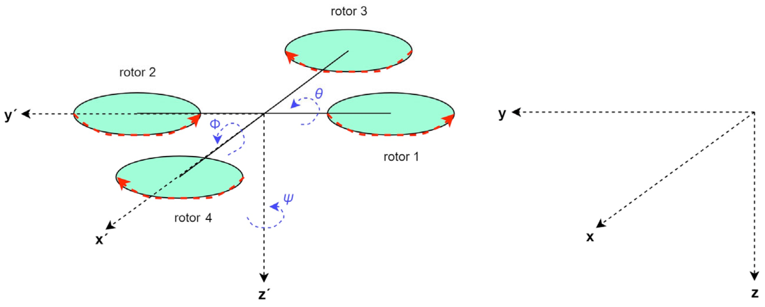
The inertial (terrestrial) coordinate system (shown in
Figure 1 as
x,
y,
z) is defined as a reference system in which Newton’s first law of motion applies. The inertial system is firmly connected to the earth’s surface. It can be oriented according to the cardinal points, or its longitudinal axis can be oriented relative to the flight path.
The aircraft coordinate system is tightly bound to the aircraft. Its origin is located at the center of gravity of the aircraft and the x-axis (longitudinal axis) is parallel to the longitudinal axis of the aircraft fuselage. The positive sense of the x-axis is towards the nose of the aircraft. The z-axis (vertical axis) makes a right angle with the x-axis and its positive direction points below the plane. The x- and z-axes determine the plane of symmetry of the aircraft. The y-axis (lateral axis) is perpendicular to the plane of symmetry of the aircraft and its positive direction points to the starboard side. Rotating around the x-axis causes a roll, rotating around the y-axis causes a pitch, and rotating around the z-axis causes a yaw, hence the names of the moments that cause them, where is the rolling moment (tilt about the x-axis), is the pitching moment (tilt about the y-axis), and is the turning moment (rotation about the z-axis).
The next step for creating a quadcopter model is the description of the action of forces, i.e., moments and thrusts, which are generated by UAV motors. Quadcopters are controlled by the angular velocities of four motors (
Figure 2). Each motor produces thrust and angular momentum, the combination of which generates the main thrust and angular momentum. To achieve the desired angular momentum, it is necessary to change the angular velocity of each of the motors. Each of the motors
creates a force
, which is proportional to the square of the angular velocity, i.e.,
[
25].
Due to the principle of operation of quadcopter motors, the produced force
is always positive. The two opposing motors always rotate clockwise and the two other motors counterclockwise. With such an arrangement, gyroscopic effects and aerodynamic moments tend to cancel out. The main thrust
u is the sum of the individual thrusts of each motor. The pitch and roll moments are always generated by different thrusts of the motors depending on the configuration of the quadcopter. The turning moment is the sum of
, where
is the reaction moment of motor
i resulting from the acceleration of the shaft and the resistance of the blades. The aerodynamic drag
can be completely derived from [
25] and, in result, it is:
Forward, backward, and sideways movements can then be achieved by increasing and decreasing the thrusts of the respective motors, depending on the configuration of the quadcopter.
Quadcopters use the changes in the thrust of individual rotors to move in space. Depending on the thrust ratio, individual rotors create torques. These moments cause a change in the orientation of the quadcopter in space [
26,
27]. However, it is also necessary to take into account the configuration of the quadcopter. Because quadcopters are symmetrical, they can fly in two different configurations, the “+” configuration and the “X” configuration. In the “X” configuration, the roll and pitch of the quadcopter are always determined by pairs of motors. In the “+” configuration, it is always only one of the motors. For each of the two configurations (+, X), the coordinate system is the same. The quadcopter will ascend and descend along the
z-axis, move forward and backward along the
x-axis, and move left and right along the
y-axis.
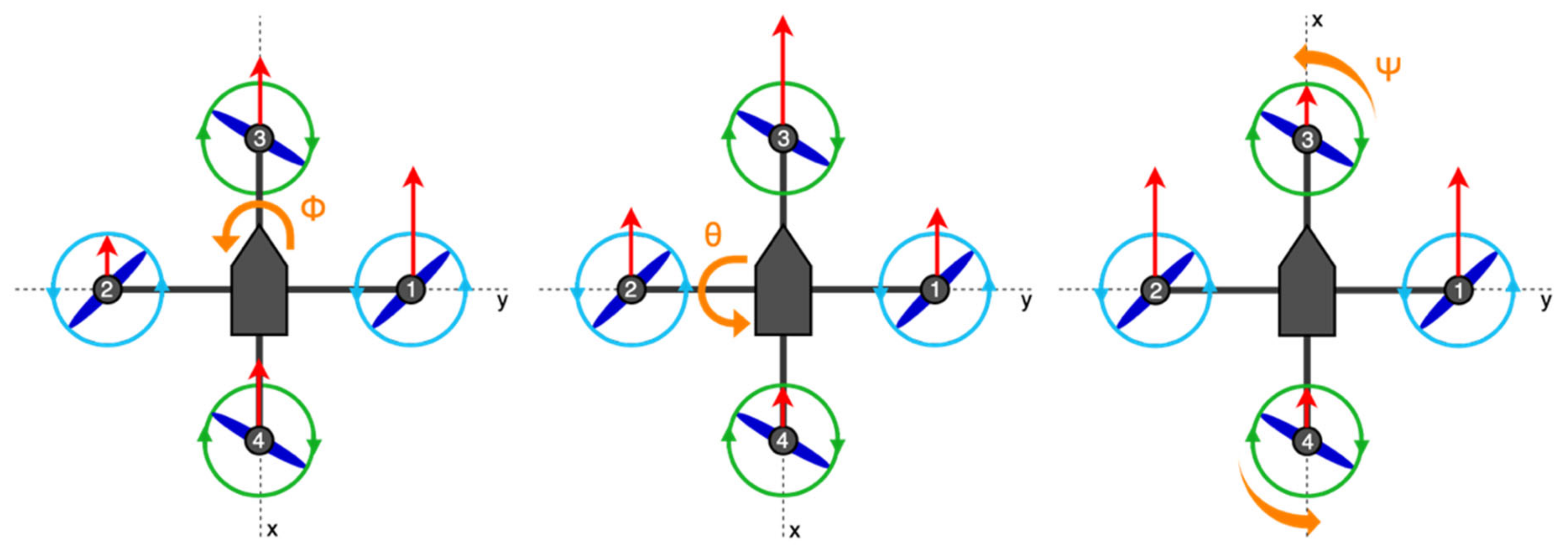
Yaw () is a rotation about the z-axis that turns the quadcopter right or left by changing the direction of flight.
Pitch () is the rotation about the y-axis that allows forward and backward flight along the x-axis.
Roll () is a rotation about the x-axis that allows right and left flying along the y-axis.
The change in the spatial orientation of the quadcopter depending on the configuration and the thrust ratio of the individual rotors is shown in
Figure 3,
Figure 4 and
Figure 5. The direction of rotation of the rotor blades is shown in green and blue, the thrust of the individual rotors is shown by the length of the red arrow, which is directed from the center of the rotor, and the direction of the resulting rotation of the UAV is shown by the orange arrow.
The moments acting on the structure of the UAV can be divided into two parts. The first part is the moments that are caused by the rotation of the rotors and the second part is the moments that are caused by the translational movement of the UAV. The rotation of the rotors creates a moment
that can cause the UAV to rotate around the
z-axis. The size of the moment
depends on the ratio and changes in the revolutions of the individual rotors. Another part depends on how the thrust is distributed between the individual rotors. The torques
and
are created by the ratio of thrusts between the rotors. A detailed description of the thrust ratios for the execution of different maneuvers for the “+” configuration and the “X” configuration [
28] is given in
Table 1.
Depending on the configuration, individual motors can therefore control thrust, pitch, roll and yaw, which is described in
Table 2.
Since, in our work, we exclusively use quadcopters in the “X” configuration, the following section will describe the mathematical derivation of the equations of the dynamic model of the quadcopter, just for the “X” configuration.
The equations of the dynamic model of the quadcopter are based on the Newton–Euler derivation. The orientation vector of the quadcopter with respect to the inertial frame is expressed as
, where
,
, and
are the Euler yaw, pitch, and roll angles, respectively. The quadcopter’s nonlinear dynamics can be expressed as:
where
D is drag,
is the rotation matrix that connects the inertial frame to the frame rigidly connected to the copter (SO(3) is a special orthogonal group),
expresses the total force acting on the copter,
is the total mass of the copter,
denotes the gravitational constant,
represents the angular velocity of the copter,
describes the matrix of inertia and
is the total moment of momentum [
25].
Let
be the force acting on the copter, which is generated by the four rotors. Assuming that this force has only one component in the
z axis direction, in that case we can write
. The rotation matrix
is defined as:
Let us define the auxiliary vector
related to the generalized angular momentum
where
and
can be expressed as [
29]:
Using Equations (2)–(5), the dynamics of the quadcopter will be expressed as follows:
In the “X” configuration quadcopter model, the M1 and M2 motors rotate counterclockwise and the M3 and M4 motors rotate clockwise. Assuming that the total thrust acts approximately to the same degree as gravity, the quadcopter will hover in one place, i.e., it will be in hover. Then, we can model the thrust of each motor as
, where
is a constant that depends on the characteristics of the rotor and
indicates the speed of rotor
[
30]. For simplicity, it is also assumed that the angular momentum
generated by each rotor is proportional to lift; therefore,
.
Taking into account the previous assumptions, we can then express the generalized moments as:
where
is the distance between the center of the copter and the center of the rotor,
CM is a constant that depends on the characteristic of the rotor, and
T is a thrust of the rotor. The final relations for the calculation of position angles can also be derived as [
31,
32,
33]:
3. Modeling of Quadcopter Characteristics
Due to the fact that we have a measurement system [
23] at our disposal that can measure UAV parameters (total thrust and thrusts of individual motors), we do not need to create a model of control and propulsion systems, and it is sufficient to create a model of the dynamics of the quadcopter. An important aspect when modeling a quadcopter is determining its parameters. With this step, we will obtain a higher accuracy of the mathematical model of the dynamics of the quadcopter. Some of the parameters can be determined experimentally (quadcopter dimensions listed in
Table 3) and some using numerical methods (moments of inertia listed in
Table 4).
Clarifying the moments of inertia of the quadcopter is important from the point of view of formulating the relations for determining the flight dynamics. There are different ways to determine these parameters, either by experimental measurement or based on theoretical numerical methods. Since the experimental methods of determining these parameters are time-consuming, we chose a numerical method for the calculation by applying Steiner’s theorem, which makes it possible to calculate the moment of inertia of a rotating body around an axis that does not pass through its center of gravity [
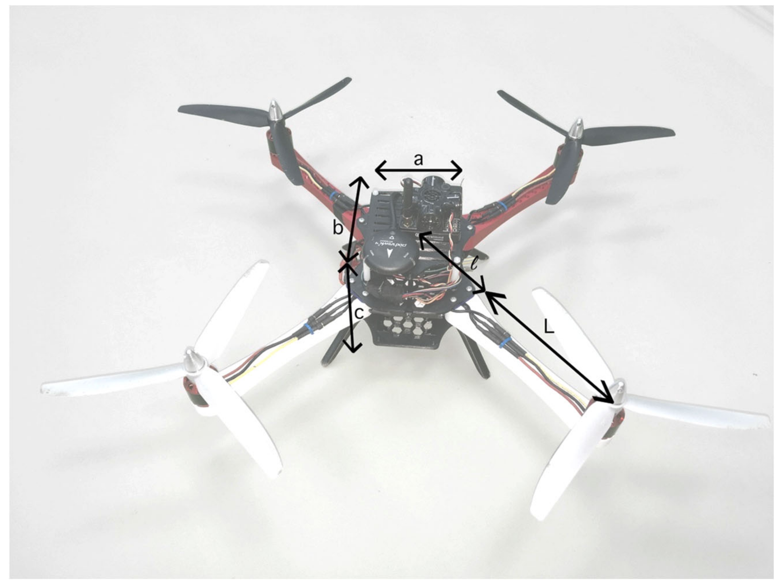
34]. In this way, for example, it is possible to calculate the moment of inertia of a body that is composed of several basic bodies, as it is enough to know the moments of inertia of individual bodies and the distance of their centers of gravity from the center of gravity of the composite body. In the case of calculating the moments of inertia for a quadcopter, we can therefore consider that the copter is a body composed of two parts. The first part is a frame in the shape of a cross, which has a defined arm length, and the second part is a central block in the shape of a cuboid with the dimensions a, b, and c.
Figure 6 describes this situation.
To calculate the moments of inertia, we derived the following relations:
where
is the total weight, which includes the weight of the battery and the weight of the central part of the quadrocopter (electronics and sensors) in the shape of a cuboid in the range from the center of gravity to
. Another variable is the weight
, which expresses the weight of the frame in the range from
to
and also the weight of the motors [
35]. The following tables give a detailed description.
These parameters are also inputs into a dynamic quadcopter model. On the basis of the given relations for calculation and on the basis of the given parameters of the copter, we calculated the moments of inertia, which are described in
Table 5.
The mathematical model of the UAV is created on the basis of relations for rotational and translational motion and relations for calculating moments of momentum [
36,
37,
38]. The main output from the model will be the position angles of the quadcopter
. The input to the copter model is the data obtained from the measurement system [
23], from the individual motors M1, M2, M3, and M4. To each of the motors correspond two tensometric force sensors in the measuring system. The values from these sensors are added up and subsequently converted to the thrust for individual motors. The copter model will consist of several subsystems in which calculations will be performed (
Figure 7).
The input to the moment calculation block is the thrusts of the individual motors, obtained from the measurement system. The calculations in this block depend on the moment equations and can be adapted to the specific configuration of the quadcopter. We know two different configurations for quadcopters, the “+” configuration and the “X” configuration. In our case, given the copter used, we worked with the equations for the “X” configuration. The outputs of the block are the individual moments around the
axes, based on which it is possible to determine the position angles of the quadcopter in the next step. In addition to the mentioned moments, we also get the total angular velocity and the total thrust of the copter at the output of this block. The structure of this block can be seen in
Figure 8.
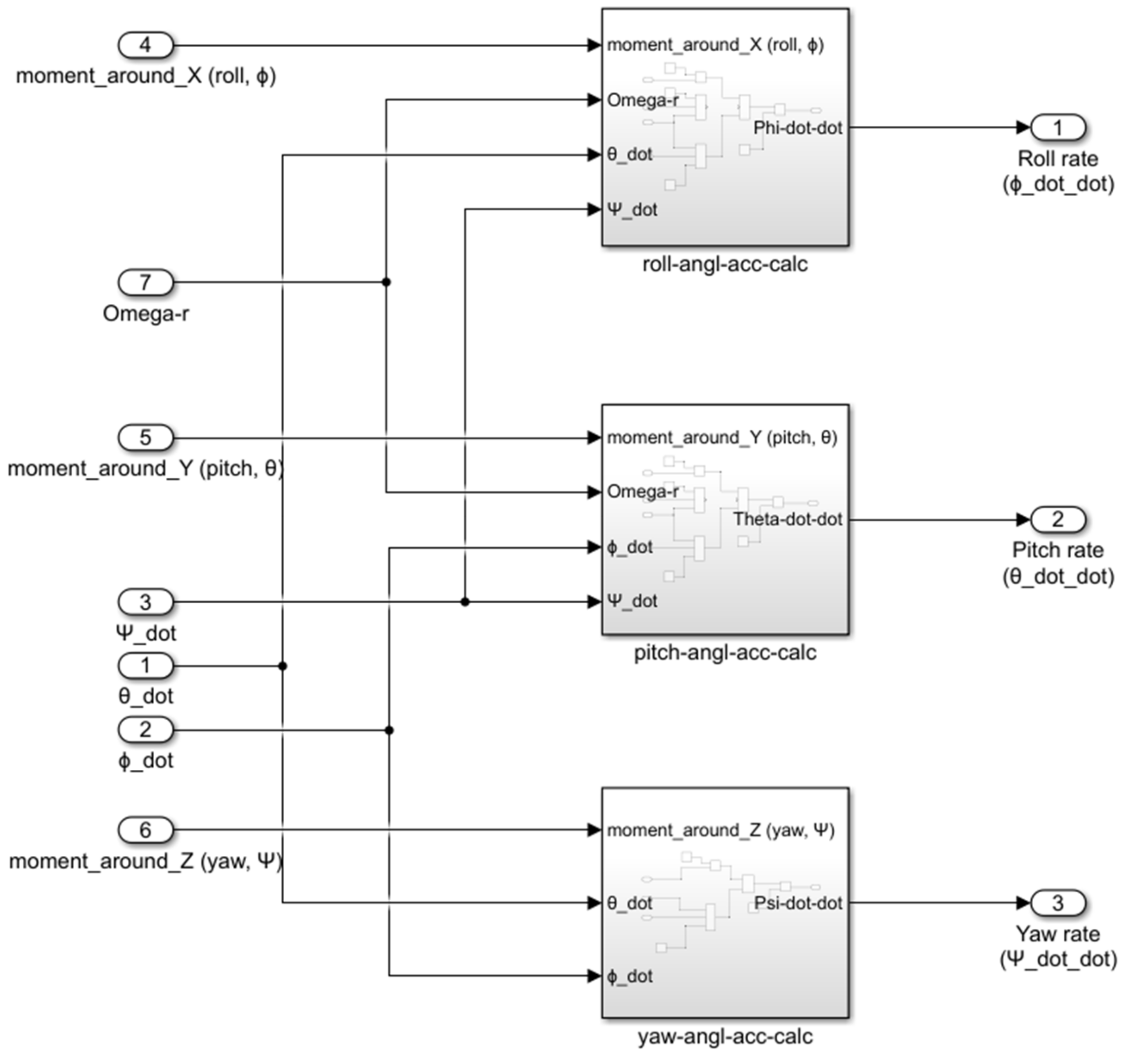
The variables U2, U3, and U4, which describe the moments around individual axes of the copter, and the variable “omega”, which determines the total angular velocity, enter the block for calculating the position angles. The structure of the position angle calculation block is described in
Figure 9.
The block for calculating position angles contains subsystems that separately recalculate the accelerations for the pitch, roll, and yaw of the quadcopter. The outputs from this block are angular accelerations, which are subsequently converted to angles by including integrators in the calculation. After creating the quadcopter model, it was necessary to verify the entire model. To verify the correct functionality of the model, we just need to apply the thrusts of the motors as the input to the model. To visualize the data, we used a Simulink Scope block in which we displayed the output for pitch (), roll (), yaw (), and height ().
Even before the actual verification, however, it is necessary to enter additional inputs which are necessary for performing the calculations. These are mainly the basic parameters of the quadcopter used, which include the total weight of the copter, the length of the copter arm, and individual moments of inertia (
Table 3,
Table 4 and
Table 5).
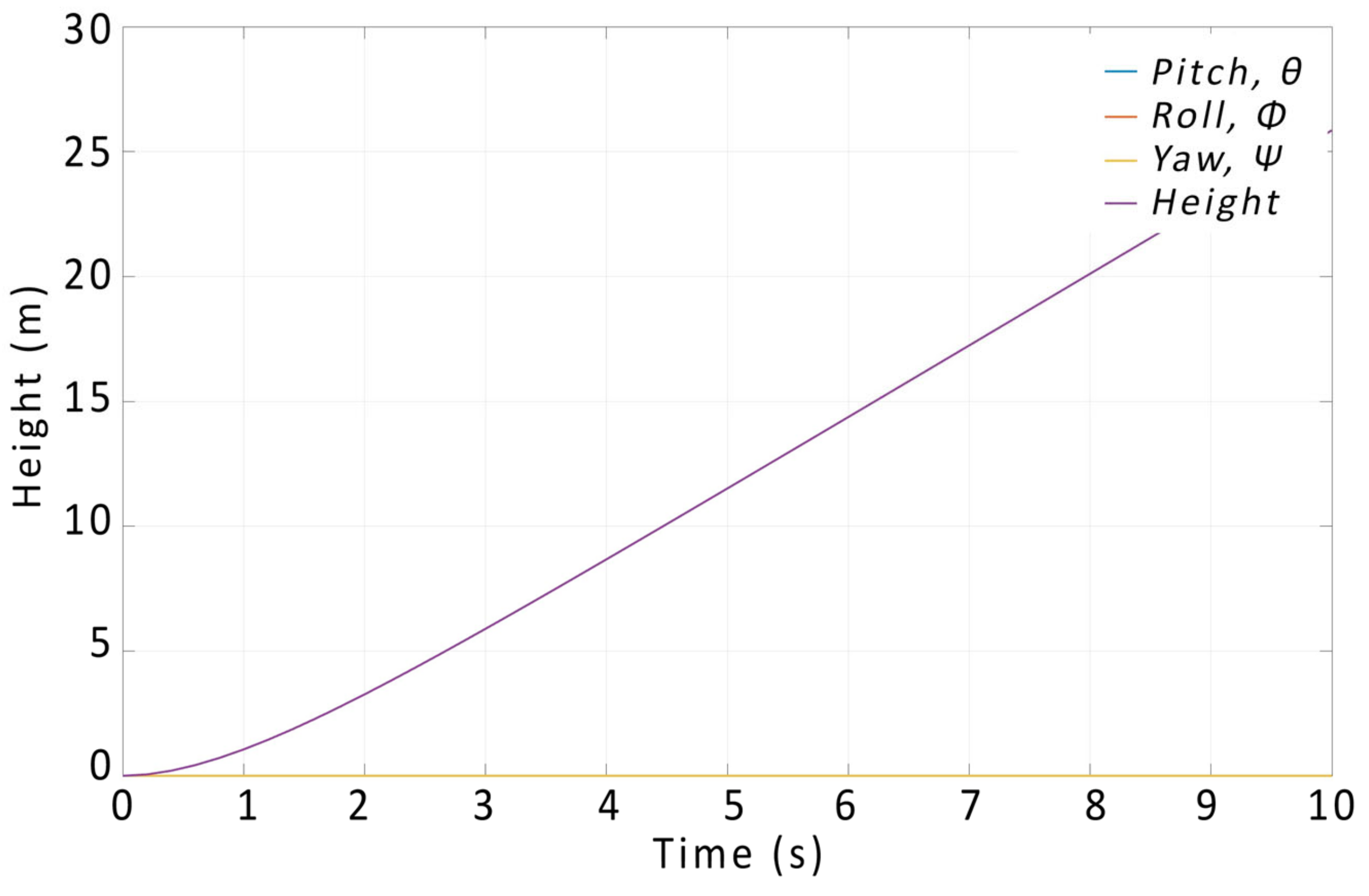
In the first step, we set the same thrust for each of the motors at each input to the model. The output from the model with such settings is shown in
Figure 10, where after setting the same thrust value for each of the motors, the height value changes at the output of the model, i.e., the quadcopter tends to rise. The values of the position angles
do not change and are zero, from which we can conclude that the first of the calculations works correctly.
In the next step, it is necessary to verify whether the calculations for the position angles
respond correctly. This can be verified by applying different thrust values at the input to the model. During the verification, we will start from
Figure 4 (or
Table 1), which shows the thrust ratios of the individual motors for performing the required maneuver.
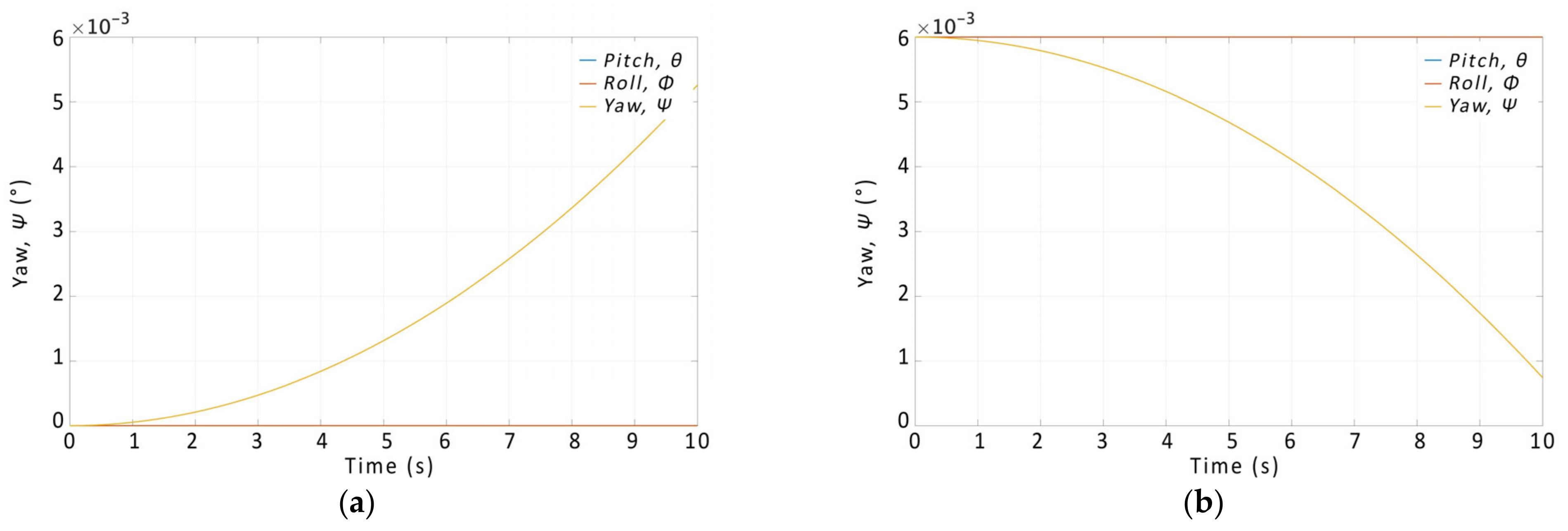
To verify the functionality of the model for the roll mode, in the first step we have set an increased thrust at the input of motors M1 and M4, and the thrust on motors M2 and M3 was reduced, which should have been reflected by a roll to the left. In the second step, we reversed the ratios between the pairs, which should have rolled the quadcopter to the right. The resulting output graphs are shown in
Figure 11. Similarly, we verified the model for the pitch and yaw of the quadcopter, as shown in
Figure 12 and
Figure 13.
Based on the output curves, it can be concluded that the proposed model works correctly and the relations for the calculations were derived correctly.
To be able to model flight characteristics based on static laboratory measurements, it is necessary to input the measured thrusts from the measurement system into the model and then introduce feedback from the model of the copter’s dynamics into the FC. We implemented the feedback system using a servo platform with a PID controller, on which the flight controller unit can be placed [
39]. The platform works by tilting the FC based on the motor thrusts and the modeled response, thus simulating realistic accelerations and rotations for the flight controller sensors. By such introduction of feedback, the servo platform turns the flight controller unit to the desired position, given the recalculated position angles at the output of the copter dynamics algorithm, which was described in previous research [
39]. The PID constants for the servo platform were obtained from the FC of the tested quadcopter, so its reactions could be observed in the modeled and simulated environment.
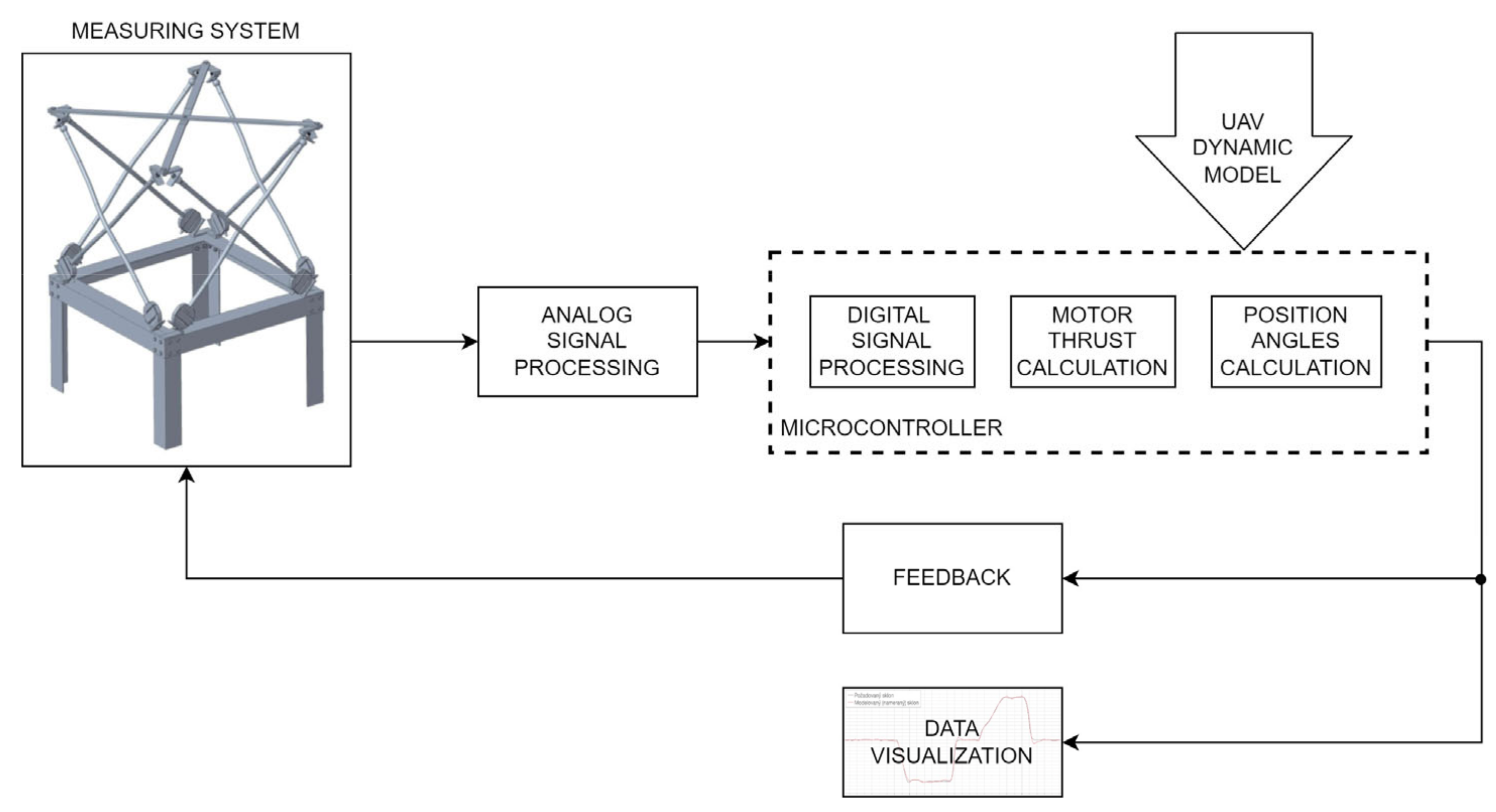
After introducing feedback into the measurement system, we performed measurements focusing on the desired deflection and the measured deflection, which is the output of the copter’s dynamics model. The measurement chain is shown in
Figure 14. During the measurement, we used the NUCLEO H743ZI microcontroller (Madrid, Spain), which has a 16-bit A/D converter. During the measurement, the drone was attached to the measurement system, which is shown in
Figure 15.
4. Results
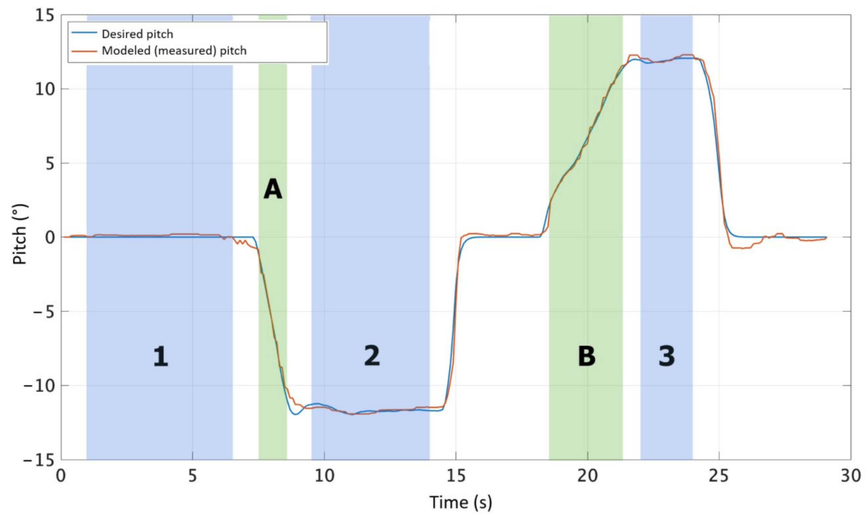
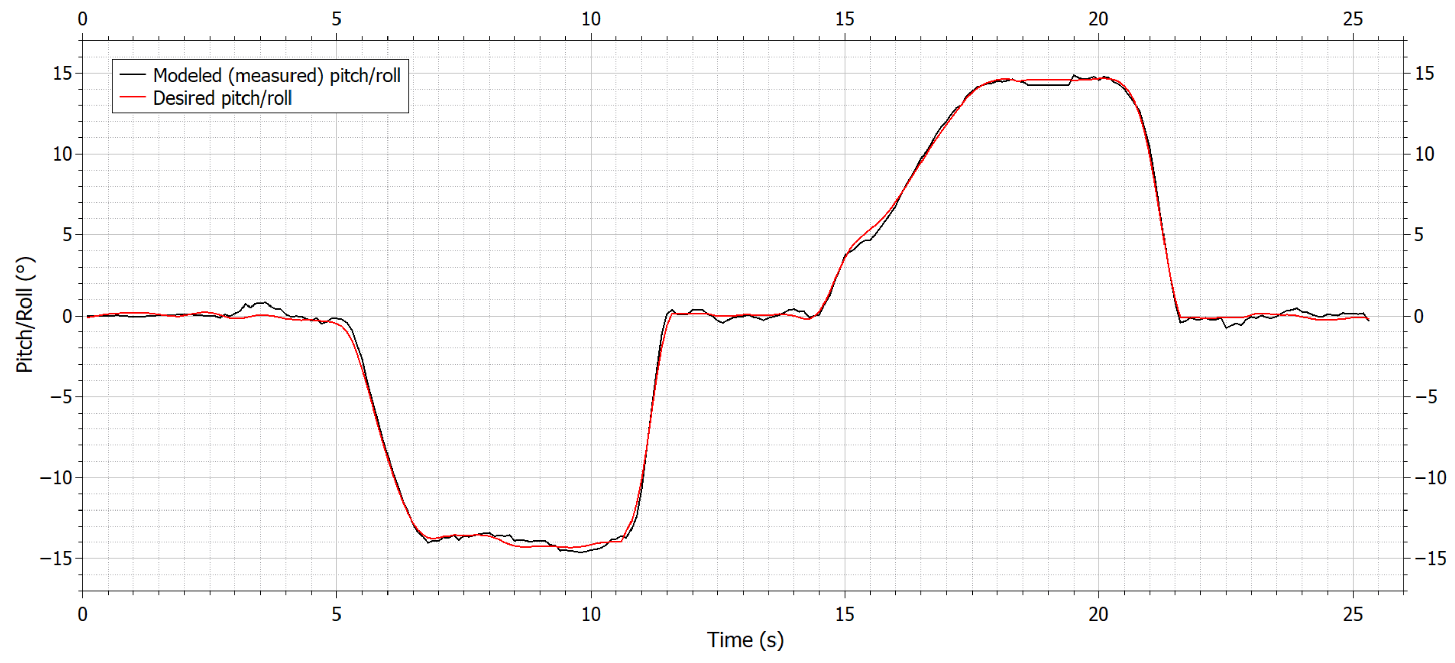
The measurement process took place via the operator setting the required deviation of the pitch angle on the controller. Given the desired angle, the individual UAV motors began to produce thrust, which was measured using the UAV parameter-measurement system. The thrust measured this way was then fed to the input of the dynamic model, where a recalculation was made based on the thrust ratio for the simulation of position angles. The measured and simulated characteristic is shown in
Figure 16.
According to the measured curves, the operator set the required angle to a value of approximately −12° in the first step, the modeled (measured) angle also reached a value of approximately −12°. In the second step, the control stick was set to the central position, i.e., the required and measured angle was 0°. In the last step, the desired angle was approximately +12°, and the measured values were also approximately 12°. For testing the roll axis, the results are the same, as the quadcopter is symmetrical along the two horizontal axes, and the PID controllers also use the same constants. Since quadcopters have less authority along the yaw axis compared to the pitch and roll axes, those measurements were not deemed crucial in this phase, but will be conducted in further research.
Overshoots that can be observed when quickly returning to the 0° position (especially at the end) may be caused by the use of a TEMA filter when measuring the thrusts of individual motors, or by setting the PID controller. Considering this fact, it is possible to solve the problem of tuning UAV control algorithms through future optimization based on the characteristics modeled in this way. If, for example, the weight of the quadcopter changes, it manifests itself in the modeled characteristics, which can be used to fine-tune the PID controller constants.
When evaluating the measurement, we compared the deviations between the required data and the measured data, which are the output of the quadcopter dynamics model (according to the curves in
Figure 16). The results are described in
Table 6.
When evaluating the accuracy of the model, we also focused on the MAAE (maximum absolute error), MAE (mean absolute error) and MAPE (mean absolute percentage error) [
40,
41]. We calculated errors for stable parts of the characteristic (blue parts) and for selected parts of the characteristic where there was a change in deviation (green parts), according to
Figure 16. The calculated results for individual parts of the characteristic are shown in
Table 7.
Considering the mentioned values, we can state that the calculated errors did not exceed the limit of 1% in any case. Based on this, it can be concluded that the accuracy in modeling the characteristics of the quadcopter based on static laboratory measurements, using the designed measurement system and the model of the dynamics of the quadcopter, is more than 99%.
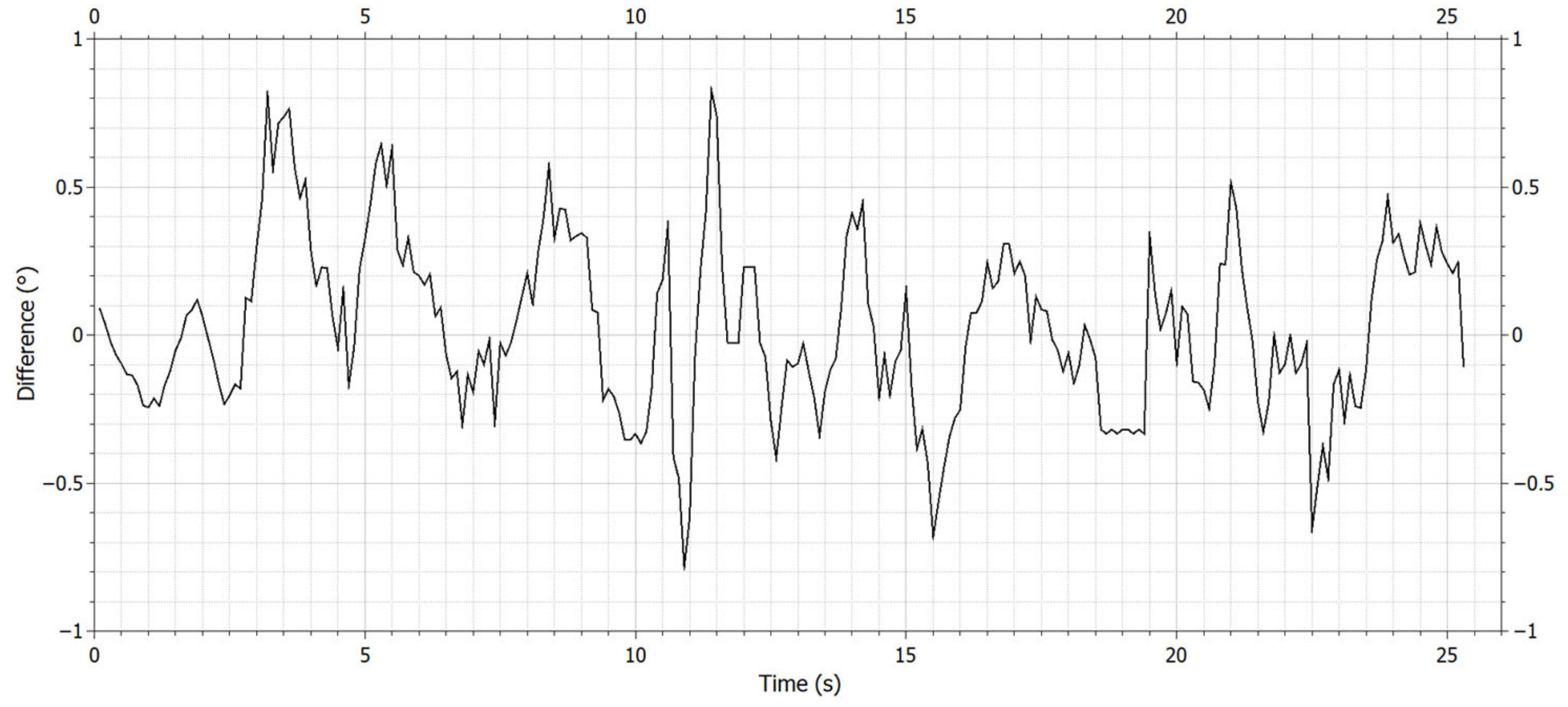
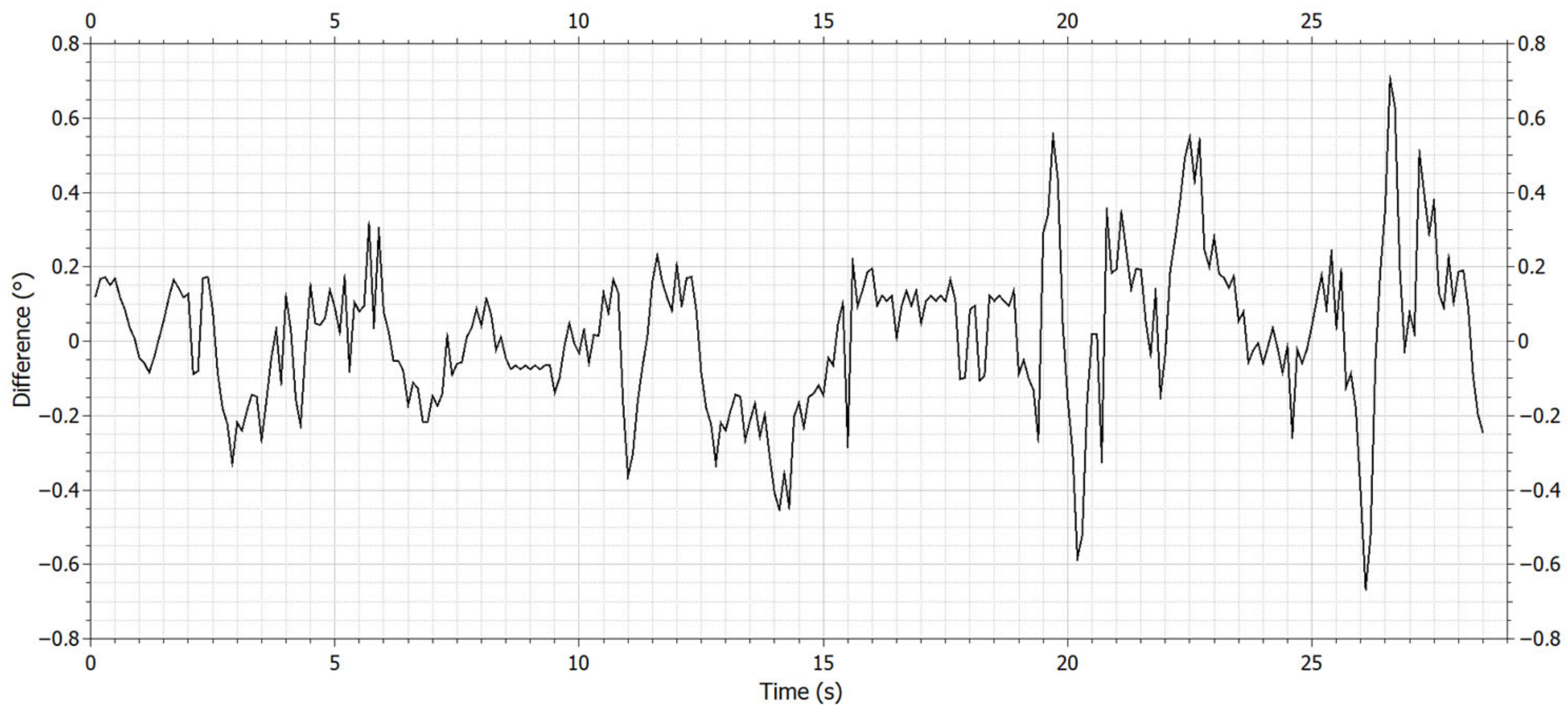
For verification, we added two more measurements with a quadcopter, but the weight of the payload was increased by 100 g (
Figure 17 and Figure 19) and the constants of the PID controller were the same. The results are similar to those in
Figure 16. Differences between the desired and modeled pitch/roll are shown in
Figure 18 and Figure 20.
5. Discussion
UAV parameter modeling is currently the subject of various research. Emphasis is mainly placed on tuning UAV control algorithms and reducing the time required for tuning PID controllers. This can be achieved by using the designed measurement system [
23] and implementing the mathematical model of UAV dynamics into this system. The main benefits of the given method of UAV dynamics modeling are a specific technical solution and a new method that allows measuring the parameters and modeling the characteristics of unmanned vehicles, based on static laboratory measurements, without knowing the model of the specific motors used on the UAV. The advantage of this method is that the unmanned vehicle is firmly connected to the measurement system. The output of the measurement system is the parameters of the unmanned vehicle, i.e., the thrusts of the individual motors. The measured thrusts enter the mathematical model of UAV dynamics, where they are subsequently converted to position angles. The obtained dynamics model can be used for the tuning and optimization of UAV control algorithms. The implemented technical solution allows the theoretical use of this method for any four-rotor UAV weighing up to 40 kg, due to the working range of the sensors used in the system. The proposed method is especially beneficial from the point of view of optimization of the control algorithms of UAV flight stabilization. The method reduces the time-consuming optimization of the control algorithms, as it allows corrections of the control electronics to be made in the future without the need to perform a test flight.
However, the accuracy of the measurement and calculations also depends on the A/D converter used. It is advantageous to use a converter with a higher resolution, which increases the accuracy of the simulation and modeling. In modeling, we used a microcontroller with a 16-bit converter, which brought the resolution of the measurement system to the level of 0.4637 g/bit (so the resolution of one sensor is 0.0579625 g/bit). With such a resolution, the error of the measuring system was limited to ±0.4637 g.
In this article, the parameters of the used quadcopter were determined and the procedure for calculating these parameters was given, and a mathematical model of the dynamics of the UAV was also created, along with the verification of its functionality and the subsequent introduction of feedback from the model back into the measurement system. Based on this model, an algorithm for calculating the position angles and coordinates of a UAV in three-dimensional space was created and implemented in the microcontroller. In the end, a verification measurement was carried out, aimed at modeling the characteristics of the quadcopter, along with an evaluation of accuracy.
The potential for further development in the given area is mainly in the modification of the software, the implementation of the algorithm for the automated calculation of the constants of the control electronics regulators, and the implementation of neural networks in the calculation. In addition, it is possible to create a custom GUI solution in the future, which will, among other things, provide several options, from the calculation of the copter’s parameters to the visualization of the measured data and their evaluation. These topics are the subject of our further research and development in the area of UAV modeling.
