1. Introduction
Recently, significant progress has been made in unmanned aerial vehicle (UAV) technology, demonstrating its unique advantages in various fields [
1,
2,
3]. Quadrotor UAVs, in particular, have been widely used in diverse application scenarios due to their excellent adaptability to environmental changes [
4,
5,
6]. However, in practical applications, one important technical challenge with quadrotor UAVs when performing payload-carrying tasks is the swing of the payload [
7,
8,
9,
10]. This swing not only affects the flight stability of the UAV but also risks damaging the cargo and potentially endangering the UAV’s safety [
11,
12]. Therefore, researching methods to effectively suppress the payload swing of quadrotor UAVs and enhance the efficiency and safety of transportation has significant theoretical and practical value [
13,
14].
The quadrotor UAV transportation system is particularly suitable for carrying payloads with high uncertainty. However, this system is complex, featuring multiple degrees of freedom, strong coupling, and underactuation. The quadrotor UAV has six degrees of freedom but only four control inputs. During the operation of the transportation system, the suspended payload further increases the system’s underactuated characteristics. Additionally, the quadrotor UAV, the payload, and the cable connecting them are tightly coupled, with complex interactions between their relative displacements and attitude angles, which undoubtedly exacerbates the overall control difficulty of the system. These complexities pose significant challenges in the design and implementation of control strategies for the quadrotor UAV transportation system.
To address these issues, various controllers have been developed. Reference [
15] designed a nonlinear model predictive controller for the simplified dynamic model of a quadrotor UAV payload. In [
16], a control design using the nested saturation method was proposed. In reference [
17], aerodynamic parameters were identified online using a Kalman filter, followed by rotor speed compensation with an LQR strategy, which significantly improved the quadrotor’s control performance in heading and altitude. These studies typically simplify the quadrotor’s nonlinear dynamics into linear models for mathematical convenience, although this may introduce approximation errors and limit performance. In [
18], a nonlinear control method based on energy analysis is proposed, which achieves simultaneous localization and elimination of payload oscillation for a quadrotor UAV. In [
19], a virtual control input was designed for the outer-loop subsystem using an energy-based analysis method. Ultimately, the stability of the closed-loop system was proven based on the LaSalle’s invariance principle. In [
20] a mathematical model and control strategy suitable for quadrotor UAV transportation systems are proposed, achieving robust control under parametric uncertainties and unmodeled dynamics, as well as precise delivery and swing reduction control for the payload.
In the practical application of the quadrotor UAV transportation system, simplifying the cable connecting the UAV to the payload as a rigid body model is not realistic. During actual flight, due to the relative motion between the UAV and the payload, the cable will undergo elastic deformation, leading to uncertainty in the changes of the cable length. This uncertainty can not only affect the coordinate position of the payload but may also interfere with the system’s energy function. When controlling the quadrotor UAV transportation system, this uncertainty can reduce control precision and stability, and may even lead to system instability. Therefore, in order to ensure the safe and efficient operation of the UAV transportation system, it is necessary to thoroughly study the issue of unknown cable lengths and propose corresponding solutions.
An in-depth study of flexible cables in transport systems has been carried out in [
21], where each cable is treated as a system of links connected in series and a geometrically nonlinear controller has been designed to enable the precise transport of a rigid body to a predetermined position and to keep all the links aligned in the vertical direction. In [
22], a novel bidirectional fuzzy brain emotional learning controller is proposed, which enables precise trajectory tracking for quadrotor UAV in the presence of payload uncertainties.In the referenced documents [
23,
24], the authors addressed the issue of cable length discrepancies within the system and engineered an adaptive control mechanism to enhance the fidelity of the control scheme. References [
25,
26] incorporate the cable length into their control strategies. Nevertheless, the swing angles of the payload are not taken into account during the control design process, which may result in reduced performance in anti-swing control measures.
To ensure the precision and stability of the quadrotor UAV transport system, this paper has delved into the problem of anti-swing control and the elastic deformation of the cable. We have developed an adaptive controller that integrates energy functions with barrier Lyapunov functions. This paper addresses the non-linear and underactuated characteristics of the quadrotor UAV transportation system, aiming to achieve precise position control and anti-swing capabilities. Precise position control and effective anti-swing management of the quadrotor UAV suspension transportation system enhance the overall stability and safety of the system, which is crucial for the operation of the UAV and the safety of the payload. Unlike the Lagrange modeling approach used in [
23], this paper employs the Newton-Euler method for force analysis in dynamic modeling, which obviates the need for subsequent additional force analysis on the cable. Furthermore, in the design of the controller, this paper introduces an integral barrier Lyapunov function to describe the nonlinear constraints of the system, thereby further enhancing the stability of the system.
The improved precision in control capabilities enable quadrotor UAVs to perform more complex and delicate tasks, such as cargo transportation, aerial rescue, and environmental monitoring in high-altitude or hazardous areas. The adaptive control design ensures that the system maintains good control performance in the face of uncertainties such as unknown cable length, enhancing the system’s autonomy and robustness.
The main innovations and contributions of this research can be summarized as follows:
The paper employs an energy-based approach to successfully achieve anti-swing control of the quadrotor UAV transport system while carrying a payload.
By utilizing barrier Lyapunov function to describe the system’s non-linear constraints, the controller’s performance is further optimized, and a double-closed-loop nonlinear controller is designed to achieve stable control of displacement and attitude angle.
Through the application of adaptive estimation, the length of the cable can be adjusted in real-time, thereby significantly improving the control accuracy of the quadrotor UAV transport system.
The control stability of the quadrotor UAV transport system has been comprehensively verified by the Lyapunov theory and the LaSalle’s invariance theorem.
The structure of this paper is as follows: In
Section 2, the dynamical model of the quadrotor UAV transportation system is introduced in detail.
Section 3 delves into the design of controllers based on the energy method and the obstacle Lyapunov function, and the asymptotic stability of the control system is proven using the Lyapunov theory and LaSalle’s invariance theorem.
Section 4 presents the results of simulation experiments. Finally, in
Section 5, we summarize the main conclusions of this paper.
2. Dynamic Model of the Quadrotor UAV Transport System
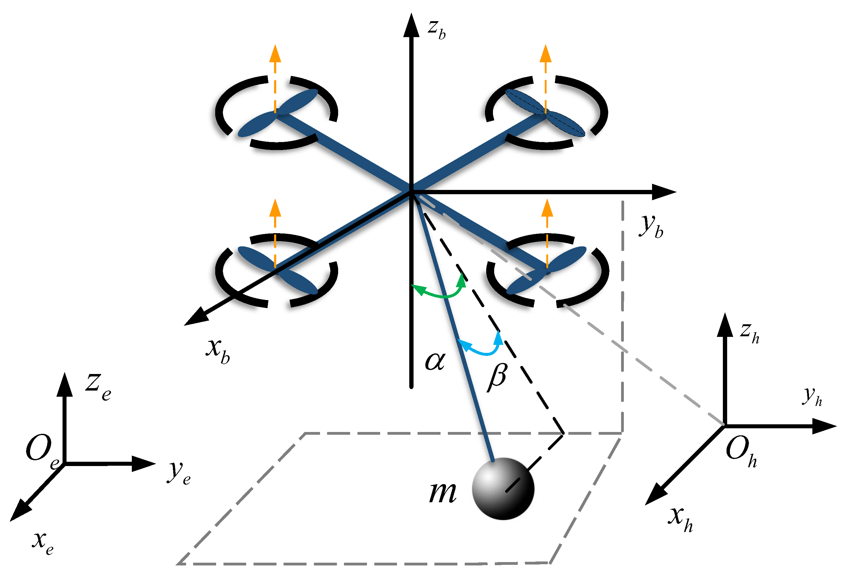
A quadrotor UAV transport system consists of a quadrotor UAV, a cable, and a suspended payload, as shown in
Figure 1. In order to describe the attitude and position information of the quadrotor UAV with the suspended payload more accurately, three coordinate systems are established, namely: the inertial reference frame
, the body reference frame
, and the payload reference frame
.
The rotational matrix from
to
is indicated by
as shown below:
where
and
are sin(i) and cos(i) abbreviations, respectively. And the rotation matrix from
to
is indicated by
as shown below:
The motion of the quadrotor UAV transport system can be accurately represented by two different vectors. Firstly, the vector of translational motion represents the position of the system in the three-axis direction with respect to the inertial reference frame. The second is the vector of Euler angles , which describes the three Euler angles of the system. The positional information of the payload is represented by two swing angles and . The masses of the UAV and the payload are denoted by M and m, respectively, and the tension and length of the sling are denoted by T and L, respectively.
Unification of forces in different reference frames in the quadrotor UAV transport system based on the above rotation matrices.
where
and
represent the forces on the system in
and
, respectively. And
is represented as the Euclidean norm of
. The specific expression of
is:
And the forces
in
can be obtained:
The specific expression of
is:
The positional relationship between the quadrotor UAV and the payload can be represented as:
where
is the position of the payload,
is the position of the UAV, and
.
The forces on the UAV can be described as:
where
, and
g is the acceleration of gravity. And the force analysis for the suspended payload is as follows:
According to Equations (7)–(9), a specific expression for the tension
can be obtained:
where
, and
.
Through the Newton-Euler method, the UAV transport system is analysed in terms of forces, and then after unifying the reference frame, the dynamic equations of the system in the inertial reference frame
can be obtained as follows:
where
is an auxiliary vector.
In the quadrotor UAV system, in order to adjust its attitude angles, the speeds of the individual rotors are typically adjusted to generate an unbalanced torque. This torque enables the UAV to rotate around an axis perpendicular to its body, thereby changing its orientation.
Based on this, the dynamic model of the quadrotor UAV’s attitude can be described as:
where
3. Control Scheme Design
In this section, an in-depth analysis of the energy characteristics of the quadrotor UAV transportation system has been conducted, and a design scheme for a nonlinear anti-sway controller based on the energy method has been proposed. In addition, the control scheme also meticulously considers the issue of cable length changes due to elastic deformation, thus incorporating this key factor into the control strategy of the quadrotor UAV transportation system. The design of the system is based on assumptions, which are presented in the
Appendix A. Through this design, it is possible to control the swing of the UAV during payload transportation more accurately, ensuring system stability and transportation efficiency.
3.1. Construction of Energy Functions
This section is dedicated to the design of an anti-swing reduction control scheme for the quadrotor UAV transport system. Addressing the issue of underactuation in the suspended payload, an energy function is constructed to describe the relative motion state between the UAV and the payload, ensuring stable control of both the UAV’s movement and the suppression of the payload’s swing angle. Furthermore, considering the unknown elastic deformation length of the cable, an adaptive control design is proposed.
Considering the mechanical energy
of the quadrotor UAV transport system, which comprises both the system’s kinetic energy and potential energy. The kinetic energy of the quadrotor UAV can be defined as:
Taking the derivative of Equation (
14) with respect to time results in.
The kinetic and potential energy functions of the payload can be defined as:
Taking the derivative of Equation (
16) with respect to time results in.
To describe the subsequent control design and stability analysis more clearly, the following auxiliary signals
,
are defined as:
where
is the displacement error of the UAV, and
is the target position coordinate of the UAV, and its derivative with respect to time is zero. In Equation (
18),
and
are two diagonal positive definite gain matrices.
To achieve more precise control over the UAV’s flight performance, the total thrust generated by the UAV must be skillfully decomposed into two components: a force
parallel to the cable, and a force
perpendicular to the cable. The primary role of
is to counteract the weight of the payload and correct positional deviations in the flight path, while
is dedicated to minimizing the swinging motion of the payload, ensuring overall stability and operational accuracy. The specific expression for
is:
In Equation (
19),
is used as an estimate for the unknown length of the cable. Meanwhile, the estimation error of the cable length can be defined as
, and an adaptive update law can be designed as follows:
where
is a positive constant, and the function
is defined as:
The controller for the quadrotor UAV transport system is designed with non-linear constraints arising from the UAV’s state equations and dynamic characteristics. To improve the controller’s performance and ensure the UAV’s stable operation under these non-linear constraints, barrier Lyapunov functions are utilized in the controller design process.
Lemma 1. The function , defined with respect to the system within an open interval D containing the origin, is considered a barrier Lyapunov function if it meets the following conditions: 1. is continuous and differentiable within the interval D. 2. is positive-definite within the interval D. 3. As x approaches the boundary of the interval D, . 4. For all and for any initial condition , there exists a positive number b such that the solution of satisfies for all t.
The design of the integral barrier Lyapunov function is as follows:
where
represents the constraint range, and
,
represents state constraints.
Based on the constructed energy function of the quadrotor UAV transport system and the designed integral barrier Lyapunov function, the Lyapunov function is designed as:
The derivative of time can be obtained by taking the derivative of time for both sides of
at the same time.
To ensure that
, it is only necessary to design a controller such that:
By organizing the specific expression of
T from Equation (
10) and the relationship between
and
from Equation (
6), we can obtain:
The expression for the controller can be obtained by organizing Equation (
26):
where Equation (
27) is an implicit equation, as shown in Equation (
6), where
is a function of
and
. And
,
, and
are auxiliary quantities, and their specific expressions are:
From the design of the energy function, it is evident that and respectively determine the emphasis placed on the UAV’s position and the swing of the suspended payload within the controller. This means that as the difference between and increases, the influence of the “anti-sway action” within the controller becomes more significant, while if this difference decreases, its impact diminishes accordingly.
Define the attitude angle errors
, where
represents the desired attitude of the quadrotor UAV. Drawing from the dynamic model of the attitude angles (Equation (
12)) and considering the attitude angle errors during the UAV’s flight, we have designed a nonlinear attitude angle controller.
where
,
,
are all control gains.
As shown in
Figure 2, this is the double closed-loop nonlinear control scheme designed in this paper. The controller integrates energy-based methods and integral barrier Lyapunov functions, achieving precise closed-loop control of the position and attitude angle for the quadrotor UAV transportation system.
3.2. Stability Analysis of Controller
Theorem 1. The quadrotor UAV suspension system described by Equation (11) can effectively achieve the gradual approach of the UAV’s position to a predetermined target point through the controller designed in Equation (27). During this process, the swaying angle of the suspended load is also effectively controlled to ensure that the system stably converges to a balanced state such that Proof of Theorem 1. The Lyapunov function can be designed as:
□
By substituting Equation (
27) into Equation (
32) and organizing the result, we can obtain:
According to the previous Equations (20) and (21), the following inequality can be obtained.
Thus, it can be concluded that
From the above results, it can be concluded that , and based on the fact that , , , , it can be inferred that they are bounded. By utilizing the conclusion that , it can be derived that . Then, due to the boundedness of and the unit vector , it can be concluded that . Given the boundedness of and , it can be inferred that . Based on this inference, we can conclude that all signals in the quadrotor UAV transportation system are bounded.
Given the boundedness of all state variables, the Barbalat’s lemma can now be employed to prove Theorem 1. For this purpose, the set
is defined as follows:
Lemma 2. By Barbalat’s theorem, assuming that there exists a function which is uniformly continuous in and that there exists , a limit exists.
According to Equation (
32):
is bounded according to Equation (
37). Similarly, this also means that the other state quantities are also bounded.
From Equations (32) and (35), there exists
, that is,
is bounded. Integration of Equation (
35) can be obtained:
From Equation (
38), it can be obtained that:
It can be obtained from Equation (
39):
According to Equations (35), (40) and Lemma 2 the following can be obtained:
And Equation (
11) can be rewitten as:
Equation (
42) can be regarded as an equation system involving
,
,
, and by solving this equation system, the specific mathematical expressions for
,
,
can be obtained:
The result can be obtained by substituting Equation (
43) into the designed controller (27):
Take the time derivative of both sides of Equation (
44), since
,
,
, the following expression can be obtained:
Then we intend to employ the method of proof by contradiction to demonstrate that
,
. We assume that within some subset of set
, there exists a point that does not satisfy the condition of having
,
. Based on Assumption 1, we find that
,
. Furthermore, the outcome of Equation (
40) clearly leads to the following conclusion:
Based on Equation (
46), we can derive the following equation:
The conclusion of Equation (
48) conflicts with the assumption that there exists a point in set
such that
,
. Therefore, it can be inferred that the point in set
does not actually exist, and thus
,
in set
. And is also
,
,
,
. Substitute the above result into Equation (
36):
Based on Equations (26) and (49), it can be obtained that:
According to the Barbalat’s lemma, prove that , , , , , and in the quadrotor UAV transportation system all asymptotically converge to the equilibrium point.
Consider a Lyapunov function candidate for attitude angle control:
Taking the derivative of Equation (
10) with respect to time results in.
Replacing Equation (
30) in (52), it can be organized as:
By Equation (
53), it indicates that
, and the state variables of the system
,
,
. The case
only occurs when all the state variables are all equal to zero at the same time, so we can prove that the attitude loop subsystem can be asymptotically stable by (53).
4. Results
In this section, to evaluate the control performance of controller 27 for the quadrotor UAV transportation system, numerical simulations were carried out for position control and anti-swing control. A comparison was also made with a nonlinear antiswing control method in [
27] and the LQR control method in [
28], highlighting the superiority of this control strategy.
The desired attitude of the quadrotor UAV is provided by the position loop control strategy, while the required yaw angle is given by the navigation system.
The system parameters are as shown in
Table 1.
The designed comparative controller is:
The gains of the controller are selected as:
The simulation experiment was divided into three groups, in Case 1 Position Control, the primary focus is on conducting a comparative analysis of different control strategies in terms of their dynamic performance in system displacement control. Case 2 Anti-swing Control emphasized the comparison of the impact of these control strategies on the dynamic performance of system payload swing angle control. Case 3 Robust Control is centered on the evaluation of the robustness performance exhibited by various control strategies.
4.1. Case 1: Position Control
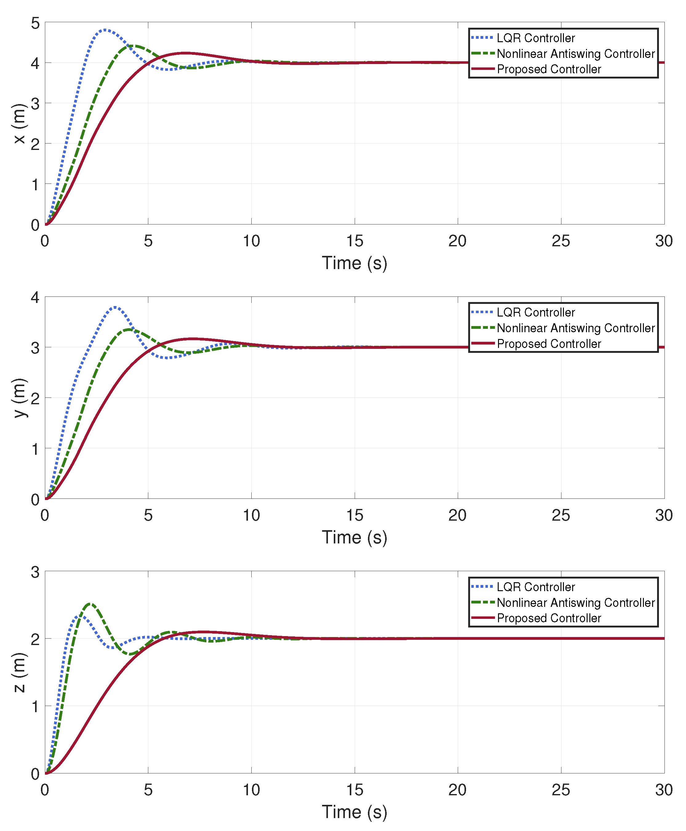
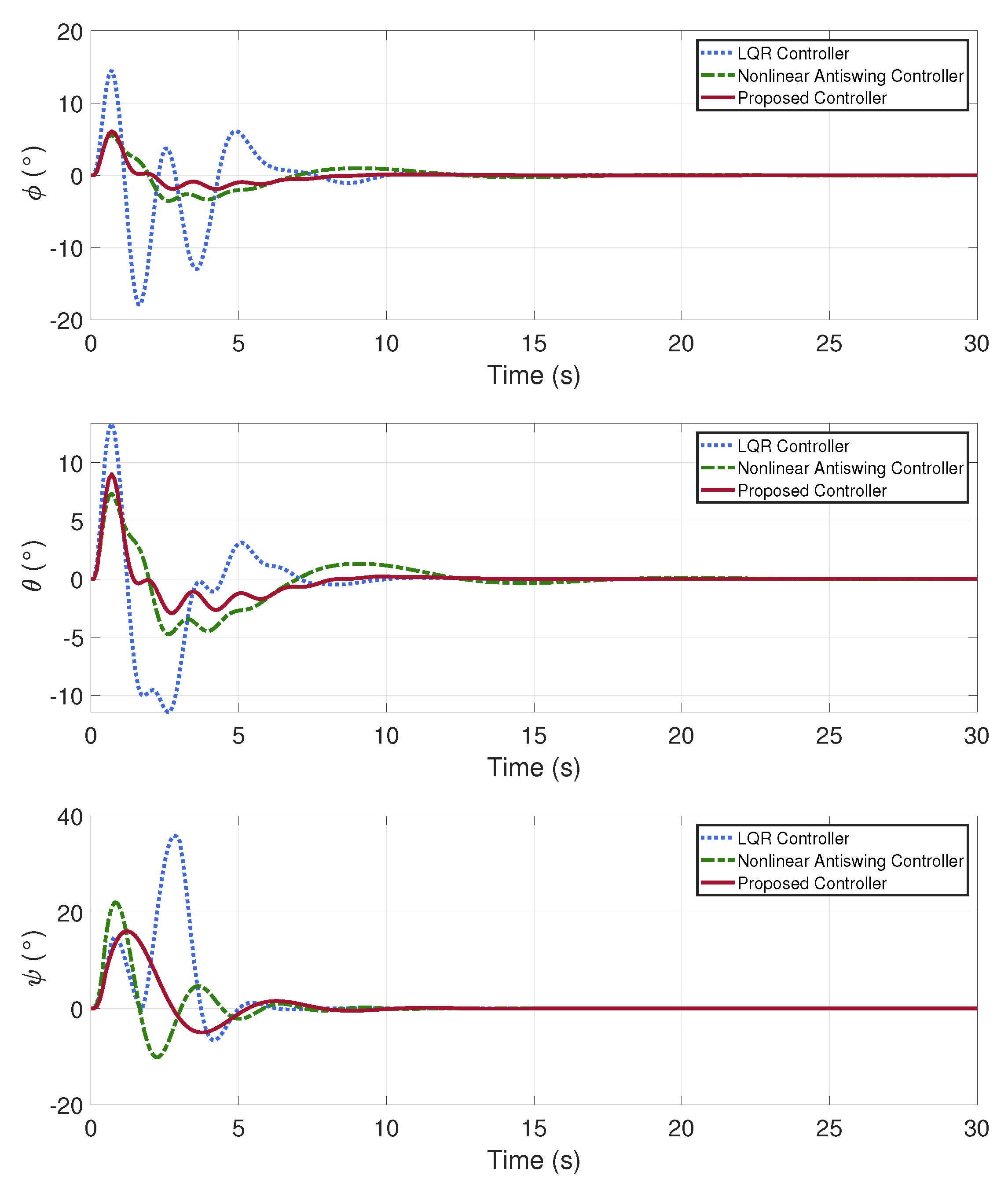
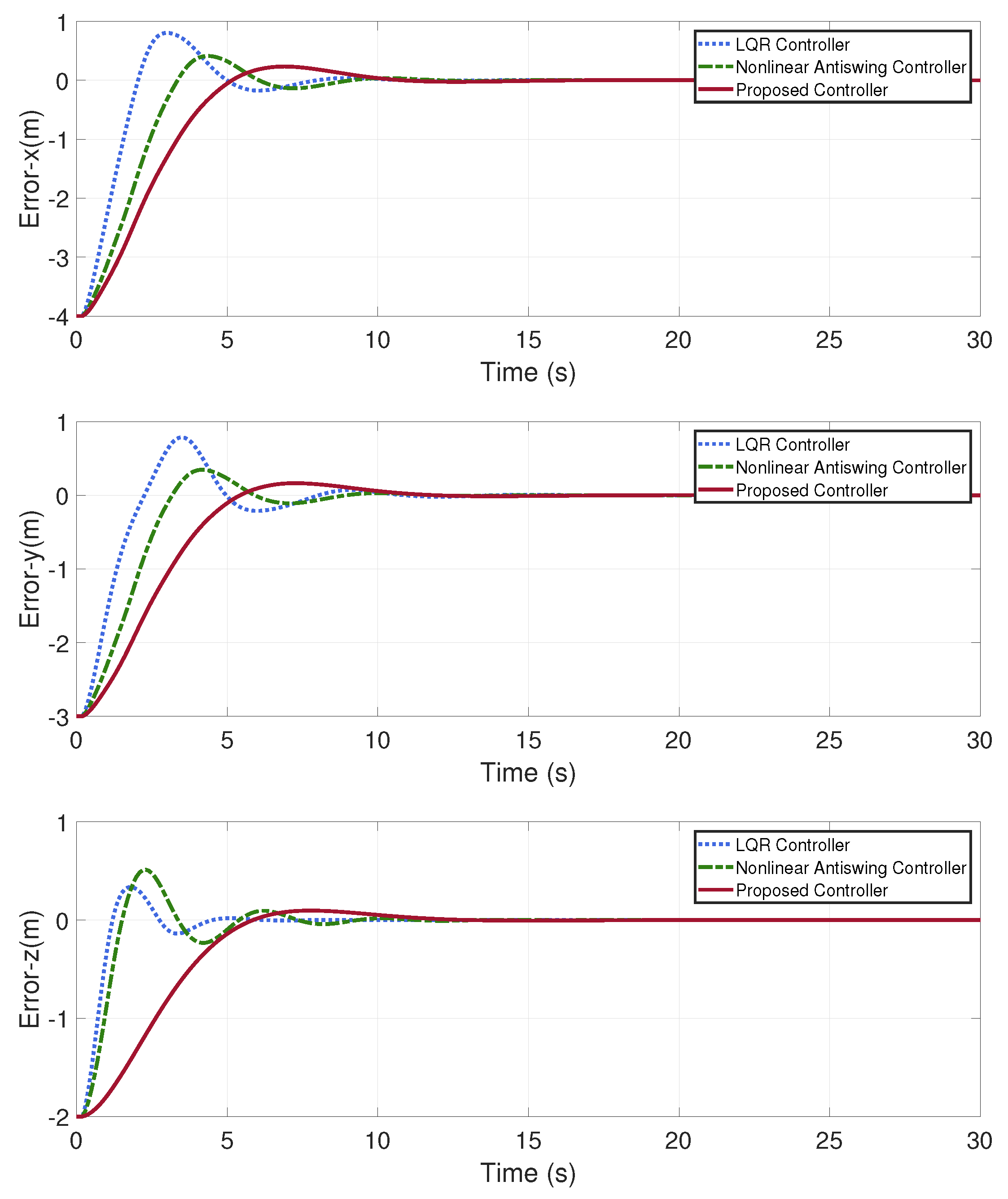
In this case, a stable quadrotor UAV transport system is required to be commanded to reach a specific target point. The initial parameters of the system are as shown in
Table 2, with the elastic deformation of the cables taken into consideration. The simulation results are presented in
Figure 3,
Figure 4,
Figure 5,
Figure 6,
Figure 7 and
Figure 8. To more clearly demonstrate the control performance, error curves for the
and the two swing angles
,
are plotted.
In this case, the quadrotor UAV transportation system is initially in a stable state and now needs to be moved to the target point.
Figure 3 and
Figure 4 illustrate the positions control and anti-swing control of the quadrotor UAV transportation system while carrying a payload.
Figure 5 illustrates the dynamic process of the system’s attitude angle control. The change in length of the cable due to elastic deformation is depicted in
Figure 6. And the errors in the system’s displacement and payload swing angle are shown in
Figure 7 and
Figure 8, respectively.
Based on the data analysis from
Table 3, the control scheme proposed in this paper demonstrates a more stable and rapid displacement control performance compared to both nonlinear antiswing controller and LQR controller.
According to the data from
Table 4, the control scheme designed in this paper exhibits superior anti-swing performance compared to both the nonlinear antiswing controller and the LQR controller.
In
Figure 6, the attitude angles of the quadrotor UAV are maintained within a reasonable range, demonstrating good stability.
4.2. Case 2: Anti-Swing Control
In this case, the quadrotor UAV transport system with an unstable initial state is required to perform control to suppress the swinging of the payload. The initial parameters of the system are as shown in
Table 5, with the elastic deformation of the cables taken into consideration. The simulation results are presented in
Figure 9,
Figure 10,
Figure 11,
Figure 12,
Figure 13 and
Figure 14,
Table 6 and
Table 7. To more clearly demonstrate the control performance, error curves for the
axes and the two swing angles
,
are plotted.
In this case, the quadrotor UAV transportation system is initially unstable. The current task requires the quadrotor UAV to stabilize the payload angles of the swing.
Figure 9 and
Figure 10 illustrate the positions control and anti-swing control of the quadrotor UAV transportation system while carrying a payload.
Figure 11 illustrates the dynamic process of the system’s attitude angle control. The change in length of the cable due to elastic deformation is depicted in
Figure 12. And the errors in the system’s displacement and payload swing angle are shown in
Figure 13 and
Figure 14, respectively.
4.3. Case 3
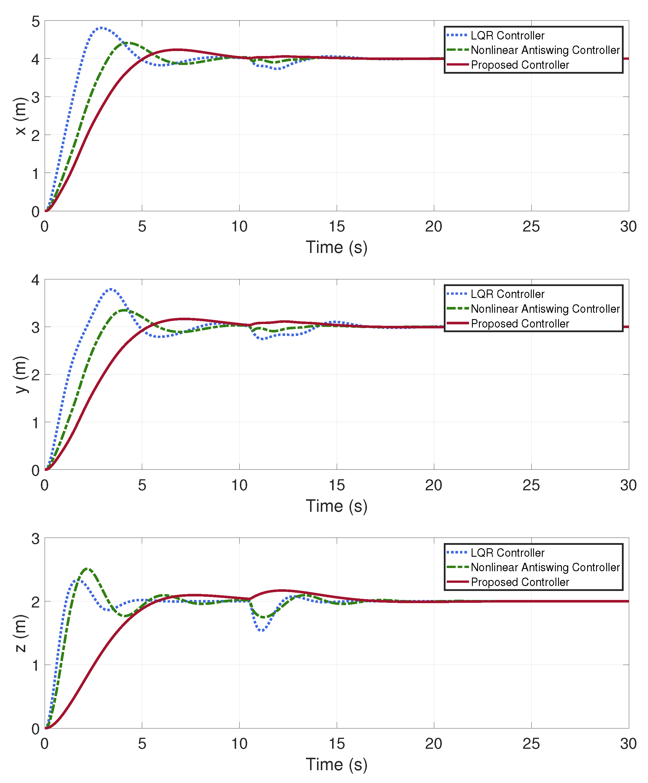
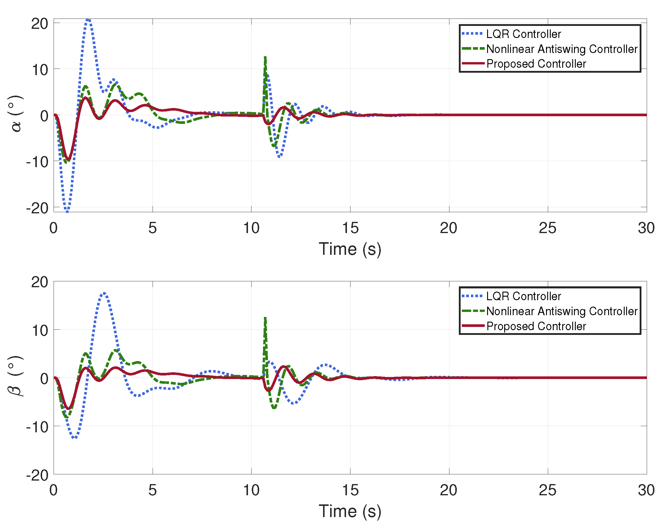
In this case, once the quadrotor UAV transport system has achieved a state of stability, a disturbance is intentionally injected at the 10.5 s mark to evaluate the robustness of the controller.
The simulation results are presented in
Figure 15 and
Figure 16. From the simulation results, it can be seen that when the system reaches a steady state, the system as a whole suddenly encounters the same disturbance, and the feedback and suppression of the perturbation are different for different controllers. The outcomes clearly show that the control scheme proposed in this paper exhibits greater robustness compared to both the LQR controller and the nonlinear antiswing controller.
5. Conclusions
This paper derives the dynamical model of the quadrotor UAV transportation system using Newton-Euler equations and proposes a control strategy based on the energy method and an barrier Lyapunov function. Building on position control and anti-swing control, combined with the force analysis in Newton-Euler equations, this paper introduces an adaptive control design for the unknown cable length connecting the UAV and the payload. The asymptotic stability of the control system is verified using Lyapunov’s theory and the LaSalle’s invariance principle. Ultimately, compared to traditional controllers, the control scheme proposed in this paper exhibits superior performance in terms of displacement control and anti-swing control.
This paper employs the Newton-Euler modeling method, which clearly reveals the interactions between forces. We conducted independent force analyses on the UAV, cable, and payload, providing convenience for future research, especially in dealing with special cases of specific system components and stable control studies under external disturbances. Additionally, due to elastic deformation, the length of the cable may change, and updating the cable’s length in real-time can effectively reduce positioning errors of the payload, ensuring the accuracy and stability of system control. By applying barrier Lyapunov functions, Lyapunov stability theorems, and LaSalle’s invariance theorem, we ensured that the designed controller exhibits good precision and stability during the dynamic regulation of system displacement, attitude angle, and payload swing angle.
