Abstract
With the rapid development of the Internet of Things, the Internet of Vehicles (IoV) has quickly drawn considerable attention from the public. The cooperative unmanned aerial vehicles (UAVs)-assisted vehicular networks, as a part of IoV, has become an emerging research spot. Due to the significant limitations of the application and service of a single UAV-assisted vehicular networks, efforts have been put into studying the use of multiple UAVs to assist effective vehicular networks. However, simply increasing the number of UAVs can lead to difficulties in information exchange and collisions caused by external interference, thereby affecting the security of the entire cooperation and networking. To address the above problems, multiple UAV cooperative formation is increasingly receiving attention. UAV cooperative formation can not only save energy loss but also achieve synchronous cooperative motion through information communication between UAVs, prevent collisions and other problems between UAVs, and improve task execution efficiency. A multi-UAVs cooperation method based on arithmetic optimization is proposed in this work. Firstly, a complete mechanical model of unmanned maneuvering was obtained by combining acceleration limitations. Secondly, based on the arithmetic sine and cosine optimization algorithm, the mathematical optimizer was used to accelerate the function transfer. Sine and cosine strategies were introduced to achieve a global search and enhance local optimization capabilities. Finally, in obtaining the precise position and direction of multi-UAVs to assist networking, the cooperation method was formed by designing the reference controller through the consistency algorithm. Experimental studies were carried out for the multi-UAVs’ cooperation with the particle model, combined with the quadratic programming problem-solving technique. The results show that the proposed quadrotor dynamic model provides basic data for cooperation position adjusting, and our simplification in the model can reduce the amount of calculations for the feedback and the parameter changes during the cooperation. Moreover, combined with a reference controller, the UAVs achieve the predetermined cooperation by offering improved navigation speed, task execution efficiency, and cooperation accuracy. Our proposed multi-UAVs cooperation method can improve the quality of service significantly on the UAV-assisted vehicular networks.
1. Introduction
With the popularization and application of the fifth-generation wireless communications (5G), the Internet of Things (IoT) has become one of the key development technologies in the field of communication. Its vast connectivity and flexible operability have laid a solid foundation for intelligent transportation systems [1]. As an important component of the IoT, the Internet of Vehicles (IoV) has gradually played a driver assistant role for intelligent vehicular networks. Many current intelligent vehicular applications, such as autonomous driving, path planning, traffic control, etc., have high requirements for real-time information of vehicles [2,3]. Vehicles need to transmit information collected by onboard sensors, such as vehicle speed, distance from nearby objects, and the surrounding environment, to the network through roadside units for processing to achieve overall planning of the vehicular networks [4,5]. Although significant progress has been made in the research and application of vehicular networks, there are still many challenges to be faced. In practical situations, vehicles have the characteristic of high-speed movement, and the surrounding traffic environment is particularly complex. Therefore, the connection of vehicular networks is easily affected by environmental factors. Some applications that require high real-time performance, such as high-precision 3D map navigation, rely heavily on reliable network connections [6]. However, the large size of vehicles and traffic environments often make the network face fragile wireless network connections, leading to deteriorating vehicular networks connectivity [7]. Real-time vehicular networks services require high computing power and low latency communication, which require the support of many roadside units. However, when encountering unexpected weather environments, traffic overload caused by public activities, or temporary severe traffic congestion, a fixed network architecture and edge servers are used, which are distributed rigidly and located fixedly; cannot meet the dynamic access needs of vehicles; and have high costs, insufficient practicality, and insufficient security [8,9].
The emergence of unmanned aerial vehicles (UAVs) has influenced the development of many related fields [10]. Due to their good mobility, transmission, and computing capabilities, UAVs [11,12] can help vehicular networks achieve information interactions under special circumstances and provide some cutting edge computing services for ground vehicles [13,14]. The fact is that traffic problems do not always occur in a particular location but change with the flow of people. For example, when a vehicle is involved in a vehicle accident, traffic congestion may occur. Most vehicles gather in one location, which can cause congestion in the vehicular networks and cause trouble for applications with high real-time application. Due to various traffic accidents, traditional fixed-edge servers are difficult to cover all locations in the city. Therefore, a dynamic network edge server is an effective solution.
However, a single UAV has significant limitations in providing services to the vehicular networks, including a small detection range, slow information transmission, and unstable transmission network. Therefore, multiple UAVs can serve as aerial base stations or routers, jointly providing services to the vehicular networks, greatly improving the quality of UAV-assisted vehicular network services [15]. Many scholars have conducted research on multi-UAV-assisted vehicular networks [16,17,18,19]. However, simply increasing the number of UAVs may lead to difficulties in information exchange and conflicts caused by external interference, thereby affecting the security of the entire cooperative network.
Researchers believe that formation control collaboration among multiple UAV networks during task execution can solve the problems [20]. The use of UAVs for cooperative formation can effectively improve the task execution efficiency of multiple UAVs, save energy loss, and enable synchronous and cooperative motion through information communication between UAVs. At the same time, when all UAVs work together instead of a single UAV, it enhances the adaptability of UAV cooperative formation to the surrounding environment. Therefore, how to effectively collaborate on multiple UAVs formation has become a problem that needs to be solved [21,22].
Another problem in UAV cooperative formation control is that each UAV must accelerate differently in both magnitude and potentially in direction if the movement of the reference frame includes a rotational component. This ultimately leads to high position errors when a UAV with limited dynamic capabilities is used.
Efforts have been carried out in recent years. Ju Shuang et al. [23] proposed a cooperative control method of a multi-UAV network based on the sliding mode, which made the multi-UAV network converge to the desired cooperation state smoothly, but there was an unstable chattering phenomenon. Guo et al. [24] proposed a multi-UAV cooperative communication and computing optimization (MCCCO) scheme to reduce UAV task delays, but it requires high computing power and has limited application scope. Wang et al. [25] proposed a cooperation control mechanism for fixed-wing UAVs based on a state consistency model. The six-element state consistency model was used to correlate each stage of flight, but it was not suitable for flight control in complex environments. Sun Yijun et al. [26] proposed a cooperative obstacle avoidance control algorithm for UAV cooperation based on an improved potential field method, which combined graph theory and artificial potential field theory. However, the cooperation changes during the obstacle avoidance process, which is not conducive to the execution of the task.
The above methods can achieve UAV cooperation position adjusting, but there is still room for further improvement in cooperation control when assisting vehicular networks. Aiming at improving the accuracy and stability of UAV cooperation, the use optimization algorithm increases the safe distance between UAVs and enhances the ability of UAVs to fly according to predetermined positions in UAV cooperation [27]. This paper proposes a multiple UAV consistency cooperation algorithm based on arithmetic optimization. A new quadrotor UAV dynamic model is established, which adds a limit of acceleration to the UAV model in Reference [11]. Combined with the controller [28] and the method for solving quadratic programming problem, it overcomes the problems of a limited cooperative control range and unstable operation of existing UAVs. Therefore, the precision and stability of the cooperation control are improved, and the stability of UAV and vehicular networks is enhanced.
The structure of the UAV cooperation control network used in this paper is shown in Figure 1. The consistency module is implemented locally in each UAV and forms the cooperation control framework. Such a UAV-assisted communication network allows the exchange of information and the information of the controlled state through the reference controller. The reference controller takes the required reference information and provides a correct output, which is then distributed in the UAVs cooperation formation control network. Through the consistency module, the reference state information is sent to the quadrotor controller to control the UAVs’ position. The maximum distance consistency module optimizes the distance information through the AOA optimization algorithm to increase the safe distance between UAVs, achieving faster convergence speed and higher accuracy. UAVs’ cooperation formation control network provides a service to vehicular networks.
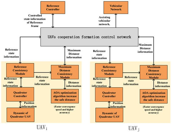
Figure 1.
UAV cooperation control network diagram.
The structure of the UAV cooperation control network used in this paper is shown in Figure 1.
The main contributions of this work are summarized as follows:
- The dynamical analysis of the cooperative control of UAVs is conducted. When UAVs undergo formation changes, if they rotate and fly to change the attitude of the formation, acceleration limitations need to be applied to the UAVs; otherwise, it will cause position errors. Therefore, a new UAV model is established, which adds an acceleration limit to the UAV model in Reference [11]. The purpose of this work is to control the movement of the formation and therefore control the virtual reference frame to maintain the maximum required acceleration within the possible physical limitations of the UAV, thereby improving cooperative formation maintenance.
- We have designed an adaptive arithmetic sine cosine optimization algorithm to solve the balance problem between the global search stage and the local development stage in the arithmetic optimization algorithm. It can achieve a faster convergence speed and higher accuracy.
- The UAV cooperation network was designed with a consensus module based on the consensus algorithm [29], which could achieve more accurate positioning for the UAVs. In addition, the reference controller is designed with a proportional integral differential (PID) [30], and the method for solving the quadratic programming problem is introduced to further improve the accuracy and reliability of the cooperation.
2. Consistency Theory
2.1. Connected Network
An undirected graph G = (N, E) can mathematically model the communication network among N independent UAVs, where N = {1, 2, …, n} is a finite nonempty set of nodes, and E ∈ n × n is an unordered set of nodes, called edges, with each node corresponding to a UAV. An edge (i, j) allows the information flow from node i to j and vice versa. If (i, j) is an edge of G, then nodes i and j are neighbors. Note that edges of the form (i, i) are not allowed. A path consists of a series of nodes, with consecutive nodes being adjacent nodes. If there is a path between each pair of nodes, then the graph G is called a connected graph. In this case, each node pair is connected by a path, and the tree containing all nodes in a graph is called a spanning tree. The diagram is easier to visualize with numbered circles representing nodes and lines representing edges, as shown in Figure 2. Here, the thick solid line represents the possible spanning tree. An equivalent representation of an undirected graph is its adjacency matrix . If (j, i) ∈ E, the elements of matrix A are defined as aij = aji = 1; otherwise, aij = aji = 0.
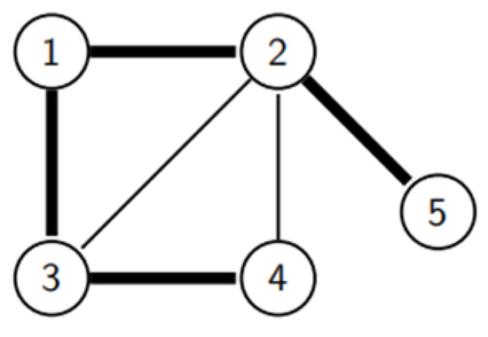
Figure 2.
Five-nodes connected graph and spanning tree.
In Figure 2, the diagonal elements of the corresponding adjacency matrix are zeros, and the matrix is symmetric. The corresponding adjacency matrix A is shown as
Each non-zero element aij indicates that there is an information exchange between the ith and jth UAVs. In a connected graph, information from one UAV can be transmitted to all other UAVs in the network. Another important correlation matrix L is the graph Laplacian, which is given as
where D = [dij]∈Rn×n, and the element dij of matrix D is given as
We comment that the diagonal entry is a node i neighbor number.
The model can be extended by additional nodes, including a virtual leader (VL), which contains the reference information distributed to other nodes. As shown in Figure 3, the number of UAVs from 1 to 5 are named in a series of UAVs. The VL is added to Figure 1 to extend the adjacency matrix, and the added adjacency matrix AVL can be expressed as
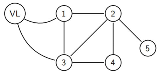
Figure 3.
Connection diagram of five UAVs and one VL.
2.2. Consistency Theory
Information sharing is an important premise for cooperative control, which can be done by a consistency algorithm. Consensus is the result of asymptotically converging to the quantity of interest through local communication. The concept of the consensus algorithm is introduced by
where ωi(t) is the simple integrator information state with the control input at time t. Such a network is composed of n data, with each datum to realize distributed linear agreement. A simple information integrator state expression is given as
Therefore, the whole network can be rewritten as
where σ(t) = [σ1(t), …, σn(t)]T; here, L is the graph Laplacian.
Each data access to local information is available and owns information back to the neighboring average. When σ1(t) = … = σn(t), the convergence and bounded information state can be guaranteed for a connected network graph.
3. Modeling and Control of Quadrotor UAVs
A new quadrotor UAV dynamic model is established, which added a limit of acceleration to the UAV model based on Reference [11]. During the formation of the UAV changes, if the UAVs undergo rotational flight to change the attitude of the formation—that is, the movement of the reference frame includes a rotational component—then the UAVs at different positions in the reference frame will generate different accelerations. If the acceleration limitation of the UAVs is not considered when establishing the dynamic model, it will ultimately lead to significant positional errors of the UAVs.
In Figure 4, six UAVs form a collaborative. When the UAVs change formation posture—that is, the UAVs rotate and fly counterclockwise around the center of the rotating reference frame O by an angle of ω—at this time, each UAV needs to rotate counterclockwise and produce different rotational accelerations ai. The direction of the dashed arrow is the direction of the rotational acceleration, and the longer the arrow, the greater the required acceleration. The further away from the reference frame rotation center, the greater the absolute acceleration required by the UAV, falling behind its expected position. Therefore, the cooperative formation of UAVs will not be able to transform according to the preset formation and cannot complete the task of multi-UAV cooperative vehicular networks. Adding acceleration limitations to the UAV dynamic model is to control the cooperative formation motion of UAVs. This, in turn, controls the virtual reference frame and maintains the maximum required acceleration within the physical limitations of the UAVs, thereby improving the maintenance of the cooperative formation of UAVs.
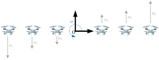
Figure 4.
Different accelerations in a rotating reference frame.
3.1. UAV Modeling
The quadrotor UAV is an underactuated system, and its angular velocity ωi (i = {1, 2, 3, 4}) causes each propeller to generate a force and a moment in the same upward direction. Force fi and upward direction τMi are shown, respectively, as
and
where k+ is the positive lift constant, k− is the positive aerodynamic drag constant, and Ir is the moment of inertia around the rotor axis. The impact of is considered minimal, as in stationary flight ωi ≈ 0; thus, it can be ignored.
Assume that the ground coordinate system is E[X, Y, Z]T and the body coordinate system is B[x, y, z]T. When a UAV does not engage in attitude, the two coordinate systems coincide.
In Figure 5, when the quadrotor UAV pitch roll angle φ, angle θ, and yaw angle ψ change, the transformation matrix R(φ, θ, ψ) of the UAV is
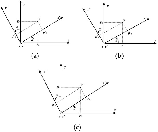
Figure 5.
Attitude angle parameters. (a) Roll angle. (b) Pitch angle. (c) Yaw angle.
3.2. UAV Line Motion Model
Let the orthogonal basis of the ground system be and the orthogonal basis of the machine system be , then the relationship between the two orthogonal bases and the transformation matrix can be expressed as
After analysis of the quadrotor motion model, the vertical upward force of the rotor motion model can be expressed as
where wi(i = 1, 2, 3, 4) is the speed of each motor, and Kt is the lift coefficient provided by each motor. Ti(i = 1, 2, 3, 4) is the upward force of each motor. The transformation torque R between coordinate systems is expressed as
Combing Formulas (12) and (13), a set of four vertical upward forces of the rotor motion model can be expressed as
Considering the self-gravity and environmental resistance of the quadrotor UAV, they are expressed, respectively, as
and
where fx, fy, and fz are the environmental resistance in the x, y, and z directions, respectively. m is the mass of the UAV. According to Newton’s law F = ma, one obtains the following
Formula (17) can be represented, respectively, in two forms as
and
A further derivation of Formula (16) can yield the following result as
where , , and denote ,, and , respectively.
According to the above derivation, the following relationship can be obtained as
The control input U1 corresponds to the total thrust generated by the quadrotors. The linear motion formula of the center of mass of the quadrotor motion model can be obtained by solving the above formulas as
3.3. UAV Angular Motion Model
The UAV can be regarded as a rigid body. The total moment is denoted by M, and the angular momentum is denoted by H. From the theorem of the moment of the center of mass of the rigid body, is expressed as
In the motion model coordinate system, Formula (23) can be rewritten, by combining motor rotation and propeller gyro torque, as
where is the angular velocity vector of the UAV. When the motion model flies in space, the external moment can be decomposed into three parts: M1 is the pitch moment, M2 is the roll moment, and M3 is the yaw moment, which can be obtained by
and
where Kd is the torque of the air resistance, wi is screw rotation rate, and l is wheel base of the quadrotor. Therefore, can be expressed as
For Formula (24), the moment of momentum H can be decomposed as
where , I is the moment of inertia, JTP is the moment of inertia, and Ω is the sum of the angular velocity vector.
The quadrotor is a strictly symmetrical structure; therefore, its component matrix I is represented as
We noted that w can also be expressed as
Substituting Formulas (29) and (30) into (28), is found as
According to Formulas (30) and (31), Formula (24) can be rewritten as
Finally, substituting Formulas (27) and (32) into Formula (24), can be derived as
By combining the one-to-one relationship of each determinant with Formula (34), it can be derived as
The angular motion model of the quadrotor UAV can be derived as
where, U2, U3, and U3 are the control inputs for the roll angle, pitch angle, and yaw angle, respectively.
In order to facilitate the control, on the premise of ignoring the external disturbance, a simplified dynamic model of the quadrotor UAV is established. After the simplification of Formulas (22) and (35) with drag coefficient Ki, disturbance di, and the Lagrange formula, the dynamic model of the quadrotor UAV can be obtained, respectively, as
and
where l represents the arm length, Ii (i = 1, 2, 3) represents the moment of inertia, and the system selects the tracking trajectory [x, y, z] and roll angle φd, simultaneously stabilizing the other two angles.
3.4. Limit of Acceleration
The control input U1 corresponds to the total thrust generated by the quadrotors. Therefore, U1 is constrained by the upper and lower limits when the rotor orientation is fixed, which, in turn, limits the maximum acceleration and velocity. Due to simulating the air friction drag, the maximum acceleration and the minimum acceleration in the ZW direction can be expressed, respectively, as
and
The same results can be obtained for the horizontal x–y plane. Here, the maximum pitch θ and roll angles φ limit the acceleration performance. Assuming a constant height, these angle ranges are −|θmax| ≤ θ ≤ θmax and −|φmax| ≤ φ ≤ φmax, respectively. Therefore, the maximum acceleration in the ZX direction and the maximum acceleration in the ZY direction can be expressed, respectively, as
and
For the maximum acceleration in the positive and negative coordinate directions, matrix apos represents the maximum acceleration in the positive coordinate direction, and matrix aneg represents the maximum acceleration in the negative coordinate direction. These two matrices apos and aneg can be expressed, respectively, as
and
4. Adaptive Arithmetic Sine Cosine Optimization Algorithms
The basic arithmetic optimization algorithm (AOA) is divided into three steps: in the initial stage, using the mathematical optimizer accelerate (MOA) function to select the search stage. Then, it enters the global search stage and uses the multiplication–division method to find the optimal solution. Finally, the AOA enters the local development stage and calculates the development result by the addition and subtraction method. However, the optimization performance of the AOA and the balance between the global search phase and the local development phase still leave great room for improvement. In order to further improve the accuracy of UAVs’ cooperation control and improve the optimization ability of the algorithm, an adaptive arithmetic sine cosine optimization algorithm is proposed in this paper, which enables individuals to find the equilibrium position of the best global search stage and the local development stage. The sine cosine algorithm is simple in principle and easy to implement. It can increase the diversity of the population and improve the optimization accuracy significantly after merging with the arithmetic optimization algorithm. It includes an adaptive optimization stage, global search stage, and local development stage.
4.1. Adaptive Optimization Stage
The population vector X at this stage consists of an N × n dimensional matrix, and its model is given as
Before adaptive optimization, one selects a random number r1(0 < r1 < 1) and compares it with the MOA, If r1 < MOA, start the global search phase; otherwise, one performs the local development phase. The mathematical model of the adaptive coefficient MOA is shown as
where t is the current number of iterations, Tmax is the maximum number of iterations, and Mmin and Mmax are the minimum and maximum values of the MOA function, taking values of 0.2 and 1, respectively. The optimized adaptive coefficient MOA can effectively solve the problems of the insufficient global search stage and limited local development stage of the AOA, thus accelerating the convergence speed.
4.2. Global Search Stage
In this stage, the multiplication-division search strategy is used to find a better solution. Taking the random number r2(0 < r2 < 1), if r2 > 0.5, one could perform the multiplication search strategy; otherwise, the division search strategy is executed. The mathematical model of the AOA in the global search stage can be formulated as follows:
and
where is ith and jth position of the t + 1 iteration, is the jth position of the optimal individual, ε is a small integer, and are the upper and lower bounds of the jth position, respectively, μ is the control parameter (typically μ = 0.5), MOP(t) is the mathematical optimization rate coefficient, and α represents the sensitivity parameter (typically α = 5).
4.3. Local Development Phase
In the local development stage, if only the addition and subtraction search strategy is used for development and calculation, it will lead to insufficient local development ability and poor result accuracy. Therefore, an improved sine cosine algorithm (ISCA) is designed to maintain the population diversity in the later stage of the algorithm iteration and strengthen the development capacity. The ISCA is formulated as
where , with a being a constant (typically a = 2); is the ith and jth positions of the t iteration; and r2, r3, and r4 are random range factors, with r2 ϵ [0, 2π], r3 ϵ [0, 2], and r4 ϵ [0, 1]. We note that r1 can complete the transformation from a global search to local development, r2 determines how far to move, r3 decides the impact generated, and r4 determines whether the update method for individuals in the population is a sine algorithm or a cosine algorithm. In the local development stage after fusion, oscillation is used to maintain the diversity of the population, which could greatly enhance the performance of the local networking development.
5. Quadrotor Cooperation Control Design
5.1. Cooperation Control Framework
The quadrotor UAV can position itself in space, and when UAVs collaborate, they also need to know the desired position, which depends on the current reference system. rdrel,i represents the relative expected position of each UAV. Let ξrcontr be the state of the coordinate system fR: {OR; XR; YR; ZR}. In Figure 6, three quadrotor UAVs form a triangular formation, and the circle point is the desired position rdi set in the coordinate system fR. The diamond is the actual position ri. Each UAV has its own state ξi.
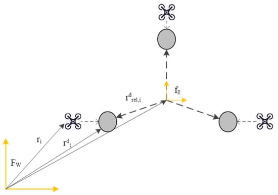
Figure 6.
Agreed results of the reference system.
After reaching a consensus on the reference system of all UAVs, the UAVs’ state ξi can be shown as
In contrast to Figure 6, the result with no consensus of all UAVs is shown in Figure 7. For this case, the ideal position of a UAV deviates from the triangle structure, because the information state of ξi does not converge.
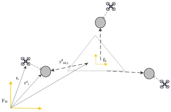
Figure 7.
The result of no agreement on the reference system.
The consistency module is implemented locally in each UAV and forms the cooperation control framework, as shown in Figure 8. Such a UAV-assisted communication network allows the exchange of information, and the information of the position controller and the direction controller can be obtained through the reference controller. The reference controller takes the required reference locus ξr and provides a correct output ξrcontr, which is then distributed in the UAV-assisted communication network through the consistency module. The revised output considers the dynamic limitations of the UAV involved and ultimately reduces the position error. The maximum acceleration occurs in the farthest UAV during cooperation, so the cooperation feedback is in the form of the quadrotor information state ζi, carrying the maximum distance data. It is provided by the maximum distance consistency module, which is implemented locally in each quadrotor.
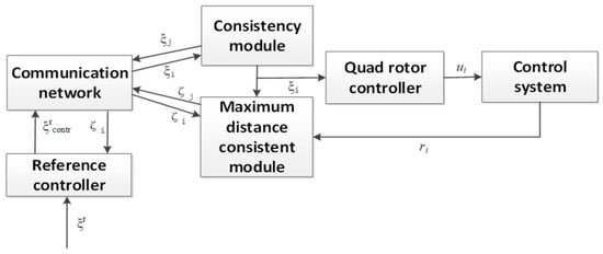
Figure 8.
Overview of the cooperation control framework.
5.2. Consistency Module
The reference system state ξrcontr can be described by the central position of the inertial system FW and the three Euler angles (Figure 9). ξrcontr can be written as
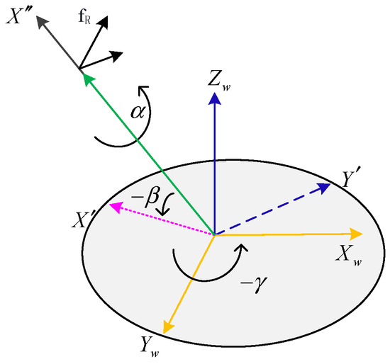
Figure 9.
Direction of the reference system and Euler angle.
With ξi being the control input, ξi and i can be expressed, respectively, as
and
where aij is the (i, j) term of the extended adjacency matrix AVL, ai(n+1) is the (i, n + 1) term of the extended adjacency matrix AVL, κ is a positive scalar, and ηi is the ith row of the extended adjacency matrix AVL, which ensures the cooperation control process does not limit the number of each UAV. The first term in Formula (53) is related to the information state of the UAV, and the second term is related to the ξrcontr. Adding a derivative term to ξi enables the algorithm to follow any variable reference value. The desired absolute position rdi is calculated with each UAV’s own state ξi and the known desired position rdrel,i relative to the virtual coordinate system, and it can be expressed as
where matrix is a rotation matrix based on the Euler angels αi, βi, and γi from the reference system to the world coordinates. The desired absolute position is eventually passed to the local controller to locate the UAVs for networking.
5.3. Maximum Distance Consistent Module
Similar to the design of the consistency module, the purpose of designing the maximum distance consistency module is to ensure that the UAVs can adapt to distance changes at different positions during collaboration, thereby ensuring the flexibility of the UAV-assisted vehicular networks. The maximum size of the UAVs’ cooperation frame refers to the desired position of the farthest point in each coordinate direction from the origin of the virtual reference system, which can be expressed as
where ζr is the globally correct value. Note that each UAV has its own location. After the UAVs exchange information, ζi can be written as
During UAV-assisted vehicular networking, each UAV has a maximum positive distance dmaxi and a maximum negative distance dmini, as shown in Figure 10.
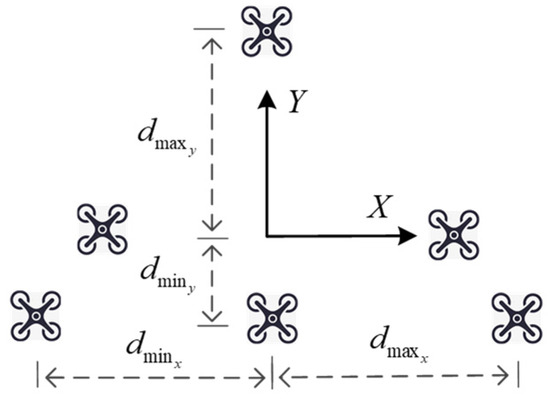
Figure 10.
Maximum positive and negative distances to the virtual center.
After synchronization is maximized for cooperation, the information state ζj of each UAV can be expressed as
where j ∈ Ni, and Ni is the set size of the ith node. Each UAV sends its own information status ζj, and all connected nodes will update their information status only if the information status is greater than or less than this value. Before information is exchanged, the information state is initialized to [rdrel,I rdrel,i]T. The consistency algorithm has a distributed feature when exchanging local information. The virtual leader can connect to any follower and obtain its information status. When the spanning tree exists, the consistency algorithm can guarantee that ζi(t) → ζr.
5.4. Reference Controller
The reference controller has the current and expected states of the reference system, denoted as ξrcontr and ξr, respectively. In addition, if the reference controller is effectively connected to the ith UAV, it could receive estimated data values dmax and dmin for the maximum and minimum distances, respectively, from the virtual center to the communication network. The dmax and dmin are given, respectively, as
and
where d1 to d6 denote the first to the sixth elements of the distance feedback, respectively.
In the above case, the information is available to the reference controller. Therefore, a controlled reference system state ξrcontr is generated, and the virtual reference system state ξr is closely connected to the required information state. At the same time, the dynamic constraints of the UAV are considered through the cooperation information state ζi feedback. The maximum acceleration amax, the minimum acceleration amin, and the angular velocity vector ω for the cooperative UAVs in the inertial system can be found, respectively, as
and
where is a rotation matrix, and is a reference system Euler angle matrix.
The angular velocity vector ω is obtained from the time derivatives of the three Euler angles with respect to the inertial system after the rotation matrix transformation. Thus, the angular acceleration vector can be shown as
The acceleration constraints are expressed, respectively, in the following inequalities as
and
If either of the two maximum accelerations exceeds the quadrotor physical limits, a positional error will occur. Thus, the task of the reference controller is to restrict the desired state of the reference system ξr in order to satisfy Formulas (64) and (65). The maximum acceleration is nonlinear due to the angular velocity vector ω. Therefore, the correction vector and correction value are added, but these will cause a large error between the controlled reference state ξrcontr and the expected value. A PID controller is added to the reference controller to repair the error and improve the system’s adaptability and robustness. The complete form of the reference controller is given as
where , , and are PID controller coefficients.
The diagram is shown in Figure 11. If Formulas (65) and (66) are satisfied, the correction vector ca equals zero, and an asymptotically stable dynamic PID controller can be obtained. The correction vector ca is given by
which can be simplified as
where .
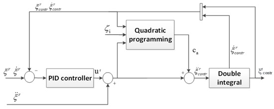
Figure 11.
Reference controller structure.
When the maximum acceleration exceeds the limit, the vector ca can be calculated by solving the quadratic programming problem. Under the constraints in Formulas (64) and (65), the vector norm of ca can be minimized, and the acceptable ξrcontr value is obtained by combining it with the PID controller output ur. By calculating the minimum value of the corrected vector, the maximum acceleration is kept within the physical limit of the UAV. Among them, the quadratic programming problem can be shown as
with
where Ha is the weight matrix, h1–h6 are the weight elements, Ga is the constraint matrix of the optimization problem, and ha is the constraint vector of the optimization problem.
The optimization problems in quadratic programming are formulated as
and
where G1 is the matrix of the maximum acceleration in the optimization problem, h1 is the vector of the maximum acceleration in the optimization problem, I3 is the identity matrix of 3 × 3, is the constraint matrix of the maximum acceleration in the optimization problem, and is the constraint vector of the maximum acceleration in the optimization problem.
Similarly, using the minimum acceleration constraint from Formula (64), the expressions of the optimization problems in quadratic programming are formulated as
and
In summary, the linear formula constraints of the quadratic programming problems can be expressed, respectively, as
and
Since the weight matrix is composed of elements greater than zero, it is positive definite, and the optimization problem is convex, which can be solved by solving the convex quadratic programming problem.
6. Simulation Analysis
Starting with the modeling and control of a single quadrotor UAV, the UAV dynamic model is shown in Formula (39), which can be extended to multiple UAVs’ cooperation to assist the vehicular communication network. The complete UAVs cooperation control structure is simulated with or without a reference controller. The hardware platform is a computer with an Intel Core I7-13700H 2.3GHz CPU and 16G memory. Each UAV dynamic coefficient obtained in the test is calculated and analyzed, and the cooperation effect is verified by MATLAB R2021a and Simulink software platforms, which proves the effectiveness of the proposed method. The experiment assumes that communication between UAVs is always successful, without considering the UAV communication model. The UAV model is simulated using Simulink, as shown in Figure 12.
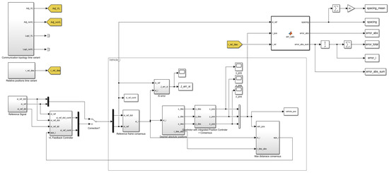
Figure 12.
UAV Simulink model.
In the simulation experiment, six UAVs were used for formation cooperation control, and custom simulation was used in the experiment. In the MATLAB simulation experiment, we assume that communication between UAVs is not disturbed; the weather is stable; and there is no meteorological interference such as wind, rain, and snow. The UAV has sufficient battery and will not malfunction. The UAV rotors perfectly accurately fulfill the command of the optimization algorithm. A virtual cooperation scene is shown in Figure 13.
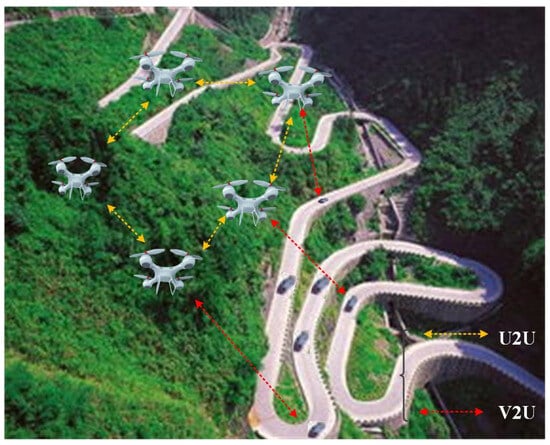
Figure 13.
A virtual cooperation scenario.
The UAV dynamic coefficient obtained by our experiment is shown in Table 1. One can select the appropriate position controller, as shown in Figure 14, and set the controller gain to ensure a stable step response. A high controller gain ensures a fast dynamic response to adjust the height of UAVs’ cooperation, as shown in Figure 15.

Table 1.
UAV power coefficient.
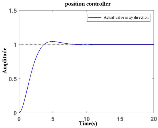
Figure 14.
Response of the position controller in the x and y directions.
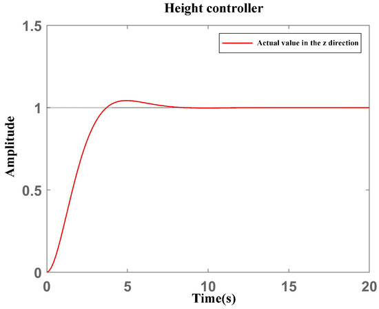
Figure 15.
Response of the height controller in the z–axis direction.
The average acceleration of the simulated UAVs’ cooperation in the x–y–z direction is shown in Figure 16. Our analysis shows that the proposed UAV model can meet the cooperation requirements. The positioning speed is fast, the operation is stable, and it can provide basic data for cooperation position adjusting.
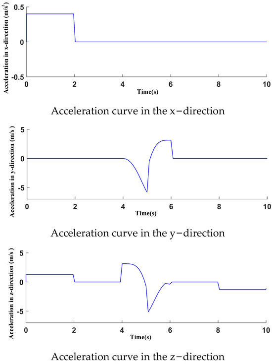
Figure 16.
Acceleration curves in the x−y−z direction.
Without a reference controller, the cooperation control was carried out according to the predetermined trajectory, and the UAV position was plotted at four moments in 12 s of simulation time without reference correction ca. The three–dimensional and two–dimensional modes are shown in Figure 17 and Figure 18, respectively. The UAVs’ cooperation changed significantly at 8 s, because the UAVs’ cooperation position adjusting was wrong due to the turning and extra time needed to readjust the cooperation positions. At 12 s, they reached the end of the predetermined track, but the cooperation position was not adjusted to the initial state, and a certain amount of cooperation time was sacrificed. Therefore, additional adjustment is required.
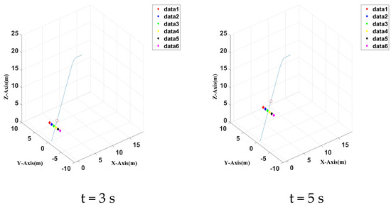
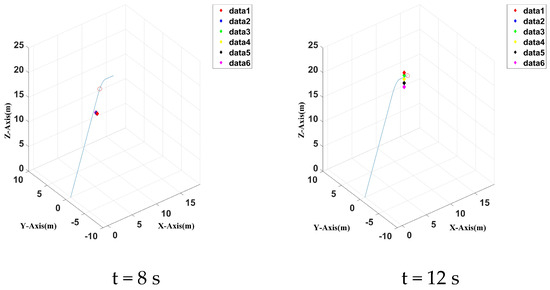
Figure 17.
Three–dimensional positions of six UAVs at four different time spots without a reference controller.
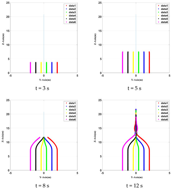
Figure 18.
Two–dimensional positions of six UAVs at four different time spots without a reference controller.
When there is a reference controller, the UAVs’ cooperation control is carried out according to a predetermined trajectory. Given a reference correction ca, the position of a UAV at four moments is plotted within the simulation time of 10 s, as shown in Figure 19 and Figure 20 for three–dimensional and two–dimensional modes, respectively. Clearly, when there is a reference controller, the cooperation control is faster and more accurate, and the cooperation frame shape does not change. At 8 s, the UAVs’ cooperation positions can be maintained in their initial state, and no more cooperation adjustment time is required, so the task can be completed faster with improved accuracy.
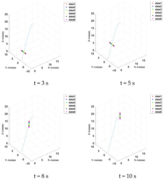
Figure 19.
Three–dimensional positions of six UAV at four different time spots with a reference controller.
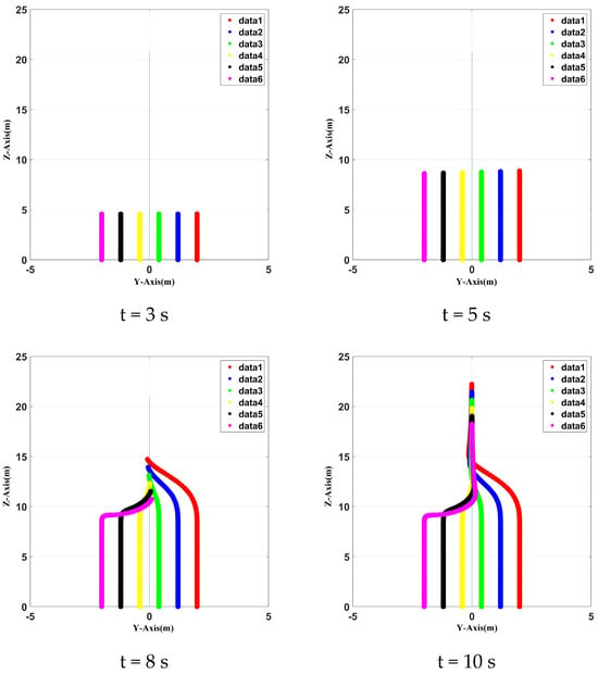
Figure 20.
Two–dimensional positions of six UAVs at four different time spots with a reference controller.
In terms of time, the no reference controller will lag significantly behind the reference controller. Meanwhile, the cooperation error is much larger than that with a reference controller, especially at the turning point. After the turn, the error cannot be corrected as quick as if there were a reference controller; therefore, it will cause the error to accumulate and destroy the original cooperation position. The errors with or without a reference controller are clearly shown in Figure 21 and Figure 22, as we have analyzed.
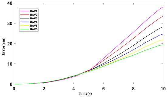
Figure 21.
Formation errors for the non–reference controller.
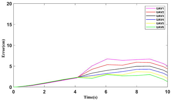
Figure 22.
Cooperation errors for the reference controller.
When multiple UAVs fly at the starting point, the spacing of each two UAVs is initially 0.8 m. In this work, the proposed algorithm can reach the end point after 10 s with a reference controller, so the cooperation time of 10 s is used as a reference. At 5 s, when the turn is about to start, each UAV may produce a certain degree of error. The comparison of the average distance between adjacent UAVs is shown in Figure 23. The algorithm in this paper can keep the spacing within the minimum range of 0.2 m to prevent collision between UAVs’ cooperation position to the maximum extent. Under the action of the reference controller, it can produce errors slightly later than other cases and control the spacing distance within the safe range. We note that the maximum interval distance of Reference [31] was less than 0.1 m. Therefore, it was easy to cause a collision of UAVs, resulting in networking safety accidents. The algorithm in Reference [32] was slightly better than the proposed algorithm in terms of time, but the maximum interval distance was less than 0.1 m, with insufficient security. In such cases, the UAV cooperation position fluctuates greatly, which is more susceptible to external interference.
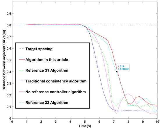
Figure 23.
Comparison of distances between adjacent UAVs.
Traditional consistency algorithms [26] only use consistency theory and do not use the AOA algorithm for optimization. Table 2 shows a comparison between the whole time, cooperative formation recovery time, and maximum interval distance of different cooperation algorithms. The proposed algorithm in this work offers advantages in the whole time, cooperative formation recovery time, and maximum interval distance. It also improves the UAVs’ cooperation speed on the premise of maintaining safety.

Table 2.
Comparison of different algorithms.
7. Conclusions
This paper designed a consensus cooperation method for multi-UAVs based on arithmetic optimization to solve the cooperation problem in multi-UAV-assisted vehicular networks. It established a four-rotors dynamic model, combined arithmetic optimization algorithms, and added a reference controller to form a precise position cooperation networking method. It enhanced stability compared to the traditional cooperation method and designed a cooperation feedback strategy, which can effectively adjust the cooperation of UAVs. We added a maximum interval distance consistency module that can significantly improve the accuracy of collaborative position preservation. This networking method can maintain accurate collaboration positions, minimize collaboration errors, and greatly reduce the collaboration time of the network under the action of the reference controller. The experimental results showed that the algorithm proposed in this paper takes the shortest whole time. The cooperative formation recovery time is improved by at least 1 s compared to other algorithms. The maximum interval distance can reach 0.65 m, which is notably smaller than other algorithms. In the future, we will investigate other UAV network impact factors, such as channel randomness, uncertainty models, uncertain channel disturbances, and multi-relay cooperative/communication models.
Author Contributions
Conceptualization, M.N. and H.H.; data curation, D.L., M.S.M. and H.W.; methodology, H.H., M.N. and D.L.; software, H.H.; validation, H.H., D.L. and M.N.; formal analysis, M.N.; investigation, M.N., D.L. and T.G.; resources, M.S.M., F.X. and H.W.; writing—original draft preparation, H.H., D.L. and M.N.; writing—review and editing, M.N.; visualization, H.H., M.N. and M.S.M.; supervision, M.N.; project administration, M.N., T.G. and M.S.M.; funding acquisition, H.H. and M.N. All authors have read and agreed to the published version of the manuscript.
Funding
This research was supported by the National Natural Science Foundation of China, grant numbers 52172379 and 52172324, the Project of the Ministry of Science and Technology of China, grant number G2021171024L, the Innovation Creative Centre Project of Shaanxi Province, grant number 300201000173, the Fundamental Research Funds for the Central Universities, CHD under Grant 300102384901, and the special fund for the basic scientific research business expenses of Chang’an University Central Universities, grant number 300102324501.
Data Availability Statement
The data presented in this study are available on request from the corresponding author.
Conflicts of Interest
The authors declare no conflicts of interest.
References
- Yu, M. Construction of regional intelligent transportation system in smart city road network via 5G network. IEEE Trans. Intell. Transp. Syst. 2022, 24, 2208–2216. [Google Scholar] [CrossRef]
- Bréhon–Grataloup, L.; Kacimi, R.; Beylot, A.L. Mobile edge computing for V2X architectures and applications: A survey. Comput. Netw. 2022, 206, 108797. [Google Scholar] [CrossRef]
- Hildebrand, B.; Baza, M.; Salman, T.; Tabassum, S.; Konatham, B.; Amsaad, F.; Razaque, A. A comprehensive review on blockchains for Internet of Vehicles: Challenges and directions. Comput. Sci. Rev. 2023, 48, 100547. [Google Scholar] [CrossRef]
- Mishra, D.; Trotta, A.; Traversi, E.; Felice, M.; Natalizio, E. Cooperative Cellular UAV-to-Everything (C-U2X) communication based on 5G sidelink for UAV swarms. Comput. Commun. 2022, 192, 173–184. [Google Scholar] [CrossRef]
- Kilanioti, I.; Rizzo, G.; Masini, B.M. Intelligent transportation systems in the context of 5G-beyond and 6G networks. In Proceedings of the 2022 IEEE Conference on Standards for Communications and Networking (CSCN), Thessaloniki, Greece, 28–30 November 2022; pp. 82–88. [Google Scholar]
- Wang, D.; Wu, M.; Chakraborty, C.; Min, L.; He, Y.; Guduri, M. Covert communications in air-ground integrated urban sensing networks enhanced by federated learning. IEEE Sens. J. 2023, 24, 5636–5643. [Google Scholar] [CrossRef]
- Qi, W.; Song, Q.; Guo, L.; Jamalipour, A. Energy-efficient resource allocation for UAV-assisted vehicular networks with spectrum sharing. IEEE Trans. Veh. Technol. 2022, 71, 7691–7702. [Google Scholar] [CrossRef]
- Wang, D.; Wu, M.; Wei, Z.; Yu, K.; Min, L.; Mumtaz, S. Uplink secrecy performance of RIS-based RF/FSO three-dimension heterogeneous networks. IEEE Trans. Wirel. Commun. 2023, 23, 1798–1809. [Google Scholar] [CrossRef]
- Wang, D.; He, T.; Lou, Y.; Pang, L.; He, Y.; Chen, H.H. Double-edge computation offloading for secure integrated space-air-aqua networks. IEEE Internet Things J. 2023, 10, 15581–15593. [Google Scholar] [CrossRef]
- Hurst, W.; Evmorfos, S.; Petropulu, A.; Mostofi, Y. Unmanned Vehicles in 6G Networks: A Unifying Treatment of Problems, Formulations, and Tools. arXiv 2024, arXiv:2404.14738. [Google Scholar]
- Guo, X.; Niu, P.; Zhao, D.; Li, X.; Wang, S.; Chang, A. Model-free controls of manipulator quadrotor UAV under grasping operation and environmental disturbance. Int. J. Control. Autom. Syst. 2022, 20, 3689–3705. [Google Scholar] [CrossRef]
- Ollervides-Vazquez, E.J.; Tellez-Belkotosky, P.A.; Santibañez, V.; Rojo-Rodriguez, E.G.; Reyes-Osorio, L.A.; Garcia-Salazar, O. Modeling and Simulation of an Octorotor UAV with Manipulator Arm. Drones 2023, 7, 168. [Google Scholar] [CrossRef]
- Yang, C.; Liu, B.; Li, H.; Li, B.; Xie, K.; Xie, S. Learning based channel allocation and task offloading in temporary UAV-assisted vehicular edge computing networks. IEEE Trans. Veh. Technol. 2022, 71, 9884–9895. [Google Scholar] [CrossRef]
- Araf, S.; Saha, A.S.; Kazi, S.H.; Tran, N.H.; Alam, M.G. UAV assisted cooperative caching on network edge using multi-agent actor-critic reinforcement learning. IEEE Trans. Veh. Technol. 2022, 72, 2322–2337. [Google Scholar] [CrossRef]
- Zheng, G.; Xu, C.; Wen, M.; Zhao, X. Service caching based aerial cooperative computing and resource allocation in multi-UAV enabled MEC systems. IEEE Trans. Veh. Technol. 2022, 71, 10934–10947. [Google Scholar] [CrossRef]
- Gai, H.; Zhang, H.; Guo, S.; Yuan, D. Information freshness-oriented trajectory planning and resource allocation for UAV-assisted vehicular networks. China Commun. 2023, 20, 244–262. [Google Scholar] [CrossRef]
- Khan, A.A.; Laghari, A.A.; Shafiq, M.; Awan, S.A.; Gu, Z. Vehicle to everything (V2X) and edge computing: A secure lifecycle for UAV-assisted vehicle network and offloading with blockchain. Drones 2022, 6, 377. [Google Scholar] [CrossRef]
- Liu, Y.; Yang, C.; Chen, X.; Wu, F. Joint Hybrid Caching and Replacement Scheme for UAV-Assisted Vehicular Edge Computing Networks. IEEE Trans. Intell. Veh. 2023, 9, 866–878. [Google Scholar] [CrossRef]
- Huang, H.; Wen, X.; Niu, M.; Miah, M.S.; Gao, T.; Wang, H. Multi-UAVs assisted path planning method for terrain-oriented air-ground collaborative vehicular network architecture. IEEE Trans. Intell. Veh. 2024. early access. [Google Scholar] [CrossRef]
- Chen, M.; Li, B.; Wang, J.; Wang, G. A Formation Control Algorithm for Air-Ground Cooperative UAV. In Proceedings of the 2022 14th International Conference on Wireless Communications and Signal Processing (WCSP), Nanjing, China, 1–3 November 2022; pp. 741–747. [Google Scholar]
- Chen, J.; Li, T.; Zhang, Y.; You, T.; Lu, Y.; Tiwari, P.; Kumar, N. Global-and-local attention-based reinforcement learning for cooperative behaviour control of multiple UAVs. IEEE Trans. Veh. Technol. 2023, 73, 4194–4206. [Google Scholar] [CrossRef]
- Li, T.; Leng, S.; Wang, Z.; Zhang, K.; Zhou, L. Intelligent resource allocation schemes for UAV-swarm-based cooperative sensing. IEEE Internet Things J. 2022, 9, 21570–21582. [Google Scholar] [CrossRef]
- Ju, S.; Wang, J.; Dou, L.; Gu, W. Cooperative Formation Control of Multiple UAV Systems Based on Sliding Mode Control. Navig. Position. Timing 2022, 9, 74–83. [Google Scholar]
- Guo, H.; Wang, Y.; Liu, J.; Liu, C. Multi-UAV cooperative task offloading and resource allocation in 5G advanced and beyond. IEEE Trans. Wirel. Commun. 2023, 23, 347–359. [Google Scholar] [CrossRef]
- Wang, H.; Jin, C.; Xu, B.; Chen, M. State Coherence Model Based Formation Control Mechanism for Fixed-wing Drones. J. Chin. Comput. Syst. 2022, 43, 1505–1510. [Google Scholar]
- Sun, Y.; Dai, J.; Ying, J.; Nie, H. Cooperative Obstacle Avoidance Control Algorithm for UAV Formation Based on Improved Potential Field Method. Comput. Appl. Softw. 2022, 39, 299–304+312. [Google Scholar]
- Wang, Z.; Cheng, W.; Xin, Y.; Yang, Z.; Huang, Z. Formation Control of Quadrotor UAV Based on Terminal Sliding Mode Control. Flight Control. Detect. 2023, 6, 44–51. [Google Scholar]
- Flores, B.F.; Mastroeni, G. First- and Second-Order Optimality Conditions for Quadratically Constrained Quadratic Programming Problems. J. Optim. Theory Appl. 2022, 193, 118–138. [Google Scholar] [CrossRef]
- Huang, Y.; Tang, J.; Lao, S. UAV group formation collision avoidance method based on second-order consensus algorithm and improved artificial potential field. Symmetry 2019, 11, 1162. [Google Scholar] [CrossRef]
- Noordin, A.; Mohd, B.M.A.; Mohamed, Z. Real-Time Implementation of an Adaptive PID Controller for the Quadrotor MAV Embedded Flight Control System. Aerospace 2023, 10, 59. [Google Scholar] [CrossRef]
- Gao, C.; Ma, J.; Li, T.; Shen, Y. Hybrid swarm intelligent algorithm for multi-UAV formation reconfiguration. Complex Intell. Syst. 2023, 9, 1929–1962. [Google Scholar] [CrossRef]
- Chen, Y.; Deng, T. Leader-Follower UAV formation flight control based on feature modelling. Syst. Sci. Control. Eng. 2023, 11, 2268153. [Google Scholar] [CrossRef]
Disclaimer/Publisher’s Note: The statements, opinions and data contained in all publications are solely those of the individual author(s) and contributor(s) and not of MDPI and/or the editor(s). MDPI and/or the editor(s) disclaim responsibility for any injury to people or property resulting from any ideas, methods, instructions or products referred to in the content. |
© 2024 by the authors. Licensee MDPI, Basel, Switzerland. This article is an open access article distributed under the terms and conditions of the Creative Commons Attribution (CC BY) license (https://creativecommons.org/licenses/by/4.0/).