Abstract
In environments where satellite signals are blocked, initializing UAV swarms quickly is a technical challenge, especially indoors or in areas with weak satellite signals, making it difficult to establish the relative position of the swarm. Two common methods for initialization are using the camera for joint SLAM initialization, which increases communication burden due to image feature point analysis, and obtaining a rough positional relationship using prior information through a device such as a magnetic compass, which lacks accuracy. In recent years, visual–inertial odometry (VIO) technology has significantly progressed, providing new solutions. With improved computing power and enhanced VIO accuracy, it is now possible to establish the relative position relationship through the movement of drones. This paper proposes a two-stage robust initialization method for swarms of more than four UAVs, suitable for larger-scale satellite denial scenarios. Firstly, the paper analyzes the Cramér–Rao lower bound (CRLB) problem and the moving configuration problem of the cluster to determine the optimal anchor node for the algorithm. Subsequently, a strategy is used to screen anchor nodes that are close to the lower bound of CRLB, and an optimization problem is constructed to solve the position relationship between anchor nodes through the relative motion and ranging relationship between UAVs. This optimization problem includes quadratic constraints as well as linear constraints and is a quadratically constrained quadratic programming problem (QCQP) with high robustness and high precision. After addressing the anchor node problem, this paper simplifies and improves a fast swarm cooperative positioning algorithm, which is faster than the traditional multidimensional scaling (MDS) algorithm. The results of theoretical simulations and actual UAV tests demonstrate that the proposed algorithm is advanced, superior, and effectively solves the UAV swarm initialization problem under the condition of a satellite signal rejection.
1. Introduction
In recent years, the deployment and application of UAV (Unmanned Aerial Vehicle) swarms have increased significantly due to their versatility and effectiveness in a wide range of applications [1,2]. These applications include search and rescue operations [3], environmental monitoring [4], agricultural monitoring [5,6], and military missions [7]. The collective operation of a swarm of drones provides better coverage, greater robustness, and greater efficiency than drones operating alone. Collaborative positioning involves different tasks, including collaborative mapping and positioning [8]. However, accurately and quickly initializing the relative position of a drone swarm, especially in environments where satellite signals are weak or unavailable, presents a fundamental challenge.
Traditionally, the positioning of UAV swarms has relied on global navigation satellite systems (GNSSs) such as GPS (Global Positioning System) and Beidou. However, in many critical scenarios, satellite signals may be unavailable or unreliable due to interference, urban canyons, dense forests, or indoor environments [9]. Therefore, it became necessary to develop alternative methods for initializing and positioning UAV swarms that do not rely on satellite signals. Various approaches have been explored, including the use of airborne sensors such as cameras [10], lidar [11], inertial measurement units (IMUs) [12], WiFi (Wireless Fidelity) [13,14], RFID (radio frequency identification devices) [15], and ultra-wideband (UWB) ranging devices [16,17,18]. The use of VIO (visual–inertial odometry) is a promising method for initializing a UAV swarm. VIO combines visual information from the camera with inertial data from the IMU. In recent years, advances in VIO technology have greatly improved the accuracy and reliability of these systems. Furthermore, the increase in computing power available on drones allows for the implementation of more sophisticated algorithms that can utilize cameras and IMU data for precise positioning. Despite these advancements, there are still significant challenges to achieving a fast and accurate initialization of UAV swarms in GNSS-denial environments.
Many existing approaches focus on small- to medium-sized swarms, often relying on image transmission and processing, which requires large amounts of data bandwidth and computing resources [19]. In a previous study, a vision-based method was introduced in a paper referenced as [20]. This method focused on a large-scale collaborative SLAM (simultaneous localization and mapping) and emphasized the localization function. The paper employed a loop-like approach to perform map fusion on the back end, which helped achieve the localization function. Additionally, similar map-based fusion SLAM methods have been introduced in other papers, referenced as [21,22]. In paper [23], a method for sharing feature points is proposed to reduce the communication burden compared to sending keyframes to the server. Papers [24,25] also chose a flexible approach, selecting keyframes for feature comparison in well-communicated common viewing areas while implementing a low-traffic PGO strategy for more distant locations. Additionally, there is an AROCK algorithm for asynchronous processing, which is very useful in scenarios requiring efficient parallel computing [26]. However, due to the high information load and the complexity of data exchange and processing, these methods are not suitable for initializing large-scale swarms.
In large-scale networks, a significant challenge is the slow updating of moving targets due to high communication loads. The initialization process in such scenarios must be fast and accurate to ensure that the cluster can adapt to the dynamic environment and maintain cohesion and coordination. The high information load hampers the rapid updating of data, and current methods often fall short of providing the necessary update speed and accuracy for large-scale cluster operations. Therefore, we advocate for a light-load communication strategy to accommodate large-scale clusters. With the advancement of SLAM (simultaneous localization and mapping) technology, the accuracy of odometers is improving [27], and odometer information and ranging information are more refined than images or feature points, making them suitable for large-scale communication. Thus, it is possible to achieve accurate relative positioning with ranging information and an odometer. UWB is a signal module that comes with a high price tag but offers superior accuracy compared to others [28]. When compared to WiFi, RFID, Bluetooth, and UWB, UWB stands out for its high-precision positioning, low power consumption, and strong anti-interference capabilities [29]. UWB provides centimeter-level positioning accuracy, making it suitable for establishing a swarm’s spatiotemporal datum in complex environments. Its high bandwidth and low latency ensure real-time data transmission and stable performance even under multipath interference.
Despite the potential of UWB and other sensor methods [30], there are still significant challenges, especially for large-scale drone swarms. In paper [31], the initialization process is part of the optimization. In other words, there is no specific initialization process, and the optimization is iterated as the cluster moves. For drones with sufficient movement, they conducted several optimization experiments with random initial translation values and selected the result with the lowest cost as the initialization result. In paper [32], an additional anchor node is required to participate in positioning, which means that initialization cannot be completed without an anchor node. Moreover, the position of the anchor node is unknown, so additional initialization is required. The authors only analyzed the case of two members, which means that in the unknown estimation of the cluster, additional initialization of the anchor node must be designed, and the additional error caused by the anchor node estimation problem must be borne. There is also no initialization process in paper [33]. The two drones match feature points through the server. When they are judged to be in the same position, the relative position between the two drones can be restored. Paper [34] obtains global coordinates by deploying anchor nodes with known positions, saving the initialization process. However, deploying anchor nodes will also be a very time-consuming process and cannot be used in the location environment. Paper [35] also combines UWB and vision for initialization in GPS-denied environments, but it uses anchor nodes for guidance so it needs prior information. Paper [36] describes a multi-map fusion system that uses UWB and VIO. The swarm consists of mobile robots and aircraft, but their positions are based on fixed anchor nodes. In fact, as long as there are anchor nodes, the swarm itself does not need to be initialized, or the swarm already has a priori absolute position information at the beginning of the algorithm. For networks with anchor nodes, collaborative positioning can be achieved through MDS. Our laboratory has also performed similar work for this purpose [37]. We believe that it is unwise to deploy an anchor node system for a satellite denial system. Instead, we prefer to find a swarm collaborative positioning method that does not rely on fixed anchor nodes. Of course, selecting nodes as anchor nodes in the initialization part is also a good choice. Paper [38] delves deeper into this topic, providing a detailed introduction to an effective initialization method for two drones. The paper successfully formulates a 4DOF (degree of freedom) problem by leveraging IMU odometers, such as the VINs (visual–inertial odometer system), which can constrain the direction of gravity. This method does not necessitate the deployment of anchor nodes and has no specific requirements for the placement of drones. The algorithm successfully determines the translation and heading angles between drones using both intra-drone motion and inter-drone measurements. Despite the existence of cumulative errors, the algorithm is cleverly designed and robust, requires minimal scene requirements, and responds quickly. Furthermore, this paper builds upon and enhances the aforementioned paper, effectively expanding upon it to create an initialization algorithm suitable for large-scale clusters.
This paper continues the existing relative transformation estimate work. After improvement and optimization, the estimation method of two members is extended to multiple members, and new constraints for multi-member estimation are found. At the same time, we also introduce judgment to try to find a better coordinate recovery time window, which can effectively and quickly estimate the relative transformation relationship of multi-member coordinate systems. The optimization problem has high robustness and precision. The contributions of this article are summarized as follows:
- To ensure the selection of anchor nodes as close to the CRLB as possible, this paper proposes an innovative marginal evaluation method based on distance. By leveraging prior information about mutual distances artfully, the optimal anchor nodes are selected, ensuring a rational spatial distribution. Theoretical analysis is conducted to validate the optimal selection of anchor nodes, providing solid proof for the proposed innovative method.
- It introduces groundbreaking constraints for multi-member estimation and incorporates judgment to identify an optimal coordinate recovery time window, ensuring effective and rapid estimation of the relative transformation relationships among multiple coordinate systems. The addressed optimization problem exhibits high robustness and precision. Our innovative algorithm simplifies and incorporates the state-of-the-art SMACOF (Scaling by Majorizing a Complicated Function) algorithm to help achieve rapid solutions, significantly enhancing the efficiency of swarm initialization.
- A novel two-stage initialization method for more than four UAVs is proposed, verified by theoretical simulation and real-world testing, demonstrating its superior performance in satellite-denied environments. Experimental results confirm that this innovative method effectively addresses the UAV swarm initialization problem, providing a reliable technical guarantee for UAV applications in complex environments.
The rest of this paper is organized as follows: Section 2 presents a theoretical analysis and descriptions of different algorithm modules, including an anchor-node selection strategy named D2, improved non-convex optimization, and a simplified SMACOF algorithm. The simulation and real-world experiment results are provided in Section 3, followed by the Discussion in Section 4. We conclude this work in Section 5. Appendix A and Appendix B describe the details of the algorithm.
2. Materials and Methods
2.1. Problem Formulation
Figure 1 provides an overview of the system. In an environment where GPS signals are not available, it is not possible to directly obtain the absolute positions between members. Therefore, in mainstream SLAM systems such as VINs-mono [39], the positions of other members are measured in the local frame of their own VIO system. This paper utilizes VINs-fusion [40] for VIO initialization, and it also supports other visual–inertial or original inertial odometry methods. The plan involves equipping more than 5 UAVs with IMUs, cameras, and UWB sensors to execute a high-precision robust VIO system capable of functioning without satellite signals. In this setup, a drone is randomly selected as the coordinate origin of the drone swarm, and each drone performs its own VIO initialization. At this stage, the UWB is also able to measure the straight-line distance between all members.
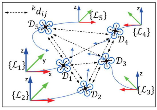
Figure 1.
Model of drone swarm.
After initializing the VINs (visual–inertial odometer system), it aligns its world coordinate system with the direction of gravity. Once UAVs complete their own initialization, their world coordinate system coincides on the Z axis, and each coordinate axis only differs in translation and the yaw angle, and then the 6DOF (degree of freedom) problem is transformed into a 4DOF problem.
represents the drones, and it is assumed that each member can obtain position information output by VIO at moment . The distance between the two drones and at time is denoted by . contains the translation and quaternion rotation of the VINs relative to the world coordinate system, and is denoted as follows:
Although the VINs can provide a relatively accurate coordinate of their own position, they still cannot sense the position of other members, and there is translation and rotation between each drone’s own body coordinate system. Let us assume that the IMU body frame of each drone is , and is the local frame after the first frame of VIN initialization is gravity-aligned. To locate in 3D space, the number of anchor nodes needs to be at least four, so the primary goal is to find the transformation relationship of the coordinate system between and , and we only need to find , which is represented as (1) due to gravity alignment.
Here, represents the yaw angle of each drone with respect to frame perpendicular to the Z-axis plane, and represents the translation of the origin of the other drone relative to frame . Let represent , which represents the world frame and navigator frame. Here, we introduce the concept of the navigator, who will be selected from the anchor nodes and will not undertake all the computational tasks; instead, all members will be built based on its frame after initialization. The distance between the two UAVs can be expressed as follows:
where means the Euclidean distance, which represents distances in three-dimensional space. In addition, we need to consider the relationship between the UWB installation position and the IMU position. However, since our UAVs share the same architecture, the positions of the UWB and IMU are fixed across different aircraft. Thus, any mechanical errors can be ignored during actual flight tests. There is an error between the measured value and the true value, and this error conforms to the Gaussian distribution, . We denote the measured value with , so we can surmise the following:
In addition to this, it is assumed that after the initialization, all members are represented as under the frame.
2.2. Anchor Node Configuration
For the quality of the cluster, there needs to be corresponding evaluation indicators [41]. When there is a large number of UAVs, calculation and communication become significant factors. If all members were to be initialized in the first step, the computational burden would increase exponentially due to the optimization problem. As the number of optimization parameters and constraints increases, the algorithm’s convergence speed will render the initialization algorithm unusable. Furthermore, the complex communication logic will also burden the system. Therefore, in order to reduce the computational burden of initialization, it is better to construct a relatively stable spatiotemporal datum. This paper proposes a fast initialization method for anchor nodes to provide a position initialization datum for other members. Selecting UAVs as anchor nodes for formations raises an important question. For traditional positioning methods like GPS, the configuration of the anchor node significantly impacts positioning accuracy. To analyze the positioning accuracy of UAV swarms, the CRLB is introduced. This section attempts to analyze the impact of the selection of different anchor nodes on the accuracy of the entire swarm from a theoretical level and provide the best suggestions for the selection of anchor nodes. Meanwhile, the D2 anchor selection method will be discussed.
The CRLB provides the lower bound of the variance of the parameter estimates, and for arbitrary unbiased estimators, its covariance matrix satisfies the following:
where is the Fisher information matrix, which is defined as
In our scenario, represents the position parameter of the drone, and is the observation data, assuming that the position of different nodes in a unified coordinate system is known, and the node position is denoted as . Then,
A simulation is carried out according to the above formula. The simulation results are shown in Figure 2, where it can be seen that the error caused by the configuration factor of the measured node is as small as possible, and the best position is located in the center of the anchor node; thus, when initializing, the UAV at the edge position should be selected as the anchor node for initialization, and the optimal position distribution of the anchor node can be obtained, minimizing the uncertainty of the overall position estimation.
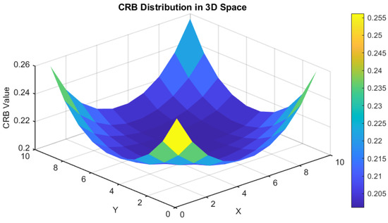
Figure 2.
FIM (Fisher information matrix) simulation analysis.
In order to reduce computational load, we have developed a strategy for screening anchor nodes. These nodes will be chosen to take part in the subsequent optimization of the positioning. When selecting anchor nodes, we will take into account the distribution of different members in 3D space in order to choose the best anchor node that is as close to the CRLB as possible. To achieve this, we will use a method named D2, which involves summing distances to assess the significance of each point, wherein the point with the greatest distance will be chosen as the optimal anchor node. When the algorithm begins, the sum of distances from all other members will be calculated for each member , as the marginality evaluation index:
where represents the evaluation index of member . Next, we select the first four members with the largest distance and as the optimal anchor nodes. It is expressed as follows:
The first four members are chosen as the best anchor nodes because their positions are as close as possible to the CRLB in the entire cluster. This helps to enhance the accuracy of cluster positioning. The method takes into account the distribution of members in 3D space and assesses the sum of their distances from other members to determine the optimal anchor node, thereby maximizing the positioning accuracy of the entire cluster. Through simulation tests, the experimental results are depicted in Figure 3, confirming that the anchor nodes chosen by the method align with the theoretical optimal nodes.
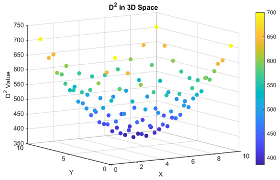
Figure 3.
D2 algorithm simulation analysis.
The optimal strategy for siting UAVs was used to select four UAVs as the anchor nodes for subsequent spatial datum establishment, including navigators. Moreover, it is important to consider the impact of anchor node selection on the configuration accuracy, as well as the timing of when the algorithm starts. In practical scenarios, the algorithm should initiate when the motion configuration is optimal. To address this, two criteria are introduced. Firstly, we observe the motion offset of all Z-axis members compared to the other two axes. If the offset is significantly large, this indicates that the members are taking off, and we calculate the singularity of the matrix. For instance, during the few seconds when the plane is in the air, most drones ascend vertically, causing the motion configuration to result in a singular matrix and a non-rigid distance matrix of motion [36].
2.3. Non-Convex Optimization Problems
After choosing the initial anchor node, we need to optimize its position. During the drone initialization process, the IMU constrains the gravity direction, enabling each drone to perceive its pitch and roll angles. However, due to observability limitations, it is not possible to standardize the heading angles between all members using the IMU. The actual ranging is obtained from UWB ranging, and the error is assumed to follow a Gaussian distribution. The true relative distance is obtained from Equation (5), but in practice, the robot-to-robot distance will be affected by noise measurements, causing the calculated distance to be different from the true distance. This process is based on the initialization method for two members as described in the literature [38,42]. Firstly, a weighted least squares problem is established, which is then transformed into a QCQP (quadratically constrained quadratic program) problem. The square distance residuals can be expressed as follows:
where
represents the actual measurement, and we obtain a weighted least squares problem,
where , is a matrix of covariance, and the two measurements are independent of each other, so that , where refers to the rows and columns in the matrix. The calculation method of the is referred to in paper [38], so . Further, we will turn the WLS problem into a QCQP problem, as described in Appendix A for the specific process. We can then obtain a quadratic constraint quadratic optimization problem.
Here, is a nine-dimensional column vector with five constraints added for the two-member case. Up to this point, they have only considered the scenario where two drones measure each other, as presented in paper [38]. This approach sacrifices accuracy in favor of faster computation speed by transforming the QCQP problem into a semi-definite programming (SDP) problem. However, given that our algorithm runs on the host processor, maintaining the accuracy of the anchor node is crucial for overall precision. Therefore, we opt to retain the QCQP solution method. In Section 2.5, we will delve into how to convert this approach into a convex optimization problem for multi-drone measurements.
2.4. Multi-Dimensional Scale Transformation
In UAV swarms, accurately positioning each node is crucial for collaborative swarm tasks. Although multi-dimensional scaling (MDS) is a commonly used method for node positioning, the traditional MDS algorithm has limitations in terms of large computation and slow convergence speed when dealing with large-scale networks. The traditional MDS algorithm [18] assumes that all nodes only know the ranging values of each other.
We suppose that , where refers to the UWB measurements matrix at times ,
which is the Eigenvalue decomposition of matrix . Then, becomes
Then, we have
Traditional MDS algorithms are computationally intensive and time-consuming when processing large-scale data because they rely on singular value decomposition (SVD) for solutions. This paper simplifies the SGD-SMACOF algorithm proposed in paper [37], aiming to improve the computational efficiency and accuracy of node positioning. The SMACOF algorithm realizes the MDS of nodes by iteratively optimizing the stress function. The stress function is defined as follows:
The proof process is shown in Appendix B, and the final iteration formula is as follows:
where is the learning rate parameter and is the generalized inverse matrix. We stop iterating if or a certain iteration limit is reached. As shown in Figure 4, it has significant advantages over DC-MDS.
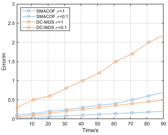
Figure 4.
The simulation results of the improved SMACOF algorithm compared with the DC-MDS algorithm.
2.5. Fast Swarm Collaborative Positioning Algorithm
This method in [38] works well with a small number of clusters, but the number of computations grows at a rate of . Based on this, we have developed a more comprehensive four-member initialization unit, focusing on addressing situations with more than five UAVs in a swarm. Drawing inspiration from the base station localization algorithm [43], we believe that anchor node positioning provides a solid solution with a mature research foundation. Thus, our primary focus is on resolving the precise positioning relationship between anchor nodes. The entire algorithm flow is illustrated in Figure 5. It begins with VIO initialization, followed by selecting the appropriate time for initialization, choosing anchor nodes, initializing anchor nodes, and finally achieving global positioning.
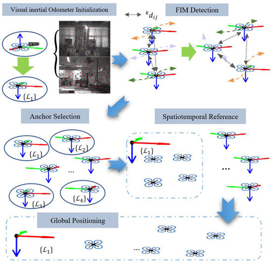
Figure 5.
Algorithm flowchart of this paper.
If frame is the navigator, then the unknown quantities between the anchor nodes are This approach would result in excessive information redundancy and a huge amount of computation. Moreover, the calculation mode requires special consideration, whether one member receives all the data for the settlement, or two members calculate each other and finally spread the calculation results by broadcasting. The former will cause a drone to receive a huge amount of information that cannot be processed, and the latter will reduce the timeliness of information between members. We consider sending and receiving data together through multi-machine communication and UWB communication, processing all data through the host, and then returning the calculation results to all members. This solves the problem of computing power and enables the host to have the ability to control all members in a centralized manner. Moreover, in our method, only limited data are passed during member communication. Thesis [20] requires the host to have stronger computing power and greatly increases the communication burden, which is not suitable for large-scale networks, while our network greatly reduces the communication burden.
Based on paper [38], we improved the non-convex QCQP problem, converted the unknown quantity of the four members, and added an unknown quantity from , as shown in Figure 6, so that a stable geometric relationship is formed, as shown in Figure 6, so that we have an additional constraint relation. The simulation results show that adding a relative ranging is helpful for improving the overall accuracy. We make the appropriate transformation so that the order of the solutions becomes .
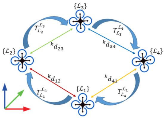
Figure 6.
A model of solving the anchor problem.
In order to represent the algorithm more clearly, we simplify the symbol in Equation (15). Here, does not represent members, but rather the number of columns; denotes the nine-dimensional unknown in column , such as ; denotes the corresponding weight matrix; denotes the set of all anchor node unknowns; and the optimization goal is to minimize the quadratic sum of all unknown vectors weighted by their respective matrices.
For such a geometrically closed-loop vector shown in Figure 6, there are the following properties:
Therefore, in order to ensure the physical and geometric constraints of the optimization problem, we introduce the following new constraints under the original constraints:
and
where corresponds to the number of constraints, . The optimization variable is a matrix of position vectors for all drones:
Combining the above objective functions and constraints, the complete optimization problem can be formulated as follows:
This is a quadratic non-convex optimization problem with linear and quadratic constraints, so it can be solved by a standard convex optimization algorithms library, such as the interior point method and gradient descent method; this paper uses the CVX of MATLAB and the CVXPY library in Python to simulate them, respectively. The simulation results are similar in accuracy, and the results will be given in the next section.
During the initial value stage, to achieve faster convergence, we will use the data from the gyroscope and magnetic compass in the UAV flight controller as the initial values. This allows the other three anchor nodes and the navigator to establish the translation and rotation relationship of the coordinate system between each other. Essentially, the four anchor nodes can restore the transformation relationship of the coordinate systems of other members. Additionally, the distance matrix is available and the algorithm in Section 2.4 can be used to obtain the relative translation relationship between all coordinate systems. The positional relationship between the members is restored through the anchor node. Assuming that Y is the recovery coordinate with the possibility of arbitrary rotation translation and is the result of the initialization of the anchor node, all member positions can be obtained by a simple transformation.
Now, only the heading angle has not been restored. At this time, the original 4DOF problem becomes a 1DOF problem. After performing another step of least squares on the remaining members, the rotation of the coordinate system is restored for all members. At this stage, we are able to determine the translation and rotation relationships between all coordinate systems and accurately understand the relative positions of all members. Our primary focus in this paper is not on large-scale swarm attitude information but rather on obtaining precise position information for each point within the swarms. The pseudocode for the algorithm flow is presented in Algorithm 1.
| Algorithm 1. Cooperative Increasing SAM Algorithm |
| ; 1: FIM Detection 3: Anchor Selection 4: Select anchor nodes based on the FIM detection results by using (11). 5: Improved QCQP 6: Determine the translation and rotation between all anchor nodes by using (28) 7: Quick SMACOF 9: Relative to Absolute Transformation |
3. Results
The experimental section of this paper is split into two parts: swarm simulation and actual flight experiments. These experiments aim to demonstrate the effectiveness and superiority of the proposed method in various environments. The focus is on the accuracy of UAV swarm initialization (RMSE), trajectory overview, and the analysis of time complexity and errors related to different algorithms.
3.1. Simulations
This study aims to test the proposed fast initialization method’s performance across different numbers of UAV swarms through detailed swarm simulation experiments. The simulation experiments are conducted on a computer equipped with an Intel i5-9300H CPU, 16GB RAM, RTX 1650 GPU, and Windows 11 system. The simulation experiments were carried out in MATLAB. Two sets of experiments are performed: one with 10 sorties and one with 50 sorties, representing small-scale and large-scale UAV swarm initialization processes in a satellite signal rejection environment, respectively. This study compares four different initialization algorithms: nonlinear least squares (NLS) [44], semidefinite programming (SDP), the SOTA quadratic convex optimization problem (QCQP) proposed in paper [38], and the method proposed in this paper.
Within the simulation, each drone utilizes a visual–inertial odometer and UWB sensors to mimic real-world sensor data acquisition. The visual–inertial odometer provides relative displacement trajectories over time, while the UWB sensors measure the distance between drones. To replicate sensor noise in a real environment, Gaussian noise is incorporated into the VIO data, with the standard deviation of the noise set based on the performance parameters of the actual sensor. The simulation utilizes . Gaussian noise is also introduced to the UWB ranging data to simulate ranging errors in practical applications: .
The initial conditions and iterations of each optimization algorithm were fine-tuned through multiple experiments to ensure a fair comparison of different algorithms. For the NLS algorithm, the initial position value is in the positive direction of the x-axis, the distance corresponds to the UWB measurement, and the number of iterations is set to 200. For the SDP algorithm, the maximum number of iterations is also set to 200. Finally, for the QCQP algorithm, the initial position value is in the positive direction of the x-axis, the distance corresponds to the UWB measurement, and the maximum number of iterations is set to 200.
In a simulation environment, 10 and 50 UAVs are randomly distributed in a three-dimensional space. They follow preset trajectory patterns such as circular, rectangular, elliptical, straight, triangular, and a crossed Figure 7. Each trajectory can be adjusted for different parameters including height, size, speed, and opening/closing angles. During the simulation, the UAVs move according to these different shapes and at various altitudes. The trajectory of each UAV is created using VIO data, and the distance matrix between UAVs is obtained using UWB ranging. To ensure a fair comparison, algorithms using NLS, SDP, QCQP, and our proposed algorithm are run independently on the same dataset. Each algorithm is tested for accuracy, convergence time, and performance with varying numbers of drones. Additionally, the true value of the drones is represented in the same coordinate system, with each drone’s VIO measurements starting from the (0,0,0) point. The analysis involves evaluating the RMSE between true and estimated values 60 s after takeoff, with flight speeds ranging from 1 to 5 m/s, and the time taken for each algorithm to converge.
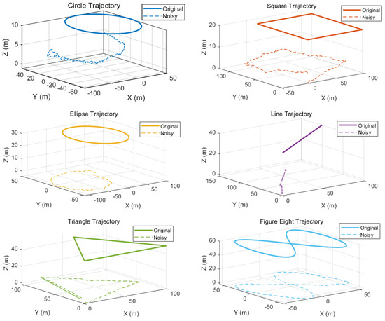
Figure 7.
The different trajectories used in the simulation experiment.
The experiment results are shown in Table 1 and Figure 8. The algorithm has a slightly slower performance than the SDP algorithm when the number of UAVs is small, but it has similar accuracy to QCQP. The algorithm’s advantages become more evident when the number of UAVs is large, especially after exceeding 15 UAVs. Thanks to an optimization step, the algorithm maintains consistent computational efficiency regardless of the number of drones. In addition, due to the high accuracy of the QCQP algorithm, the proposed algorithm consistently delivers precise results. Two important metrics to note are the convergence time, which is the time required for the convergence of non-convex optimizations, and time cost, representing the total time needed from the start of the algorithm until the recovery of the coordinate axis. The total time may vary due to the re-computation of the optimization problem or non-convergence issues.

Table 1.
The results of the simulation experiment.
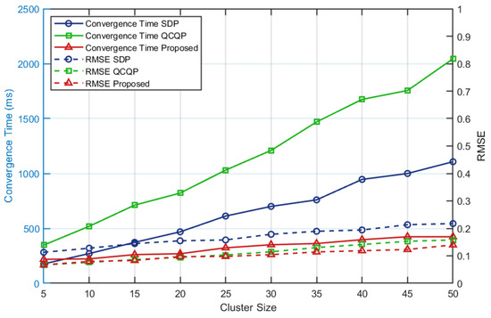
Figure 8.
Simulation results. The solid line in the figure represents the influence of different numbers of drones on the convergence time of the algorithm, and the dotted line represents the impact of different numbers of drones on the accuracy of the algorithm.
3.2. Real-World Experiments
Each drone is equipped with an IMU, a stereo camera, and a UWB sensor. The IMU captures the drone’s motion information, the camera captures visual data, and the UWB measures the distance between drones. To speed up the initial setup process, initial values use data from calibrated gyroscopes and magnetic compasses. The drone used in the experiment was a modified Amu drone, shown in Figure 9a, with a 250 mm frame. It is equipped with a Jetson TX2 processor, Pixhawk 6c mini flight controller, zed mini camera, and NoopLoop’s LinkTrack S series UWB. The flight-data-processing computer is the same as the emulation computer.
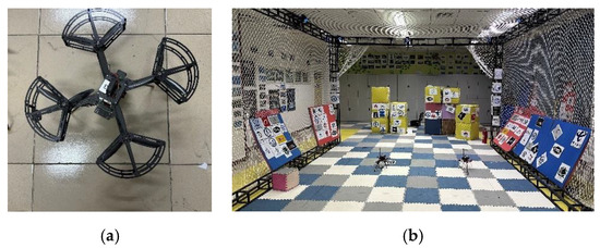
Figure 9.
(a) The quadrotor platforms used in our experiments; (b) the flight site used in our experiment.
In the experiment, the drone’s connection with the computer was established through ROS1 multi-machine communication, and the frequency of VIO data output was set to 100 Hz. A FZMotion Mocap System with eight cameras running at 120 Hz was used. According to the technical specifications and the reported accuracy from the FZMotion software, the positioning accuracy can reach 0.05 mm/m. Since this accuracy is two orders of magnitude smaller than the expected accuracy of the VIO-UWB system, it was deemed sufficient for use as the ground truth measurement. The UWB ranging can achieve a refresh rate of 50 Hz for 10 members in practical applications. The sensor data of each UAV are locally recorded through ROSBAG, and all the bags are centrally processed by the computer to simulate multi-drone communication. Before each experiment, the drones are randomly distributed in the field, and they follow a fixed flight trajectory at an approximate altitude for approximately 100 s. The first 60 s of flight data are selected for later analysis. The flight trajectories recorded by VIO and motion capture are aligned, as shown in Figure 10 and Figure 11. The yaw angles of the four anchor nodes are transformed and time-aligned, as shown in Figure 10. Figure 11 shows the VIO and motion capture trajectories of the seven members after time alignment.
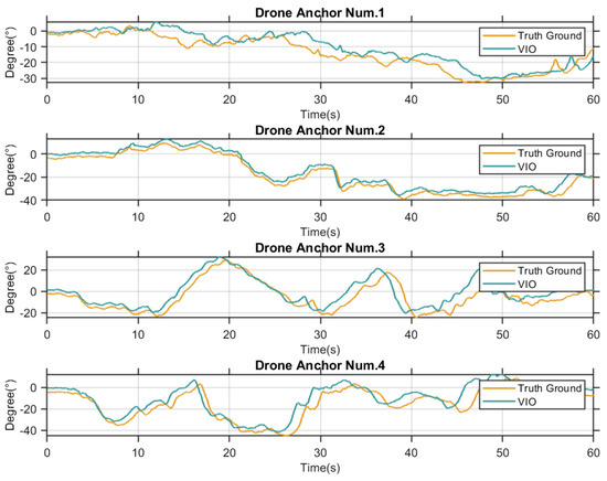
Figure 10.
The yaw angle of the anchor node is the result after time alignment. The yellow line represents the true value, and the green line represents the result of the VIO output.
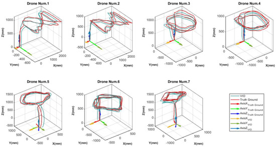
Figure 11.
The trajectories of the anchor node are the result after time alignment. The red line represents the true value, and the blue line represents the result of the VIO output.
In the analysis, we used the NLS, SDP, and QCQP algorithms for initialization calculations based on the collected data. Each algorithm independently ran on the same dataset to ensure a fair comparison. We recorded and compared the calculation time, RMSE, and trajectory error of each algorithm for analysis.
In our analysis, we have compared the effectiveness of our anchor node algorithm with that of the algorithm presented in paper [38]. The results are displayed in Table 2. Our algorithm demonstrates considerable improvement in the success rate, attributed to the assistance of the gyroscope and the initial value of the magnetic compass. Our algorithm ensures a fundamentally guaranteed success rate, with similar absolute errors in translation and significantly reduced time consumption.

Table 2.
The experimental results for anchor node initialization.
Please see the full experimental results in Figure 12 and Figure 13 and Table 3. The operation time and average time here refer to the time after takeoff, and the takeoff process is not included in these times. The trend of the experiment results was similar to that of the simulation. In Figure 12, we analyze the time required to solve different algorithms, and the results are consistent with those in Figure 8 from the simulation. It is important to note that the time analyzed is for the algorithm’s convergence, not the complete algorithm. Figure 13 illustrates the comparison between estimated and true values during flight. Our algorithm demonstrates significantly faster performance than the QCQP algorithm, with accuracy comparable to that of the QCQP. In summary, we have achieved a solution accuracy close to that of the current state-of-the-art algorithm [38], but in less time.
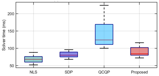
Figure 12.
Solver time of different algorithms. The green boxes represent nonlinear least squares (NLS); the purple box represents semidefinite programming (SDP); the light blue box represents the quadratic convex optimization problem (QCQP); and the red box represents the method proposed in this paper.
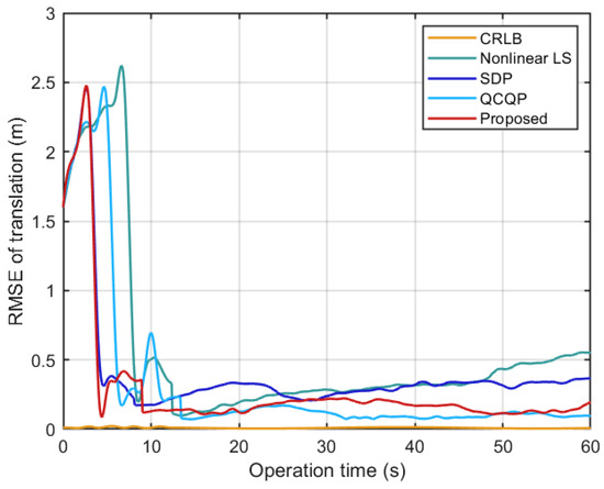
Figure 13.
Estimation results in our experiment.

Table 3.
Experimental results for different algorithms.
4. Discussion
Combined with simulation and real-world experiments, the accuracy of the original QCQP algorithm is higher than that of the algorithm we proposed. Still, this advantage will be greatly weakened by the time consumption when the number of clusters increases. Comparing the simulation results, we can see that the time cost of the QCQP method is positively correlated with the number of members, while the time consumption of our method is not directly related to the number of members, so the increase in time consumption will offset the advantage of the accuracy of the QCQP method. In addition, we consider that the UAV swarm should be as fast and accurate as possible; in fact, in the experiment, we can find that the accuracy of our QCQP method is comparable, which is significantly better than other SDP and NLS methods, and combined with the lower time consumption, our method is still very competitive, especially in the initialization stage of large-scale swarms. We used a priori information based on gyroscopes and magnetic compasses in this work. This means that for all members of the cluster, we can obtain a very precise initial value of the attitude without using GPS. By ensuring the accuracy of the initial value, we can achieve a very high success rate of convergence. This indicates that the algorithm is very robust.
5. Conclusions
In this paper, we propose a two-stage initialization method based on VIO and ranging to effectively solve the problem of the rapid initialization of UAV swarms in satellite signal rejection environments. Both theoretical simulations and real-world tests show that the proposed method has high precision and robustness, providing crucial support for the application of UAV swarms in complex environments. The method also has shortcomings. Our experiments do not meet the flight test of large-scale UAVs, so for more than 10 UAVs, it is still in the stage of simulation experiments. In addition, the algorithm has high requirements for time synchronization, this algorithm adopts a hard synchronization strategy and is not optimized for the time difference between different devices, and we are currently carrying out research and experiments on time synchronization problems. You can also try an asynchronous approach. In short, the algorithm still has limitations, but it is still competitive in the current initialization method due to its speed, robustness, and high precision. In future work, our focus should be on improving the algorithm’s solution speed without sacrificing accuracy. Additionally, this algorithm should be used in conjunction with mature path-planning algorithms to maximize its utility.
Author Contributions
Conceptualization, R.W. and Z.D.; methodology, R.W.; software, R.W.; validation, R.W.; formal analysis, R.W.; investigation, R.W.; resources, R.W.; data curation, R.W.; writing—original draft preparation, R.W.; writing—review and editing, R.W.; visualization, R.W.; supervision, Z.D.; project administration, R.W. All authors have read and agreed to the published version of the manuscript.
Funding
This research received no external funding.
Data Availability Statement
The study did not report any data.
Conflicts of Interest
The authors declare no conflicts of interest.
Appendix A
In this section, we will go into detail about how to translate Equation (14) into a QCQP problem. is expanded to obtain
where , and if we make
Later, we simplify it to
For the squared distance error between members and , can be re-expressed as
where . At this moment, Equation (14) can be re-expressed as follows:
Eventually, Equation (14) is transformed into a non-convex QCQP problem:
We re-express the algorithm in paper [38] with complex notation in order to expand from two-drone to multi-drone, and to express the QCQP problem more concisely, we simplify to , to .
Appendix B
We divide the stress function into three parts:
In paper [45], is the measurement distance, is the Euclidean distance of node and node under frame, and is the weight for weighting the measurement accuracy, which we set to 1 in the application of this paper. The second part of the stress function is decomposed into matrix form to make it easy to process and optimize:
where , and for each matrix , −1 at , and 0 elsewhere.
Here, is the Laplace matrix based on the weight matrix . For the third part, it is rewritten in matrix form using the Cauchy–Schwartz inequality
We define the matrix for updating
where is a small constant, ensuring that the formula is valid at .
The derivative of is calculated as a value with a derivative of 0,
After that, we can obtain
where [46]. We have simplified the algorithm in the algorithm of [37] so that the iteration formula is as follows:
Parameter µ acts as a learning rate and can be modified as needed. We use in experiments.
References
- Abdelkader, M.; Güler, S.; Jaleel, H.; Shamma, J.S. Aerial Swarms: Recent Applications and Challenges. Curr. Robot. Rep. 2021, 2, 309–320. [Google Scholar] [CrossRef] [PubMed]
- Peksa, J.; Mamchur, D. A Review on the State of the Art in Copter Drones and Flight Control Systems. Sensors 2024, 24, 3349. [Google Scholar] [CrossRef]
- Chandran, I.; Vipin, K. Multi-UAV Networks for Disaster Monitoring: Challenges and Opportunities from a Network Perspective. Drone Syst. Appl. 2024, 12, 1–28. [Google Scholar]
- Fascista, A. Toward integrated large-scale environmental monitoring using WSN/UAV/Crowdsensing: A review of applications, signal processing, and future perspectives. Sensors 2022, 22, 1824. [Google Scholar] [CrossRef]
- Ming, R.; Jiang, R.; Luo, H.; Lai, T.; Guo, E.; Zhou, Z. Comparative Analysis of Different UAV Swarm Control Methods on Unmanned Farms. Agronomy 2023, 13, 2499. [Google Scholar] [CrossRef]
- Radoglou-Grammatikis, P.; Sarigiannidis, P.; Lagkas, T.; Moscholios, I. A Compilation of UAV Applications for Precision Agriculture. Comput. Netw. 2020, 172, 107148. [Google Scholar] [CrossRef]
- Castrillo, V.U.; Manco, A.; Pascarella, D.; Gigante, G. A review of counter-UAS technologies for cooperative defensive teams of drones. Drones 2022, 6, 65. [Google Scholar] [CrossRef]
- Li, Z.; Jiang, C.; Gu, X.; Xu, Y.; Cui, J. Collaborative positioning for swarms: A brief survey of vision, LiDAR and wireless sensors based methods. Def. Technol. 2024, 33, 475–493. [Google Scholar] [CrossRef]
- Yang, B.; Yang, E. A survey on radio frequency based precise localisation technology for UAV in GPS-denied environment. J. Intell. Robot. Syst. 2021, 103, 38. [Google Scholar] [CrossRef]
- Lin, J.; Wang, Y.; Miao, Z.; Zhong, H.; Fierro, R. Low-complexity control for vision-based landing of quadrotor UAV on unknown moving platform. IEEE Trans. Ind. Inform. 2021, 18, 5348–5358. [Google Scholar] [CrossRef]
- Vödisch, N.; Unal, O.; Li, K.; Van Gool, L.; Dai, D. End-to-end optimization of LiDAR beam configuration for 3D object detection and localization. IEEE Robot. Autom. Lett. 2022, 7, 2242–2249. [Google Scholar] [CrossRef]
- Li, J.; Bi, Y.; Li, K.; Wang, K.; Lin, F.; Chen, B.M. Accurate 3D localization for MAV swarms by UWB and IMU fusion. In Proceedings of the 2018 IEEE 14th International Conference on Control and Automation (ICCA), Anchorage, AK, USA, 12–15 June 2018; pp. 100–105. [Google Scholar]
- Rubina, A.; Artemenko, O.; Andryeyev, O.; Mitschele-Thiel, A. A novel hybrid path planning algorithm for localization in wireless networks. In Proceedings of the 3rd Workshop on Micro Aerial Vehicle Networks, Systems, and Applications, New York, NY, USA; 2017; pp. 13–16. [Google Scholar]
- Retscher, G. Fundamental concepts and evolution of Wi-Fi user localization: An overview based on different case studies. Sensors 2020, 20, 5121. [Google Scholar] [CrossRef] [PubMed]
- Zhang, J.; Wang, X.; Yu, Z.; Lyu, Y.; Mao, S.; Periaswamy, S.C.; Patton, J.; Wang, X. Robust RFID based 6-DoF localization for unmanned aerial vehicles. IEEE Access 2019, 7, 77348–77361. [Google Scholar] [CrossRef]
- Tiemann, J.; Wietfeld, C. Scalable and precise multi-UAV indoor navigation using TDOA-based UWB localization. In Proceedings of the 2017 International Conference on Indoor Positioning and Indoor Navigation (IPIN), Sapporo, Japan, 18–21 September 2017; pp. 1–7. [Google Scholar]
- Liu, J.; Pu, J.; Sun, L.; He, Z. An approach to robust INS/UWB integrated positioning for autonomous indoor mobile robots. Sensors 2019, 19, 950. [Google Scholar] [CrossRef] [PubMed]
- Wang, R.; Deng, Z. Co-Operatively Increasing Smoothing and Mapping Based on Switching Function. Appl. Sci. 2024, 14, 1543. [Google Scholar] [CrossRef]
- Tong, P.; Yang, X.; Yang, Y.; Liu, W.; Wu, P. Multi-UAV collaborative absolute vision positioning and navigation: A survey and discussion. Drones 2023, 7, 261. [Google Scholar] [CrossRef]
- Schmuck, P.; Ziegler, T.; Karrer, M.; Perraudin, J.; Chli, M. Covins: Visual-inertial slam for centralized collaboration. In Proceedings of the 2021 IEEE International Symposium on Mixed and Augmented Reality Adjunct (ISMAR-Adjunct), Bari, Italy, 4–8 October 2021; pp. 171–176. [Google Scholar]
- Feng, D.; Qi, Y.; Zhong, S.; Chen, Z.; Jiao, Y.; Chen, Q.; Jiang, T.; Chen, H. S3e: A large-scale multimodal dataset for collaborative slam. arXiv 2022, arXiv:2210.13723. [Google Scholar]
- Lajoie, P.-Y.; Beltrame, G. Swarm-slam: Sparse decentralized collaborative simultaneous localization and mapping framework for multi-robot systems. IEEE Robot. Autom. Lett. 2023, 9, 475–482. [Google Scholar] [CrossRef]
- Tian, Y.; Chang, Y.; Arias, F.H.; Nieto-Granda, C.; How, J.P.; Carlone, L. Kimera-multi: Robust, distributed, dense metric-semantic slam for multi-robot systems. IEEE Trans. Robot. 2022, 38, 2022–2038. [Google Scholar] [CrossRef]
- Xu, H.; Zhang, Y.; Zhou, B.; Wang, L.; Yao, X.; Meng, G.; Shen, S. Omni-swarm: A decentralized omnidirectional visual–inertial–uwb state estimation system for aerial swarms. IEEE Trans. Robot. 2022, 38, 3374–3394. [Google Scholar] [CrossRef]
- Xu, H.; Liu, P.; Chen, X.; Shen, S. D2SLAM: Decentralized and Distributed Collaborative Visual-inertial SLAM System for Aerial Swarm. arXiv 2022, arXiv:2211.01538. [Google Scholar]
- Peng, Z.; Xu, Y.; Yan, M.; Yin, W. Arock: An algorithmic framework for asynchronous parallel coordinate updates. SIAM J. Sci. Comput. 2016, 38, A2851–A2879. [Google Scholar] [CrossRef]
- Arafat, M.Y.; Alam, M.M.; Moh, S. Vision-based navigation techniques for unmanned aerial vehicles: Review and challenges. Drones 2023, 7, 89. [Google Scholar] [CrossRef]
- Mazhar, F.; Khan, M.G.; Sällberg, B. Precise indoor positioning using UWB: A review of methods, algorithms and implementations. Wirel. Pers. Commun. 2017, 97, 4467–4491. [Google Scholar] [CrossRef]
- Hapsari, G.I.; Munadi, R.; Erfianto, B.; Irawati, I.D. Future Research and Trends in Ultra-Wideband Indoor Tag Localization. IEEE Access 2024, 1. [Google Scholar] [CrossRef]
- Elsanhoury, M.; Mäkelä, P.; Koljonen, J.; Välisuo, P.; Shamsuzzoha, A.; Mantere, T.; Elmusrati, M.; Kuusniemi, H. Precision positioning for smart logistics using ultra-wideband technology-based indoor navigation: A review. IEEE Access 2022, 10, 44413–44445. [Google Scholar] [CrossRef]
- Xu, H.; Wang, L.; Zhang, Y.; Qiu, K.; Shen, S. Decentralized visual-inertial-uwb fusion for relative state estimation of aerial swarm. In Proceedings of the 2020 IEEE international conference on robotics and automation (ICRA), Paris, France, 31 May–31 August 2020; pp. 8776–8782. [Google Scholar]
- Cao, Y.; Beltrame, G. VIR-SLAM: Visual, inertial, and ranging SLAM for single and multi-robot systems. Auton. Robot. 2021, 45, 905–917. [Google Scholar] [CrossRef]
- Xie, J.; He, X.; Mao, J.; Zhang, L.; Hu, X. C2VIR-SLAM: Centralized collaborative visual-inertial-range simultaneous localization and mapping. Drones 2022, 6, 312. [Google Scholar] [CrossRef]
- Nguyen, T.-M.; Yuan, S.; Cao, M.; Nguyen, T.H.; Xie, L. Viral slam: Tightly coupled camera-imu-uwb-lidar slam. arXiv 2021, arXiv:2105.03296. [Google Scholar]
- Nguyen, T.-M.; Nguyen, T.H.; Cao, M.; Qiu, Z.; Xie, L. Integrated uwb-vision approach for autonomous docking of uavs in gps-denied environments. In Proceedings of the 2019 International Conference on Robotics and Automation (ICRA), Montreal, QC, Canada, 20–24 May 2019; pp. 9603–9609. [Google Scholar]
- Queralta, J.P.; Li, Q.; Schiano, F.; Westerlund, T. VIO-UWB-based collaborative localization and dense scene reconstruction within heterogeneous multi-robot systems. In Proceedings of the 2022 International Conference on Advanced Robotics and Mechatronics (ICARM), Guilin, China, 9–11 July 2022; pp. 87–94. [Google Scholar]
- Zou, Y.; Hu, E.; Deng, Z.; Jin, C. Multidimensional Scaling Algorithm for Mobile Swarming UAVs Localization. IEEE Trans. Intell. Veh. 2023, 1–11. [Google Scholar] [CrossRef]
- Nguyen, T.H.; Xie, L. Relative transformation estimation based on fusion of odometry and UWB ranging data. IEEE Trans. Robot. 2023, 39, 2861–2877. [Google Scholar] [CrossRef]
- Qin, T.; Li, P.; Shen, S. Vins-mono: A robust and versatile monocular visual-inertial state estimator. IEEE Trans. Robot. 2018, 34, 1004–1020. [Google Scholar] [CrossRef]
- Qin, T.; Cao, S.; Pan, J.; Shen, S. A general optimization-based framework for global pose estimation with multiple sensors. arXiv 2019, arXiv:1901.03642. [Google Scholar]
- Zaitseva, E.; Levashenko, V.; Mukhamediev, R.; Brinzei, N.; Kovalenko, A.; Symagulov, A. Review of Reliability Assessment Methods of Drone Swarm (Fleet) and a New Importance Evaluation Based Method of Drone Swarm Structure Analysis. Mathematics 2023, 11, 2551. [Google Scholar] [CrossRef]
- Trawny, N.; Roumeliotis, S.I. On the global optimum of planar, range-based robot-to-robot relative pose estimation. In Proceedings of the 2010 IEEE International Conference on Robotics and Automation, Anchorage, AK, USA, 3–7 May 2010; pp. 3200–3206. [Google Scholar]
- Wymeersch, H.; Lien, J.; Win, M.Z. Cooperative localization in wireless networks. Proc. IEEE 2009, 97, 427–450. [Google Scholar] [CrossRef]
- Ziegler, T.; Karrer, M.; Schmuck, P.; Chli, M. Distributed formation estimation via pairwise distance measurements. IEEE Robot. Autom. Lett. 2021, 6, 3017–3024. [Google Scholar] [CrossRef]
- De Leeuw, J.; Mair, P. Multidimensional Scaling Using Majorization: SMACOF in R; University of California, Los Angeles(UCLA): Los Angeles, CA, USA, 2011. [Google Scholar]
- Yang, B.; Chen, R.; Li, B.; Li, C. Multi-vehicle cooperative positioning based on edge-computed multidimensional scaling. China Commun. 2021, 18, 53–63. [Google Scholar] [CrossRef]
Disclaimer/Publisher’s Note: The statements, opinions and data contained in all publications are solely those of the individual author(s) and contributor(s) and not of MDPI and/or the editor(s). MDPI and/or the editor(s) disclaim responsibility for any injury to people or property resulting from any ideas, methods, instructions or products referred to in the content. |
© 2024 by the authors. Licensee MDPI, Basel, Switzerland. This article is an open access article distributed under the terms and conditions of the Creative Commons Attribution (CC BY) license (https://creativecommons.org/licenses/by/4.0/).