Abstract
This paper develops a framework for geolocating a ground moving target with images taken from an unmanned aerial vehicle (UAV). Unlike the usual moving target geolocation approaches that rely heavily on a laser rangefinder, multiple UAVs, prior information of the target or motion assumptions, the proposed framework performs the geolocation of a moving target with monocular vision and does not have any of the above restrictions. The proposed framework transforms the problem of moving target geolocation to the problem of stationary target geolocation by matching corresponding points. In the process of corresponding point matching, we first propose a Siamese-network-based model as the base model to match corresponding points between the current frame and the past frame. Besides the introduction of a base model, we further designed an enhanced model with two outputs, where a row-ness loss and a column-ness loss are defined for achieving a better performance. For the precision of corresponding point matching, we propose a compensation value, which is calculated from the outputs of the enhanced model and improves the accuracy of corresponding point matching. To facilitate the research on corresponding point matching, we constructed a dataset containing various aerial images with corresponding point annotations. The proposed method is shown to be valid and practical via the experiments in simulated and real environments.
1. Introduction
Unmanned aerial vehicles (UAVs) are increasingly being deployed for a wide variety of missions, including surveillance and reconnaissance [1,2,3,4]. UAV-based computer vision capabilities, such as target detection [5,6,7] and tracking [8,9,10], play particularly important roles in the above missions. However, it is not sufficient to simply detect and track a target; we often need to know the three-dimensional position of the moving target. In this paper, target geolocation refers to the process of using UAVs to obtain target information and estimate the position of the target in the world coordinate system. In the process, a global positioning system (GPS) and attitude and heading reference system (AHRS) are used to acquire the UAV’s position and attitude for the geolocation in real time; the UAV’s navigation state and the target’s image are acquired simultaneously. There are many methods used for geolocating moving targets. The most commonly used methods are laser-based methods [11,12], which can geolocate arbitrary moving targets but are not suitable for small UAVs due to the weight of the laser rangefinder. Therefore, many methods do not utilize a laser rangefinder but rely heavily on the prior information of the moving target. For example, some methods [13,14] use the elevation information provided by a digital elevation model (DEM) to estimate the position of moving target. In addition, some other methods [15,16,17] need the size of the target in advance to estimate the depth information of the target according to the imaging principle. There are also methods [18] for performing moving target geolocation that do not require the above constraints but require the target to move according to a given motion assumption, such as uniform linear motion. These methods require the information of the moving target to be obtained before geolocation, which cannot be applied to geolocate unknown targets. To avoid the above limitations, an alternative solution is to utilize multiple UAVs to take multiple images of a moving target at the same time, following which, the three-dimensional position of the moving target can be estimated by employing multiview geometry [19] and using only image information. However, utilizing multiple UAVs will have some issues, such as an expensive cost, collaborative control and data synchronization, which do not exist in the scene of utilizing a single UAV. In conclusion, it is crucial to develop a moving target geolocation method that utilizes only a single UAV and does not have the limitations mentioned above.
In this research, we developed a novel ground moving target geolocation framework based on monocular vision using a UAV platform, and the constructed system is shown in Figure 1. It avoids the utilization of the rangefinder and is free from the aforementioned constraints, such as prior information and the given motion model, and uses only aerial image sequences and the UAV navigation state to achieve high-precision geolocation for a moving target on the ground. In summary, the main contributions of our work are as follows:
- •
- To avoid the limitations of the traditional methods, we propose a novel moving target geolocation framework based on monocular vision. In this method, we designed a learning-based corresponding point matching model to address the challenge of using multiview geometry based on monocular vision to geolocate a moving target.
- •
- We then analyzed the shortcomings of the base model and further propose an enhanced model with two outputs, where a row-ness loss and a column-ness loss are defined to achieve a better performance. Moreover, we propose a coordinate mapping method that greatly reduces the error of corresponding point matching.
- •
- For the evaluation of the proposed framework, on the one hand, we constructed a dataset containing various aerial images with corresponding point annotations that can be used for training and evaluating the proposed learning-based models; on the other hand, the effectiveness of the proposed method was verified via the experiments in simulated and real environments.

Figure 1.
Demonstration that the proposed framework realizes online ground moving target geolocation using a UAV platform.
2. Related Work
2.1. Moving Target Geolocation
In recent years, scholars have conducted a considerable amount of research on moving target geolocation. In general, target geolocation methods can be divided into three categories: one-shot methods, methods based on multiview geometry and methods based on target motion assumptions.
The one-shot methods utilize only one image of the moving target but require the relative distance or relative altitude between the UAV and the target. There are many ways to obtain the relative distance or relative altitude. Some researchers utilized a DEM to obtain the relative altitude between the UAV and the target. Qiao et al. [20] showed that a vision-based tracking system could estimate the coordinates of a moving target in real time with a gimbal-stabilized camera, but an accurate DEM is required to obtain the target’s altitude. Alternatively, some researchers estimated the relative distance based on the size of the target in the image. Zhang et al. [16] proposed a relative distance estimation method based on the prior information of the target that required the size of the target to be known, and then used the geometric relationship to calculate the distance between the UAV and the target. Zhu et al. [17] showed that their learning-based method could estimate the distance to a specific target. Nevertheless, their experimental results showed that the distance estimation methods based on prior information work well only if the target is close, and are not suitable for accurately geolocating ground targets with UAVs. Han et al. [21] provided a method for calculating the height of the UAV above a target using computer vision, but this method assumes that the altitude of the target does not change. Zhang et al. [22] also estimated the height of the UAV above a target, but they assumed that the target was stationary when estimating the relative altitude. In practical applications, the distance from the UAV to the target is usually determined by a laser rangefinder, which has the highest accuracy among the abovementioned methods [11]. However, the use of laser-based methods for the continuous geolocation of moving targets will greatly reduce the flight time of UAVs due to the weight of the laser rangefinder. It is worth noting that the abovementioned methods were susceptible to the random measurement errors of the UAV’s navigation state because only one image of the target is taken at each target geolocation.
To avoid the limits of the abovementioned methods, some researchers utilized multiple UAVs to simultaneously acquire multiple images of moving targets and estimate the position by multiview geometry. Bai et al. [19] proposed a binocular-vision-based method that uses two UAVs to estimate the target’s position and uses Kalman filter technology to improve the accuracy of the target geolocation. Wang et al. [23] also utilized multiple UAVs to geolocate a moving target and presented a nonlinear filter based on solving the Fokker–Planck equation to address the issue of the time delay during data transmission. Xu et al. [24] proposed a method for adaptively adjusting the weights according to the position of the UAVs, which can improve the accuracy of the results of the weighted least squares. Although these methods using multiple UAVs estimated the position of the moving target utilizing the image information, they also brought problems, such as an expensive cost, collaborative control and data synchronization.
To geolocate the moving target using monocular vision, some researchers have utilized multiple target motion assumptions to solve the metric scale of the target trajectory. Avidan et al. [25] provided a solution where at least five views are required if the motion of the target is constrained to a straight line and where at least nine views are required if the object is moving with conic trajectories. Yow et al. [26,27] proposed a system that instructs the UAV to fly in a specific pattern to achieve a large baseline and then uses multiple images to estimate the trajectory equation of the target. Unfortunately, the methods utilizing multiple target motion assumptions have difficulty meeting the requirements of practical applications because we cannot instruct the non-cooperative target to move according to the assumed motion.
In this research, we proposed a ground moving target geolocation framework based on monocular vision using a UAV platform. Unlike the abovementioned methods that heavily rely on a laser rangefinder, multiple UAVs, prior information of the target or motion assumptions, it only utilizes images sequences and the UAV’s navigation state to geolocate the ground moving target. The proposed framework utilizes multiple remote sensing images and then establishes nonlinear observation equations to solve the target position, which improves the precision of the target geolocation.
2.2. Corresponding Point Matching
The image points of the same three-dimensional position in different images are called corresponding points. Simultaneous localization and mapping (SLAM) implements a process of matching corresponding points that utilizes the epipolar search and batch matching methods, which take advantage of the features of the corresponding points to match them [28]. However, there are some differences in the scene of the moving target geolocation. The corresponding point in the current frame and the corresponding point in the past frame have different feature information, because the corresponding point in the current frame is covered by the target. Therefore, the method in SLAM does not work in the scene of the moving target geolocation. For this, we first propose a learning-based base model that takes advantage of the environmental feature information around the target. Considering the shortcomings of the base model, we further designed an enhanced model with two outputs, where a row-ness loss and a column-ness loss are defined to achieve a better performance. Moreover, we introduced a coordinate mapping compensation value, which greatly reduces the error of coordinate mapping.
3. Methods
The proposed monocular vision-based moving target geolocation framework is illustrated in Figure 2. The framework utilized only a sequence of images to estimate the three-dimensional coordinates of a ground moving target. The data acquisition process used a UAV equipped with a monocular camera, GPS and AHRS to obtain the images of moving target and the navigation state of UAV simultaneously. The target detection method was used to detect the ground moving target in the latest image (current frame image). Then, the current frame image where the target has been detected and past frame images were used to match corresponding points by the proposed learning-based model. Corresponding point matching was used to find the corresponding points of the target point in the current frame from the past frames. It is worth noting that these images used to perform geolocation must satisfy the baseline constraints; that is, the distance between the positions of the UAV corresponding to two adjacent images must be greater than the length of the baseline. The length of the baseline was calculated as follows: first, according to the observation equation in [22], rough target geolocation results can be obtained. Rough geolocating estimation requires the relative altitude between UAV and target, which can be obtained according to the position of the UAV and the target at the last moment. Then, the rough pixel position of the target in each past frame is calculated according to Equation (1) until the past frame image is found, in which, the pixel position of the target is at the edge of the image.
where M is the projection matrix, which includes the internal and external parameters when taking the past frame images. Finally, the length of the baseline can be obtained according to Equation (2).
where is the distance from the current UAV’s position to the UAV’s position when taking the image , and N is the number of images used to perform geolocation.
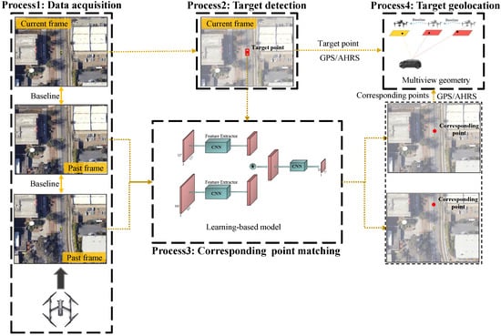
Figure 2.
Overview of the proposed moving target geolocation framework using monocular vision.
After that, pieces of data required for moving target geolocation have been acquired. Each piece of data contains the corresponding point’s coordinate provided by target detection or corresponding point matching, the UAV’s position provided by GPS and the UAV’s attitude in navigation frame n provided by AHRS. Finally, the three-dimensional coordinates of moving target can be estimated from these data utilizing multiview geometry.
As shown in Figure 3, is the UAV’s position at different time, is the corresponding point and P is the three-dimensional position of moving target. and determine a line of sight and pieces of data determine lines of sight. The intersection of these lines of sight is the three-dimensional position of the target. A line of sight can be expressed as
where is the three-dimensional coordinates of target. The rotation matrix represents the transformation from camera frame b to navigation frame n. The camera’s pose in UAV’s body frame and the UAV’s pose in navigation frame are the parameters necessary for calculating the rotation matrix . We assumed that the camera is fixedly mounted on the UAV in this paper, so the camera’s pose in UAV’s body frame is a fixed vector. Therefore, at least two images are required for estimating the three-dimensional coordinates of moving target, and using more images results in more reliable results from the least squares model.
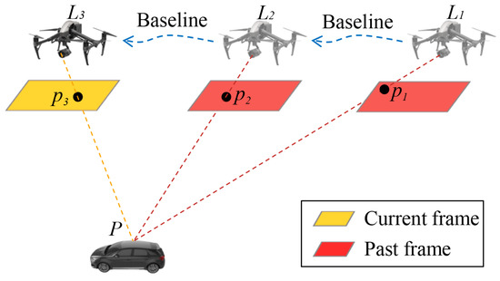
Figure 3.
Multiview geometry based on monocular vision.
In summary, the proposed moving target geolocation framework utilizes images and UAV navigation state to construct a multi-view geometric model to estimate the coordinates of moving targets. Corresponding point matching is a key process in the proposed framework, for which, we propose a base model and an enhanced model.
3.1. Base Model
In the corresponding point matching module, we first propose a learning-based base model that takes advantage of the environmental feature information around the target to match the corresponding points. As shown in Figure 4, our base model consists of two components, i.e., a Siamese subnetwork and a center-ness subnetwork.
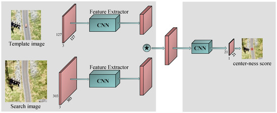
Figure 4.
Our base model pipeline. Green boxes denote the CNN structure. Red boxes denote feature maps. The left side is a Siamese subnetwork with a depthwise correlation layer (denoted by ⋆) for multichannel feature map extraction. The right side shows the center-ness subnetwork for corresponding point matching, which is taken to decode the position information of the corresponding point from the feature map.
3.1.1. Siamese Subnetwork
The Siamese subnetwork consists of two branches: a target branch, which takes the template image Z as its input, and a search branch, which takes the search image X as its input. The two branches share the same convolutional neural network (CNN) architecture as their backbone structure, which maps the input images to the same feature space. The template image Z is an image of size ( in this paper) extracted from the current frame, and the center of Z is the target’s position. The search image X is extracted from the previous frame. It is not feasible to utilize the feature information of the target in the current frame to match the corresponding point in the previous frame because the target is moving between multiple measurements. In this model, we took advantage of the environmental information around the target; therefore, this approach requires the size of the template image to be much larger than the size of the target for abundant environmental information.
Corresponding point matching was used to accurately locate the point that we are looking for in the previous frame. Low-level features such as edges, corners, colors and shapes that represent better visual attributes are indispensable for corresponding point matching, which does not require high-level semantic information. Hence, we utilized the same AlexNet as [29] as our backbone network. To retain abundant information for the center-ness subnetwork, we used a depthwise correlation layer to embed the information of the two feature maps and and produce multiple similarity maps:
where ⋆ denotes the channel-by-channel correlation operation. The sizes of and are and , respectively. The size of R is .
3.1.2. Center-Ness Subnetwork
The head network incorporates only a center-ness branch to output the center-ness score of each point in response map . Here, w and h ( in this paper) represent the width and height of the response map, respectively. Each point in the response map can be mapped to a point in the search image. The center-ness score of represents how close the point is to the corresponding point. There is a bounding box in the search image centered on the corresponding point and of the same size as the template image. The definition of the center-ness score is related to the bounding box as follows: on the one hand, the score of is set to 0 if is outside of the bounding box in the search image. On the other hand, the closer is to the corresponding point, the higher the score of if is inside the bounding box. Therefore, the center-ness score in is defined by
where represent the distances from point to the four sides of the bounding box in the search image. We denote the coordinates of the top-left and bottom-right corners of the bounding box in the search image as and , respectively. are defined by
is an indicator function defined by
It can be judged whether point is inside or outside the bounding box by Equation (7). The center-ness loss is defined as
3.2. Enhanced Model
Although our base model can find the corresponding point from a given search image, it still has some shortcomings, as described below. To further improve the accuracy of corresponding point matching, we first analyzed the shortcomings of the base model and then modified the model based on these analyses.
In summary, the shortcomings of the base model are as follows:
- •
- Blank area in search image. A long baseline threshold (the distance between position and position in Figure 3) is beneficial for improving the accuracy of target geolocation. In practical applications, we chose as long a threshold as possible, which caused the corresponding points to be at the edges of previous frames. The base model takes the search patch X centered on the corresponding point as its input. In this case, a large area in the search patch X is blank, which reduces the accuracy of corresponding point matching.
- •
- Unreliable scoring mechanism. In the inference phase of the base model, the point with the highest score in the response map is selected and mapped back to the search image. It is unreliable to determine the final result from only the highest scoring point due to the imperfect accuracy of the model. It is worth mentioning that, in the base model, the error of 1 pixel in the response map is approximately equal to the error of 24 pixels in the original image.
- •
- Error in coordinate mapping. In the base model, the point with the highest score is selected and mapped back to the search image as a result. However, the sizes of the response map and search image are and , respectively, which means that the points in the response map can only be mapped to a subset of points in the search image and that the corresponding point may not be in the subset.
Motivated by the aforementioned analyses, we propose an enhanced CPointNet model with three inputs for the superior matching of corresponding points. As shown in Figure 5, our enhanced model consists of three parts: a Siamese subnetwork with three inputs, a row-ness subnetwork and a column-ness subnetwork.
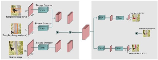
Figure 5.
Our CPointNet pipeline. Green boxes denote the CNN structure. Red boxes denote feature maps. The left side is a Siamese subnetwork with three input branches, a depthwise correlation layer (denoted by ⋆) for multichannel response map extraction and a concatenation layer (denoted by +) for producing multiple similarity maps. The right side shows a row-ness subnetwork for row prediction, a column-ness subnetwork for column prediction and a center-ness subnetwork for strengthening constraint.
3.2.1. Siamese Subnetwork
The Siamese subnetwork consists of three branches: a row branch that takes the template image as input, a column branch that takes the template image as input and a search branch that takes the search image X as input. The three branches share the same CNN architecture as their backbone model, similar to the base model. The template images and are patches of size extracted from the current frame. Before generating the template image , a bounding box of size () centered on the target must be determined, and then the width of the bounding box must be extended to the left or right according to the position of the target in the current frame so that the size of the bounding box becomes . The center of the template image is the center of the bounding box. The template image is also an image of size extracted from the current frame. Before generating the template image , we also determined a bounding box of size centered on the target and then extended the height of the bounding box to the top or bottom according to the position of the target in the current frame so that the size of the bounding box becomes . The center of the template image is the center of the bounding box. In this way, the model no longer takes advantage of the feature information around the target but utilizes the feature information around the row and column where the target is located. This solves the first problem of the base model. For example, when the corresponding point is located near the left edge of the image, the width of the bounding box in can be extended to the right to retain abundant feature information.
After extracting features through the backbone network, feature maps , and were obtained. We considered and to be two convolution kernels used to perform depthwise correlations with , and then performed a concatenation operation on the two obtained feature maps to produce multiple similarity maps R:
where + denotes a concatenation operation. The size of R is .
3.2.2. Row-Ness and Column-Ness Subnetwork
The head subnetwork consists of two branches: a row-ness branch that outputs the row-ness score for each point in and a column-ness branch that outputs the column-ness score for each point in . Each position in or can be mapped back onto the search image as . The higher the score or , the closer the point is to the row or column where the corresponding point is. Then, through the response maps and , the row and column of the corresponding point, respectively, can be determined. Different from the base model, we can calculate the row and column coordinates in a more stable way. For example, we summed the scores in the response map by row and then selected the row with the maximum value as the result. The scores and are defined by
We assigned 1 to if position is in the bounding box and 0 if not. The row-ness loss is
The column-ness loss is
In the enhanced model, the row-ness and column-ness branches work independently; as a result, the intersection of row and column may not be the position of the corresponding point, especially in scenes with repeating textures. Therefore, we still took advantage of the center-ness loss, as shown in (14), to strengthen the constraint:
where is defined by
The overall loss function is
where the constants and are the weights for the column-ness loss and center-ness loss, respectively. During model training, we empirically set and .
3.2.3. Compensation Value of Coordinate Mapping
The or scores indicate how close the position is to the row or column where the corresponding point is located, not the probability of the position being the corresponding point. The position with the highest score is the closest to the row or column of the corresponding point. Therefore, selecting the row or column with the highest score as the row or column of the corresponding point will produce large errors. To obtain more accurate results, we propose coordinate mapping compensation. In the response map , we summed the scores by row and averaged them to obtain a new response map in which each score corresponds to the mean value of the scores of one row in the response map . According to Equation (10), if row has the highest score and its corresponding row in the search image is the row of the corresponding point, should be equal to . However, if row is above the row where the corresponding point is located, should be less than . According to the definitions of scores and , we propose the compensation value of coordinate mapping as
where s is the total stride of the backbone ( in this paper). Therefore, row in the response map corresponds to row in the search image, and column in the response map corresponds to column in the search image.
4. Evaluation
In this section, we evaluate the proposed learning-based models and the moving target geolocation framework with CPointNet. First, we introduce the proposed dataset for corresponding point matching and evaluate the base model and enhanced model in the dataset. Then, we verify the effectiveness and superiority of the proposed geolocation framework with CPointNet in the simulated environment. Finally, we further verify the effectiveness of the proposed framework in the real environment.
4.1. Learning-Based Model
We implemented the base and enhanced models using the popular deep learning platform PyTorch, and ran them on a machine with Intel(R) i7-10700 @2.90GHz CPU(Intel Coporation, California) and NVIDIA RTX 2070 Super GPU (NVIDIA Corporation, California).
4.1.1. Training and Test Datasets
One of the main challenges of training neural networks for corresponding point matching tasks is the lack of the dataset containing aerial images in which the corresponding points are annotated. For this, we obtained aerial images from Google Earth Studio and manually labeled the corresponding points, as shown in Figure 6. The camera optical axis is always perpendicular to the horizontal plane when taking a sequence of images, which is consistent with the scene of geolocation.
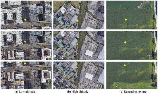
Figure 6.
Examples of our dataset. (a,b) are the images taken by the camera at low and high altitude, respectively. (c) is the image with repeating texture. The image points marked with “+” represent the corresponding points.
We collected 200 video sequences, each containing 25 images, for a total of 5000 images. We annotated a point on each image for a total of 5000 points. Any two frames of images in the same video sequence can be regarded as one piece of data for a total of 60,000 pieces of data. These pieces of data were divided into 45,000 piece of training data and 15,000 pieces of test data. During the training process, the position of the corresponding point in the template image will be covered by a mask with a random shape and color as shown in Figure 7 because there is a moving target in the sequence images captured by the UAV in practical applications but not in the collected dataset.
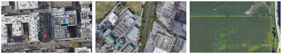
Figure 7.
Examples of masks with random shape and color.
4.1.2. Results on the Test Dataset
In Figure 8, we show the whole matching process. With the outputs of row-ness and column-ness subnetworks, a row location r and a column location c were obtained. To achieve a more stable and accurate result, the compensation values were computed through Equations (17) and (18), which were added to r and c, respectively, to produce the final matching result.
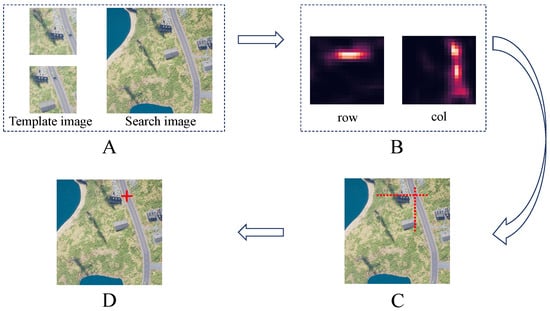
Figure 8.
Matching process. Subfigure (A) shows a pair of template images and a search image as inputs, while (B) presents the outputs of the model. (C) shows the predicted row and column of the corresponding point. (D) shows the final result after adding the compensation values to the row and column in (C).
Our goal was to search for the corresponding point and locate it in the previous frame, which is a similar task to locating the center of the bounding box in target detection and tracking. Therefore, we adopted the precision provided by [30] and the average error of corresponding point matching on the test dataset as our evaluation metrics. Currently, no method exists that matches corresponding points in moving target geolocation scenarios. In this paper, we compared the performances of the base model and CPointNet. Figure 9 shows the matching results of the base model and CPointNet in the challenging cases.
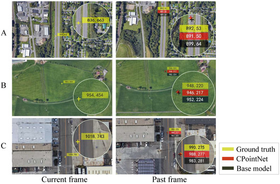
Figure 9.
Comparisons of the proposed base model and CPointNet on three challenging sequences from the test dataset. Subfigure (A) shows the case where the corresponding point is located at the edge of the previous frame. In case (B), the images have repeating texture. In case (C), the images are captured by the camera at low altitude.
For our proposed model, we utilized the same AlexNet as [31] as the feature extractor for both the base model and the enhanced model. We trained our models for 30 epochs with a batch size of 64 on the training dataset.
In this subsection, we first perform an ablation study with the base model as the baseline to identify the key component for improving the performance of matching.
The results are shown in Table 1. We gradually updated the base model by applying the three input branches, the compensation value and the center-ness loss to strengthen the constraint to yield CPointNet, and compared their average error () of corresponding point matching. The key components for improving the matching performance can be listed in descending order as follows: the compensation value (2.53), the three input branches and improved head structure (2.16) and center-ness (0.48), where the contributed by each part is noted in parentheses. After adding all of the extra components into the base model, our CPointNet achieves a superior performance.

Table 1.
Ablation study: from the base model towards CPointNet. denotes the augmentation of . “Cen” for center-ness subnetwork, “Row” for row-ness subnetwork, “Col” for column-ness subnetwork and “Com” for compensation value.
In addition to comparing the average error, we also compared the precision of these models under different matching error thresholds. The results are shown in Figure 10a. Obviously, applying the compensation value greatly improves the accuracy of corresponding point matching. Additionally, it is worth mentioning that the three inputs, row-ness and column-ness are necessary conditions for applying the proposed compensation value. By comparing CPointNet and CPointNet without center-ness, it is obvious that, when the threshold is less than 6, their precision is almost the same, but when the threshold is greater than 6, their precision gap gradually increases. The reason for this phenomenon is that the center-ness can strengthen constraints and prevent the row-ness and column-ness from working independently.
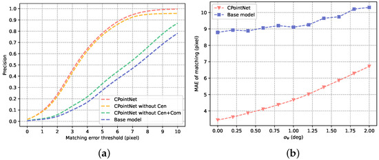
Figure 10.
Evaluation of CPointNet: (a) precision evaluation under different thresholds; (b) average error of matching under different heading angle measurement errors.
It is necessary to rotate the previous frame to keep the direction consistent with the current frame before matching corresponding points because CPointNet is not invariant to rotations. When geolocating a moving target, the optical axis of the camera should always be perpendicular to the ground, and the heading angle of the camera should be consistent with that of the UAV. Therefore, according to the heading angle of the UAV, the direction of the previous frame can be rotated to the direction of the current frame image. However, the matching result of the corresponding points is affected by the error in the UAV’s heading angle measurement. Under a different standard deviation of the heading angle measurement error, the average matching errors of the base model and the enhanced model are shown in Figure 10b. We compared the average matching errors of the algorithms, while the mean value of the heading angle measurement error and the standard deviation were set to 0 and , respectively. Obviously, although CPointNet is more sensitive to the error of the heading angle measurement, the enhanced model still achieves a superior performance. It is worth mentioning that the UAV’s heading angle measurement error is generally within 1 degree.
4.2. Moving Target Geolocation Method
4.2.1. Evaluation in Simulation Environment
In this section, we evaluate the proposed moving target geolocation framework with CPointNet in Unreal Engine 4 (UE4) and Airsim simulation environments [29], as shown in Figure 11.
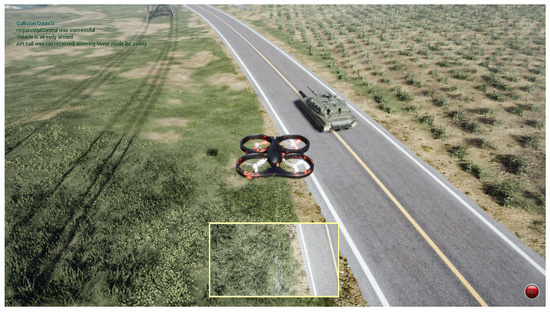
Figure 11.
Unreal Engine 4 (UE4) simulation environment.
Our goal is to use a UAV equipped with a monocular camera to geolocate a moving ground target with an arbitrary motion mode, and the optical axis of the camera is always perpendicular to the ground. The distance between the ground truth and the estimated target’s position is regarded as the geolocation error. We take the mean absolute error (MAE) of continuous geolocation when tracking the moving target as the evaluation metric.
As the comparison method, the one-shot method obtains the relative distance between the target and the UAV through the prior information [16] or the rangefinder, and then estimates the rotation matrix between the camera and the world coordinate system according to the attitude angle. In this experiment, we directly utilized the truth value of the relative distance to estimate the position of the moving target for the one-shot method. In the continuous geolocation process, the YOLOv5 target detecting algorithm [5] and the MOSSE target tracking algorithm [32] were used to determine the image point of the target that we are tracking in the current frame.
The main factors that affect the geolocation accuracy are the measurement errors of the UAV’s navigation state. Therefore, we evaluated the performance of the algorithms under different measurement errors of UAV’s attitude angle and position. In our proposed method, at least two images are required, and the greater the number of images, the more reliable the geolocation result due to least squares. In this experiment, we used two images, four images and six images, respectively, to estimate the position of the moving target and compare them with the one-shot method, which can only utilize one image for geolocation.
As shown in Figure 12a, we compared the mean absolute errors of the algorithms, while the mean value of the measurement error of the UAV’s heading angle and the standard deviation were set to 0 and , respectively. The standard deviations of the measurement errors of the pitch angle and the roll angle are both equal to . Obviously, as the standard deviation of the measurement error increases, the gap between the one-shot method and our method becomes larger. However, when the standard deviation is small, the one-shot method has a better performance than our proposed method, which is due to the matching error of the corresponding points. Figure 12a also demonstrates that multiple measurements can mitigate the matching error of the corresponding points and the error of the attitude angle measurement.
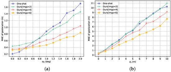
Figure 12.
Mean absolute error of geolocation under different conditions: (a) different attitude angle measurement errors; (b) different position measurement errors.
Moreover, we set and obtained the paths of the geolocation. As shown in Figure 13, the one-shot method has a more accurate estimation of the target’s elevation (Z coordinate). However, our method using six images can more accurately estimate the X coordinate and Y coordinate of the target because our method can use multiple observations to build a least squares model to mitigate the effects of Gaussian noise.
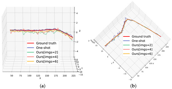
Figure 13.
Paths of geolocation when : (a) front view; (b) vertical view.
Likewise, we evaluated the performance of the algorithms under different measurement errors of the UAV’s position. As shown in Figure 12b, we set the mean value of the measurement error of the UAV’s altitude z to 0 and the standard deviation to and compared the mean absolute errors of two methods. The standard deviations of the measurement errors of x and y are both equal to , which is consistent with the actual situation. As the measurement error increases, the gap between the one-shot method and our method still increases. We set m and obtained the paths of the geolocation as shown in Figure 14. The paths show that our method with six images outperforms the one-shot method in X-coordinate estimation, Y-coordinate estimation and Z-coordinate estimation.
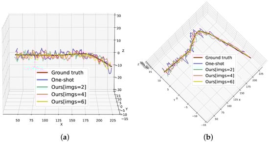
Figure 14.
Paths of geolocation when m: (a) front view; (b) vertical view.
As shown in Figure 12a,b, the performance of our proposed method improves as the number of images increases. However, as the number of images increases, the amount of time needed to geolocate the target also increases.
To further verify the effectiveness and robustness of the proposed framework, we set different flight altitudes and analyzed the geolocation errors of our method and the one-shot method. The indicators compared include the X-coordinate error, Y-coordinate error, Z-coordinate error and position error, considering three coordinates. In this comparison, our method utilized six images in each geolocation and the following assumptions in the measurement process were used, which are consistent with the actual situation: m and . Table 2 shows the geolocation errors of the two methods, including the mean absolute errors (MAEs) and standard deviations (STDs). It is shown in Table 2 that, with an increase in the flight altitude, the geolocation accuracy of the our method and the one-shot method decreases sharply. This is because the measurement errors of the UAV navigation state are very important for the two methods. When the flight altitude is small, the negative impact of the measurement errors on the two methods is not obvious, but the same measurement error will lead to a large positioning error when flying high. However, the Z-coordiante error of the one-shot method does not change significantly as the flight altitude increases. This is because the relative distance between the UAV and the target is the true value and the attitude measurement error of the UAV has little effect on the Z-coordinate error of the target because of the relative positional relationship between the UAV and the target. In contrast, the Z-coordinate error of our method increases when flying high. This is because our method takes the intersection of multiple lines of sight as the result of geolocation. The measurement error of the position and attitude will cause the change in the intersection of multiple lines of sight. It can be seen from Table 2 that the position error of our method is always less than that of the one-shot method, although the Z-coordinate error of our method is larger than that of the one-shot method when the flight altitude is 250 m and 300 m. It is worth mentioning that, in many tasks of geolocation, such as surveillance and reconnaissance, the Z-coordinate of the ground moving target is not required.
Table 2.
Statistical results of moving target geolocation.
In conclusion, the proposed framework can accurately estimate the position of the ground moving target at different flight altitudes. The X-coordinate error, Y-coordinate error and position error of our method consistently outperform the one-shot method, although the Z-coordinate error of our method is larger when flying high.
4.2.2. Evaluation in Real Environment
A real indoor experiment was also performed to further validate the proposed framework. The UAV used in this experiment was the laboratory product designed by our group as shown in Figure 15a. A camera was installed vertically downward on the UAV, so the attitude of the camera can be known from the attitude of the UAV. The UAV tracked the ground moving target as shown in Figure 15b and transmitted the pose information and acquired target images to the ground station in real time. The UAV and the ground station were run in the ROS system, and the precise position and attitude information of the UAV were provided by VICON (a motion capture system).
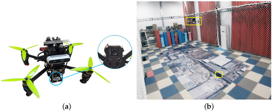
Figure 15.
Realistic experiment environment: (a) UAV with vertically downward camera; (b) moving target geolocation scene.
In this experiment, the important experimental parameters are shown in Table 3. The results of the realistic experiment are shown in Table 4. A total of 141 geolocations were performed while the UAV was tracking the ground moving target. Each geolocation needs to use four images. It shows that our method successfully achieves the geolocation of the ground moving target and that the absolute mean errors of the three coordinates are 0.046 m, 0.044 m and 0.165 m, respectively. When taking advantage of four images for geolocation, the FPS is 28, which still meets the real-time requirements.
Table 3.
Experimental parameters.
Table 4.
Geolocation results.
The realistic geolocation path is shown in Figure 16. The black path represents the actual position of the ground moving target obtained from VICON. The yellow path represents the position of the ground moving target obtained from our method. It can be seen that the path obtained by our method is undulating due to the influence of the Gaussian measurement error of the UAV’s navigation state. The abovementioned simulation experiments have demonstrated that our method can mitigate the effects of Gaussian measurement errors by utilizing the historical measurements.
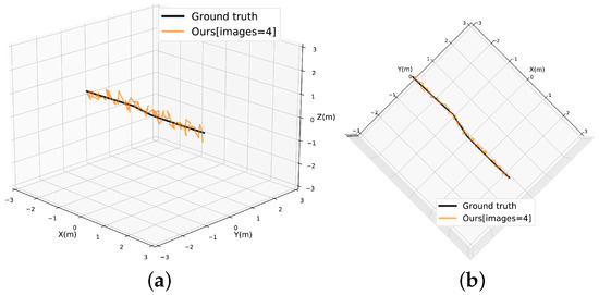
Figure 16.
Paths of geolocation: (a) front view; (b) vertical view.
The simulated and real experiments show that the proposed framework implements the function of geolocating the ground moving target using a UAV platform and does not rely on the rangefinder, multiple UAVs, prior information and motion assumptions. Compared with the commonly used one-shot method, the proposed framework can mitigate the effects of measurement errors of UAV’s position and attitude by using multiple measurement data.
5. Discussion
In order to solve the problem of using only monocular vision to geolocate the moving target, we propose a moving target geolocation framework based on corresponding point matching. Our method uses a two-step strategy to obtain the final result. The accuracy of the final result depends on two aspects: the matching accuracy of the corresponding point and estimation of target position. It can be seen from the experimental results shown in Figure 10 that the proposed corresponding point matching method can find the corresponding point from the search image. However, the performance of this method is affected by the measurement accuracy of the UAV attitude angle. In practical applications, the attitude angle measurement error of UAV is generally within 1 degree, but for a UAV with a low-quality sensor, its attitude angle measurement may have a greater system error.
After that, we evaluated the geolocation performance of the proposed method. For Gaussian measurement errors, obtaining more measurement data is the most effective method for mitigating the influence of Gaussian measurement errors. However, we do not simply increase the number of UAVs to obtain more observation data. If so, the cost will be higher and the system will be extremely complex. Our strategy is to make historical measurement data able to be used to estimate the current position of the moving target through corresponding point matching. From the experimental results in Figure 12, Figure 13 and Figure 14 and Table 2, we can see that our method can mitigate the influence of Gaussian measurement errors very well. In contrast, the one-shot method is easily affected by the Gaussian measurement error because it can only use one set of measurement data.
In practical application, the state measurement error of a UAV is an important factor affecting the geolocation accuracy of the moving target. The experimental results show that the proposed method can effectively mitigate the influence of the UAV state measurement error on the moving target geolocation accuracy. However, the limitation of our method is that corresponding point matching requires the use of image background information, which is difficult to achieve in some scenes with simple background information (such as the geolocation of a moving target on the sea). Therefore, our next research plan is to develop a more general geolocation method.
6. Conclusions
In this paper, we discuss the significant but challenging problem of monocular-vision-based moving target geolocation. This is the first attempt to utilize the matching of corresponding points for the geolocation of moving targets. For this task, we introduced a base model to directly match corresponding points in the current frame and previous frames. Moreover, we designed an enhanced model with three inputs and proposed a coordinate mapping compensation value for a more precise estimation. To facilitate research on this task, we constructed a dataset that can be used for corresponding point matching. The experimental results demonstrate that the proposed enhanced model can accurately match corresponding points and that the moving target geolocation framework with CPointNet has a better performance than the most commonly used one-shot method.
For further work, we will solve the problem of the CPointNet model proposed in this paper not being rotation invariant. In addition, we will try to use self-supervised methods to train the model to solve the problem of the lack of a dataset.
Author Contributions
Conceptualization, B.D. and J.G.; methodology, T.P.; software, T.P.; validation, J.G.; formal analysis, H.D.; investigation, H.D. and B.Z.; resources, T.P.; data curation, J.G.; writing—original draft preparation, T.P.; writing—review and editing, J.G. and H.D.; visualization, T.P.; supervision, B.D.; project administration, B.D.; funding acquisition, B.D. All authors have read and agreed to the published version of the manuscript.
Funding
This research was funded by National Natural Science Foundation of China, grant number 61902423.
Institutional Review Board Statement
Not applicable.
Informed Consent Statement
Not applicable.
Data Availability Statement
The data presented in this study have been shared to the public platform and can be found here: https://github.com/pantingwei/CP_Dataset (accessed on 5 December 2022).
Conflicts of Interest
The authors declare no conflict of interest.
References
- Wang, S.; Jiang, F.; Zhang, B.; Ma, R.; Hao, Q. Development of UAV-based target tracking and recognition systems. IEEE Trans. Intell. Transp. Syst. 2019, 21, 3409–3422. [Google Scholar] [CrossRef]
- Yun, W.J.; Park, S.; Kim, J.; Shin, M.; Jung, S.; Mohaisen, D.A.; Kim, J.H. Cooperative multiagent deep reinforcement learning for reliable surveillance via autonomous multi-UAV control. IEEE Trans. Ind. Inf. 2022, 18, 7086–7096. [Google Scholar] [CrossRef]
- Tsai, H.C.; Hong, Y.W.P.; Sheu, J.P. Completion Time Minimization for UAV-Enabled Surveillance over Multiple Restricted Regions. IEEE Trans. Mob. Comput. 2022. [Google Scholar] [CrossRef]
- Zhou, H.; Ma, Z.; Niu, Y.; Lin, B.; Wu, L. Design and Implementation of the UAV Reconnaissance System. In Advances in Guidance, Navigation and Control; Springer: Berlin/Heidelberg, Germany, 2022; pp. 2131–2142. [Google Scholar]
- Zhu, X.; Lyu, S.; Wang, X.; Zhao, Q. TPH-YOLOv5: Improved YOLOv5 based on transformer prediction head for object detection on drone-captured scenarios. In Proceedings of the IEEE/CVF International Conference on Computer Vision, Montreal, QC, Canada, 10–17 October 2021; pp. 2778–2788. [Google Scholar]
- Chen, C.; Zhang, Y.; Lv, Q.; Wei, S.; Wang, X.; Sun, X.; Dong, J. Rrnet: A hybrid detector for object detection in drone-captured images. In Proceedings of the IEEE/CVF International Conference on Computer Vision Workshops, Seoul, Republic of Korea, 27–28 October 2019; pp. 100–108. [Google Scholar]
- Zhan, W.; Sun, C.; Wang, M.; She, J.; Zhang, Y.; Zhang, Z.; Sun, Y. An improved Yolov5 real-time detection method for small objects captured by UAV. Soft Comput. 2022, 26, 361–373. [Google Scholar] [CrossRef]
- Hamdi, A.; Salim, F.; Kim, D.Y. Drotrack: High-speed drone-based object tracking under uncertainty. In Proceedings of the 2020 IEEE International Conference on Fuzzy Systems (FUZZ-IEEE), Glasgow, UK, 19–24 July 2020; pp. 1–8. [Google Scholar]
- Wen, L.; Zhu, P.; Du, D.; Bian, X.; Ling, H.; Hu, Q.; Zheng, J.; Peng, T.; Wang, X.; Zhang, Y.; et al. Visdrone-mot2019: The vision meets drone multiple object tracking challenge results. In Proceedings of the IEEE/CVF International Conference on Computer Vision Workshops, Seoul, Republic of Korea, 27–28 October 2019; pp. 189–198. [Google Scholar]
- Wen, L.; Du, D.; Zhu, P.; Hu, Q.; Wang, Q.; Bo, L.; Lyu, S. Detection, tracking, and counting meets drones in crowds: A benchmark. In Proceedings of the IEEE/CVF Conference on Computer Vision and Pattern Recognition, Nashville, TN, USA, 19–25 June 2021; pp. 7812–7821. [Google Scholar]
- Liu, C.; Liu, J.; Song, Y.; Liang, H. A novel system for correction of relative angular displacement between airborne platform and UAV in target localization. Sensors 2017, 17, 510. [Google Scholar] [CrossRef] [PubMed]
- Wang, X.; Liu, J.; Zhou, Q. Real-time multi-target localization from unmanned aerial vehicles. Sensors 2016, 17, 33. [Google Scholar] [CrossRef] [PubMed]
- El Habchi, A.; Moumen, Y.; Zerrouk, I.; Khiati, W.; Berrich, J.; Bouchentouf, T. CGA: A new approach to estimate the geolocation of a ground target from drone aerial imagery. In Proceedings of the 2020 4th International Conference on Intelligent Computing in Data Sciences (ICDS), Fez, Morocco, 21–23 October 2020; pp. 1–4. [Google Scholar]
- Xu, C.; Huang, D.; Liu, J. Target location of unmanned aerial vehicles based on the electro-optical stabilization and tracking platform. Measurement 2019, 147, 106848. [Google Scholar] [CrossRef]
- Namazi, E.; Mester, R.; Lu, C.; Li, J. Geolocation estimation of target vehicles using image processing and geometric computation. Neurocomputing 2022, 499, 35–46. [Google Scholar] [CrossRef]
- Gao, F.; Deng, F.; Li, L.; Zhang, L.; Zhu, J.; Yu, C. MGG: Monocular Global Geolocation for Outdoor Long-Range Targets. IEEE Trans. Image Process. 2021, 30, 6349–6363. [Google Scholar] [CrossRef] [PubMed]
- Zhu, J.; Fang, Y. Learning object-specific distance from a monocular image. In Proceedings of the IEEE/CVF International Conference on Computer Vision, Seoul, Republic of Korea, 27 October–2 November 2019; pp. 3839–3848. [Google Scholar]
- Dani, A.P.; Kan, Z.; Fischer, N.R.; Dixon, W.E. Structure and motion estimation of a moving object using a moving camera. In Proceedings of the 2010 American Control Conference, Baltimore, MA, USA, 30 June–2 July 2010; pp. 6962–6967. [Google Scholar]
- Bai, G.; Liu, J.; Song, Y.; Zuo, Y. Two-UAV intersection localization system based on the airborne optoelectronic platform. Sensors 2017, 17, 98. [Google Scholar] [CrossRef] [PubMed]
- Qiao, C.; Ding, Y.; Xu, Y.; Xiu, J. Ground target geolocation based on digital elevation model for airborne wide-area reconnaissance system. J. Appl. Remote Sens. 2018, 12, 016004. [Google Scholar] [CrossRef]
- Han, K.M.; DeSouza, G.N. Geolocation of multiple targets from airborne video without terrain data. J. Intell. Robot. Syst. 2011, 62, 159–183. [Google Scholar] [CrossRef]
- Zhang, L.; Deng, F.; Chen, J.; Bi, Y.; Phang, S.K.; Chen, X.; Chen, B.M. Vision-based target three-dimensional geolocation using unmanned aerial vehicles. IEEE Trans. Ind. Electron. 2018, 65, 8052–8061. [Google Scholar] [CrossRef]
- Wang, X.; Qin, W.; Bai, Y.; Cui, N. Cooperative target localization using multiple UAVs with out-of-sequence measurements. Aircr. Eng. Aerosp. Technol. 2017, 89, 112–119. [Google Scholar] [CrossRef]
- Xu, C.; Yin, C.; Huang, D.; Han, W.; Wang, D. 3D target localization based on multi–unmanned aerial vehicle cooperation. Meas. Control. 2021, 54, 895–907. [Google Scholar] [CrossRef]
- Avidan, S.; Shashua, A. Trajectory triangulation: 3D reconstruction of moving points from a monocular image sequence. IEEE Trans. Pattern Anal. Mach. Intell. 2000, 22, 348–357. [Google Scholar] [CrossRef]
- Kim, I.; Yow, K.C. Object location estimation from a single flying camera. UBICOMM 2015, 2015, 95. [Google Scholar]
- Yow, K.C.; Kim, I. General Moving Object Localization from a Single Flying Camera. Appl. Sci. 2020, 10, 6945. [Google Scholar] [CrossRef]
- Pizzoli, M.; Forster, C.; Scaramuzza, D. REMODE: Probabilistic, monocular dense reconstruction in real time. In Proceedings of the 2014 IEEE International Conference on Robotics and Automation (ICRA), Hong Kong, China, 31 May–7 June 2014; pp. 2609–2616. [Google Scholar]
- Shah, S.; Dey, D.; Lovett, C.; Kapoor, A. Airsim: High-fidelity visual and physical simulation for autonomous vehicles. In Field and Service Robotics; Springer: Berlin/Heidelberg, Germany, 2018; pp. 621–635. [Google Scholar]
- Guo, D.; Wang, J.; Cui, Y.; Wang, Z.; Chen, S. SiamCAR: Siamese fully convolutional classification and regression for visual tracking. In Proceedings of the IEEE/CVF Conference on Computer Vision and Pattern Recognition, Seattle, WA, USA, 13–19 June 2020; pp. 6269–6277. [Google Scholar]
- Bertinetto, L.; Valmadre, J.; Henriques, J.F.; Vedaldi, A.; Torr, P.H. Fully-convolutional siamese networks for object tracking. In Proceedings of the European Conference on Computer Vision, Amsterdam, The Netherlands, 11–14 October 2016; pp. 850–865. [Google Scholar]
- Bolme, D.S.; Beveridge, J.R.; Draper, B.A.; Lui, Y.M. Visual object tracking using adaptive correlation filters. In Proceedings of the 2010 IEEE Computer Society Conference on Computer Vision and Pattern Recognition, San Francisco, CA, USA, 13–18 June 2010; pp. 2544–2550. [Google Scholar]
Disclaimer/Publisher’s Note: The statements, opinions and data contained in all publications are solely those of the individual author(s) and contributor(s) and not of MDPI and/or the editor(s). MDPI and/or the editor(s) disclaim responsibility for any injury to people or property resulting from any ideas, methods, instructions or products referred to in the content. |
© 2023 by the authors. Licensee MDPI, Basel, Switzerland. This article is an open access article distributed under the terms and conditions of the Creative Commons Attribution (CC BY) license (https://creativecommons.org/licenses/by/4.0/).