Article

A Unmanned Aerial Vehicle (UAV)/Unmanned Ground Vehicle (UGV) Dynamic Autonomous Docking Scheme in GPS-Denied Environments

1
Department of Control Science and Engineering, College of Electronics and Information Engineering, Tongji University, Shanghai 201804, China
2
Shanghai Research Institute for Intelligent Autonomous Systems, Shanghai 201210, China
3
School of Electrical and Electronic Engineering, Nanyang Technological University, Singapore 639798, Singapore
*
Author to whom correspondence should be addressed.
Drones 2023, 7(10), 613; https://doi.org/10.3390/drones7100613
Submission received: 11 August 2023 / Revised: 9 September 2023 / Accepted: 22 September 2023 / Published: 29 September 2023

Abstract

:
This study designs a navigation and landing scheme for an unmanned aerial vehicle (UAV) to autonomously land on an arbitrarily moving unmanned ground vehicle (UGV) in GPS-denied environments based on vision, ultra-wideband (UWB) and system information. In the approaching phase, an effective multi-innovation forgetting gradient (MIFG) algorithm is proposed to estimate the position of the UAV relative to the target using historical data (estimated distance and relative displacement measurements). Using these estimates, a saturated proportional navigation controller is developed, by which the UAV can approach the target, making the UGV enter the field of view (FOV) of the camera deployed in the UAV. Then, a sensor fusion estimation algorithm based on an extended Kalman filter (EKF) is proposed to achieve accurate landing. Finally, a numerical example and a real experiment are used to support the theoretical results.

1. Introduction

Unmanned vehicles (UVs), which can be classified as unmanned ground vehicles (UGVs), unmanned aerial vehicles (UAVs), unmanned underwater vehicles (UUVs) and unmanned surface vehicles (USVs), depending on their working environments, are widely used in various fields. In particular, UAVs and UGVs play a major role in many practical applications due to their strong potential in high-risk missions. Leveraging their synergies in perception, communication, payload capacity and localization, they enhance a system’s overall capability, flexibility and adaptability to uncharted terrains, thereby accomplishing tasks that are arduous for a standalone UAV or solitary UGV. Primarily, they have important applications in the fields of intelligent transportation [1], urban cleanliness [2], unknown exploration [3], military [4,5], etc., and related research has been extensively carried out. It is worth noting that UAVs have played a significant role in the COVID-19 pandemic due to isolation security and telemedicine [6]. A prerequisite for accomplishing these tasks is to solve the localization problem of UAVs.
For the localization of a single unmanned system, many excellent works have appeared in recent years [7,8]. On the one hand, several methods have been based on infrastructure, which derives the location from distance information to anchors, such as GPS [9], motion capture system (MCS) [10], ultra-wideband (UWB) [11], etc. On the other hand, some on-board sensors (e.g., electro-optical devices [12], vision sensors [13,14] and laser scanners [15]) have been used to calculate the distance between the UAV and docking target in order to locate the target. The common knowledge is that GPS is cheap and relatively mature. However, when attempting to improve coverage or positioning accuracy in GPS-denied environments, there is a high installation cost, which may not be practical for many applications. On the other hand, on-board sensors, such as cameras and UWBs, have a limited field of view and range. Some research localizes the target by installing markers on the target and calculates the position of the markers by using on-board sensors or external installations [16,17], which, however, requires markers to meet certain requirements.
Compared to a single UV, multi-UV cooperation can achieve better efficiency and robustness in applications such as search and rescue, structure inspection, etc. Many studies have been conducted on single-domain UVs. For example, regarding UGVs, a Monte-Carlo-localization-based SLAM localization method for multiple unmanned vehicles was proposed in [18]. For the air domain, the UAV swarm employs a Bayesian compressed sensing (BCS) approach to estimate the location of ground targets from received signal strength (RSS) data collected by airborne sensors [19]. For automatic path planning, an algorithm based on adaptive clustering and an optimization strategy based on symbiotic biological search are used to effectively solve the path planning problem of UAVs [20]. In trajectory planning, non-causal trajectory optimization is exploited in a distance-only targeting method (i.e., based on distance and received signal strength) for multiple UAVs to achieve superior performance [21]. On the other hand, a combination of cross-domain UVs can greatly enlarge the operation space and enhance the capability of UVs.
Over the last decade, an increasing amount of scientific research on UAVs and UGVs has gradually turned to integrating them to accomplish a task, owing to their peculiar advantages. In this regard, the authors in [22] proposed a new cooperative system for UAVs and UGVs that not only provides more flexibility for aerial scanning and mapping through the UAV but also allows the UGV to climb steep terrain through the winding of tethers. In [23], at the Mohamed Bin Zayed International Robotics Challenge (MBZIRC) 2020, an autonomous UAV–UGV team was designed to solve an urban firefighting scenario for autonomous robots to foster and advance the state of the art in perception, navigation and mobile manipulation. In this problem, the critical premise of making good use of the complementary strengths of UAV–UGV to complete a task cooperatively is to obtain the absolute positions or relative positions of the UAV and UGV in an environment. In terms of autonomous localization, the authors in [24] proposed co-localization in an outdoor environment. The drone first mapped an area of interest and transferred a 2.5D map to the UGV. Ground robots achieve the attitude estimation of UAV poses by instantaneously registering a single panorama on a 2.5D map. In multi-domain missions, due to the limited endurance of the UAV, it faces a recovery problem, which is also called docking.
After obtaining a reliable relative localization, one can proceed to the next step: docking. In the literature, there has been a lot of mature work on static docking targets [25]. A guidance method is proposed that uses an airborne vision system for tracking infrared cooperative targets on board and inertial navigation to obtain attitude information for a UAV to land on a board [26]. Furthermore, the authors in [27] proposed a UWB-based facility where the UAV lands on a swinging mobile platform. A visual servo method for landing an autonomous UAV on a moving vehicle was designed without considering the infrastructure, with the limitation that the target needs to be present in the FOV. A dynamic docking scheme based on odometry and UWB measurements is proposed to overcome the field of view limitation and save computational costs [28,29]. Furthermore, considering a docking target without an odometer, an autonomous docking scheme based on UWB and vision with a uniform linear motion platform is proposed [30]. In these applications, docking is inefficient, and parties either have absolute positioning devices or conduct a large area of searches, which largely causes unnecessary deployment or computing costs. Docking targets are mostly cooperative or have uniform linear motions.
Therefore, the purpose of this study is to find a dynamic non-cooperative landing strategy using multi-sensor fusion to achieve precise docking for UAV/UGV in GPS-denied environments.
In summary, the main contributions of this study can be summarized as follows:
This study proposes a multi-sensor fusion scheme for UAV navigation and landing on a randomly moving non-cooperative UGV in GPS-denied environments.
In contrast to considering only distance measurement information at two time instants, this study selects measurements at multiple time instants to estimate the relative position and considers the case of measurement noise.
During the landing process, a landing controller based on position compensation is designed based on the fusion of distance measurement, vision and IMU positioning information.
Finally, the feasibility of the proposed scheme is verified and validated using a numerical simulation and a real experiment.
The rest of this paper is arranged as follows: In Section 2, the basic problem under study as well as the models of the UAV and target are given. In Section 3, the following work is detailed: (1) in the take-off phase, the rotation matrix and relative position of the initial test are calculated; (2) a navigation control algorithm for estimating relative position based on distance, velocity and displacement measurements is designed, and its convergence is proven; and (3) a multi-sensor fusion method based on EKF is proposed to estimate the relative position, and a position and attitude landing algorithm is designed. In Section 4, the experimental validation of the proposed method is presented. Finally, Section 5 concludes this paper.

2. Problem Formulation

For the docking problem, the proposed autonomous landing process consists of three phases: localization, navigation and landing. In the localization phase, the UAV calculates the relative position and translation matrix from the relevant data (linear velocity and angular velocity) of the UGV acquired during the take-off. When the UAV reaches the specified altitude, it can enter the navigation phase, and this study designs a distance- and odometer-based navigation trajectory control law. Once the UAV is close to the mobile platform and within the camera’s field of view (FOV) (i.e., the landing stage), the system will leverage vision-UWB-IMU fusion to acquire the position information of the UAV and control the landing, so as to ensure a high level of position and attitude accuracy.
In the study, to facilitate the following analysis, let us define four coordinate systems. As shown in Figure 1, { F } , { A } , { C } , and { G } are the inertial reference frame, UAV body-fixed frame, camera frame, and UGV body-fixed frame, respectively, and their origin is located at the center of mass (COM) of the vehicle. Notably, { A } is the blue coordinate system that conforms to the body coordinate system and satisfies the right-hand rule. Furthermore, { C } is the red coordinate system, which faces the camera lens to the ground, that is, the z axis, y axis, and x axis of the camera coordinate system point to the ground, rear side and right, respectively.
The UAV is equipped with one UWB node, a flight control computer that incorporates an inertial IMU and a camera mounted directly beneath its fuselage. The UGV is equipped with one UWB node, an IMU and encoders, which provide its motion state information. Note that the UWB node enables distance measurements between the UAV and UGV through bidirectional time of flight (TWTOF). Additionally, UWB can also be utilized for data communication between the UAV and UGV.
For autonomous docking in GPS-denied environments, there have been numerous works on precise landing, but docking with minimal deployment costs remains a challenge. The focus of this article is on navigation, so the impact of uneven ground is ignored.

2.1. UAV and UGV Models

Consider a situation wherein the UAV is docking with a UGV on a plane. To simplify the computational requirements for solving the problem, we consider that a low-level trajectory tracking controller is sufficient, eliminating the need to include roll and pitch in the dynamics. Thus, the model of the UAV can be described as follows [31]:
p ˙ 1 ψ ˙ 1 = R A F 0 0 3 1 v 1 ω 1 ,
where p 1 R 3 and ψ 1 R represent the position and yaw angle of the UAV in the { F } frame, respectively; 0 3 is the 3 × 3 all-zero matrix; R A F is the rotation matrix from { A } to { F } ; and v 1 and ω 1 are the { A } frame linear velocity and angular rates, which are the control inputs.
Similarly, the model of the two-wheeled UGV is given as follows [32,33]:
x ˙ 2 ( t ) = v 2 ( t ) cos ( ψ 2 ( t ) ) , y ˙ 2 ( t ) = v 2 ( t ) sin ( ψ 2 ( t ) ) , z ˙ 2 ( t ) = 0 , ψ ˙ 2 ( t ) = ω 2 ( t ) , v ˙ 2 ( t ) = T r ( t ) + T l ( t ) m 2 r , ω ˙ 2 ( t ) = l T r ( t ) T l ( t ) J 2 r ,
where t is time and ψ 2 ( t ) is the yaw angle of UGV with respect to { F } . The UGV moves in a plane, so its height is a constant (e.g., zero). v 2 ( t ) and ω 2 ( t ) are the linear and angular velocities, respectively; m 2 and J 2 are the mass and moment of inertia of the UGV, respectively; l and r are the distance between the two wheels and the radius of the wheel, respectively; and T r ( t ) and T l ( t ) are the torques of the right and left wheels, respectively. In addition, it is worth noting that the linear velocity, v 2 ( t ) , and angular velocity, ω 2 ( t ) , of the UGV can be expressed as follows:
v 2 ω 2 = 1 2 1 2 1 l 1 l v L + ξ L v R + ξ R ,
where v L and v R are the velocities of the left and right wheels of the UGV, respectively. ξ L and ξ R are mutually independent random variables representing additive process noise to the left and right wheels, respectively. After the 2D UGV model is extended to 3D, the following dynamic model can be obtained:
p ˙ 2 ψ ˙ 2 = R G F 0 0 3 1 v 2 ω 2 ,
where p 2 ( t ) R 3 is the position of the UGV at time instant t 0 with respect to { F } , v 2 ( t ) = v 2 ( t ) cos ( ψ 2 ( t ) ) v 2 ( t ) sin ( ψ 2 ( t ) ) 0 , and R G F is the rotation matrix of { G } relative to { F } .
Remark 1.
It should be noted that the situation considered in this paper is, ideally, flat ground without obstacles. Therefore, the UAV can use vertical take-off and landing methods without considering the roll and pitch angles, and the UGV does not need to consider the roll, pitch, and altitude changes that may occur. Of course, for some real-world scenarios, a road may not be flat. In this situation, especially landing, it needs to consider roll and pitch.

2.2. Relative Attitude Relationship of Two Vehicles

In order to achieve target docking, the relative attitude relationship between the UAV and UGV needs to be analyzed as follows. In the following, the continuous time is sampled by a sampling period, T > 0 , and the instant, k T , is abbreviated by k for all k 0 . As shown in Figure 2, the local pose of the target with respect to the UAV can be given as follows:
q ( k ) = p 1 ( k ) p 2 ( k ) , ψ q ( k ) = ψ 1 ( k ) ψ 2 ( k ) ,
where q ( k ) = x q ( k ) y q ( k ) z c ( k ) and ψ q ( k ) are the relative position and yaw angle between the UAV and UGV, respectively. By combining the above two equations with the discretization of Equations (1) and (4), after some manipulation, one can obtain the following:
q ( k ) = q ( k 1 ) + T R A F v 1 ( k ) R G F v 2 ( k ) + ξ q ( k ) , ψ q ( k ) = ψ q ( k 1 ) + T ω 1 ( k ) ω 2 ( k ) + ξ ψ ( k ) ,
where ξ q ( k ) and ξ ψ ( k ) are the position and yaw angle process noise at time instant k T , respectively, such as wind turbulence affecting the UAV and UGV.
Note that when the UGV does not enter the FOV of the camera, the true distance can be expressed as follows: q ( k ) = d ( k ) e ( k ) , where d ( k ) and e ( k ) are the measurement distance and noise, respectively.
When the UAV enters the landing phase, as shown in Figure 3, the vision sensor begins to recognize the AprilTag [17] deployed on the UGV and detects the target point pose as follows:
q C ψ C = x C y C z C ψ C + ζ C ,
where ψ C ( k ) R and q C ( k ) R 3 are the relative yaw angle and position of the UGV obtained from the camera measurement and ζ C ( k ) is the measurement noise of the camera. For the measurement of q C ( k ) , vision-based methods are used for localization [17], and the conversion relationship between the world coordinate x W , y W , z W and camera coordinate x C , y C , z C systems is given as follows:
x C y C z C 1 = R W C T 0 3 T 1 x W y W z W 1 ,
where R W C and T are the rotation and offset matrices, respectively, which are obtained by camera calibration and internal parameters. In addition, A U C in Figure 3 is the distance between the COMs of the UWB and AprilTag.

2.3. Control Objectives

The three control objectives used in this study are introduced below.
Problem 1.  (The localization phase). The objective of this phase is to compute the transition matrix, R G F , and the relative position, q ( k ) , while controlling the UAV to take off at a uniform speed.
Problem 2.  (The navigation phase). The goal of this control phase is to design a controller ( v 1 , w 1 ) for driving the UAV close to the UGV and making the UGV enter the FOV of the UAV, so as to meet the following conditions:
lim k p 1 ( k ) p 2 ( k ) d ¯ ,
where d ¯ > 0 is a constant, representing the maximal FOV of the UAV.
Problem 3.  (The landing phase). In this phase, the UGV is already in the FOV of the UAV’s camera. The Vision-IMU-UWB fusion navigation mode is enabled to design a controller ( v 1 , w 1 ) with the target of landing control, i.e.,
lim k p 1 ( k ) p 2 ( k ) = 0 , lim k ψ 1 ( k ) ψ 2 ( k ) = 0 .
Remark 2.
During the first two phases, the UAV obtains its own displacement through visual–inertial odometry (VIO) using a vision sensor and IMU, and UWB can provide the speed and yaw angle of UGV while obtaining the relative distance. When switching to landing mode, vision will be switched from VIO to AprilTag for landing by fusing Vision-IMU-UWB information.

3. Navigation Control Design

Under the following assumptions, this section will study the navigation docking and autonomous landing control of a UAV on a mobile UGV.
Assumption 1.
For the UAV and UGV in a 3D space, the linear and angular velocities of both vehicles are bounded, that is, v 1 v 1 max , v 2 v 2 max , | ω 1 | ω 1 max and | ω 2 | ω 2 max . In addition, in order for the UAV to dock with the UGV, v 1 max > v 2 max and ω 1 max > ω 2 max are also assumed.
Assumption 2.
In the first two phases, the UAV and UGV are within range of the UWB sensors. In the process of autonomous landing, the UAV can always detect the AprilTag on the UGV.
This study examines autonomous docking under non-cooperative conditions. Therefore, in an actual engineering context, the motion performance of the UAV is better than that of the UGV, and the speed variation in the UGV is usually small when entering the landing phase, so Assumptions 1–2 are reasonable.
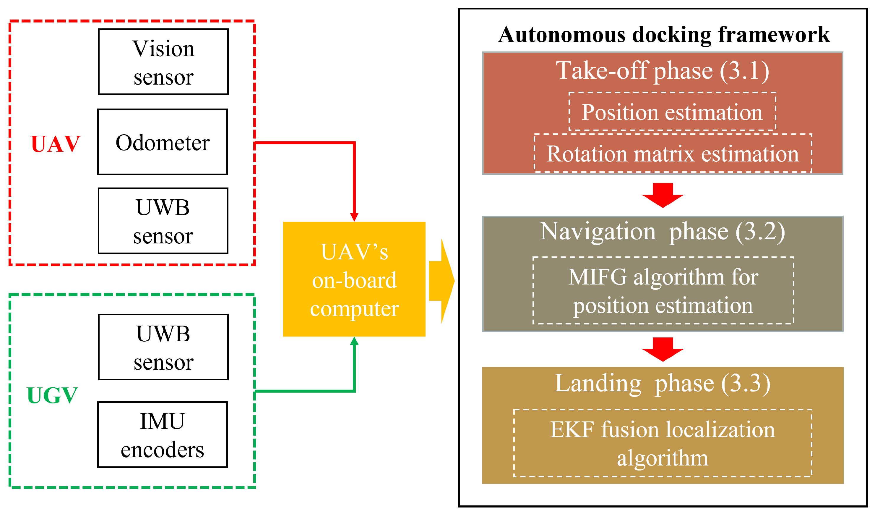
Figure 4 shows the framework of the entire autonomous docking. In this framework, UAVs and UGVs perform measurements through their own sensors, and all measured data are processed by the UAV’s on-board computer. The autonomous docking framework includes the take-off, navigation and landing phases, and the specific implementation process will be presented in Section 3.1, Section 3.2 and Section 3.3.

3.1. Take-Off Positioning Phase

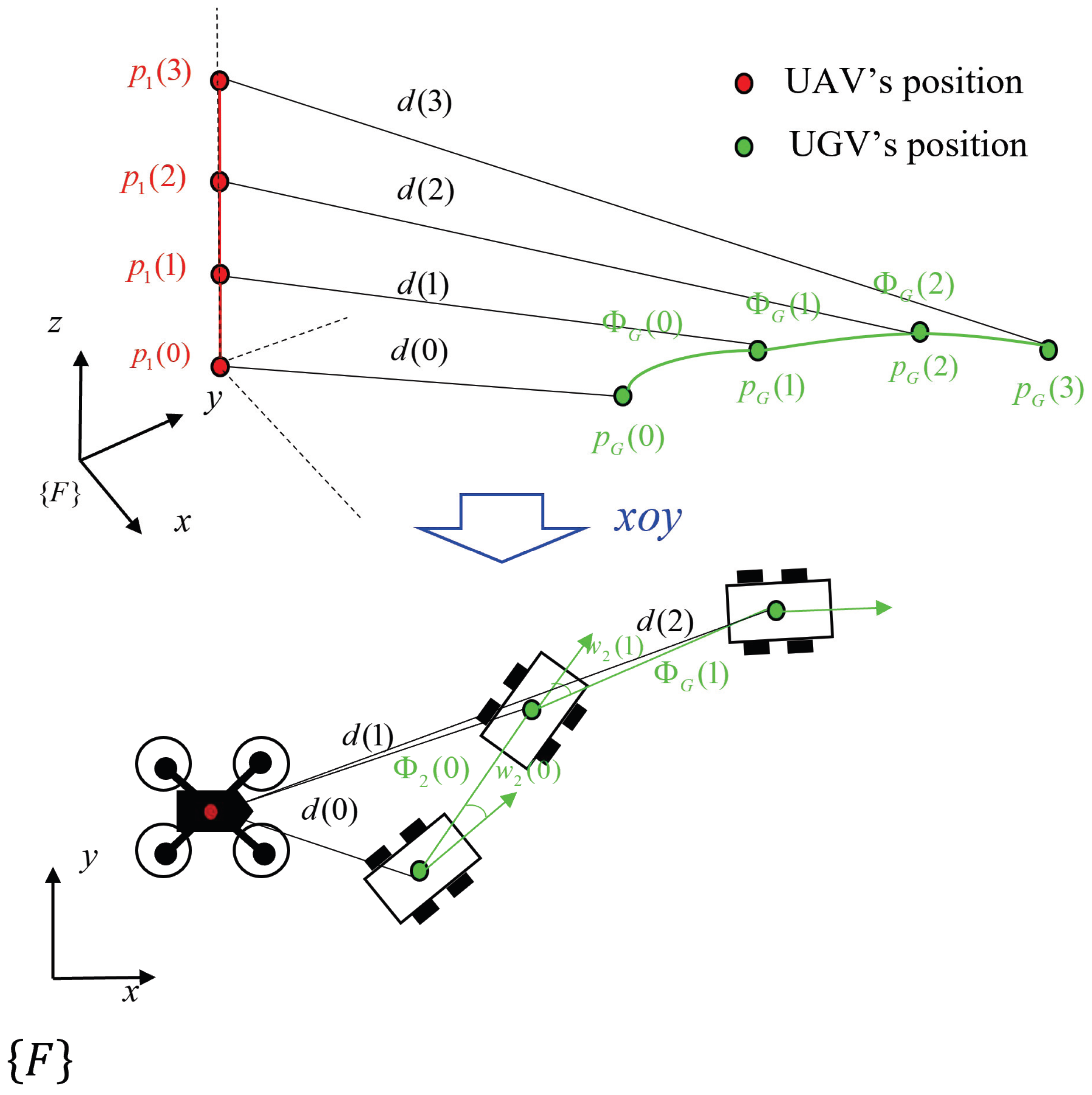
According to the framework designed in the previous section, the required relative position, q ( k 1 ) , and conversion matrix, R G F , of { G } relative to { F } are obtained through the measured data of UAV in the take-off phase. As shown in Figure 5, when the UAV takes off vertically at a constant speed, its VIO obtains altitude, UGV displacement (determined by the UGV speed and yaw angle) and their distance information { d ( 0 ) , , d ( 3 ) } through UWB. By projecting the spatial relationships onto the x o y -plane, we establish the Cayley–Menger determinant [34] relationship at time instants 0 and 1 as follows:
D p 1 ( 0 ) , p 2 ( 0 ) , p 2 ( 1 ) = 0 , D p 1 ( 1 ) , p 2 ( 2 ) , p 2 ( 2 ) = 0 .
Hence, we can determine the angles, p 1 p 2 ( 0 ) p 2 ( 1 ) and p 1 p 2 ( 1 ) p 2 ( 2 ) , that describe the geometric relationship between the two. Moreover, considering the deviation in the angles between them at this instant, we installed a UWB sensor in the forward direction of the UAV and another UWB sensor at the front of the UGV. Utilizing the relationship between their signal strengths, we can derive the actual relative position between the UAV and UGV.
Remark 3.
In projection, the height sensor is used to calculate D ( k ) = d 2 ( k ) z 1 2 ( k ) , where z 1 ( k ) is the z axis coordinate of the UAV. In summary, the relative position relationship and transformation matrix in the { F } coordinate system are mainly solved using the above geometric methods. After obtaining the relative position, based on previous work [35], the angle between the forward directions of the two UWB sensors can be calculated using UWB signal strength, thereby determining the transformation matrix, R G F , and the relative position coordinates in { A } .

3.2. Navigation Control Algorithm

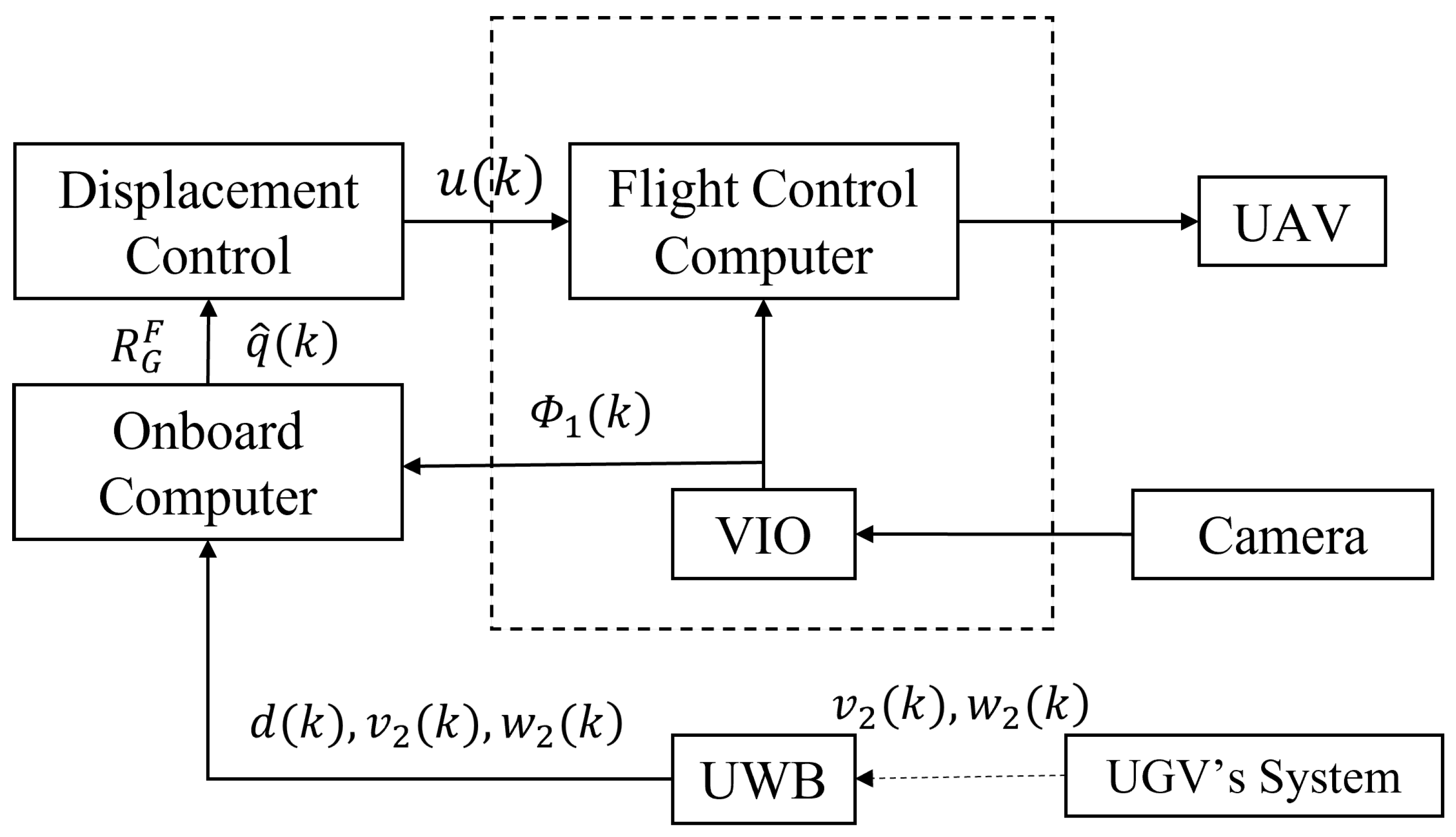
In this section, we will directly refer to Figure 6 to describe the main idea of completing the navigation task. With the preparation for navigation in the take-off stage and considering the position information, an inverse proportional saturation controller is designed as follows:
u ( k ) : = v 1 ( k ) ω 1 ( k ) = v 1 m a x R F A max v 1 m a x , q ^ ( k ) Φ 2 ( k ) q ^ ( k ) Φ 2 ( k ) 0
where q ^ ( k ) denotes the estimate of q ( k ) to be introduced later; Φ 2 ( k ) : = T R G F v 2 ( k ) ; R F A is the rotation matrix from { F } to { A } ; the yaw angle, w A ( k ) , is not considered at this stage for the time being; and max { A , B } represents the larger value between A and B. Note that the controller, at this time, mainly controls the quantities in the x o y -plane, and the height control is zero. Finally, the obtained control signal, u ( k ) , is transmitted to the UAV through the flight control computer, enabling the control of the UAV in the body coordinate system.
As shown in Figure 2, by using the displacement relationship between UAVs and unmanned ground vehicles in space, the following results can be obtained:
[ d ( k ) e ( k ) ] 2 = q ( k 1 ) + T R A F v 1 ( k ) T R G F v 2 ( k ) q ( k 1 ) + T R A F v 1 ( k ) T R G F v 2 ( k ) ,
[ d ( k 1 ) e ( k 1 ) ] 2 = q ( k 1 ) q ( k 1 ) ,
where e ( k ) is the measurement noise of UWB, which is a random noise sequence that satisfies the following assumptions.
Assumption 3.
There exists a constant, σ e > 0 , such that the measurement noise, e ( k ) , satisfies the following:
E [ e ( k ) ] = 0 ; E [ e ( k ) e ( j ) ] = 0 , f o r k j ; E e 2 ( k ) σ e 2 < ; e ( k ) [ 0.1 , 0.1 ] .
Remark 4.
e ( k ) is the error generated by the UWB sensor through measurements that are within 10 cm and independently uncorrelated for each moment.
The following equation can be obtained using Equations (13) and (14):
d 2 ( k ) d 2 ( k 1 ) + 2 d ( k ) e ( k ) 2 d ( k 1 ) e ( k 1 ) = T 2 R A F v 1 ( k ) R G F v 2 ( k ) 2 + 2 T R A F v 1 ( k ) R G F v 2 ( k ) q ( k 1 ) + e 2 ( k 1 ) e 2 ( k ) .
With the above relationship, let us define
ζ ( k ) : = 1 2 d 2 ( k ) d 2 ( k 1 ) T 2 R A F v 1 ( k ) R G F v 2 ( k ) 2 , φ ( k ) : = T R A F v 1 ( k ) R G F v 2 ( k ) , ν ( k ) : = d ( k ) e ( k ) d ( k 1 ) e ( k 1 ) + 1 2 [ e 2 ( k ) e 2 ( k 1 ) ] .
Using Equation (17), one then has the following:
ζ ( k ) = φ ( k ) q ( k 1 ) + ν ( k ) ,
which will later be employed to estimate q ( k ) .
Remark 5.
For ν ( k ) in Equation (17), through d ( k ) = q ( k ) + e ( k ) , the following can be obtained:
ν ( k ) = ( q ( k ) + e ( k ) ) e ( k ) ( q ( k 1 ) + e ( k 1 ) ) e ( k 1 ) + 3 2 [ e 2 ( k ) e 2 ( k 1 ) ] = q ( k ) e ( k ) q ( k 1 ) e ( k 1 ) + 3 2 [ e 2 ( k ) e 2 ( k 1 ) ] ,
where, by defining q ¯ : = q ( k ) + q ( k 1 ) , the term q ( k ) e ( k ) q ( k 1 ) e ( k 1 ) has a mean of 0 and takes values from the interval ( 0.1 q ¯ , 0.1 q ¯ ) . In addition, e 2 ( k ) e 2 ( k 1 ) is a random noise with a mean of zero and takes values from the interval ( 0.01 , 0.01 ) . Therefore, ν ( k ) is regarded as a noise random sequence with zero mean value and takes values from the interval ( 0.1 q ¯ 0.015 , 0.015 + 0.1 q ¯ ) .
To proceed, let us first define the following parameters:
Φ ( p , k ) = [ φ ( k ) , φ ( k 1 ) , , φ ( k p + 1 ) ] R 3 × p ,
Z ( p , k ) = [ ζ ( k ) , ζ ( k 1 ) , , ζ ( k p + 1 ) ] R p ,
r ( k ) = λ r ( k 1 ) + φ ( k ) 2 , r ( 0 ) > 0 ,
where p is the horizon of multiple innovation, 0 < λ < 1 and N is an integer.
Therefore, the cost function can be constructed through Equations (20)–(22), as follows:
J ( k ) : = E Z ( p , k ) Φ T ( p , k ) q ( k ) 2 ,
where the above formula is the expectation of a square error. Then, by minimizing the cost function, the approximation algorithm is proposed as follows:
q ^ ( k ) = q ^ ( k 1 ) + Φ ( p , k ) r ( k ) E ( p , k ) ,
E ( p , k ) = Z ( p , k ) Φ T ( p , k ) q ^ ( k 1 ) ,
where E ( p , k ) R p is an innovation vector, namely, multi-innovation. Equations (20)–(22), (24) and (25) are called the MIFG algorithm.
Lemma 1.
For Equation (22), if the information vector, φ ( k ) , in Equation (17) is persistently excited, that is, there exists α > 0 and β > 0 and an integer, N 3 , such that the following holds:
α I 1 N i = 0 N 1 φ ( k + i ) φ T ( k + i ) β I , a . s . , k > 0 ,
and φ ( k ) 2 α , and if α 1 λ r ( 0 ) 3 N β 1 λ , then r ( k ) satisfies the following:
α 1 λ r ( k ) 3 N β 1 λ .
The proof of Lemma 1 is given in Appendix A.
Remark 6.
Compared with the simple use of two groups of data, such as estimating the relative position, q ^ ( k 1 ) , increasing the innovation horizon, p, will lead to a smaller relative position estimation error. However, a larger p will inevitably incur a heavier computational power, which should be a tradeoff in practical implementations.
Assumption 4.
The relative position changing rate, ω ( k ) : = q ( k ) q ( k 1 ) , of the UAV and UGV, is uncorrelated with ω ( j ) for k j . At the same time, the changing rate should be square-bounded, i.e., E ω ( k ) = 0 and E ω ( k ) 2 σ ω 2 < , for some σ ω > 0 . In addition, it is assumed that e ( k ) and w ( k ) are independent, i.e., E e ( k ) w ( k ) = 0 .
With the above preparation, it is now possible to present the first main result of this study, which is the convergence of the proposed multi-innovation forgetting gradient (MIFG) algorithm.
Theorem 1.
For Equations (24) and (25), let Assumptions 1, 3 and 4 hold, and the innovation horizon p = N . Then, the estimation error given by the MIFG algorithm satisfies the following:
E q ^ ( k ) q ( k ) 2 [ 1 α ( 1 λ ) β ] k q ^ ( 0 ) q ( 0 ) 2 + 9 ( 1 1 α ( 1 λ ) β ) 2 × 3 N 4 β 2 ( 1 λ ) 2 σ ω 2 2 α 2 + N 2 β ( 1 λ ) 2 σ ν 2 α 2 + σ ω 2 .
The proof of Theorem 1 is given in Appendix A.
Remark 7.
The physical meaning of Theorem 1 is that the error between the estimated relative position, q ^ ( k ) , obtained by MIFG and the true relative position, q ( k ) , is bounded.
Remark 8.
Compared with the literature relying on GPS information [9,36,37] or MCS [38,39,40] for positioning, the method in this study uses only a range sensor and its odometer to achieve navigation and positioning at a minimum deployment cost. Compared with relative positioning based on visual search, the method here has wider-range measurements, shorter searching times and requires fewer computing resources. Compared with [29,30], this study considers a dynamic random target. Compared with [28], we consider the measurement error and use historical data for estimation in control.

3.3. Multi-Sensor Fusion Landing Scheme

This subsection focuses on the case where the UGV appears in the FOV of the camera. The pose of the target is obtained by fusing multiple sensors, and the landing is completed by designing a controller.
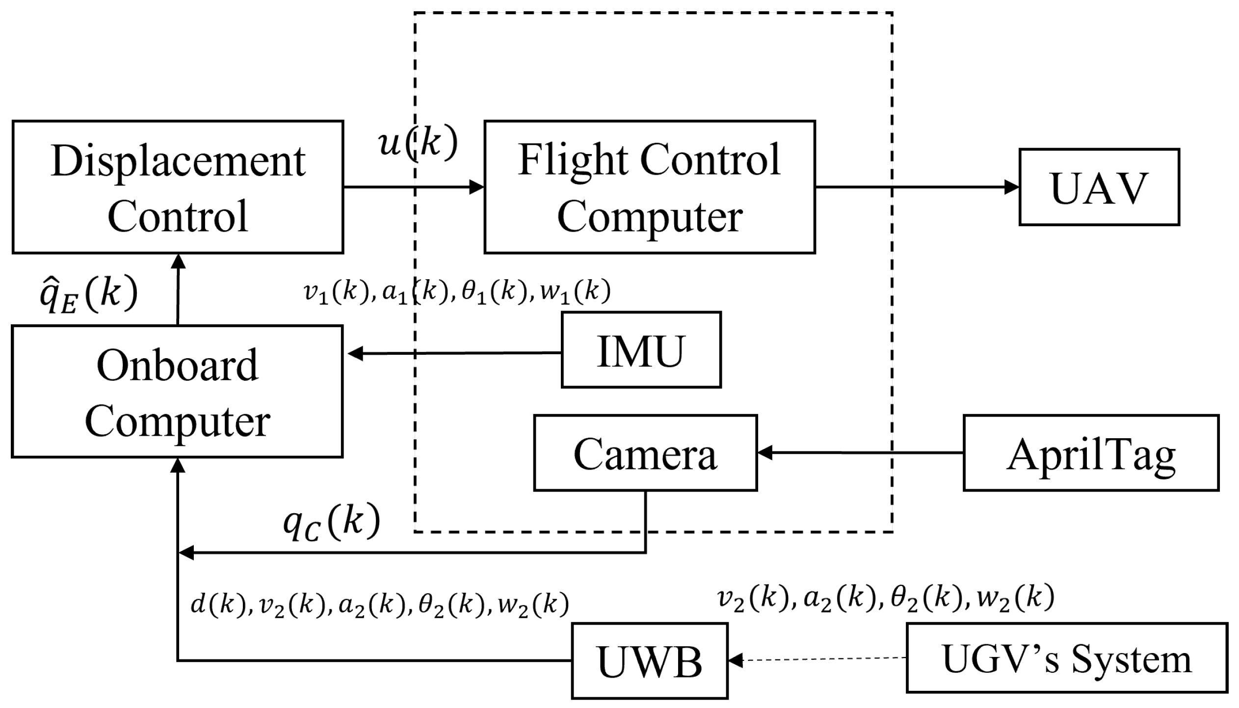
As shown in Figure 7, the overall idea is to fuse the Vision-UWB-IMU data based on the EKF to obtain the relative position coordinates between the UAV and UGV for landing control.
Assumption 5.
In the landing phase, it is assumed that a change in vehicle speed can be ignored. In addition, the distance measured by UWB is the same as the distance measured by vision, that is, the position of the tag and UWB node are regarded as the same position on the UGV.
To proceed, define the following:
x : = q , ψ q ,
where q ( k ) = [ q x ( k ) , q y ( k ) , q z ( k ) ] represents the relative position of the UAV to the landing site and ψ q ( k ) indicates the relative heading angle of the UAV to the landing point. Moreover, the dynamics of x in { A } can be compactly written as follows: x ˙ = f ( x , u , ξ ) , where f denotes the evolution function of x and ξ represents the system noise.
For a precise landing, the landing point is selected differently from the UWB location. According to Figure 3, the relative position estimated by the UWB sensor at this moment is as follows:
q U ( k ) = q ^ ( k ) + A U C .
The next step is to use the EKF method to fuse the on-board IMU/encoder, vision sensor and UWB data to obtain the following:
x ^ k + = ( q ^ x + ( k ) , q ^ y + ( k ) , q ^ z + ( k ) , ψ ^ + ( k ) ) ,
where q ^ x + ( k ) , q ^ y + ( k ) and q ^ z + ( k ) are position components of the estimated relative position and ψ ^ + ( k ) represents the estimated relative yaw angle. In particular, the camera sensor will obtain the relative position and yaw angle between the UAV and AprilTag; the UWB continues to be used to estimate relative positions, as performed previously; and the IMU/encoder can obtain the relative velocity, position and angle between the UAV and UGV.
Remark 9.
The EKF method has been widely used for different sensors in engineering applications and has been verified to be a better method in practice, so this study does not introduce the algorithm in detail [41,42]. Note that data are obtained from both the UAV’s IMU and UGV’s IMU/encoder, which are not presented in this study and can be found in [41].
After obtaining the relative position, x ^ k + , of multi-sensor fusion, the controller is designed to track the position in x and y directions and compensate the UGV’s velocity as follows:
u ( k ) = q ^ x + ( k ) / T q ^ y + ( k ) / T z ¯ A ( k ) / T ψ ^ + ( k ) / T + R G A v 2 ( k ) 0 .
where R G A is the transformation matrix from { G } into { A } . Note that, unlike the navigation phase, the UAV controller is designed based on position control and
z ¯ A ( k ) : = a z , | q ^ x + ( k ) | 2 + | q ^ y + ( k ) | 2 0.1 0 , | q ^ x + ( k ) | 2 + | q ^ y + ( k ) | 2 > 0.1 ,
where a z is a prespecified falling average height. Then, finally, when the estimated relative height, q ^ z + , reaches a certain threshold value, i.e., satisfies the landing altitude, the UAV power is cut off to complete the landing.
Remark 10.
The main contribution of this subsection is that compared with the method of relative positioning using only vision [13,17,43], the data fusion estimation of relative positioning combined with UWB, IMU, and the encoder is carried out, and the higher positioning accuracy is demonstrated using a numerical simulation. Moreover, an unmanned landing controller based on spatial location information is designed.

4. Experiments

This section presents the simulation and experimental results of autonomous docking.

4.1. Simulation

The simulation experiment includes the following: dynamic models of the UAV and UGV, three-stage control algorithms, odometer noise, measurement noise and so on.
The simulation environment is set to be level ground without obstacles, the sampling period is 0.1 s, the UAV initial test coordinates are ( 0 , 0 , 0 ) and the UGV initial test coordinates are ( 30 , 25 , 0.2 ) , where 0.2 is the UGV platform height. The maximum speed of the UAV is 5 m/s. It is designed as a four-rotor unmanned aircraft, so the yaw angle is omni-directional. The maximum sailing speed and initial yaw angle of the UGV are 2 m/s and π / 8 , the acceleration changes randomly within ( 0.1 , 0.1 ) m / s and the yaw angular acceleration changes randomly within ( 6 / π , 6 / π ) , with a period of 1 s.
In terms of noise, the measurement noise of UWB is a stochastic noise sequence that follows a uniform distribution with a mean value of zero in the range of ( 0.1 m , 0.1 m ) . Random noise that follows a uniform distribution with a mean value of zero ( 0.1 m / s , + 0.1 m / s ) is added to the UAV odometer, and speed noise that follows U ( 0.01 m / s , + 0.01 m / s ) is added to the vehicle axle. In the landing phase, considering the fusion algorithm under the EKF framework, the system (6) noises satisfy N 0 , 0 . 1 2 , UWB’s observation noises satisfy N 0 , 0 . 1 2 and the three dimensions of the camera’s measurement are added, with random noises following N 0 , 0 . 05 2 .
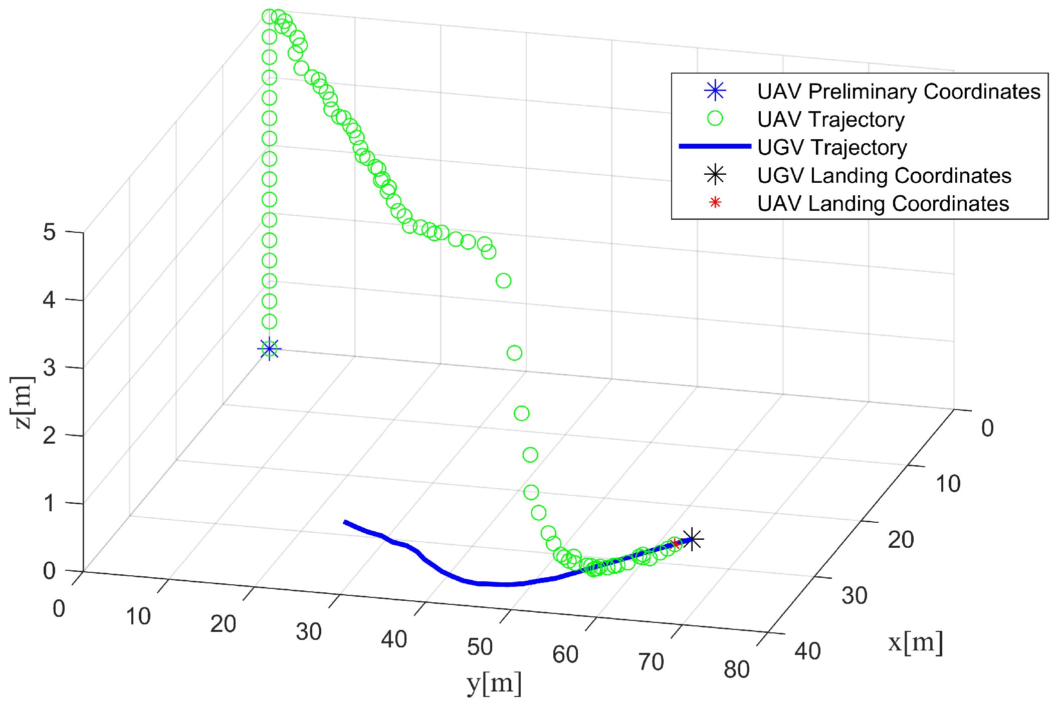
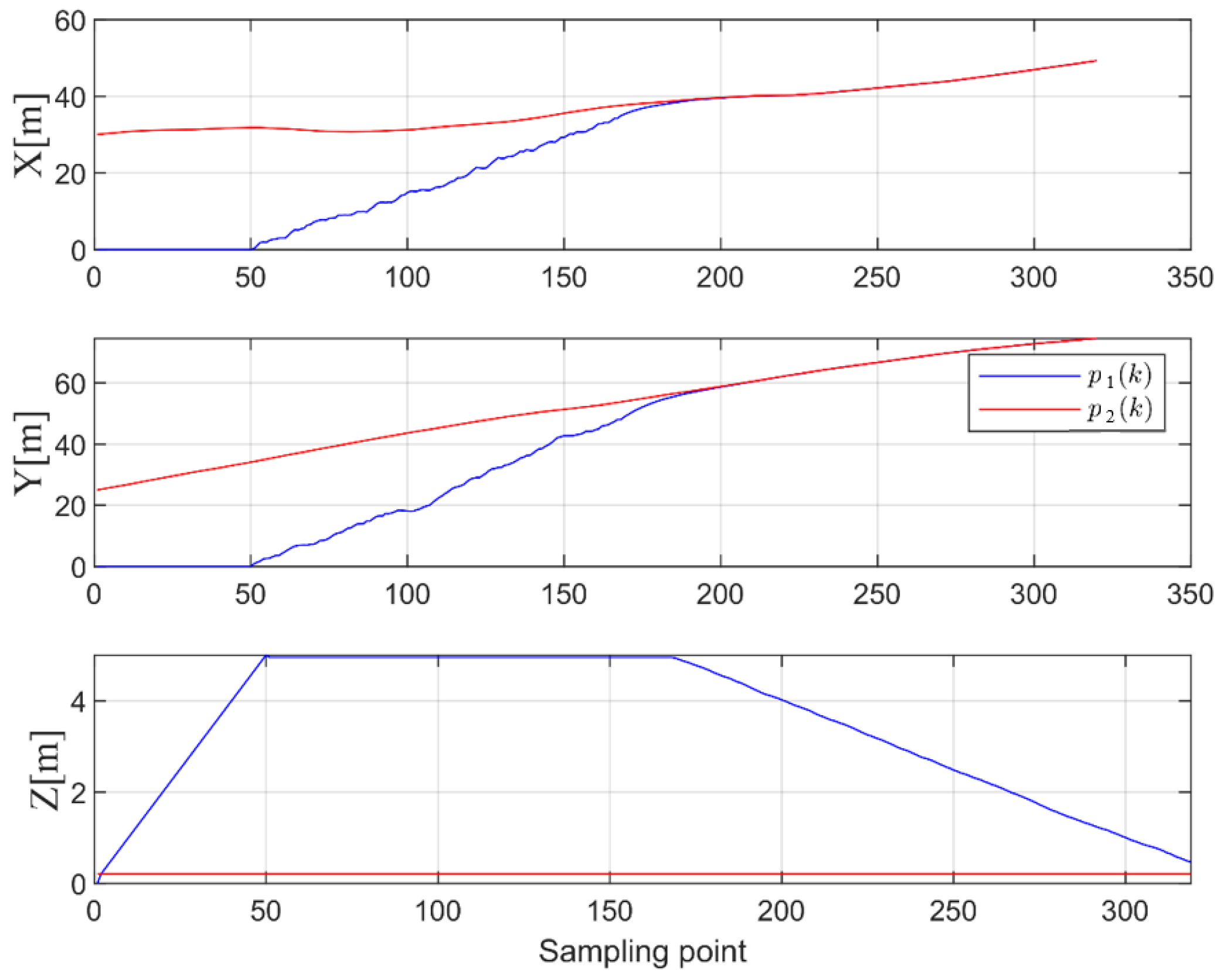
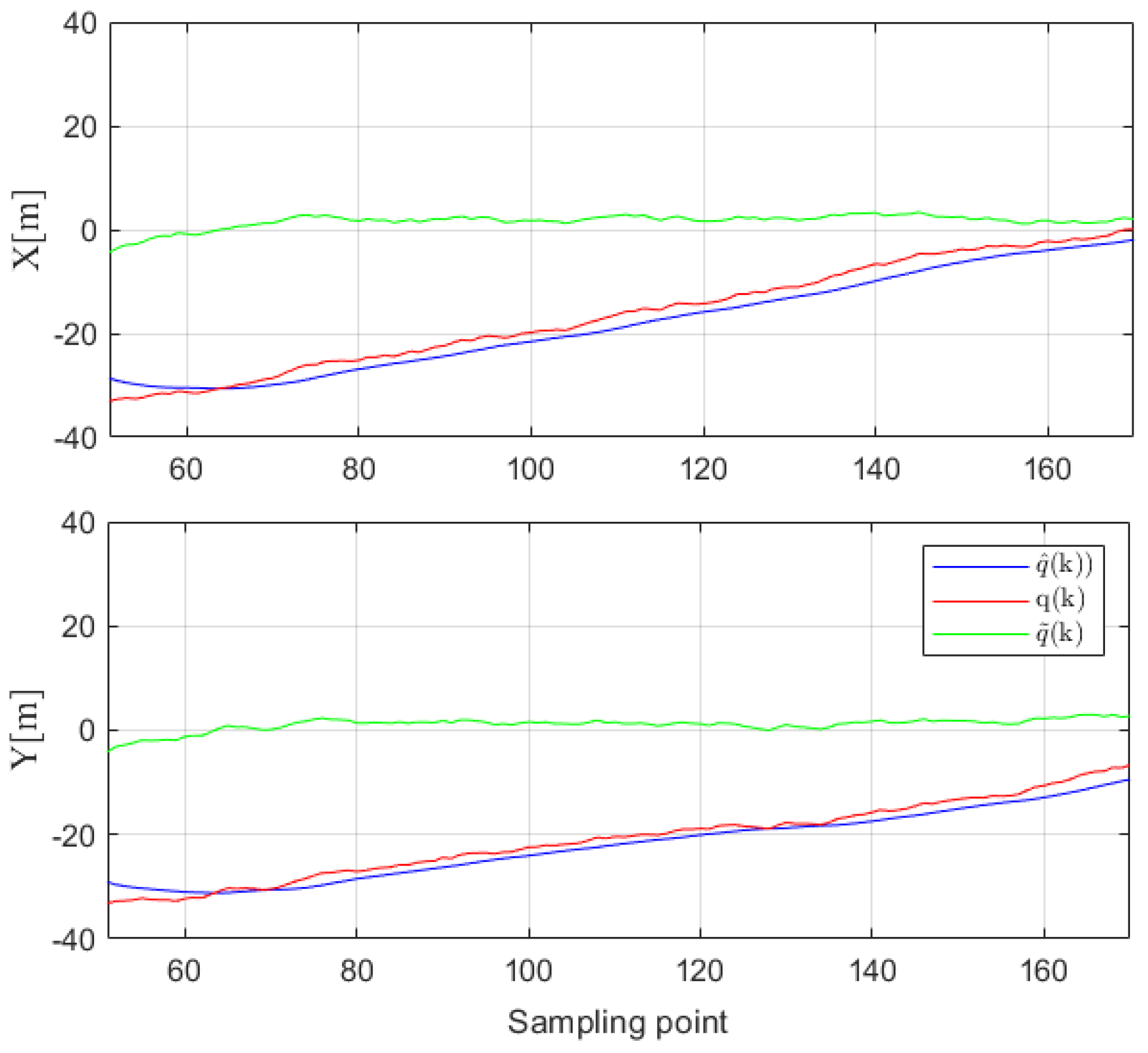
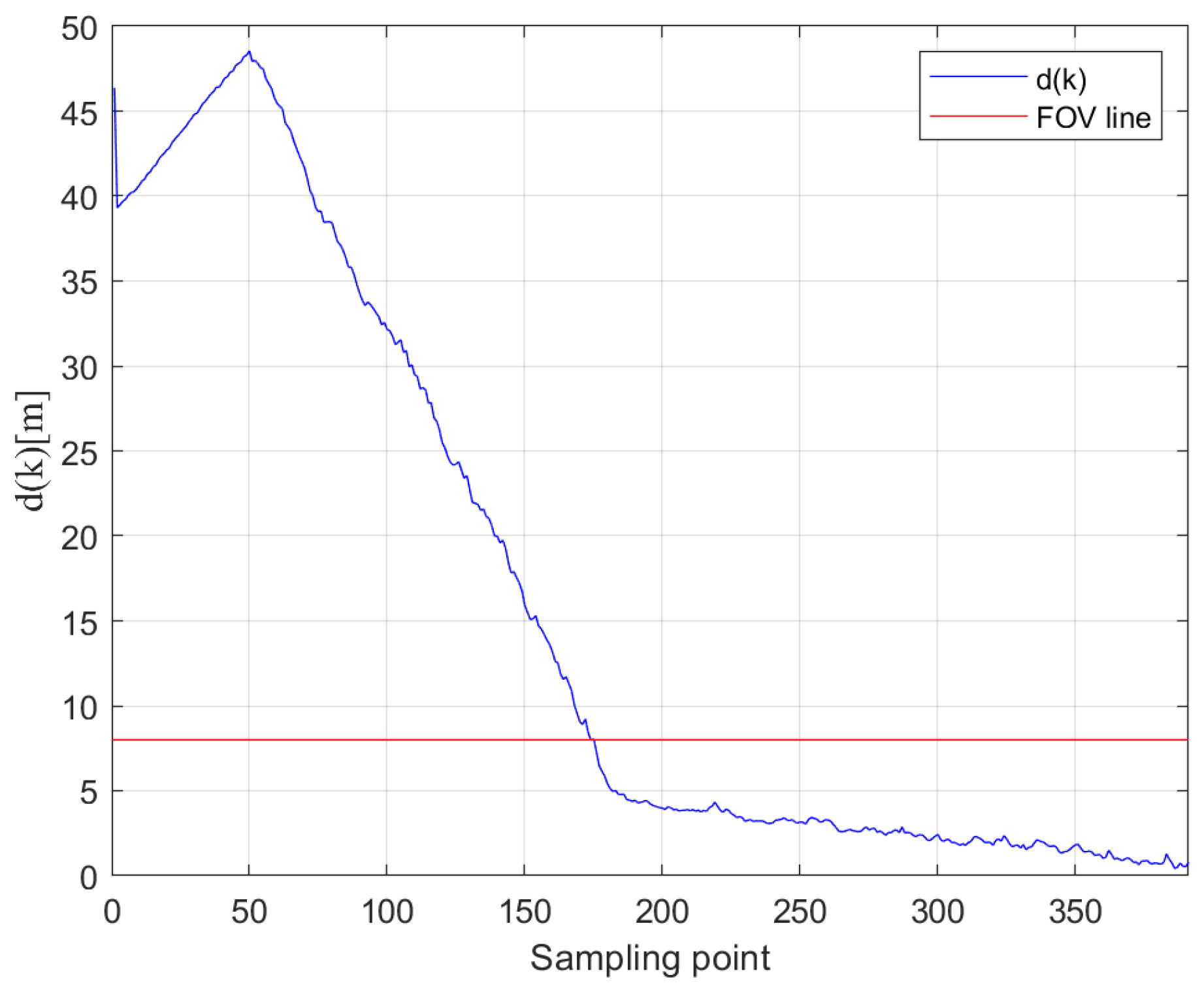
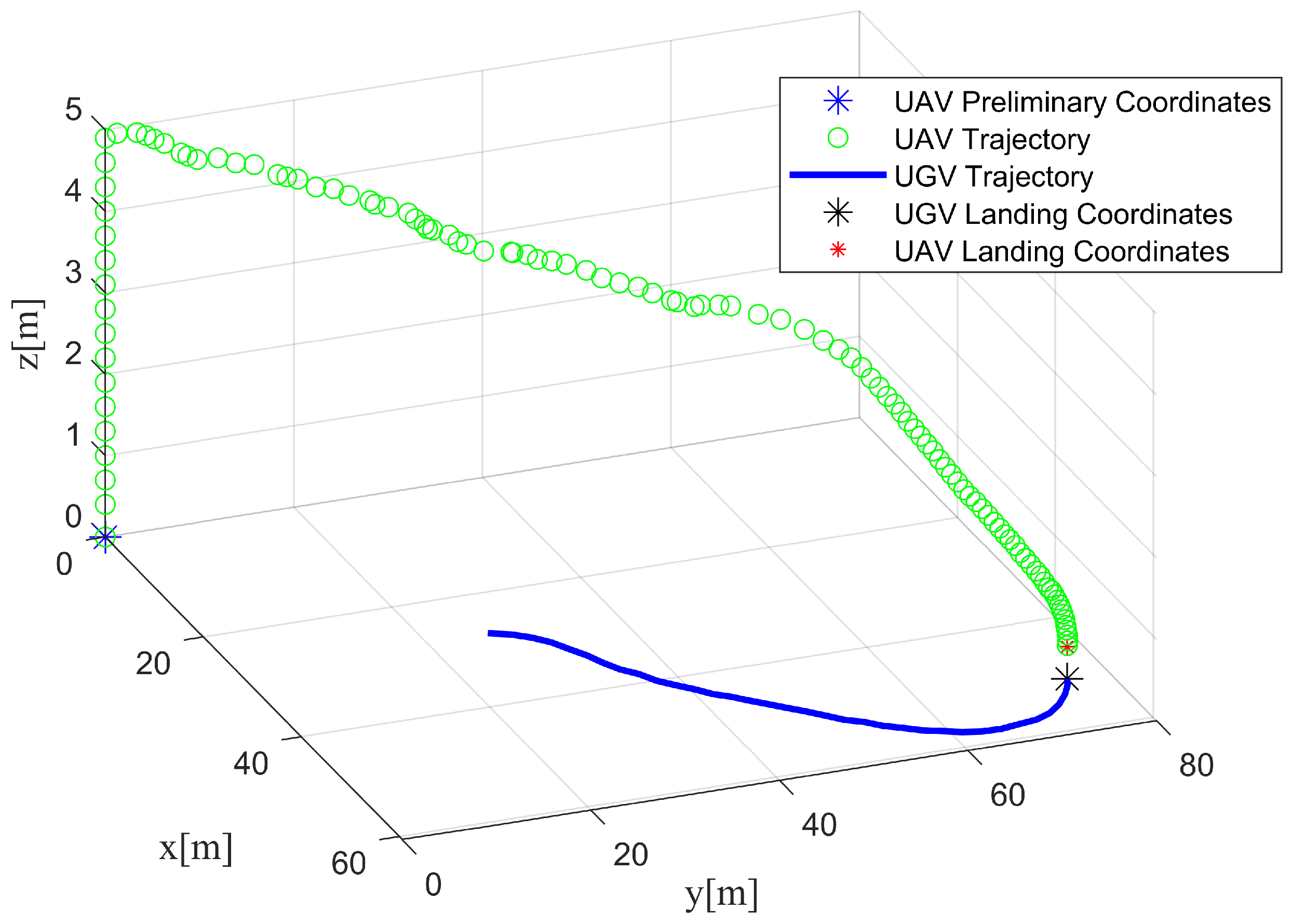
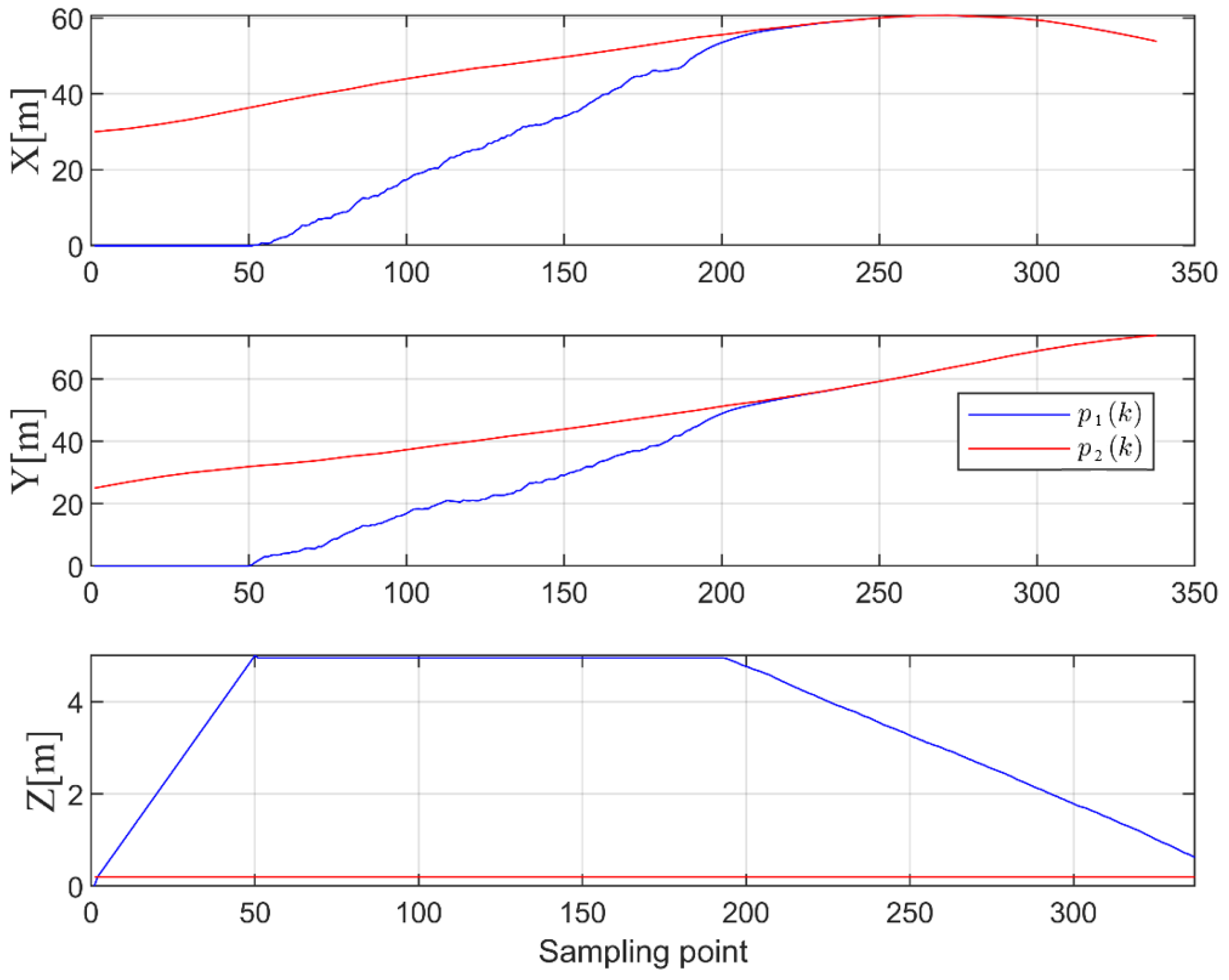
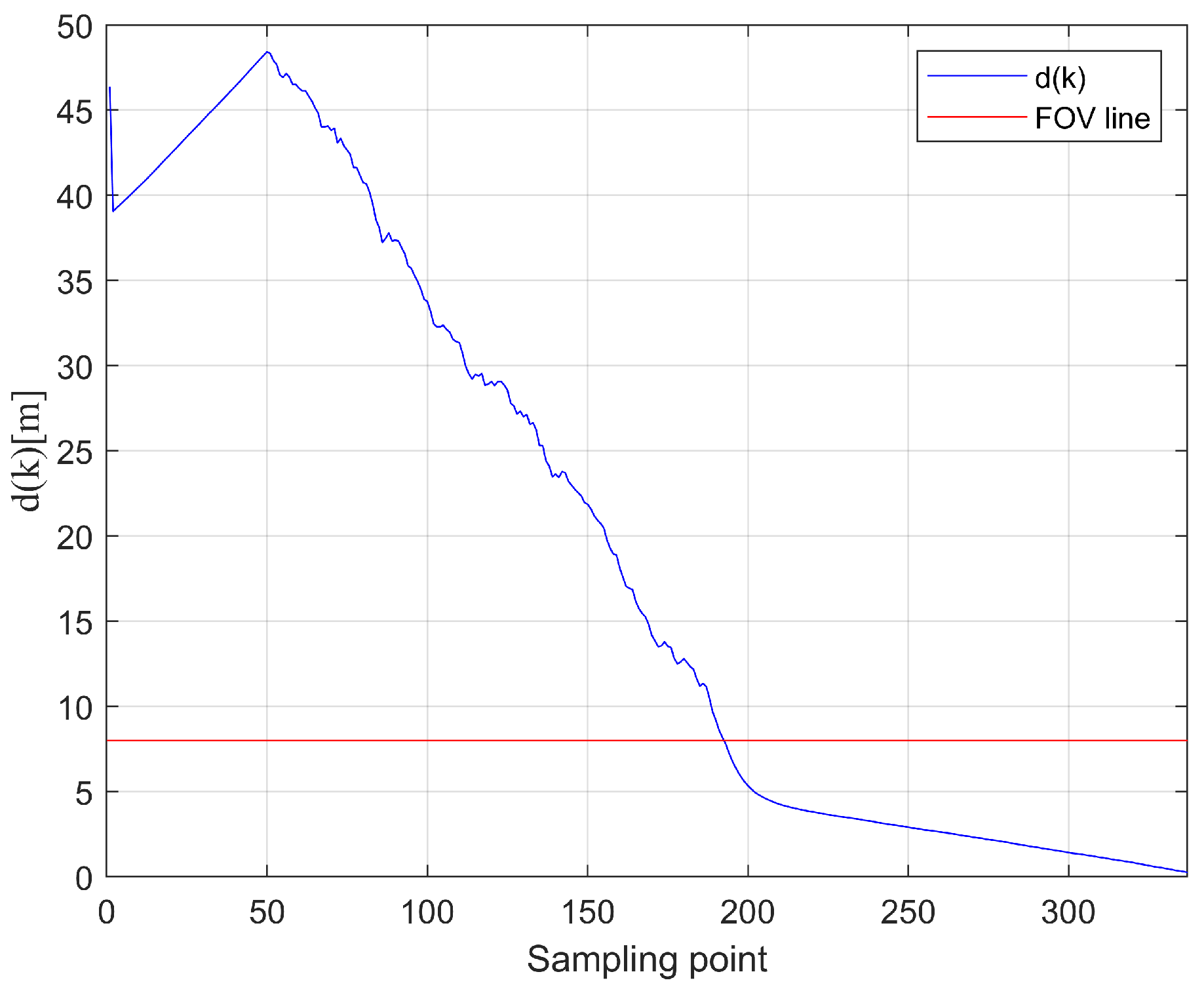
In terms of parameters, let p = 3 , λ = 0.9 , l = 0.5 and r ( 0 ) = 0.30 . The simulation results are shown in Figure 8, Figure 9, Figure 10 and Figure 11.
From Figure 8, the whole trajectory process of the UAV from take-off to landing on the UGV can be observed. The UAV takes off and climbs at a constant speed of 1 m / s to a height of 5 m . During this period, the relative position and conversion matrix of the preliminary test are solved through distance measurements and UGV speed information. In the navigation phase, the relative position, q ^ , is estimated by the MIFG algorithm based on displacement, distance, UGV speed and historical data, and the UAV is navigated according to the designed control algorithm until the UGV appears in the FOV of the camera. Finally, the landing is carried out. EKF fusion is carried out using the relative position obtained by the vision and the distance information measured by UWB, and the speed of the UGV is compensated for. Through image analysis, it can be concluded that the fused data are closer to the real data. Finally, the landing is completed.
Subsequently, the position estimation error, q ˜ : = q ^ q , is defined, and the root mean square (RMS) and standard deviation (SD) of the positioning error are made for the navigation and landing phases, respectively. In order to compare the superiority of MIFG, we perform a comparison with the forgetting factor least squares method [30] ((FFLS) where the forgetting factor is taken as 0.9 ) in the navigation phase, as shown in Table 1 and Table 2. Through the analysis of RMS and SD, it can be seen that, during the navigation phase, both algorithms can estimate relative position data that meet the task of imprecise navigation. However, when the parameters, noises and models are the same, MIFG utilizes more historical information and is more accurate than FFLS, which only utilizes the measurement data at two specific times. In the landing phase, the fused relative position data have high accuracy, which is enough for precise landing.
In order to further explore the anti-interference performance of the algorithm, the measurement noise of UWB is a stochastic noise sequence following a uniform distribution with a mean value of zero and values in the range of ( 0.2 m , 0.2 m ) , while other noise is also increased by twice as much as before. The simulation results are shown in Figure 12, Figure 13, Figure 14 and Figure 15 and Table 3 and Table 4. From the simulation results, it can be seen that, although noise increases and accuracy may be affected, the docking task can still be successfully completed. In the navigation phase, MIFG performs better than FFLS, and its accuracy meets the needs of navigation. In the landing phase, the positioning accuracy of fusion is still more accurate than solely using UWB or vision.
In summary, the above simulation experiments have verified the accuracy and robustness of the proposed MIFG navigation and fusion landing algorithms.

4.2. Real Experiment

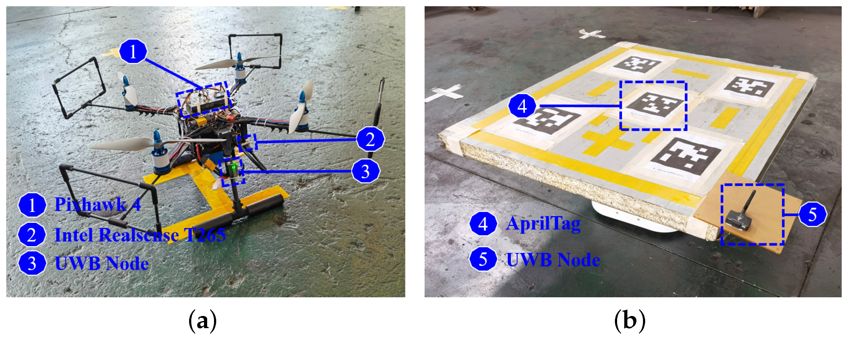
As shown in Figure 16, our experiment is based on a 9-inch paddle quadcopter equipped with a Pixhawk 4 (http://px4.io, accessed on 21 September 2023) flight controller, which also provides IMU measurements. An Intel RealSense T265 camera (https://www.intelrealsense.com/, accessed on 21 September 2023) is installed under the UAV to provide image information, which is processed by an Intel NUC Core i7 mini computer. Displacement measurements are calculated using VIO (https://docs.px4.io/master/en/peripherals/camera_t265_vio.html, accessed on 21 September 2023). The mini computer’s operating system is Ubuntu 18.04 with ROS Melodic (https://wiki.ros.org/melodic, accessed on 21 September 2023) installed. The on-board computer acts as the upper monitor and communicates with the flight control through MAVROS (https://wiki.ros.org/mavros, accessed on 21 September 2023).
Distance measurements are obtained using two UWB nodes, which can provide accurate values with an error within a 10 cm range (DWM1000 module (https://www.decawave.com/product/dwm1000-module, accessed on 21 September 2023)). The UGV is a two-wheeled mobile system robot ( l = 0.35 m ) with an encoder, which is equipped with a 1.5 m × 1 m × 0.5 m landing platform. The platform is installed with a UWB anchor point and AprilTag (https://github.com/AprilRobotics/apriltag, accessed on 21 September 2023) identification.
In the overall experiment, the UAV is fully automatic (the input speed is controlled and converted into displacement through a flight controller to control the UAV), the UGV is randomly controlled by a human, with no human-made plan on the UGV’s trajectory, and the encoder carried by the UGV detects the speed and heading angle. The video results of the experiment can be found at https://youtu.be/0AvEY_DkCkE, accessed on 21 September 2023.
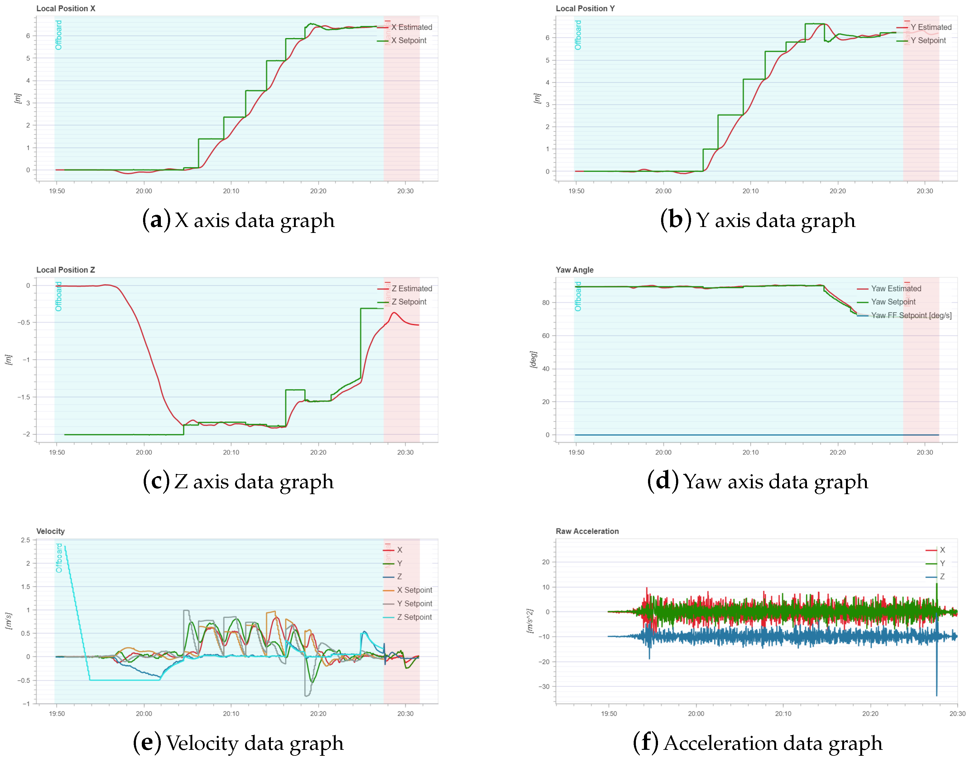
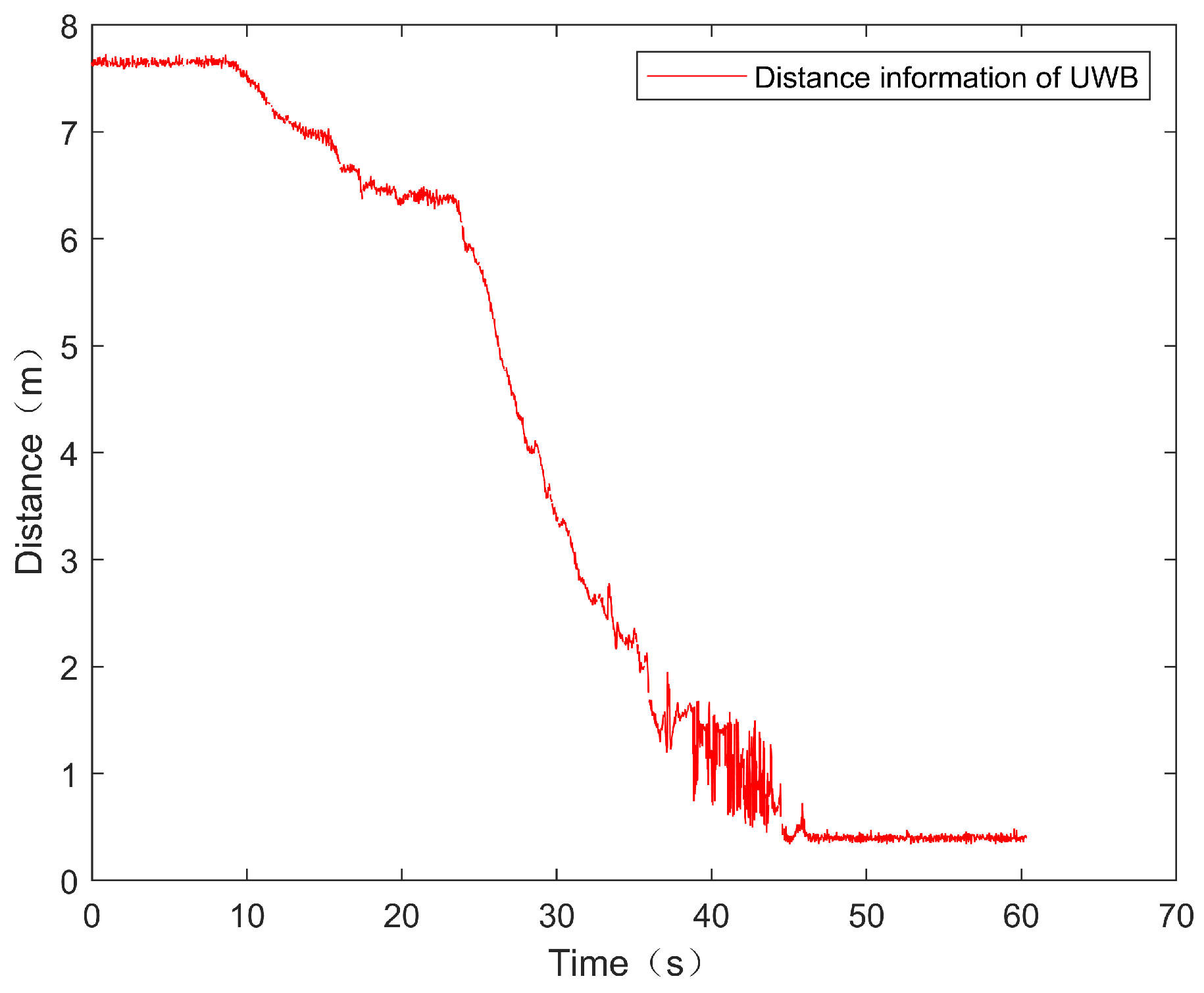
Figure 17 shows the results of the whole docking experiment. The docking results for the UAV vision inspection are shown in Figure 18; we required that the distance between the center of the UGV and UAV should be less than 5 cm when the landing was completed. The images show that the UAV can be guided by the approaching algorithm proposed in this study to fly above the UGV, and in the landing phase, the UAV can land precisely on the moving UGV using the proposed controller. Figure 19 shows the flight log saved by Pixhawk 4, which is displayed through Flight Review (https://logs.px4.io/, accessed on 21 September 2023). Figure 20 shows the distance information measured by UWB, indicating that the UAV gradually approaches the UGV and, finally, completes the landing. The whole experimental flight distance was about 14.5 m and lasted approximately 40 s .

5. Conclusions

In this study, a UAV/UGV autonomous navigation docking scheme was proposed by combining UWB with vision in GPS-denied environments. The relative position was estimated through distance, displacement, and historical information, and an MIFG control algorithm was designed. During the landing process, a landing controller was proposed based on a multi-sensor EKF fusion framework, which can effectively complete the docking. Finally, the effectiveness of the autonomous navigation scheme was verified and validated using a numerical simulation and a real experiment. The main contribution of this study is solving autonomous docking problems in GPS-denied environments, where the UGV is a random non-cooperative target. However, due to the inherent performance of UWB, the method may not be ideal beyond the measurement range ( 500 m ). Moreover, pitch and roll will be further considered for uneven grounds in the future. Another future work is to consider autonomous docking for multiple drones and UGVs.

Author Contributions

This research was accomplished by all the authors. C.C., X.L., L.X. and L.L. conceived the idea, performed the analysis and designed the scheme; C.C. and L.X. conducted the numerical simulations; C.C. and L.X. conducted real experiments; C.C., X.L. and L.X. co-wrote the manuscript. All authors have read and agreed to the published version of the manuscript.

Funding

This work was supported by the National Natural Science Foundation of China (grant: 62003243), the Fundamental Research Funds for the Central Universities (No.: 22120210099), the Shanghai Municipal Commission of Science and Technology (No.: 19511132101), the Shanghai Municipal Science and Technology Major Project (grant: 2021SHZDZX0100), the Shanghai Gaofeng & Gaoyuan Project for University Academic Program Development (No.: 22-3) and the Basic Science Centre Program by the National Natural Science Foundation of China (grant: 62088101).

Institutional Review Board Statement

Not applicable.

Informed Consent Statement

Not applicable.

Data Availability Statement

Not applicable.

Conflicts of Interest

The authors declare no conflict of interest.

Appendix A

Appendix A.1. Lemma 1

Proof of Lemma 1.
By taking the trace of condition Equation (26), it is easy to obtain the following:
n N α i = 0 N 1 φ ( k + i ) 2 n N β , a . s . ,
where n = 3 is the dimension of the vector, φ ( k ) .
From Equation (22), one can obtain the following:
r ( k ) = λ r ( k 1 ) + φ ( k ) 2 = i = 1 k λ k i φ ( i ) 2 + λ k r ( 0 ) i = 1 k λ k i j = 0 N 1 φ T ( i + j ) φ ( i + j ) + λ j r ( 0 ) i = 1 k λ k i [ 3 N β ] + λ k r ( 0 ) = 3 N β 1 λ + r ( 0 ) 3 N β 1 λ λ k 3 N β 1 λ , a . s . , r ( k ) i = 1 k λ k i α + λ k r ( 0 ) = α 1 λ k 1 λ + λ k r ( 0 ) = α 1 λ + λ k r ( 0 ) α 1 λ α 1 λ , a . s . ,
where the first line uses the assumption φ ( k ) 2 α .
This completes the proof of Lemma 1. □

Appendix A.2. Theorem 1

Proof of Theorem 1.
Define the parameter estimation error as
q ˜ ( k ) : = q ^ ( k ) q ( k ) ,
and define the noise, V ( p , k ) , and auxiliary, Ω ( k ) , vectors as follows:
Ω ( k ) : = 0 φ ( k 1 ) ω ( k 1 ) φ ( k 2 ) ω ( k 1 ) + ω ( k 2 ) φ ( k p + 1 ) j = 1 p 1 ω ( k j ) R p ,
V ( p , k ) : = ν ( k ) ν ( k 1 ) ν ( k p + 1 ) R p .
Expand Equation (24) with Equation (A2) as follows:
q ˜ ( k ) = q ^ ( k ) q ( k ) = q ^ ( k 1 ) + Φ ( p , k ) r ( k ) E ( p , k ) q ( k 1 ) + ω ( k ) = q ˜ ( k 1 ) + Φ ( p , k ) r ( k ) Z ( p , k ) Φ T ( p , k ) q ^ ( k 1 ) ω ( k ) = q ˜ ( k 1 ) + Φ ( p , k ) r ( k ) [ Φ T ( p , k ) q ˜ ( k 1 ) Ω ( k ) + V ( p , k ) ] ω ( k ) = [ I Φ ( p , k ) r ( k ) Φ T ( p , k ) ] q ˜ ( k 1 ) Φ ( p , k ) r ( k ) [ Ω ( k ) V ( p , k ) ] ω ( k ) ,
where the second line uses Equation (24) and Assumption 4 ( ω ( k ) ); the third line uses Equations (25) and (A2); and the fourth line uses Equations (21) and (A3) as well as Assumption 4 ( ω ( k ) ).
By using Assumptions 3 and 4, it is easy to verify that ν ( k ) satisfies E [ ν ( k ) ] = 0 , E ν ( k ) w ( k ) = 0 and E ν 2 ( k ) σ ν 2 < for some σ ν > 0 . By further using Assumptions 1–2, noting p = N and n = 3 , one has the following:
E [ Φ ( p , k ) V ( p , k ) 2 ] E { Φ ( p , k ) 2 V ( p , k ) 2 } = E { ( i = 1 p φ ( k i + 1 ) 2 ) V ( p , k ) 2 } 3 p β E [ V ( p , k ) 2 ] = 3 N β E [ i = 1 p ν 2 ( k i + 1 ) ] 3 N 2 β σ ν 2 ,
where the first step uses the inequality a 1 + + a n 2 n ( a 1 2 + + a n ) 2 ; the second step uses Equation (20); the third step cf. Equation (A1); the fourth step uses Equation (A4); and the fifth step uses E ν 2 ( k ) σ ν 2 < .
E [ Φ ( p , k ) Ω ( p , k ) 2 ] 3 N β E Ω ( p , k ) 2 = 3 N β E { φ T ( k 1 ) w ( k 1 ) 2 + φ T ( k 2 ) [ w ( k 1 ) + w ( k 2 ) ] 2 + + φ T ( k p + 1 ) s [ w ( k 1 ) + w ( k 2 ) + + w ( k p + 1 ) ] 2 } 3 2 N 2 β 2 E w ( k 1 ) 2 + w ( k 1 ) + w ( k 2 ) 2 + + w ( k 1 ) + w ( k 2 ) + + w ( k p + 1 ) 2 × [ w ( k 1 ) + w ( k 2 ) + + w ( k p + 1 ) ] 2 } 9 N 2 β 2 E [ ( N 1 ) w ( k 1 ) 2 + ( N 2 ) w ( k 2 ) 2 + + w ( k p + 1 ) 2 ] 9 ( N 1 ) N 3 β 2 σ w 2 2 9 N 4 β 2 σ w 2 2 ,
where the first step cf. (A7); the second step uses Equation (A3); the third step uses a 1 b 1 + a 2 b 2 + · + a n b n ( a 1 + a 2 + · + a n ) ( b 1 + b 2 + · + b n ) ; and the fourth step uses Assumption 4 ( E { w ( k ) } = 0 and uncorrelated).
Then, by using Lemma 1 as well as Equations (A6) and (A7), it yields that
E Φ ( p , k ) V ( p , k ) 2 r 2 ( k ) 3 N 2 β ( 1 λ ) 2 σ v 2 α 2 ,
E Φ ( p , k ) Ω ( p , k ) 2 r 2 ( k ) 9 N 4 β 2 ( 1 λ ) 2 σ w 2 2 α 2 ,
and
I Φ ( p , k ) Φ ( p , k ) r ( k ) = I i = 1 N φ ( k i + 1 ) φ ( k i + 1 ) r ( k ) 1 α ( 1 λ ) β I = : ( 1 ρ ) I ,
where Equation (A10) uses Lemma 1 and Equation (20). By using the inequality x + y 2 ( 1 + c ) x 2 + 1 + c 1 y 2 ( c > 0 ) , expanding Equation (A5) can obtain the following:
q ˜ ( k ) 2 ( 1 + c ) I Φ ( p , k ) Φ T ( p , k ) r ( k ) q ˜ ( k 1 ) 2 + 1 + c 1 Φ ( p , k ) [ Ω ( p , k ) + V ( p , k ) ] r ( k ) w ( k ) 2 ( 1 + c ) ( 1 ρ ) q ˜ ( k 1 ) 2 + 3 1 + c 1 Φ ( p , k ) Ω ( p , k ) 2 r 2 ( k ) + Φ ( p , k ) V ( p , k ) 2 r 2 ( k ) + w ( k ) 2 ,
where the second step uses the inequality x + y + z 2 3 x 2 + y 2 + z 2 and Equation (A10). Using Equations (A8) and (A9) and taking the expectation gives the following:
E [ q ˜ ( k ) 2 ] ( 1 + c ) ( 1 ρ ) E [ q ˜ ( k 1 ) 2 ] + 3 ( 1 + c 1 ) [ 9 N 4 β 2 ( 1 λ ) 2 σ w 2 2 α 2 + 3 N 2 β ( 1 λ ) 2 σ v 2 α 2 + σ w 2 ] .
Then, by choosing an appropriate c, such that 0 < c < ρ 1 ρ , it can be seen that 0 < ( 1 + c ) ( 1 ρ ) < 1 . Successive substitution into Equation (A12) leads to the following:
E q ˜ ( k ) 2 [ ( 1 + c ) ( 1 ρ ) ] k E q ˜ ( 0 ) 2 + 3 1 + c 1 i = 0 k 1 [ ( 1 + c ) ( 1 ρ ) ] i × 9 N 4 β 2 ( 1 λ ) 2 σ w 2 2 α 2 + 3 N 2 β ( 1 λ ) 2 σ v 2 α 2 + σ w 2 = [ ( 1 + c ) ( 1 ρ ) ] k q ˜ ( 0 ) 2 + 3 1 + c 1 1 [ ( 1 + c ) ( 1 ρ ) ] k 1 ( 1 + c ) ( 1 ρ ) × 9 N 4 β 2 ( 1 λ ) 2 σ w 2 2 α 2 + 3 N 2 β ( 1 λ ) 2 σ v 2 α 2 + σ w 2 [ ( 1 + c ) ( 1 ρ ) ] k q ˜ ( 0 ) 2 + 3 1 + c 1 1 ( 1 + c ) ( 1 ρ ) 9 N 4 β 2 ( 1 λ ) 2 σ w 2 2 α 2 + 3 N 2 β ( 1 λ ) 2 σ v 2 α 2 + σ w 2 .
For the convenience of discussion, the following definition is made:
g ( c ) : = 3 1 + c 1 1 ( 1 + c ) ( 1 ρ ) .
By observing the equation above, one can see that it needs to set an optimal value for the variable c to obtain an upper bound for the minimum estimation error, so using d g ( c ) d c = 0 , it yields ( 1 ρ ) c 2 + 2 ( 1 ρ ) c ρ = 0 , and because c is a positive number, it derives c = 1 1 ρ 1 . Thus, by substituting c into Equation (A13), one can obtain the following:
E [ q ˜ ( k ) 2 ] [ 1 ρ ] k q ˜ ( 0 ) 2 + 9 ( 1 1 ρ ) 2 × 3 N 4 β 2 ( 1 λ ) 2 σ w 2 2 α 2 + N 2 β ( 1 λ ) 2 σ v 2 α 2 + σ w 2 .
This ends the proof of Theorem 1. □

References

  1. Huzaefa, F.; Liu, Y.C. Force distribution and estimation for cooperative transportation control on multiple unmanned ground vehicles. IEEE Trans. Cybern. 2021, 53, 1335–1347. [Google Scholar] [CrossRef] [PubMed]
  2. Chae, H.; Park, G.; Lee, J.; Kim, K.; Kim, T.; Kim, H.S.; Seo, T. Façade cleaning robot with manipulating and sensing devices equipped on a gondola. IEEE/ASME Trans. Mechatron. 2021, 26, 1719–1727. [Google Scholar] [CrossRef]
  3. Chernik, C.; Tajvar, P.; Tumova, J. Robust Feedback Motion Primitives for Exploration of Unknown Terrains. In Proceedings of the IEEE/RSJ International Conference on Intelligent Robots and Systems (IROS), Prague, Czech Republic, 27 September–1 October 2021; pp. 8173–8179. [Google Scholar]
  4. Pradhan, M.; Noll, J. Security, privacy, and dependability evaluation in verification and validation life cycles for military IoT systems. IEEE Commun. Mag. 2020, 58, 14–20. [Google Scholar] [CrossRef]
  5. Li, B.; Huang, J.; Bai, S.; Gan, Z.; Liang, S.; Evgeny, N.; Yao, S. Autonomous air combat decision-making of UAV based on parallel self-play reinforcement learning. CAAI Trans. Intell. Technol. 2023, 8, 64–81. [Google Scholar] [CrossRef]
  6. Shao, Z.; Cheng, G.; Ma, J.; Wang, Z.; Wang, J.; Li, D. Real-time and accurate UAV pedestrian detection for social distancing monitoring in COVID-19 pandemic. IEEE Trans. Multimed. 2021, 24, 2069–2083. [Google Scholar] [CrossRef] [PubMed]
  7. Couturier, A.; Akhloufi, M.A. A review on absolute visual localization for UAV. Robot. Auton. Syst. 2021, 135, 103666. [Google Scholar] [CrossRef]
  8. Gyagenda, N.; Hatilima, J.V.; Roth, H.; Zhmud, V. A review of GNSS-independent UAV navigation techniques. Robot. Auton. Syst. 2022, 152, 104069. [Google Scholar]
  9. Guo, Y.; Wu, M.; Tang, K.; Tie, J.; Li, X. Covert spoofing algorithm of UAV based on GPS/INS-integrated navigation. IEEE Trans. Veh. Technol. 2019, 68, 6557–6564. [Google Scholar] [CrossRef]
  10. Wang, Y.; Su, Z.; Zhang, N.; Benslimane, A. Learning in the air: Secure federated learning for UAV-assisted crowdsensing. IEEE Trans. Netw. Sci. Eng. 2020, 8, 1055–1069. [Google Scholar] [CrossRef]
  11. Queralta, J.P.; Almansa, C.M.; Schiano, F.; Floreano, D.; Westerlund, T. UWB-based system for UAV localization in GNSS-denied environments: Characterization and dataset. In Proceedings of the IEEE/RSJ International Conference on Intelligent Robots and Systems (IROS), Las Vegas, NV, USA, 24 October–24 January 2020; pp. 4521–4528. [Google Scholar]
  12. Yang, X.; Lin, D.; Zhang, F.; Song, T.; Jiang, T. High accuracy active stand-off target geolocation using UAV platform. In Proceedings of the IEEE International Conference on Signal, Information and Data Processing (ICSIDP), Chongqing, China, 11–13 December 2019; pp. 1–4. [Google Scholar]
  13. Kallwies, J.; Forkel, B.; Wuensche, H.J. Determining and improving the localization accuracy of AprilTag detection. In Proceedings of the IEEE International Conference on Robotics and Automation (ICRA), Paris, France, 31 May–31 August 2020; pp. 8288–8294. [Google Scholar]
  14. Fang, Q.; Xu, X.; Wang, X.; Zeng, Y. Target-driven visual navigation in indoor scenes using reinforcement learning and imitation learning. CAAI Trans. Intell. Technol. 2022, 7, 167–176. [Google Scholar] [CrossRef]
  15. Vandendaele, B.; Fournier, R.A.; Vepakomma, U.; Pelletier, G.; Lejeune, P.; Martin-Ducup, O. Estimation of northern hardwood forest inventory attributes using UAV laser scanning (ULS): Transferability of laser scanning methods and comparison of automated approaches at the tree-and stand-level. Remote Sens. 2021, 13, 2796. [Google Scholar] [CrossRef]
  16. Stuckey, H.; Al-Radaideh, A.; Escamilla, L.; Sun, L.; Carrillo, L.G.; Tang, W. An Optical Spatial Localization System for Tracking Unmanned Aerial Vehicles Using a Single Dynamic Vision Sensor. In Proceedings of the IEEE/RSJ International Conference on Intelligent Robots and Systems (IROS), Prague, Czech Republic, 27 September–1 October 2021; pp. 3093–3100. [Google Scholar]
  17. Wang, J.; Olson, E. AprilTag 2: Efficient and robust fiducial detection. In Proceedings of the IEEE/RSJ International Conference on Intelligent Robots and Systems (IROS), Daejeon, Republic of Korea, 9–14 October 2016; pp. 4193–4198. [Google Scholar]
  18. Chen, D.; Weng, J.; Huang, F.; Zhou, J.; Mao, Y.; Liu, X. Heuristic Monte Carlo Algorithm for Unmanned Ground Vehicles Realtime Localization and Mapping. IEEE Trans. Veh. Technol. 2020, 69, 10642–10655. [Google Scholar] [CrossRef]
  19. Jiang, X.; Li, N.; Guo, Y.; Yu, D.; Yang, S. Localization of Multiple RF Sources Based on Bayesian Compressive Sensing Using a Limited Number of UAVs With Airborne RSS Sensor. IEEE Sens. J. 2021, 21, 7067–7079. [Google Scholar] [CrossRef]
  20. Chen, J.; Zhang, Y.; Wu, L.; You, T.; Ning, X. An adaptive clustering-based algorithm for automatic path planning of heterogeneous UAVs. IEEE Trans. Intell. Transp. Syst. 2021, 23, 16842–16853. [Google Scholar] [CrossRef]
  21. Uluskan, S. Noncausal trajectory optimization for real-time range-only target localization by multiple UAVs. Aerosp. Sci. Technol. 2020, 99, 105558. [Google Scholar] [CrossRef]
  22. Miki, T.; Khrapchenkov, P.; Hori, K. UAV/UGV autonomous cooperation: UAV assists UGV to climb a cliff by attaching a tether. In Proceedings of the 2019 International Conference on Robotics and Automation (ICRA), Montreal, QC, Canada, 20–24 May 2019; pp. 8041–8047. [Google Scholar]
  23. Cantieri, A.; Ferraz, M.; Szekir, G.; Antônio Teixeira, M.; Lima, J.; Schneider Oliveira, A.; Aurélio Wehrmeister, M. Cooperative UAV–UGV autonomous power pylon inspection: An investigation of cooperative outdoor vehicle positioning architecture. Sensors 2020, 20, 6384. [Google Scholar] [CrossRef]
  24. Zhang, J.; Liu, R.; Yin, K.; Wang, Z.; Gui, M.; Chen, S. Intelligent Collaborative Localization Among Air-Ground Robots for Industrial Environment Perception. IEEE Trans. Ind. Electron. 2019, 66, 9673–9681. [Google Scholar] [CrossRef]
  25. Shah Alam, M.; Oluoch, J. A survey of safe landing zone detection techniques for autonomous unmanned aerial vehicles (UAVs). Expert Syst. Appl. 2021, 179, 115091. [Google Scholar] [CrossRef]
  26. Meng, Y.; Wang, W.; Han, H.; Ban, J. A visual/inertial integrated landing guidance method for UAV landing on the ship. Aerosp. Sci. Technol. 2019, 85, 474–480. [Google Scholar] [CrossRef]
  27. Xia, K.; Shin, M.; Chung, W.; Kim, M.; Lee, S.; Son, H. Landing a quadrotor UAV on a moving platform with sway motion using robust control. Control Eng. Pract. 2022, 128, 105288. [Google Scholar] [CrossRef]
  28. Nguyen, T.M.; Nguyen, T.H.; Cao, M.; Qiu, Z.; Xie, L. Integrated UWB-vision approach for autonomous docking of UAVs in GPS-denied environments. In Proceedings of the International Conference on Robotics and Automation (ICRA), Montreal, QC, Canada, 20–24 May 2019; pp. 9603–9609. [Google Scholar]
  29. Nguyen, T.M.; Qiu, Z.; Cao, M.; Nguyen, T.H.; Xie, L. Single landmark distance-based navigation. IEEE Trans. Control Syst. Technol. 2019, 28, 2021–2028. [Google Scholar] [CrossRef]
  30. Cheng, C.; Li, X.; Xie, L.; Li, L. Autonomous dynamic docking of UAV based on UWB-vision in GPS-denied environment. J. Frankl. Inst. 2022, 359, 2788–2809. [Google Scholar] [CrossRef]
  31. Spica, R.; Cristofalo, E.; Wang, Z.; Montijano, E.; Schwager, M. A real-time game theoretic planner for autonomous two-player drone racing. IEEE Trans. Robot. 2020, 36, 1389–1403. [Google Scholar] [CrossRef]
  32. Li, J.; Ran, M.; Wang, H.; Xie, L. MPC-based Unified Trajectory Planning and Tracking Control Approach for Automated Guided Vehicles. In Proceedings of the IEEE 15th International Conference on Control and Automation (ICCA), Edinburgh, UK, 16–19 July 2019; pp. 374–380. [Google Scholar]
  33. Ren, H.; Chen, S.; Yang, L.; Zhao, Y. Optimal path planning and speed control integration strategy for UGVs in static and dynamic environments. IEEE Trans. Veh. Technol. 2020, 69, 10619–10629. [Google Scholar] [CrossRef]
  34. Cao, M.; Yu, C.; Anderson, B.D. Formation control using range-only measurements. Automatica 2011, 47, 776–781. [Google Scholar] [CrossRef]
  35. Lisus, D.; Cossette, C.C.; Shalaby, M.; Forbes, J.R. Heading Estimation Using Ultra-Wideband Received Signal Strength and Gaussian Processes. IEEE Robot. Autom. Lett. 2021, 6, 8387–8393. [Google Scholar] [CrossRef]
  36. Maaref, M.; Khalife, J.; Kassas, Z.M. Aerial Vehicle Protection Level Reduction by Fusing GNSS and Terrestrial Signals of Opportunity. IEEE Trans. Intell. Transp. Syst. 2021, 22, 5976–5993. [Google Scholar] [CrossRef]
  37. Chen, S.; Ma, D.; Yao, Y.; Wang, X.; Li, C. Cooperative polynomial guidance law with collision avoidance and flight path angle coordination. Aerosp. Sci. Technol. 2022, 130, 107809. [Google Scholar] [CrossRef]
  38. Jia, J.; Guo, K.; Yu, X.; Guo, L.; Xie, L. Agile Flight Control Under Multiple Disturbances for Quadrotor: Algorithms and Evaluation. IEEE Trans. Aerosp. Electron. Syst. 2022, 58, 3049–3062. [Google Scholar] [CrossRef]
  39. Yu, J.; Shi, Z.; Dong, X.; Li, Q.; Lv, J.; Ren, Z. Impact Time Consensus Cooperative Guidance Against the Maneuvering Target: Theory and Experiment. IEEE Trans. Aerosp. Electron. Syst. 2023, 59, 4590–4603. [Google Scholar] [CrossRef]
  40. Jepsen, J.H.; Terkildsen, K.H.; Hasan, A.; Jensen, K.; Schultz, U.P. UAVAT framework: UAV auto test framework for experimental validation of multirotor sUAS using a motion capture system. In Proceedings of the International Conference on Unmanned Aircraft Systems (ICUAS), Athens, Greece, 15–18 June 2021; pp. 619–629. [Google Scholar]
  41. Nguyen, T.M.; Zaini, A.H.; Wang, C.; Guo, K.; Xie, L. Robust target-relative localization with ultra-wideband ranging and communication. In Proceedings of the IEEE international conference on robotics and automation (ICRA), Brisbane, Australia, 21–25 May 2018; pp. 2312–2319. [Google Scholar]
  42. Simanek, J.; Reinstein, M.; Kubelka, V. Evaluation of the EKF-Based Estimation Architectures for Data Fusion in Mobile Robots. IEEE/ASME Trans. Mechatronics 2015, 20, 985–990. [Google Scholar] [CrossRef]
  43. Tang, Y.; Chen, M.; Wang, C.; Luo, L.; Li, J.; Lian, G.; Zou, X. Recognition and localization methods for vision-based fruit picking robots: A review. Front. Plant Sci. 2020, 11, 510. [Google Scholar] [CrossRef] [PubMed]
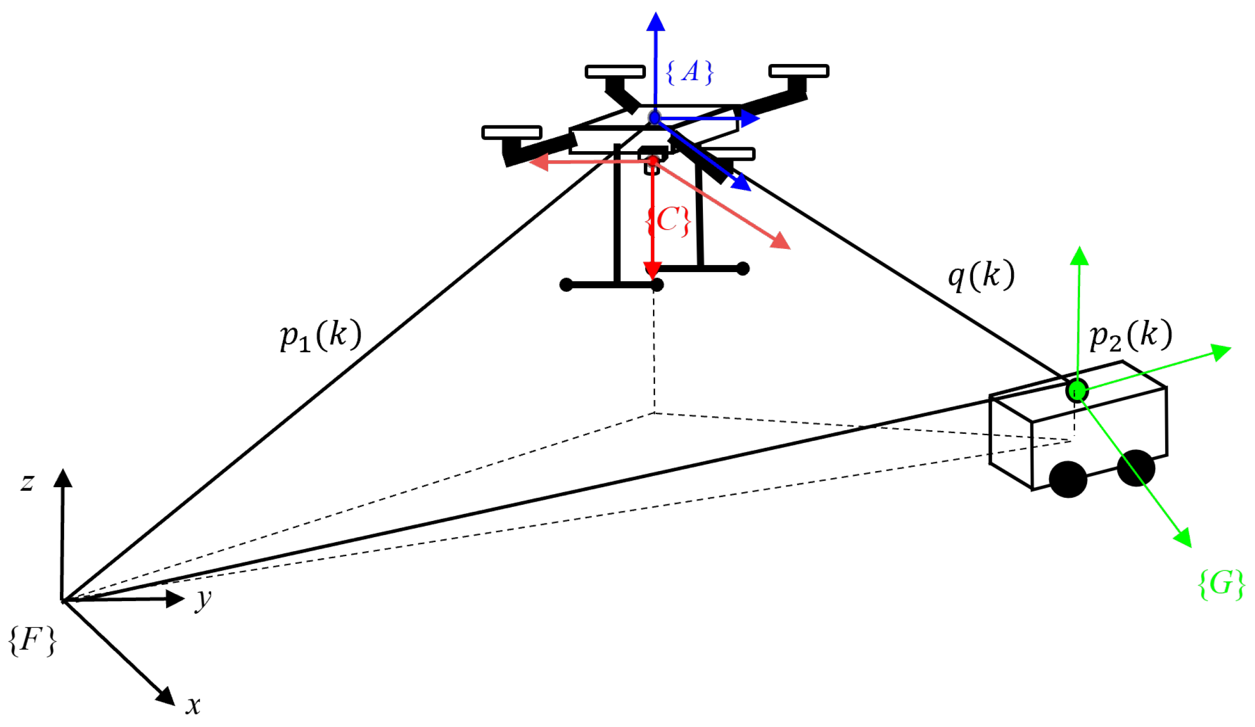
Figure 1. Overview of all coordinate systems.
Drones 07 00613 g001
Figure 2. Relative attitude relationship.
Drones 07 00613 g002
Figure 3. Diagram of landing, where the black–white quadrilateral is the AprilTag.
Drones 07 00613 g003
Figure 4. Autonomous docking framework.
Drones 07 00613 g004
Figure 5. Take-off positioning phase.
Drones 07 00613 g005
Figure 6. Navigation control scheme.
Drones 07 00613 g006
Figure 7. Navigation control scheme.
Drones 07 00613 g007
Figure 8. UAV autonomous navigation approaching trajectory.
Drones 07 00613 g008
Figure 9. The relationship between UAV and UGV in terms of their positions in 3D space.
Drones 07 00613 g009
Figure 10. Parameter estimation analysis.
Drones 07 00613 g010
Figure 11. The UWB sensor measurement data.
Drones 07 00613 g011
Figure 12. UAV autonomous navigation approaching trajectory (double the noise).
Drones 07 00613 g012
Figure 13. The relationship between UAV and UGV in terms of their positions in 3D space (double the noise).
Drones 07 00613 g013
Figure 14. Parameter estimation analysis (double the noise).
Drones 07 00613 g014
Figure 15. The UWB sensor measurement data (double the noise).
Drones 07 00613 g015
Figure 16. Introduction to autonomous docking of UAV/UGV systems. Subfigure (a) shows the hardware setup of the drone. Subfigure (b) shows the hardware setup of the UGV landing platform.
Drones 07 00613 g016
Figure 17. Experimental results of the autonomous docking.
Drones 07 00613 g017
Figure 18. Experimental results of autonomous docking in the UAV’s detection images.
Drones 07 00613 g018
Figure 19. The flight data of UAV obtained through Flight Review.
Drones 07 00613 g019
Figure 20. UWB-measured distance information data.
Drones 07 00613 g020
Table 1. RMS and SD of relative position estimation error, q ˜ , in navigation phases.
Type RMS x RMS y RMS z SD x SD y SD z
MIFG0.40880.65540.32760.3104
FFLS0.63210.79050.39890.4254
Table 2. RMS and SD of relative position estimation error, q ˜ , in landing phases.
Type RMS x RMS y RMS z SD x SD y SD z
UWB0.41220.69020.31270.3250
Visual0.03210.02000.01990.01680.02010.0223
Fusion0.01530.01600.01910.01300.01090.0143
Table 3. RMS and SD of the relative position estimation error, q ˜ , in the navigation phases (double the noise).
Type RMS x RMS y RMS z SD x SD y SD z
MIFG0.51520.58540.51520.5847
FFLS0.76220.80050.58090.6003
Table 4. RMS and SD of relative position estimation error, q ˜ , in landing phases (double the noise).
Type RMS x RMS y RMS z SD x SD y SD z
UWB0.58330.59620.52320.5155
Visual0.05220.03780.02690.02320.02760.0288
Fusion0.01980.01880.02210.02000.01890.0182
Disclaimer/Publisher’s Note: The statements, opinions and data contained in all publications are solely those of the individual author(s) and contributor(s) and not of MDPI and/or the editor(s). MDPI and/or the editor(s) disclaim responsibility for any injury to people or property resulting from any ideas, methods, instructions or products referred to in the content.