1. Introduction
UAVs, also known as drones, are aircraft that are capable of flying without an onboard pilot. They are currently being deployed in versatile applications for military, social, commercial, and leisure purposes. Military UAVs equipped with high-tech surveillance systems fly over dangerous battle zones to provide reconnaissance [
1] and support human-machine teaming. Civil UAVs equipped with thermal and visual cameras are being adopted for assessment of post-disaster damage to public and private infrastructures, such as bridges [
2] and powerlines [
3], as well as surveying disaster sites and acquiring aerial photos for search and rescue operations [
4]. Commercial applications adopt medium size UAVs with hovering capabilities to fly within a vantage range and efficiently acquire aerial live videos for mapping oil and gas pipelines to detect leaks [
5] and for inspection of offshore wind turbines to ensure effective and safe operations [
6]. Furthermore, UAVs with thermal, hyperspectral and visual sensors are being used in agriculture for livestock monitoring [
7] and crop field maintenance [
7]. On the other hand, lightweight small size UAVs are increasingly being used for leisure pursuits, such as for recreational purposes and hobby activities [
8].
Following ground moving targets (GMTs) using UAVs is now possible in an attempt to provide tracking and aerial coverage. A UAV equipped with LiDAR and visual sensors can track the movement of a GMT ahead, or at an impact distance, as well as capture and transmit aerial information about the GMT’s surroundings for further planning. Moreover, tracking GMTs with UAVs serves as the foundation for reconnaissance and surveillance [
9], as well as cooperative helicopter operations [
10]. Throughout the mission, the UAV attached sensor aim point is designated over the GMT [
10] as one of the major aims of these applications. However, adverse weather conditions, such as wind, can impede the mission objectives. In addition, monitoring and following of the GMT movements can be thwarted due to the energy transfer between both the wind and the UAV.
In general, wind can be categorized into two classes based on the properties of the airflow: turbulent and laminar. In turbulent wind, the air particles move with a rapid fluctuation of velocity. One or several factors, including mountains, trees, drastic and uneven changes in thermal gradients, and friction, cause velocity changes. In contrast, laminar wind air particles move with a constant or little change in velocity; therefore, the laminar wind air flows in a smooth path in any open environment. The turbulent and laminar wind disturbances affect UAVs to varying degrees depending on the wind speed, the mass of the air particles, inertia, and the speed of the UAV [
11]. The wind transfers its kinetic and potential energy to the UAV, changing its states, such as roll, pitch and yaw angles, speed, direction, and position. These changes have an impact on the flight path and impede mission goals and objectives.
In the scenario of following GMTs, wind affects the mission’s objectives, such as continuously maintaining the camera aim point on the GMT, providing continuous and steady coverage, and following the movement of the GMT with a fixed standoff distance. Fixed-wing UAVs with rigid wings and airfoils, for example, drift in the wind direction due to wind thrust. To follow the movements of the GMT, fixed-wing UAVs change their yaw angle against the wind direction to generate the required relative velocity; as a result, the camera aim point deviates from its original path and can cause the UAV to be completely out of synchronization with the ground target, thus preventing consistent coverage. Unlike fixed-wing UAVs, multirotor UAVs that have propellers to generate the required force for lift and fly can remain safe and continuously follow the movement of the GMT by changing their roll angle (tilt against the wind) to produce the required force to cancel the thrust that the UAV encounters due to the wind. This tilt deviates the camera aim point from its original path. As, the wind thrust causes the UAV to drift towards the direction of the wind from its original path; so, the camera aim point deviates from its original path. Most of the applications that adopt UAVs for following GMTs have a common component required from the UAV, which is acquiring visual information using the onboard camera. The wind affects the UAV’s position which makes it harder to acquire such information, thereby affecting the camera aim point.
To date, several techniques have been published in the literature on UAV path planning for pursuing GMTs; however, most of them are solely developed for following the GMTs in environments where wind is absent. Real-world flying environments are dynamic and windy; therefore, path-planning techniques that are inefficient in handling wind disturbance are not suitable and are too unreliable to be adopted for UAVs to pursue GMTs and provide continuous camera coverage. Other path-planning techniques that are developed for handling wind disturbances require wind speed and direction measuring sensors which add additional cost and payload. To address these challenges, this paper presents a novel three-dimensional local path-planning technique for multirotor UAVs to follow GMTs in windy environments. The proposed path-planning method does not require wind speed and direction measurement; therefore, no wind measuring sensor is required. The dynamic artificial potential field (D-APF) [
12] is adopted and modified to counter and handle wind disturbances to ensure the camera aim point is always adequately on the GMT and continuous coverage is provided. To accomplish this, the D-APF has undergone two significant modifications. The first modification is introducing a relative displacement component to enhance the sensitivity when the UAV is closer to the GMT in the horizontal plane. The second modification is introducing a standoff distance where the UAV’s roll and pitch angles are modified to control the UAV to always follow the GMT with a standoff distance and maintain the camera aim point on the target regardless of the UAV speed and wind interference.
The remainder of the paper is organized as follows.
Section 2 discusses existing UAV path-planning techniques, such as following GMTs and navigation in windy environments. The proposed path-planning technique is presented in
Section 3.
Section 4 and
Section 5 present the simulation setup and results, respectively.
Section 6 concludes with a summary of the simulation results and future work.
2. Related Work
Few publications exist in the literature for UAV path-planning techniques that handle the wind effect. The optimal time path for a UAV in windy environments that has bounding turning radius has been presented in [
13] by finding the period of maximum bounding rates and straight lines, but this method is a 2D path-planning approach for fixed-wing UAVs and fails in time-varying windy environments. Moreover, this method is solely developed for following GMTs and does not take into account wind effects. Another approach for finding the optimal time path in the presence of wind has been presented in [
14] that is subject to the symmetric constraint on the turn acceleration and turn rate for choosing an adequate turn direction. This is also a 2D path-planning approach that requires an anemometer for wind measurements. A non-cooperative genetic algorithm and the Monte-Carlo technique were adopted in [
15] for finding the collision-free path and the best trajectory in the environment where wind is present, but the chosen route is a random path and is not optimal. The problem of obstacle avoidance and wind disturbances for fixed-wing UAVs has been addressed in [
16] by modelling wind as a 2D vector and modifying the horizontal component of the AA* method. Although the AA* algorithm determines the optimal and collision-free trajectories using an adaptive sampling mechanism, the lack of an ability to handle wind conditions that consist of a vertical component is the main drawback of this method. These path-planning techniques do not consider how wind affects the mission objectives but are only developed for point-to-point navigation in windy environments.
Controlling UAVs to autonomously follow moving targets while fulfilling mission objectives, such as providing continuous coverage or maintaining non-deviant camera aim point under wind effects, is a challenging task. Based on their kinetic properties, these targets can be divided into two categories: stationary targets and mobile targets. Several techniques have been presented in the literature on path planning for pursuing stationary targets under wind effects, such as [
17] for structure inspection, [
6] inspection of offshore wind turbines, and [
18] for small-scale ground target observation. Adopting relative velocity with respect to the wind velocity to calculate the waypoints is the common technique used in these approaches. All these techniques require an anemometer to determine the wind velocity magnitude and direction for handling wind disturbances. However, path planning for simultaneously following GMTs and handling wind disturbances is still a new and challenging research area.
Existing path-planning techniques for tracking the movements of GMTs are mainly formulated as path-planning problems based on the limitation of the UAV type. Fixed-wing UAVs fail to hover and must continue their minimum required airspeed to fly securely in the air. Therefore, the path is planned for following GMTs in a square [
19], circular [
20], or sinusoidal [
21] manner in the horizontal plane, while maintaining the minimum airspeed is the strategy used for fixed-wing UAVs. In contrast, multirotor UAVs are capable of hovering and making quick turns; therefore, few attempts have been reported in the literature for following the movements of GMTs by adopting multirotor UAVs. Fuzzy PI- [
22], fuzzy PID- [
23], and artificial potential field (APF)-based [
24] path-planning techniques are among the prominent approaches. Although fuzzy PI and PID control-based path-planning techniques are capable of following the movement of GMTs, they are vulnerable to collisions with obstacles and may suffer from higher overshoot due to the required computational time for the complex fuzzy functions. The APF-based path-planning techniques, which include dynamic APF (D-APF) [
12] and general APF (G-APF) [
24], produce a smooth path for tracking GMTs while avoiding obstacles in dynamic and static environments. In addition, these APF-based UAV path-planning methods are computationally simpler and easier to implement. However, all these UAV path-planning techniques were developed solely for pursuing GMTs without considering wind disturbances, with no consideration of the fact that the real-world has wind which impedes mission effectiveness.
3. Proposed Methodology
The main objective of any UAV path-planning technique developed for pursuing GMTs is to provide a visual coverage of the target with the onboard camera as well as to physically follow the target with an adequate standoff distance. However, the effect of wind can cause the UAV to drift in a certain direction. To remain safe in the presence of wind, the UAV should tilt against the wind direction. This can cause a drift in the camera aim point and camera footprint path. In such a scenario, the UAV cannot provide continuous and adequate visual support while following the GMT. Existing path planning, such as G-APFs [
24], ED-APFs [
25], and D-APFs [
12], lack the ability to handle wind effects and thus cannot be used in real-world applications because the realistic environment is amorphous and windy. The proposed path-planning technique solves this problem by modifying the attractive force of the D-APF and ED-APF to enhance the sensitivity and by introducing a standoff distance based on the roll and pitch angles which are sensitive to wind speed and direction and to UAV speed.
The proposed path-planning technique generates its velocity and yaw angle waypoints based on the attractive force that pulls the UAV towards the GMT. However, to overcome wind disturbances, the force function is required to generate a higher attractive force for a small variation of the relative displacement, especially when the relative displacement is close to zero. Because the wind can cause the UAV to drift in a certain direction, the APF is required to generate the necessary force for the UAV to maintain its position in the presence of wind disturbances. To produce this wind resistance force, the UAV needs to tilt against the wind, which causes a drift in the camera aim point and path of the footprint. To overcome this limitation, the proposed path-planning technique guides the UAV to a standoff distance from the GMT coordinates based on the UAV roll and pitch angles, which are sensitive to instantaneous wind conditions. This enables the UAV to maintain a non-deviant camera aim point path due to the wind conditions, without relying on the wind speed and direction data.
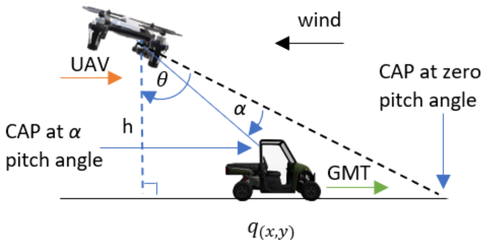
Figure 1, depicts the proposed APF-guided UAV path for acquiring the non-deviant camera aim point (CAP) when the wind is parallel and opposite to the GMT heading; the UAV tilts against the wind to overcome the wind thrust and fly forward, resulting in a non-zero pitch angle. Furthermore, the wind thrust causes the UAV to drift in the direction of the wind. These two factors cause the CAP to deviate from the GMT; therefore, the proposed APF automatically generates the UAV waypoint to follow the GMT with a standoff distance of
parallel to the GMT heading, perpendicular to the GMT heading, and vertical direction, respectively, relative to the GMT position coordinates. The camera gimbal angle and the UAV pitch angle are defined as
and
, respectively. The flight altitude and GMT height are defined as
h and
, respectively.
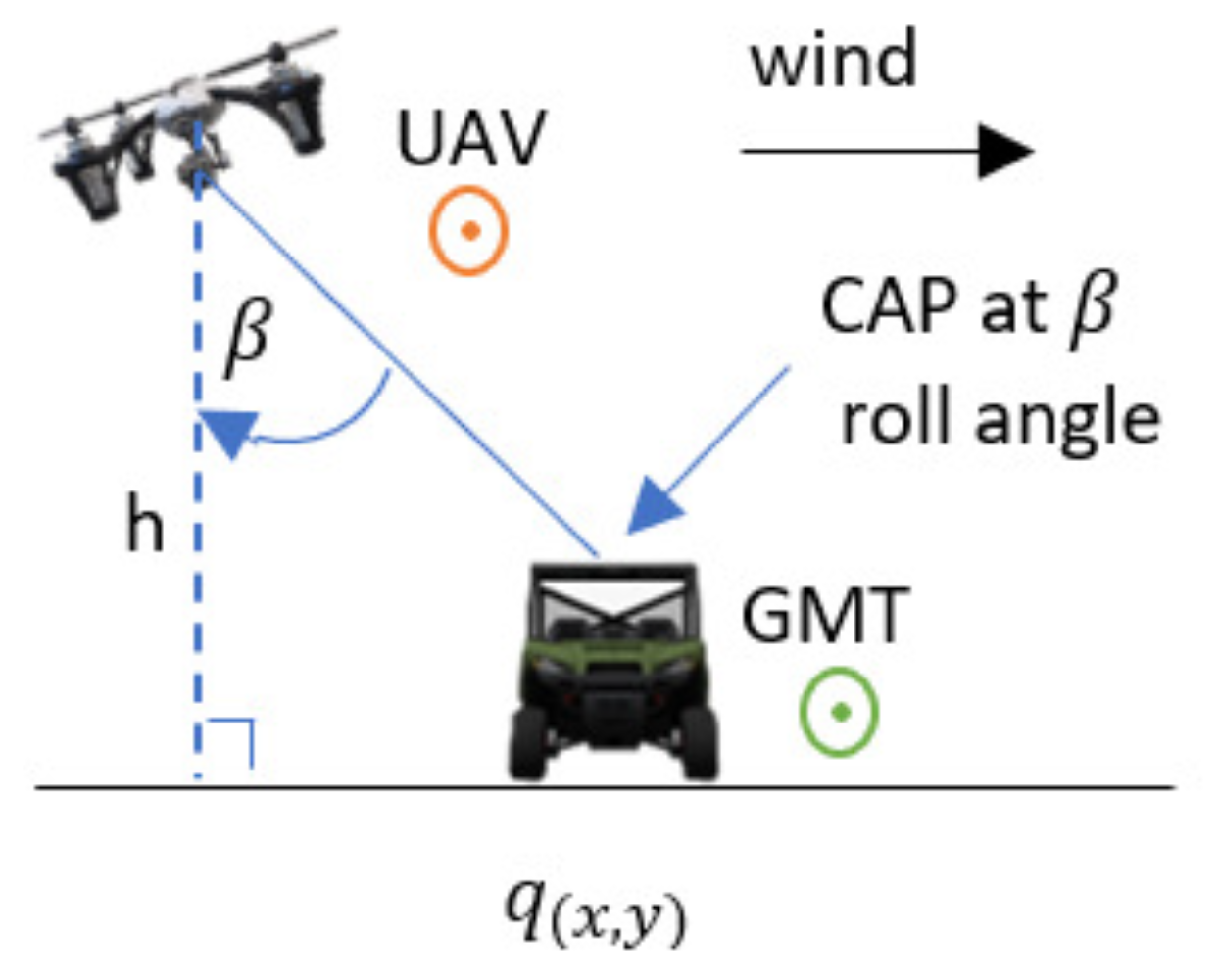
When the wind is perpendicular to the direction of the GMT heading, the wind force drift is in the direction of the wind; therefore, the UAV tilts against the wind by changing its roll angle to cancel the wind force and remain safe in the air. This tilt causes the CAP to deviate from the GMT. To provide the non-deviant CAP, the proposed APF automatically generates the waypoint for following the GMT with a standoff distance of
parallel to the GMT heading, perpendicular to the GMT heading, and vertical direction, respectively, relative to the GMT position coordinates, as shown in
Figure 2. The UAV roll angle is defined as
. The vertical directional wind causes changes to the pitch angle of the UAV that follows the movements of the GMT due to the wind force component acting on the UAV that is parallel to the GMT heading. Therefore, to overcome the wind disturbances and to provide the non-deviant CAP over the GMT, the UAV follows the GMT with a standoff distance as shown in
Figure 3.
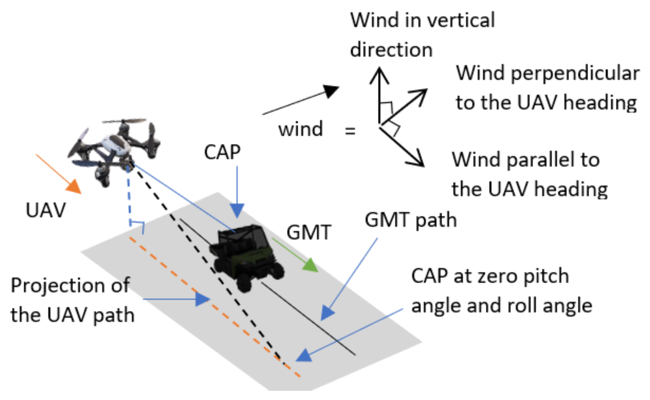
Figure 4 shows the UAV planned path by the proposed APF to acquire the non-deviant CAP when the 3D wind is not parallel or perpendicular to the GMT heading. The 3D wind can be separated into three perpendicular components as wind perpendicular to the GMT heading, wind parallel to the GMT heading, wind in the vertical direction, and then their effects accounted for in an analytical model.
The attractive force
of the proposed APF technique is an exponential function of the relative displacement
and relative velocity
between the GMT and the UAV where
can be expressed using three perpendicular attractive forces: force parallel to the GMT heading
, force perpendicular to the GMT heading
and force along the vertical axis
, as follows:
where
and
are positive constants used to control the minimum relative displacement required to achieve the maximum force. The summation of the positive constant
gives the maximum
in the horizontal direction. The unit vector along the Z direction is denoted by
. The
and
are the relative displacements between the GMT and the UAV in the parallel and perpendicular directions to the GMT heading, respectively. The
is a non-zero vector parallel to the GMT heading. The camera gimbal angle, UAV roll angle, and pitch angle are defined as
and
, respectively. The desired relative altitude between the UAV and the GMT is denoted as
.
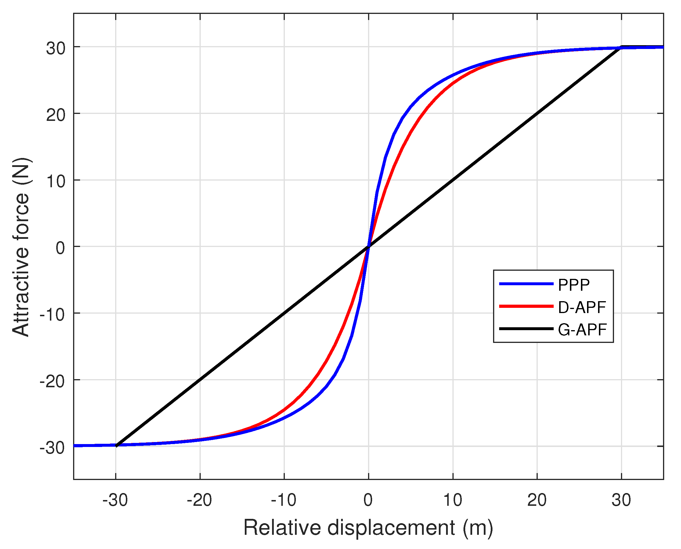
Figure 5 shows the comparison of force distribution of the proposed path-planning technique (PPP) and existing APF techniques, where the gradient close to zero, relative to displacement, is higher for the proposed APF when compared to the D-APF and general APFs. This higher gradient can produce a higher magnitude of
for a small change in relative displacement and it can help the UAV to effectively and quickly maintain its position against the wind, while successfully following the movement of the GMT when the GMT varies its velocity.
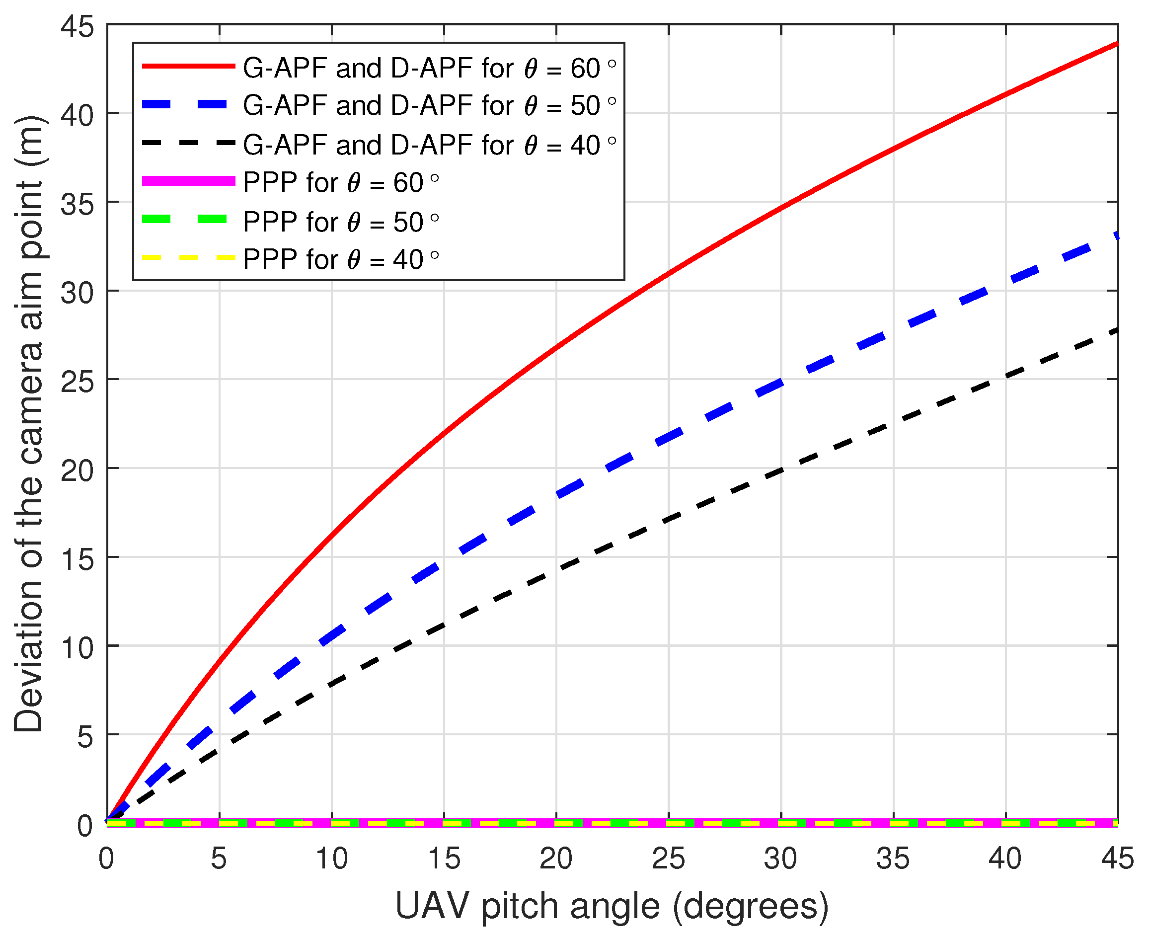
Figure 6 and
Figure 7 show the comparison of the UAV CAP deviation for different roll and pitch angles, respectively. For the G-APF and D-APF, the CAP deviation perpendicular to the UAV heading is independent of the camera gimbal angle but the CAP along the UAV heading is dependent on the UAV camera gimbal angle. While the general APFs and D-APFs CAP deviates from the desired path, the proposed path planning can provide a zero CAP deviation in the presence of roll or pitch angles changes; therefore, the proposed path-planning technique is better suited for following GMTs in real-world scenarios that can cause change in the roll angle due to wind disturbance.
4. Simulation Setup
The proposed path-planning technique was developed using the PX4 software in the loop (PX4-SITL) [
26] supported by a Gazebo [
27] and a robot operating system (ROS) [
28]. To assess the performance of the proposed path-planning technique, several simulation experiments were created for windy environments with different wind profiles, including wind speed and directions that are perpendicular, parallel, and 45° to the GMT heading.
Figure 8 shows the initial simulation setup of the UAV and GMT. The following sections provide these details.
4.1. Gmt and UAV Models
The PX4-SITL unmanned ground vehicle (UGV) ‘Rover’ has been modified and used for the GMT simulations. The UGV was improved to enable it to accomplish a peak velocity of 10 m/s (i.e., 36 km/h) while being controlled by yaw angle rate and velocity waypoints, thus supporting it to change the heading without changing its horizontal coordinates. To support the GMT’s different velocity motion profiles, a set of velocity waypoints with different magnitudes were utilised to achieve the GMT’s constant velocity in the range of 1 m/s to 10 m/s, while the yaw angle rate waypoints were adopted to control the GMT’s direction and heading. In all experiments, the UGV drives in a straight path of 1000 m (1 km) along with the X-axis.
The UAV model used in the simulation scenarios was the PX4-SITL multirotor quadcopter ‘Iris’. This UAV is equipped with an inertial measurement unit (IMU) to determine its heading and velocity, and a global positioning system (GPS) receiver to provide its position coordinates. The UAV has a micro air vehicle link (MAVLink) for communicating with GMT and a flight controller aided by the PX4-autopilot to enable the autonomous mode operation. In autonomous mode, the autopilot accepts velocity, yaw angle, position, and yaw rate waypoints via the MAVLink. An application programming interface (API), MAVROS, runs on the onboard or offboard companion computer to transfer the generated waypoints as inputs to the multirotor UAV’s autopilot at a frequency of 20 Hz.
4.2. Simulation Environment and Wind Profiles
The open plane Gazebo environment was adopted for the multivehicle simulation. The GPS-based relative localization was considered where the GMT communicates with the UAV via the micro air vehicle link (MAVLink). The GMT and UAV simultaneously initiate their motions from
and
, respectively, where the GMT initiates its horizontal motion once the UAV reaches 27 m of altitude at
. The UAV initiates its horizontal motion once it reaches a height of 30 m as this is the minimum height that the UAV should maintain from the ground in Australia [
29]. The UAV attached onboard camera gimbal angle was set at 30
for all experiments.
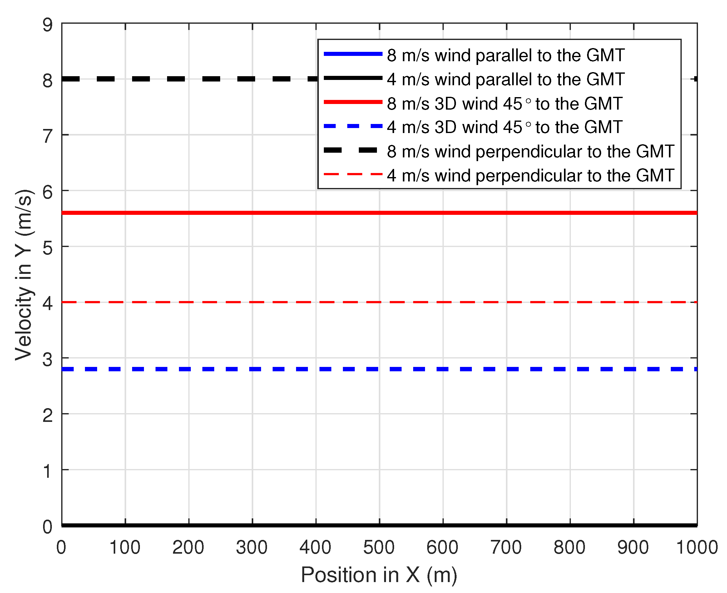
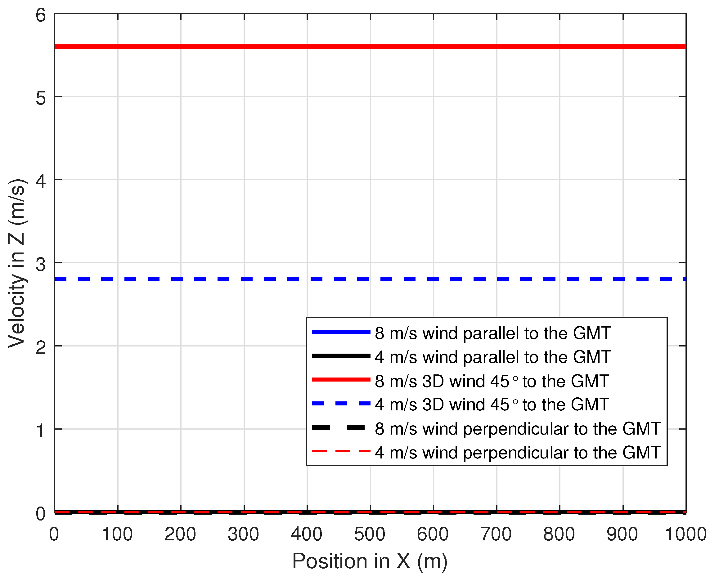
To evaluate the performance of the proposed path-planning technique, different wind profiles were considered. Constant speed winds that were parallel, perpendicular and 45
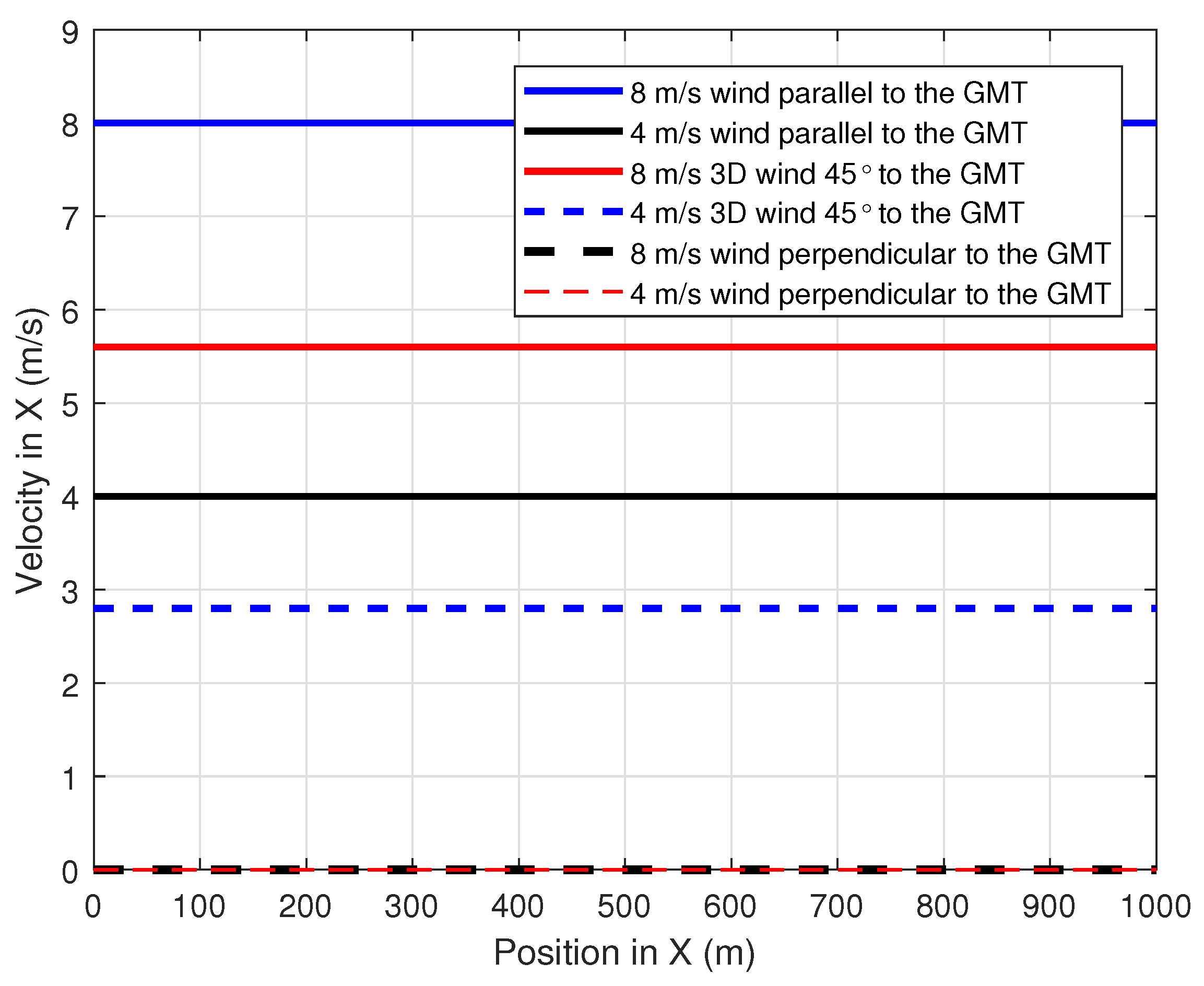
to the GMT path were adopted with a speed magnitude of 4 m/s and 8 m/s.
Figure 9,
Figure 10 and
Figure 11 show the simulation of the wind velocity component in the
X,
Y and
Z directions, respectively, along the
X-direction where the magnitude of each velocity component is constant for a distance of 1000 m.The summation of these
X,
Y and
Z wind velocity vector components give the velocity of the wind that affects the UAV at any given position
X.
4.3. Waypoint Generation
The PX4-SITL ‘Iris’ unmanned aerial vehicle accepts the position, velocity, yaw rate, and yaw angle waypoints. Using velocity waypoints has the advantage of producing smooth motion and change in velocity compared to the position waypoints; therefore, the velocity waypoints were calculated using the proposed attractive force to achieve better aerial coverage. Similarly, yaw rate waypoints were used to eliminate higher turning rates that can hinder the readability of the captured data.
For a UAV with a velocity
, yaw rate
, relative yaw angle
, and mass
m, the next velocity waypoint
and yaw rate waypoint
can be expressed as follows:
where
is the resultant attractive force and
is the waypoints’ transmit frequency to the UAV autopilot.
and
are positive constants.
5. Simulation Results
Four simulation experiments were developed to examine the performance of the proposed path-planning technique. A further two simulation experiments were carried out to compare the performance of the proposed path-planning techniques over the existing force field path-planning techniques. In all experiments, the UAV and GMT start their vertical and horizontal direction motion from
and
, respectively. First, the UAV starts its vertical motion along the
Z-axis. The UAV and the GMT start their horizontal motions once the UAV reaches 27 m of vertical relative altitude with respect to the GMT. During the uplift, the UAV changes its roll and pitch angles to balance the wind thrust where the UAV floats towards the wind direction, as a result the UAV camera aim points cover the
Y and
X axis at
X = 0 when the wind is perpendicular and parallel to the GMT heading, respectively. Once the UAV starts its steady motion, the path-planning technique guides the UAV to provide the non-deviated steady CAP. Two different speeds of the GMT and wind were considered: the 5 m/s (18 km/h) and 10 m/s (36 km/s) of GMT speed along the
X-axis for representing the average speed of a slowly moving vehicle, and a medium-speed vehicle, respectively. The 4 m/s and 8 m/s wind with constant speeds were used for representing the minimum and maximum of the average wind speed at 30 m above the ground using daily wind run measurements as in [
30,
31].
5.1. Proposed Path Planning Performance Evaluation
The first experiment validates the performances of the proposed path-planning technique when the UAV is following the GMT for 1000 m at constant wind speed where the wind is perpendicular to the direction of the GMT: the wind direction is from −
Y to +
Y.
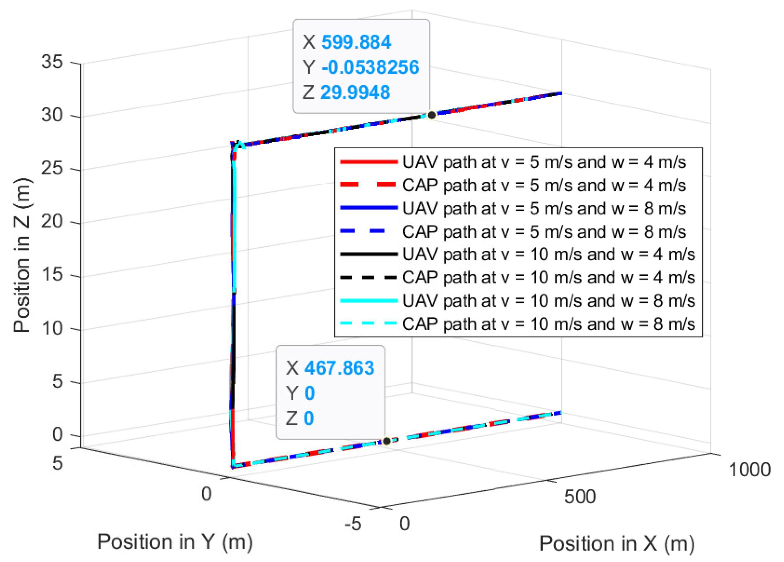
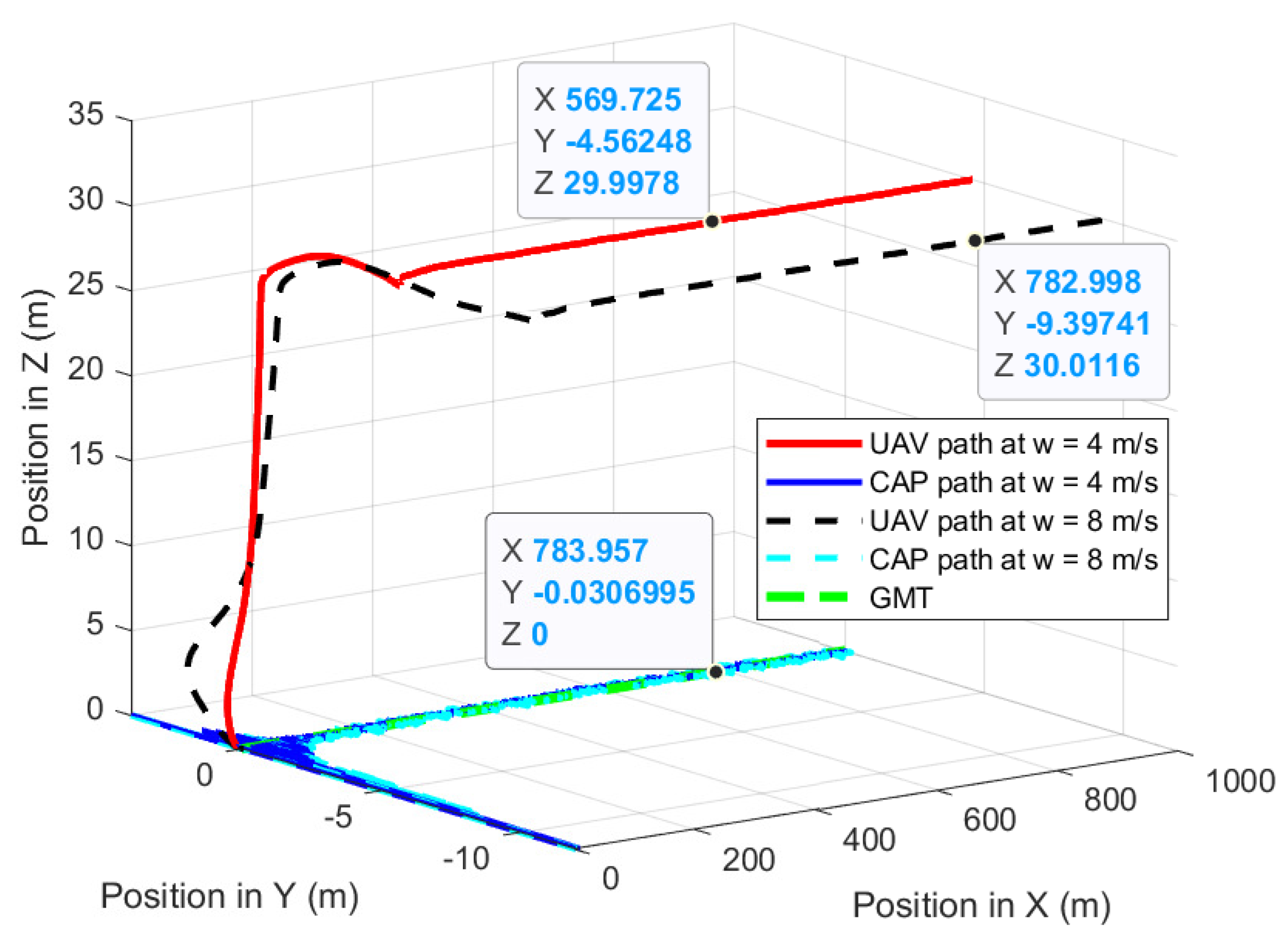
Figure 12 shows the UAV planned 3D path of the proposed path-planning technique for following the GMT and corresponding CAP path at 5 m/s of the GMT speed in the presence of 4 m/s and 8 m/s wind. The proposed path-planning algorithm enables the UAV to change its horizontal position and follow the movements of the GMT with a standoff distance to maintain the UAV CAP on the GMT. This standoff distance is automatically selected by the proposed algorithm based on the roll angle of the UAV, which is sensitive to the wind direction and magnitude.
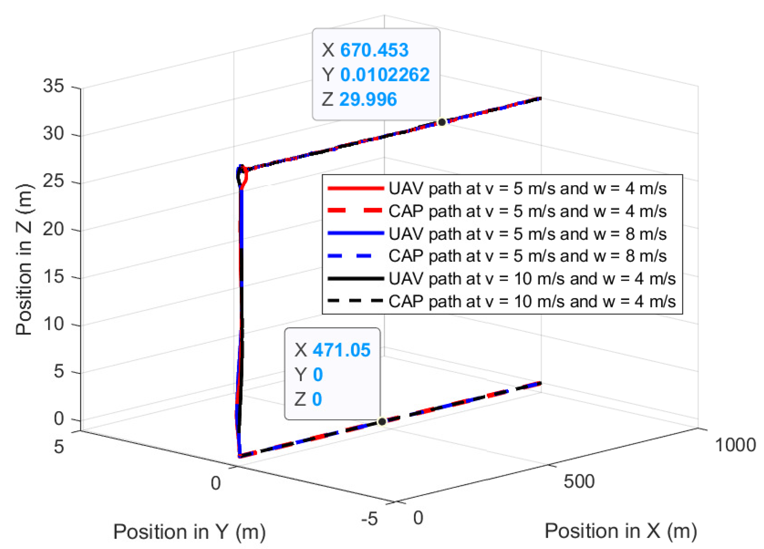
Figure 13 shows the UAV planned 3D path of the proposed path-planning technique for following the GMT and corresponding CAP path at 10 m/s of the GMT speed in the presence of 4 m/s and 8 m/s wind. The UAV has −4.6 m and −9.4 m standoff distances at 4 m/s and 8 m/s wind speeds regardless of the UAV or GMT speeds. This is because, the UAV speed is independent of its roll angle, as the perpendicular wind causes the change only in the roll angle. Therefore,
Figure 12 is similar to
Figure 13 with minimum changes.
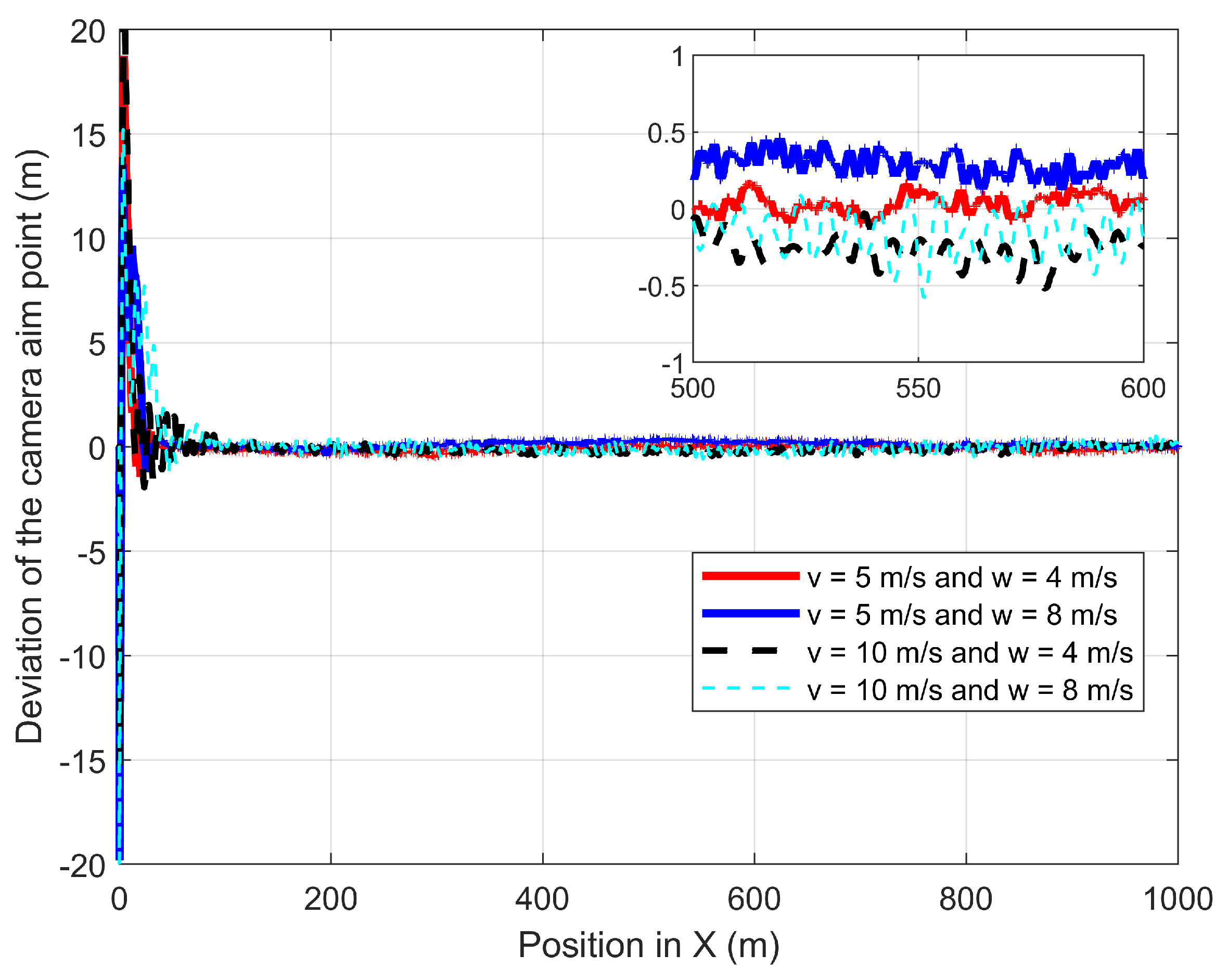
Figure 14 shows the deviation in the camera aim point along the
Y-axis from the GMT path when the UAV follows the GMT. The proposed algorithm successfully maintains the CAP path along the
X-axis with minimum deviation regardless of the wind speed once the UAV starts its steady following of the GMT.
Table 1 depicts the summary of achievements of the proposed path planning in the presence of perpendicular wind.
The second experiment validates the performances of the proposed path-planning technique when the UAV is following the GMT for 1000 m at constant wind speed where the wind is parallel and in the same direction to the GMT heading: the wind direction is from −
X to +
X.
Figure 15 shows the UAV planned 3D path and camera aim point path when the UAV is following the GMT in the parallel and same directional wind where the UAV and the camera aim point path are on the GMT path. The lines on top of each other along the
X-axis show and confirm that the proposed path-planning algorithm enables the UAV to follow the movements of the GMT with the 30 m and zero standoff distance in a vertical direction and Y direction.
Figure 16 shows the deviation in the camera aim point from the GMT along the
X-axis. The wind and the UAV speed cause the change in the UAV pitch angle; therefore, the camera aim point should deviate from its desired position unless the UAV changes its standoff distance. The proposed path-planning technique enables the camera aim point deviation to reach less than 1 m and greater than −1 m by changing the relative displacement between the UAV and the GMT based on the pitch angle of the UAV.
The third experiment validates the performances of the proposed path-planning technique when the UAV is following the GMT for 1000 m at constant wind speed, where the wind is parallel and opposite to the direction of the GMT: the wind direction is from
X to −
X.
Figure 17 shows the UAV planned 3D path and camera aim point path when the UAV is following the GMT in parallel and there is the same directional wind where the UAV and the camera aim point path are on the GMT path. The proposed path-planning algorithm enables the UAV to follow the movements of the GMT with the 30 m and zero standoff distance in the vertical direction and
Y direction. However, the UAV at v = 5 m/s and w = 4 m/s deviates from everything else in the
corner. This is because the UAV changes its pitch angle to provide the required force to cancel the wind thrust; simultaneously with the UAV uplift, the UAV’s roll angle is changed arbitrarily to ensure stability.
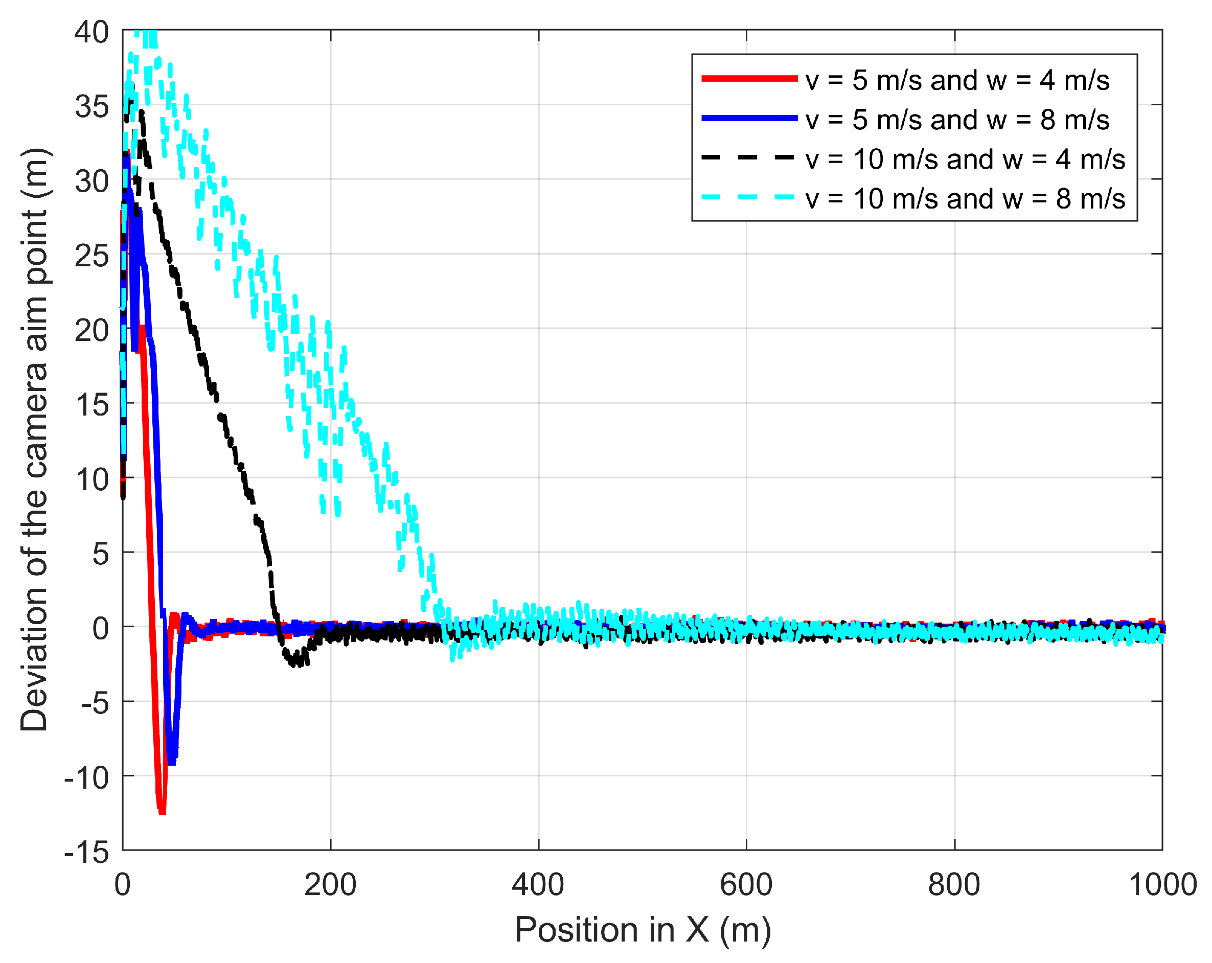
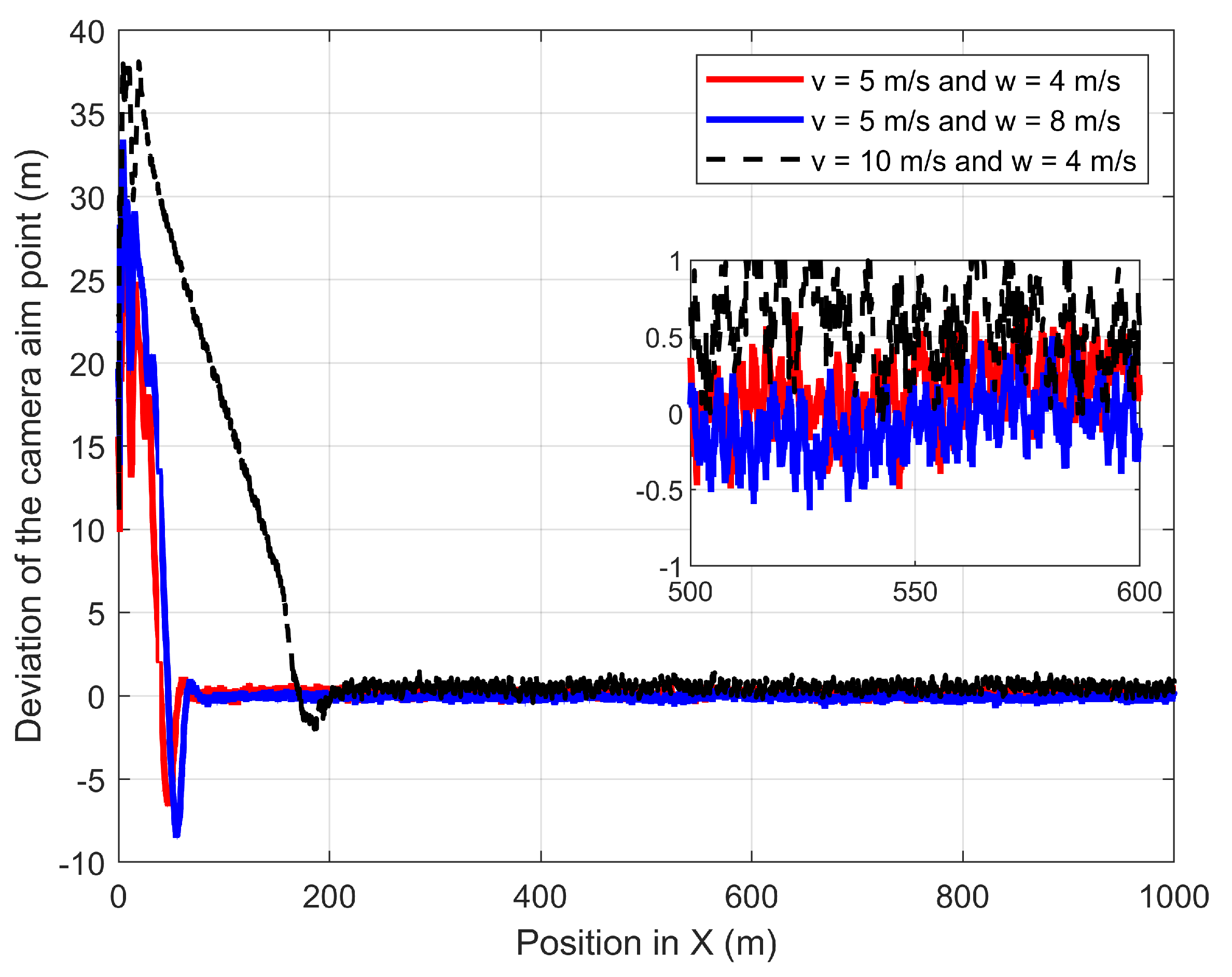
Figure 18 shows the deviation of the camera aim point along the
X-axis. The proposed path-planning technique enables the camera aim point deviation to reach less than 1 m and greater than −1 m by changing the relative displacement between the UAV and the GMT based on the pitch angle of the UAV. However, the UAV requires a higher duration to achieve a steady following of the GMT for higher speeds of both UAV and wind.
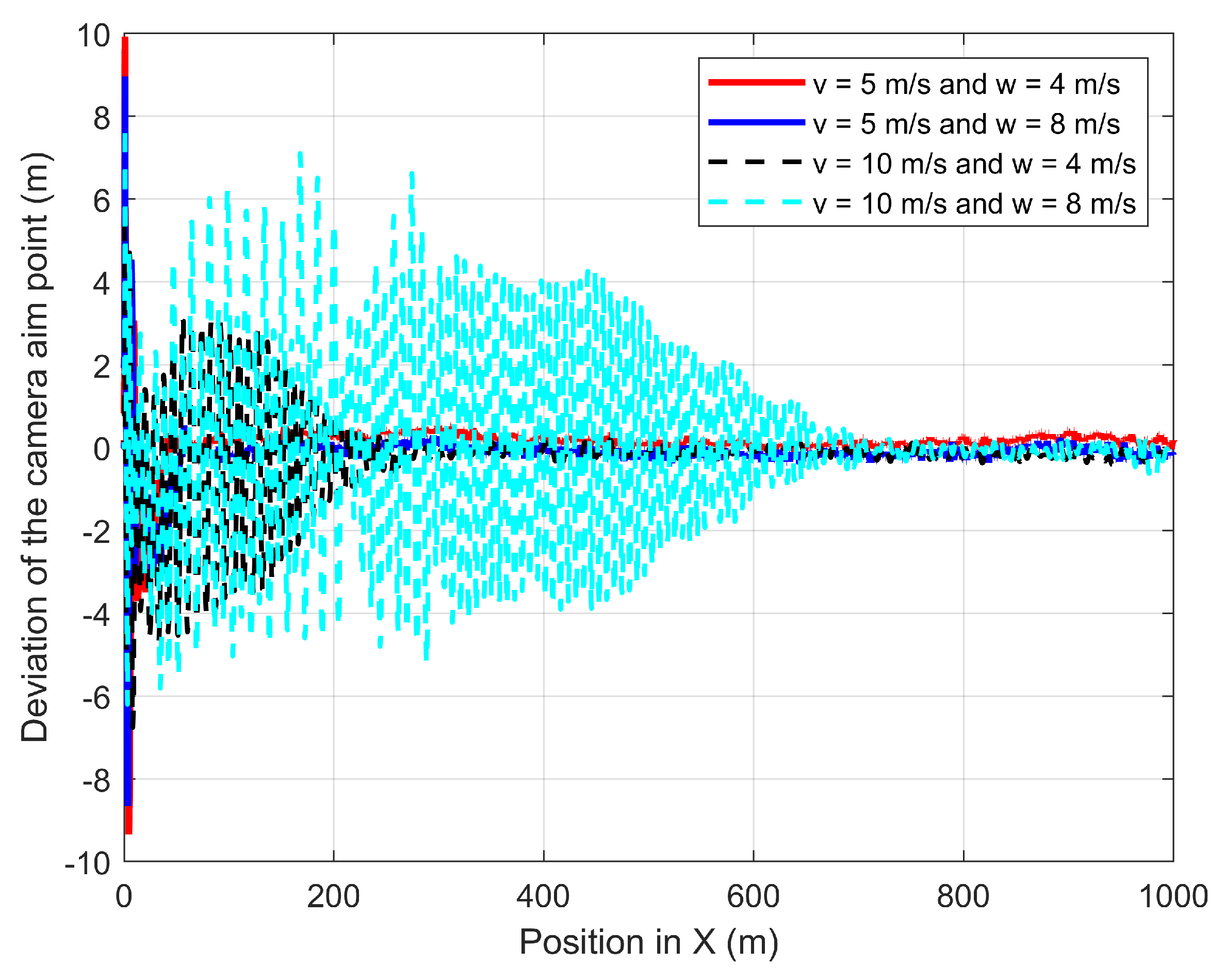
The fourth experiment validates the performances of the proposed path-planning technique when the UAV is following the GMT for 1000 m at constant wind speed where the 3D wind is
to the direction of the GMT.
Figure 19 shows the UAV planned 3D path of the proposed path-planning technique for following the GMT and corresponding camera aim point path. The proposed path-planning algorithm enables the UAV to change its horizontal position and follow the movements of the GMT with a standoff distance to maintain the UAV camera aim point in the desired path. This standoff distance is automatically selected by the proposed algorithm based on the roll angle and pitch angle of the UAV which is sensitive to the wind direction and magnitude. The UAV has a similar standoff distance along the Y direction for the 5 m/s and 10 m/s of the GMT for the same wind speed. This is because the UAV speed is independent of its roll angle, but the perpendicular wind causes the change in the roll angle. However, the standoff distance along the
X-axis has different values for different wind velocities, as well as different UAV velocities. This is because the different wind and UAV velocities produce different pitching angles and relative velocity errors.
Figure 20 and
Figure 21 show the deviation of the camera aim point along the
X-axis and the Y-axis from the desired camera aim point, respectively. The time required to achieve steady following of the GMT increases with the wind speed and UAV speed. However, the forward directional force generated by the multirotor UAV is not sufficient to quickly follow the GMT that is moving at 10 m/s and 8 m/s of wind speed. Therefore, it takes considerable time and distance to steadily follow the GMT and produce a stable and steady camera aim point.
5.2. Proposed Path Planning Performance Comparison to D-APF
To compare the performance of the proposed path-planning technique against the D-APF, two simulation experiments were conducted. The first experiment evaluated the performance of the proposed path-planning technique against the D-APF when the UAV is following the GMT for 1000 m at constant wind speed where the wind is perpendicular to the direction of the GMT: the wind direction is from −Y to +Y. The second experiment evaluated the performance of the proposed path-planning technique against the D-APF when the UAV is following the GMT for 1000 m at constant wind speed where the wind is to the direction of the GMT.
In the first experiment, the GMT moves 1000 m at 5 m/s and 10 m/s along the
X-axis in the presence of wind where the direction of the wind is perpendicular to the GMT heading: the wind is from −
Y to +
Y.
Figure 22 shows the deviation in the camera aim point along the
Y-axis from the desired camera aim point path. The D-APF path planning produces −4.6 m and −9.6 m of deviation from the MGT path for the 4 m/s and 8 m/s of wind speeds, respectively, regardless of the UAV speed; however, the proposed path-planning technique can stay within −0.5 m to +0.5 m of deviation from the GMT path. Therefore, the proposed path-planning technique is more suitable than the D-APF for remote-sensing applications in windy environments.
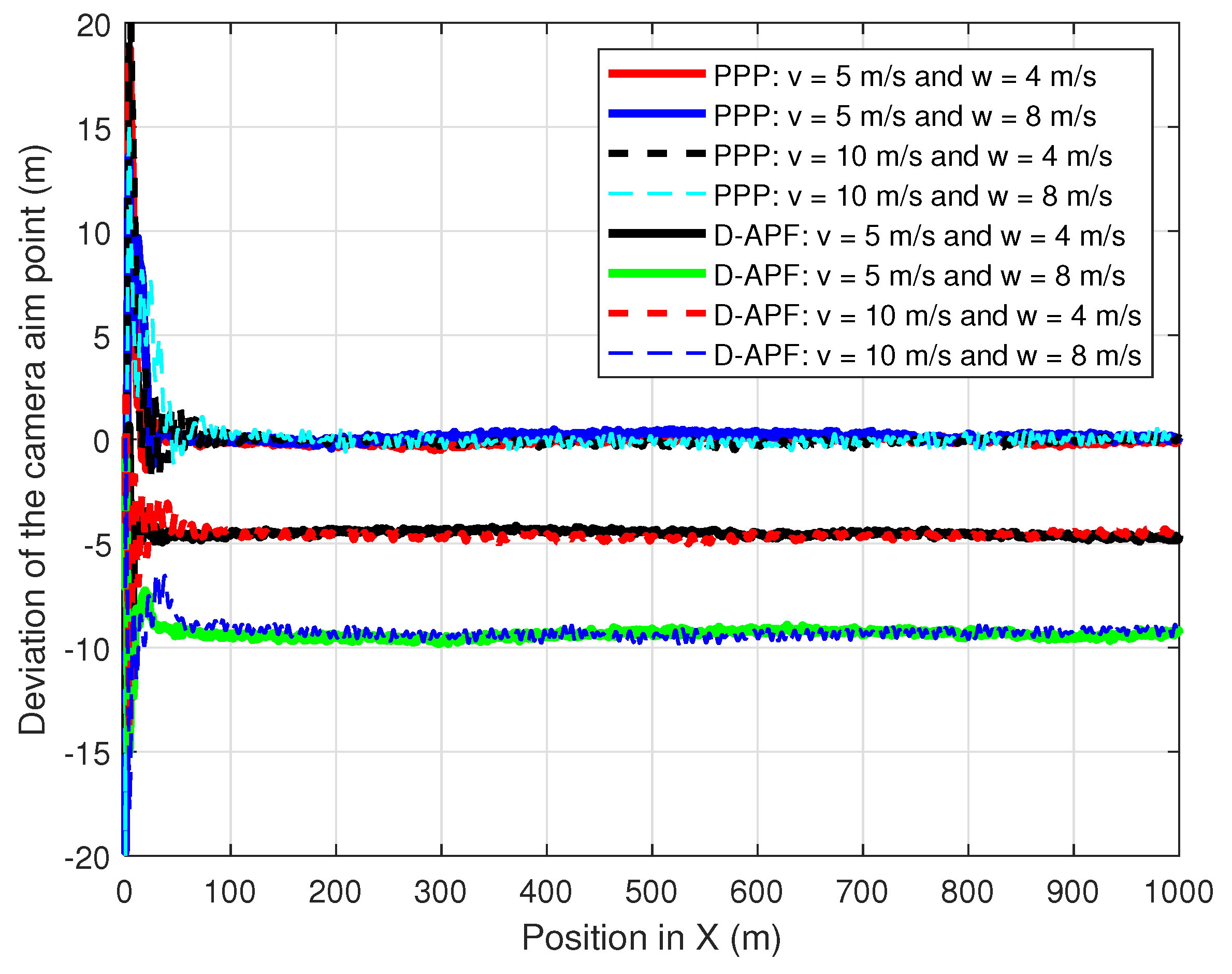
In the second experiment, the GMT moves 1000 m at 5 m/s and 10 m/s along the
X-axis in the presence of wind where the 3D wind is
to the direction of the GMT.
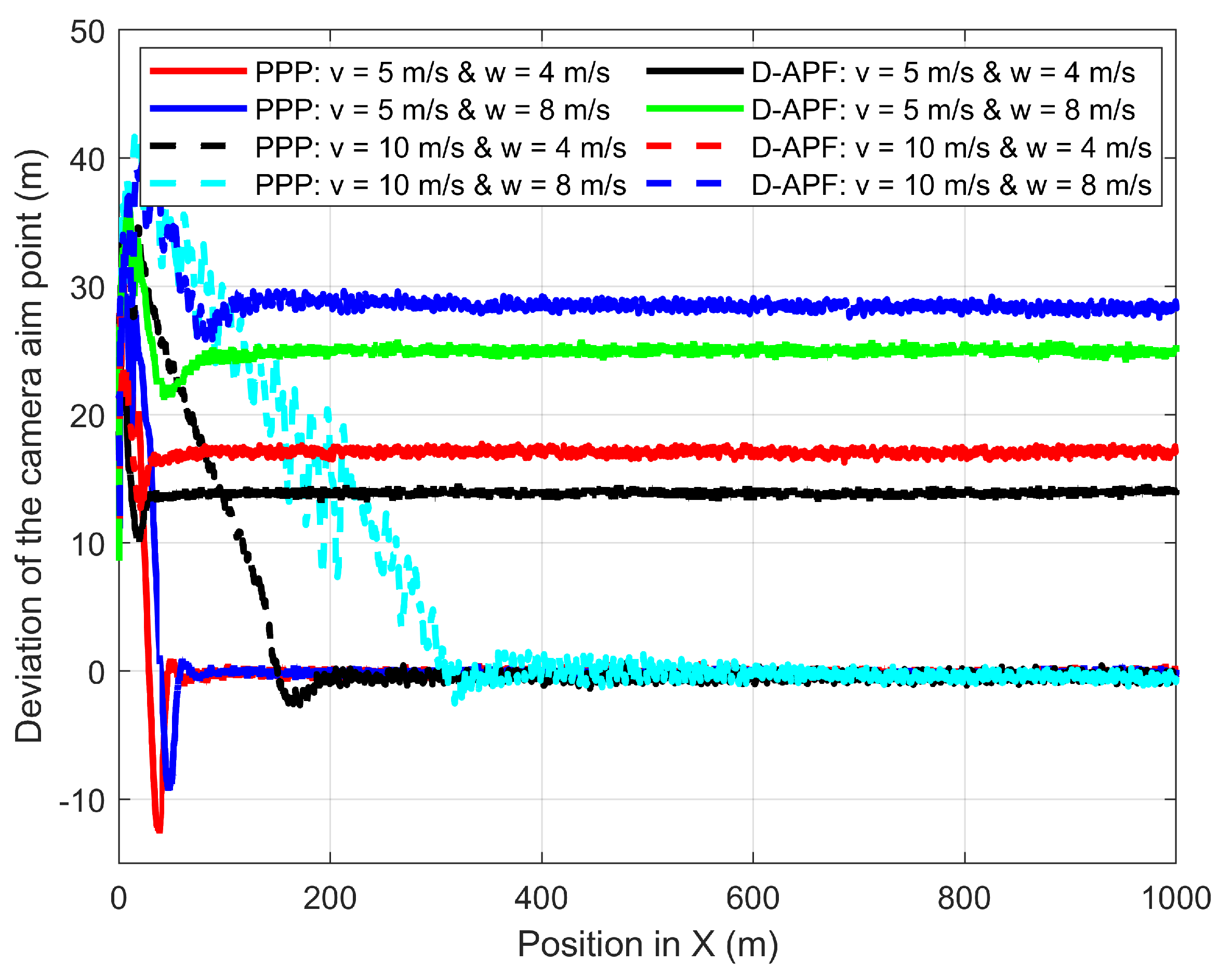
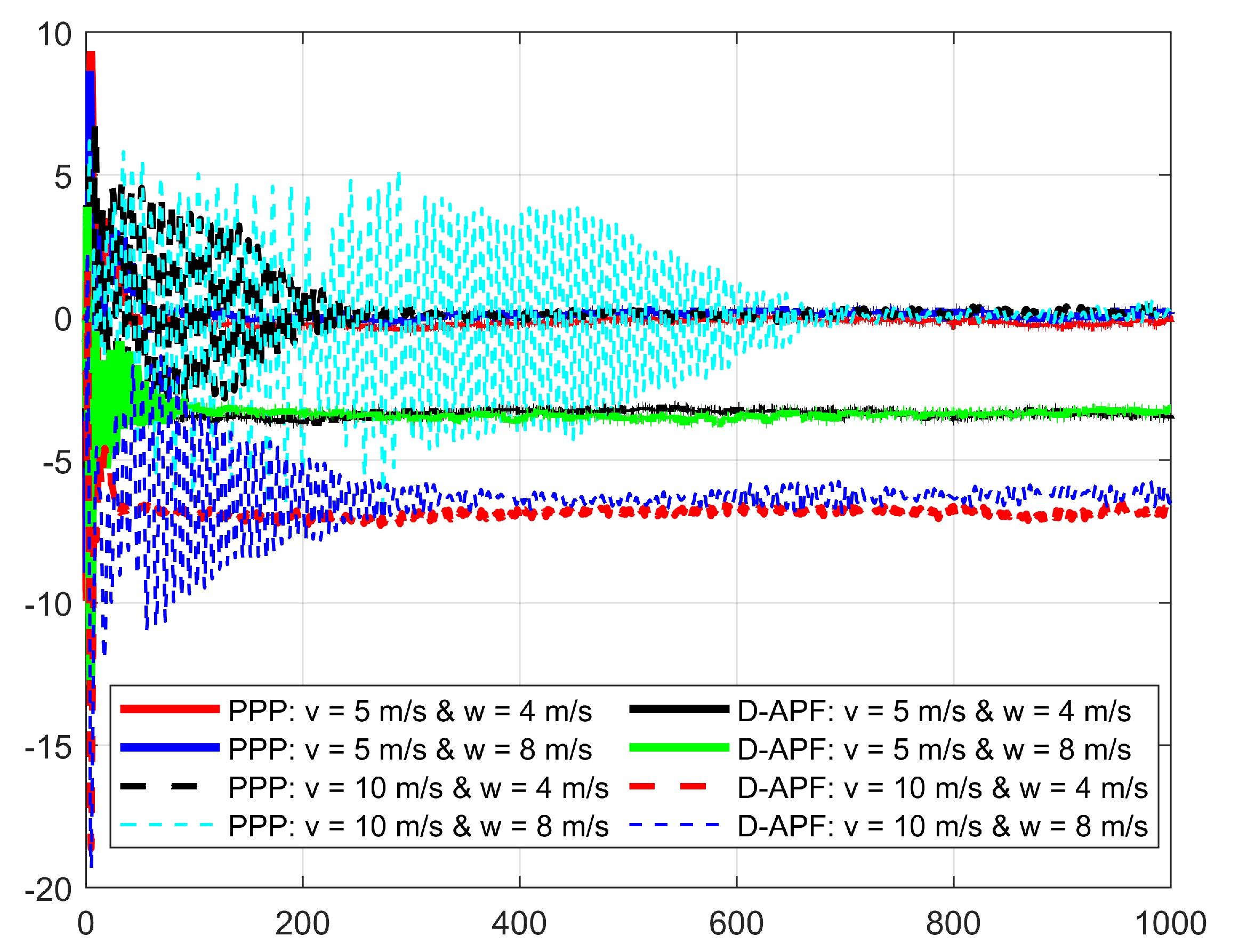
Figure 23 shows the deviation of the camera aim point along the
X-axis from the desired camera aim point path. At 5 m/s of the GMT speed, the D-APF produces 14 m and 17 m of camera aim point deviation for the respective wind velocities of 4 m/s and 8 m/s. At 10 m/s of the GMT speed, the D-APF produces 25 m and 29 m of camera aim point deviation for the respective wind velocities of 4 m/s and 8 m/s. This is because the wind causes the UAV to drift towards the direction of the wind and the D-APF waypoints allow the UAV to tilt against the wind for providing adequate force to compensate for the thrust generated by the wind. Therefore, this drifts and tilt along with the pitch angle generated by the autopilot cause this camera aim point deviation. In contrast, the proposed path-planning technique can stay within −1.5 m to +1.5 m of deviation from the desired camera aim point position which is more than a
decrease compared to the D-APF. This is because the proposed path-planning technique makes the standoff distance based on the pitch angle to keep the non-deviated camera aim point. In addition, the proposed path planning has better performance in terms of camera aim point deviation along the
Y-axis, as shown in
Figure 24. Therefore, the proposed path-planning technique is more suited than the D-APF for remote-sensing applications in windy environments.
6. Conclusions
In this paper, a novel three-dimensional online APF path-planning technique has been proposed for multirotor UAVs to follow GMTs and provide a steady and non-deviant camera aim point over the GMT in windy environments. The proposed path-planning technique does not require wind speed or direction to overcome the wind disturbances; therefore, it does not need costly and power-consuming wind-measuring sensors. The D-APF has been modified by introducing a standoff distance and improving the sensitivity for a small change in relative displacement to achieve a smooth and better force to ensure the camera aim point is always adequately on the GMT regardless of the speed of the GMT and the wind conditions. The proposed standoff distance is wind sensitive and is a function of the UAV flight altitude, pitch, and roll angles. The proposed path-planning technique can be adapted for any kind of typical multirotor UAV that has a flight controller with an autopilot, GPS receiver, and MAVLink.
Using ROS and Gazebo-supported PX4-SITL, the proposed path-planning techniques were validated in different wind conditions, including different wind velocities and GMT speeds. The simulation results confirm that the proposed path-planning technique can achieve less than 0.41 m of camera aim point deviation from the GMT that has 10 m/s maximum speed and for a wind that has 8 m/s maximum speed. The simulation results demonstrate that the camera aim point deviation depends on the UAV velocity and wind velocity; therefore, using roll and pitch angles should be more effective than using wind measurement to overcome the camera aim point deviation.
The proposed path-planning technique’s performance was compared to that of the D-APF path-planning technique. The simulation results confirmed that the proposed path-planning technique can reduce camera aim point deviation by more than when compared to the D-APF; thus, it outperformed the D-APF in terms of camera aim point deviation when tracking the GMT’s movements in a windy environment. As a result, the proposed path-planning technique is better suited for real-time application scenarios in windy environments.


