Abstract
On-demand air transport is an air-taxi service concept that should ideally use small, autonomous, Vertical Short Takeoff and Landing (VSTOL), “green”, battery-powered electric aircraft (eVSTOL). In addition, these aircraft should be competitive with modern helicopters, which are exceptionally reliable machines capable of the same task. For certification and economic purposes, mobile tilting parts should be avoided. The concept introduced in this paper simplifies the aircraft and makes it economical to build, certify and maintain. Four contrarotating propellers with eight electric motors are installed. During cruise, only two of the eight rotors available are not feathered and active. In the first step, a commercial, certified, jet-fueled APU and an available back-up battery are used. A second solution uses a CNG APU and the same back-up battery. Finally, the third solution has a high-density dual battery that is currently not available. A conceptual design is shown in this paper.
1. Introduction
On-demand air transport is an air-taxi service concept that should use small, Vertical Short Takeoff and Landing (VSTOL), battery-powered, electric aircraft (eVTOL). These aircraft should be competitive with modern helicopters, which are exceptionally reliable and cost-effective aerial vehicles designed for the same task. These new vehicles should be more efficient, less expensive, eco-friendly, and quieter than helicopters and autogiros. A few considerations are necessary before the introduction of an innovative design concept for the task. First, autonomous flying is possible [] and relatively straightforward, with the aid of today’s machine learning technologies [,,]. Most commercial airplanes have the capability of fully autonomous flight from takeoff to landing []. Many Unmanned Aerial Vehicles (UAVs) have the capability to fly a mission autonomously even in controlled airspace and in airports. Nevertheless, unmanned flight is rarely considered for civil air transportation []. This is because most passengers would refuse to use a pilotless airplane. Therefore, from the perspective of an individual who communicates with their destination via an app, the notion of securing their seatbelt, closing the door, and taking off for a fully autonomous flight is physiologically uncomfortable. What would happen in case of an emergency? The air-taxi would be controlled by an emergency ground station. How would the control authority expect such an aircraft to fly over a crowded city, with other aerial vehicles? For this reason, it is important to design an optionally piloted vehicle. In this case, at least for an initial period, a pilot could transport the passengers to their destination. Theoretically, electric propulsion introduces the potential to alter the design of vertical lift vehicles for reduced cost. Experts theorize a substantive operating cost improvement because of lower energy costs, reduced maintenance time, mass production, and increased part commonality []. In fact, energy coming from the electrical grid costs less than one third of that obtained on-board from aviation fuel. Only for this reason, a 6% reduction comes directly from the 20% share of fuel in terms of the operating costs for helicopters. Electrical propulsion is also expected to reduce maintenance by 20–30% due to the elimination of gearing and transmission. Unfortunately, battery-specific energy is a critical constraint for all electric aircraft, since the vehicle gross weight increases rapidly as the specific energy is reduced. The new concept proposed in most papers relies on batteries that do not exist. To certify an aerial vehicle, one must use a certified battery pack, with cells that are produced to a sufficient quality level. Today, this quality level is one failure over 200 million cells for the whole battery life. Today, batteries need a Battery Management Unit (BMU) with a reliability of more than one minor failure over 30,000 flying hours []. The BMU should equalize the charge of all the cells. In 2023, the required number of cells will be equal to 3000 for a 100 kWh battery. The BMU should also check the cells. It will discharge all the units that are damaged or significantly aged, beyond recovery. The BMU also controls the charging and discharging current, which depends on the battery temperature, cell age, and the type of charge (fast or best). The BMU should also contain safe braking systems for misuse or crash. Today, a thermal and mechanical barrier is required to protect the aircraft from thermal runaway of the cells and piercing of the unit in case of crash. In addition, the efficiency of battery charging and discharging depends on several factors. Current, temperature, and age are the most important []. It is important to note that the second law of thermodynamics states that as energy is transferred or transformed, a part of it is wasted; therefore, battery charging and discharging never have unitary efficiency. For these reasons, the battery should be cooled or heated []. Today, it is appropriate to design a vehicle that uses aircraft-certified eAPUs, with the possibility to update the vehicle to retrofit the future battery later as it becomes available. In fact, in a few studies found in the literature, the eVTOL aircraft was designed with a futuristic 300–400 W hr/kg battery [,]. Air transportation safety requires the use of already tested power packs, and costs require the use of mass-produced batteries. Therefore, the easiest way to obtain the real, commercially available power density is to adopt existing power packs that are widely used in the automotive market for electrical vehicles (EVs). Table 1 shows acceptable ranges for Volumetric Energy Density (VED) (Wh/dm3) and Specific Energy Density (SED) (Wh/kg).
Table 1.
VED and SED values for commercial batteries [].
The Tesla car manufacturer has successfully applied a 4416-cylinder-cell-unit that weighs 478 kg and stores 75 kWh to Model 3. This means an SED of 157 Wh/kg. This power pack is approximately 1200 mm wide, 1900 mm long, and 100 mm thick for a VED of 328 Wh/dm3. The modules are cooled with a fan-equipped radiator. A liquid-cooled electronic system controls the battery temperature and outputs the DC current at the nominal voltage of 400 V. The complete “PowerWall 2” power pack, also from Tesla, has an SED of 106 Wh/dm3 and a VED of 118 Wh/kg. Nonetheless, actual technology is far from the level of 400 Wh/m3 assumed by a few authors [,]. In addition, fast discharge during vertical takeoff and landing will face lower efficiency with loss of energy. “Fast charge” cycles of 40 or 60 min each would also significantly reduce battery life. For this reason, now, it is necessary to consider the possibility of changing the battery pack instead of recharging it. Many companies are working on eVTOL designs, including Airbus, Boeing, Honeywell, Joby Aviation, Terrafugia, Lilium Aviation, and Aurora Flight Sciences. Quite unique design approaches are available: a tiltrotor, tilt-duct, tilt-wing, and separate rotors for cruise and hover; as well as a multirotor, autogiro for conventional and compound helicopters; finally, a tilt-duct forcoaxial-rotor helicopters, and compound helicopters. Another problem is certification. From the authors’ experience, based on the Agusta-Bell 609 certification [], authorities will require a nearly complete certification for each degree of tilt of the moving parts, with the exception of the feathering propellers that have a separate certification path. In addition, certification authorities will require this situation to be handled if one or more of the movable parts is locked in a fixed position by a failure, or alternatively, will request complete actuating systems shut off [
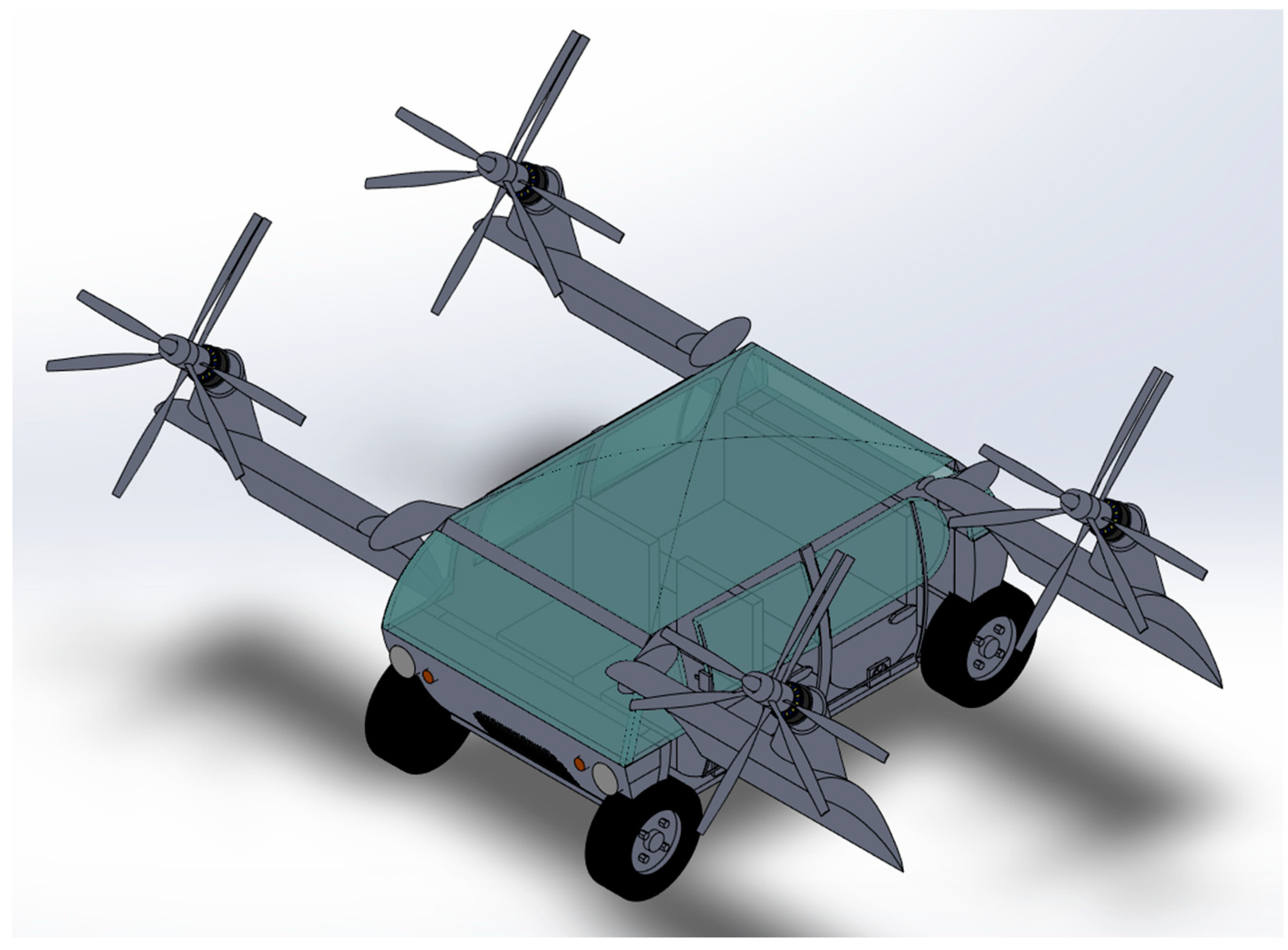
]. Proper recovery systems should be considered for every failure combination and included in the pilot’s notes. Very efficient systems such as ballistic parachutes may prevent the use of the aerial vehicle in urban areas. For this reason, this paper introduces a new concept for a hybrid air-taxi, based on attitude changing and not on rotating parts or additional propulsion systems. The concept is based on the Opener BlackFly idea [
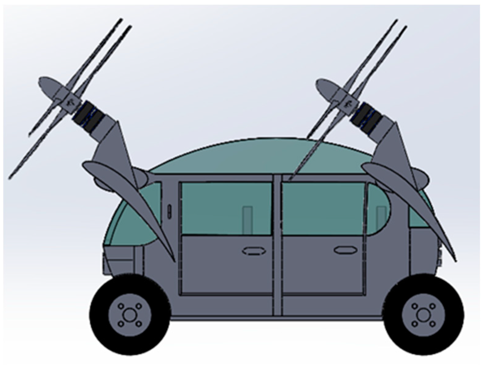
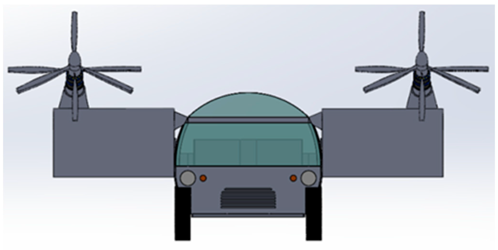
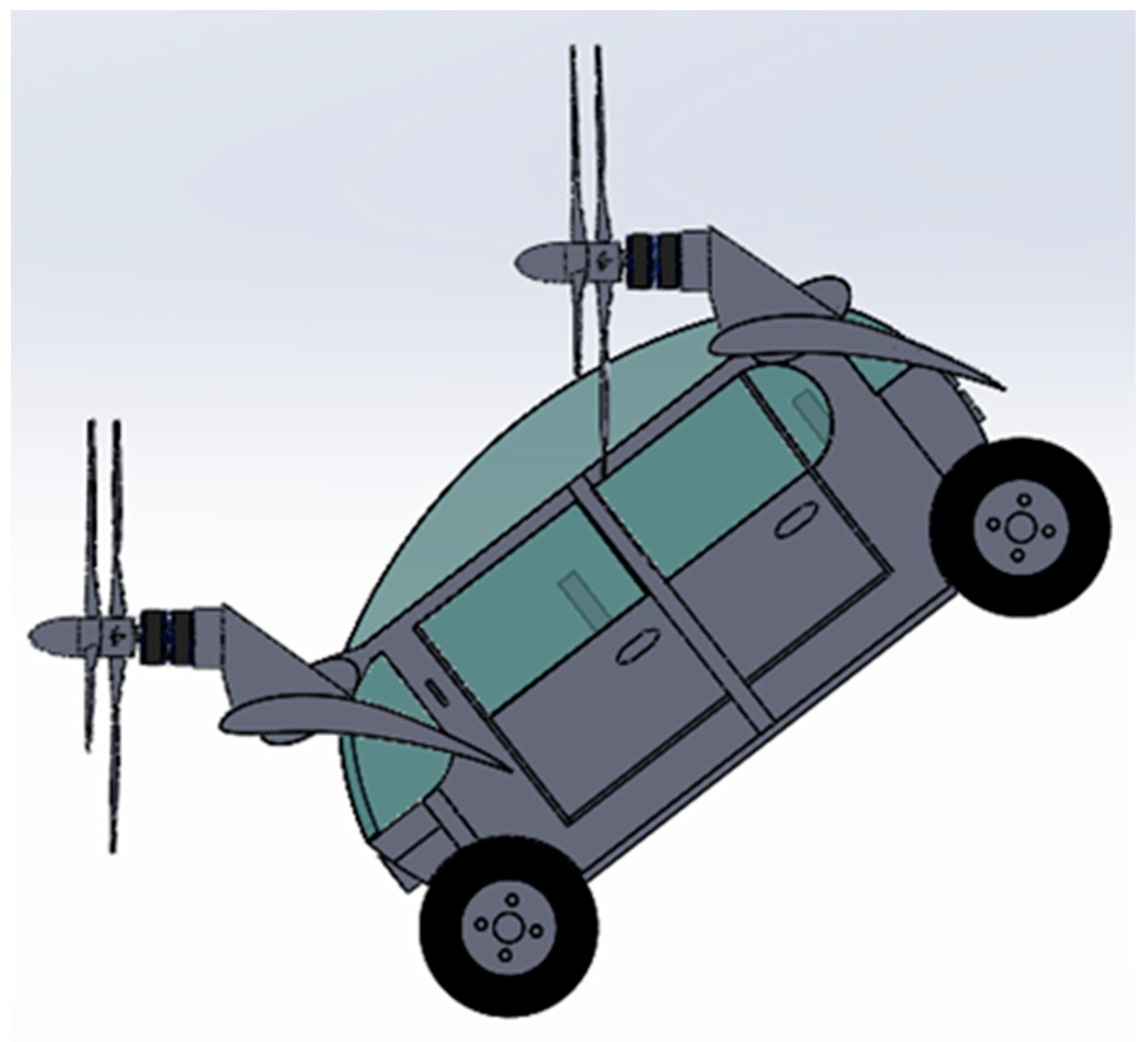
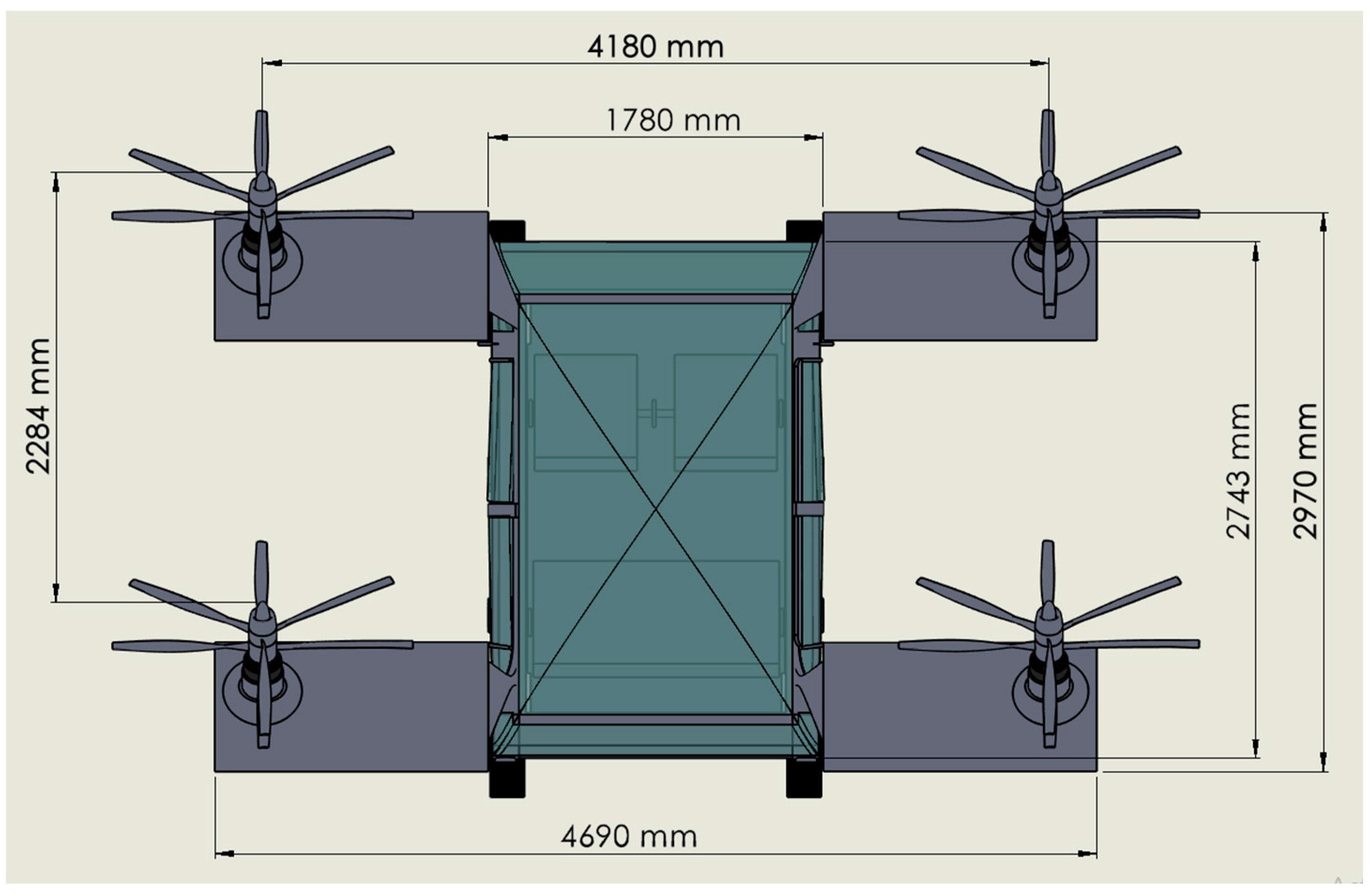
], with modifications for the air-taxi application. Therefore, the vehicle has already been flight evaluated in a slightly different configuration. The authors replaced the original multimotor–rotor configuration with four identical contrarotating propellers. In addition, an undercarriage was added for taxiing. An APU was installed for range extension. The original two-seater configuration was replaced with a five-seat fuselage.
2. Materials and Methods
2.1. Requirements
The release of the Uber Elevate White Paper defined the requirements to make urban air-taxi profitable. A few of these requirements are summarized in Table 2 []. Table 3 also shows some important values about eAPU.
Table 2.
Requirements from Uber Elevate White Paper.
Table 3.
eAPU data [].
Unfortunately, the battery requirements correspond to much better units than those currently available on the automotive market. In fact, the Uber Elevate documentation claims an SED of 400 Wh/kg, while the absolute best automotive units only have an SED of 200 Wh/kg. The same difference applies to recharging time. This is a problem since automotive requirements are less stringent than aircraft certification ones. Therefore, batteries for certified aircraft are less efficient than the latest used in the automotive market. Therefore, the authors have included a power pack in this preliminary design that can be composed of a jet-fueled eAPU (electric Auxiliary Power Unit) currently in use in a last generation helicopter (AW 189). In this case, the eAPU is already certified and the process of the aircraft certification is rather simple. Alternatively, the APUs can use CNG (Compressed Natural Gas) that is a quite common and simple technology and the adaptation to eAPUs is straightforward. It is also possible to use a piston engine for the CNG-APU, with much better efficiency at the required power levels. A fourth, future alternative is to use a detachable battery powerpack that is replaced instead of being recharged. In this case, a twice-redundant battery pack is designed for flush installation into the aerial vehicle. The twin battery redundancy is for safety even if, in most conditions, the vehicle may be capable of autorotation. A fourth alternative is to use a fixed battery to be recharged directly in the eVTOL vehicle. In the case of batteries, it is convenient to try to design droppable units. In fact, today, batteries once on-fire cannot be extinguished with actual technologies. It is also advisable to have an emergency strategy available for each of the flight legs. Modern helicopters have hundreds of unique moving parts that are assembled into modern helicopters. The secret of their reliability lies in the frequent maintenance by qualified personnel that use certified components and procedures. The new aircraft should have fewer unique components and fewer dynamic components that should translate to a substantial cost reduction during the life of the vehicle. For the cost comparison, an aerial vehicle similar to this air-taxi is the Robinson R44, single-piston engine helicopter. The nimble R44 is a very low-cost helicopter with two bladed main and tail rotors. Its payload is close to the Uber Elevate (800 lb for four passengers), and this helicopter can meet the Uber Elevate range requirement, being capable of 300 mi. In fact, the air-taxi is an atypical aircraft due to the incredibly low range achieved (60 mi) and the relatively low cruise speed (160 mph). Its competitor (Robinson R44), as any rotary wing aircraft, is not very fuel-efficient when compared with a fixed-wing aerial vehicle. For this reason, the new, fixed-wing design should also be atypical and should give priority to cost, safety and handling. Aerodynamic and propulsion efficiency are in second place. The impression given to the customers should be closer to a taxi than to an airplane. Maintenance and purchase costs should be as low as possible. However, the concept is to design a small vehicle capable of operating autonomously from parking with a driver (pilot), four passengers and a small weight of luggage. The use of CNG (or H2) instead of other fossil fuels will minimize the environmental impact. Safety is obviously of paramount importance and a fail-safe design should be adopted. The maintenance skill required should be closer to a car than an airplane. Finally, computer-assisted flight control would reduce the pilot workload to a minimum.
2.2. Configuration Selection
Electric and thermal–electric hybrid propulsion allow far larger design freedom without the constraints and mechanical complexity of drive systems and shafting. However, the physics is still there, and the aerial vehicle should have low disk loading to limit takeoff power. Unfortunately, the same vehicle would need higher disk loading for high cruise efficiency []. Moreover, the wings cannot be too large, with the wingspan being limited by the footprint. The vehicle should be as simple as possible to improve reliability and reduce maintenance. The selected starting idea is the Opener BlackFly [] (US Patent US20140097290A1). This single-seater ultralight aircraft has a tandem wing configuration with winglets. Each wing is equipped with four tractor propellers canted up at 45 degrees. The entire aircraft changes pitch to accommodate the different flight configuration. At vertical takeoff, the aircraft pitches up 45 degrees to make the propellers pull vertically. For best-efficiency horizontal cruise, the aircraft pitches down 45 degrees, with the propellers aligned with the flow-stream. The BackFly has no landing gear, and the bottom fuselage is protected by a rub-strip and small rubber bumper on the curved bottom of the hull, which makes it possible to operate from a grass surface, asphalt, and water. Dual elevons on the outer edge of both wings and differential motor speeds provide control authority. Unpowered glide mode is also possible. The large advantages of this configuration are the relative simplicity, the controllability in the vertical flight mode, the easiness of transition from hover to forward flight and the possibility to fly powerless. The drawback is the high fuselage drag in cruise and the lack of mobility on the ground. The last drawback was eliminated by the author’s patented innovative design (Figure 1, Figure 2, Figure 3 and Figure 4).
Figure 1.
Side view of proposed solution parked.
Figure 2.
Frontal view of proposed solution parked.
Figure 3.
Side view of the vehicle in cruise attitude.
Figure 4.
Side view of proposed solution nearing the vertical takeoff condition, with the rear wheels still on the ground for directional control.
In the vehicle in Figure 1, the rear wheels are motorized to make it possible to move the vehicle on the ground autonomously. It is also possible to avoid motorized wheels, but the propeller propulsion is dangerous for people nearby. Like in a car, all the wheels have brakes. The fuselage resembles an early Volkswagen Typ2 T1 “Samba” (1954). The ceiling is rounded to provide improved aerodynamics in cruise mode and it is transparent for better visibility. Fuselage aerodynamic efficiency is sacrificed for functionality. In any case, the flight distance would not be extended. The vehicle would take less than half an hour for the longest 60 mi distance. The extremely small power pack (eAPU; Table 1) is positioned in the rear part. A battery is installed in the bottom of the vehicle to stabilize the current from the eAPUs and to lower the GC (Gravity Center). An alternative position is in the frontal part. This position allows the battery to be replaced on site without special tools. A small baggage compartment is positioned in the rear over the eAPU. On the ground, the vehicle operates like an ordinary car with the frontal wheels steering and the rear ones providing traction. Since the amount of power required is exceedingly small (less than 1 kW), motorized wheels can be used. The battery will provide energy for ground operations. For flight, the eAPU is turned on. At vertical takeoff, the front propellers are activated to pitch up by rotating the vehicle on the rear wheels and aligning the propeller thrust to the vertical. In this way, the rear wheels provide control in this initial, delicate phase of the flight. In fact, the driver can still control the vehicle direction by applying differential speed to the rear, motorized wheels. Normally, the vehicle is aligned with the wind at takeoff (Figure 4). A frontal view of the design can also be seen in Figure 2.
This two-wing, four-rotor configuration makes it possible to choose between vertical at short takeoff and landing. Powerless flight and landing are possible. Autorotation is also possible. Figure 3 shows the vehicle in cruise mode.
Additionally, general dimensions are given in Figure 5. This figure represents the distance between the centers of the propellers. On the other hand, an isometric view of the cruise has been added in Figure 6.
Figure 5.
Dimension details of the cruise.
Figure 6.
Isometric view of the cruise.
2.3. Propulsion Configuration
Contrarotating propellers have several advantages in VSTOL aircraft. The smaller diameter and lower disk loading significantly reduce the power required in hover. In addition, contrarotating propellers have less drag and better efficiency in horizontal flight. The absence of gyro-loads at low speed is beneficial for low-speed handling and structural loads. With electric-powered propellers, the design is relatively easy, and two motors can be installed in each propeller group.
Another advantage of the contrarotating propeller is the absence of settling with power. The only shortcomings are higher noise and mechanical complexity. However, in this case, a single rotor configuration with the rear rotor feathered makes the system quieter in horizontal flight. The mechanical complexity is reduced by the presence of separated electric motors for each propeller. Hovering efficiency (Equation (1)) is of paramount importance since the aircraft should be able to land safely also with 2 motors inoperative.
The efficiency of the design is also evaluated according to Figure 7, which shows some standard values regarding different kinds of aircraft design.
Figure 7.
Hover lift efficiency–disc loading graph.
In fact, the eight electric motor configuration improves overall reliability. A single motor failure should not affect the aircraft performance, but a reduction in vertical speed. Two solutions were devised for the propeller group. In the first one, a small propeller with relatively high tip speed was designed. In the second one, a larger propeller with smaller tip speed was adopted. This last solution is shown in Figure 1, Figure 2, Figure 3 and Figure 4 of this paper. The propeller design started from an initial assumption of a minimal MTOW (Maximum Take Off Weight) of 1000 kg. Afterward, the necessary lift was iterated to calculate the final, estimated MTOW.
2.4. Small Contrarotating Propeller
Equation (2) was used to calculate required thrust force to hover.
Table 4.
Small propeller data (hover).
Figure 8.
Thrust force output of the CFD simulation for the small propeller group.
In Figure 8, as seen from the graph propeller thrust value fluctuated between 2000 N and 3000 N. This will be evaluated according to required value which is calculated at Equation (3).
The airfoil chosen for best lift is the Eppler 423HL and the tip speed is 238 m/s or 08 Mach ISA-45 DEG C at Mexico City’s max altitude (3930 m). These choices were made to optimize the overall lift at takeoff. The contrarotating group has a three-blade frontal rotor and four-blade rear one with a distance between the rotors of 90 mm. This is slightly less than the prescribed D/8-D/4 value for compactness. The results obtained from the CFD simulation, which is seen from Figure 8, in terms of lift are truly remarkable. It has been fluctuated between 2000 N and 3000 N. Unfortunately, the required thrust T for the frontal propeller is given by Equation (3) (Table 3). This equation considers that the lift vector of frontal propellers in garage conditions is inclined of π/4. Therefore, a second, improved propeller was designed with increased thrust (Table 4).
2.5. Large Contrarotating Propeller
Table 5.
Large propeller data (hover).
Figure 9.
Thrust force output of the CFD simulation for the large propeller group.
The airfoil is the Eppler 423 HL and the design tip speed is 0.65 Mach ISA at Mexico City’s max altitude. This is the velocity advised by most authors for the best compromise between noise and thrust. Again, the distance between the rotors is 90 mm for compactness. The results obtained from the CFD simulation in terms of lift are better than the small version. In addition, it is possible to increase thrust by increasing rotor speed in emergencies. With the CFD torque value results, Hover Lift Efficiency (HLE) can be found.
It is seen from the thrust force graph (Figure 9) that the force fluctuates around 3000–4000 N. These values are convenient for the propeller regarding the reference value using Equation (1).
Additionally, the velocity results of large propeller group simulation can be seen in Figure 10, which proves that the tip of the wings are the points with the most interaction. On the other hand, Figure 11 represents the relative velocity results of the propeller group, which shows the distribution of the relative pressure during rotational movement on the propeller.
Figure 10.
Surface velocity results of large propeller group.
Figure 11.
Relative pressure results of large propeller group.
In Figure 12, the outflow of the propeller shows that our design working properly. This figure clearly represents the lift.
Figure 12.
Output of the CFD simulation for the large propeller group.
2.6. Weight Estimation
The choice of a small aerial vehicle guided toward the choice of high-lift small wings will house the fuel in the eAPU propulsion configuration, and will provide control in cruise flight (Figure 3). It seems probable that one or more rudders should be added for better control in powerless flight. However, studying this is beyond the scope of this paper. For the initial weight evaluation of the body/fuselage, the easiest way is to start from the weight of the original “VW Transporter type T2 T1 Samba” 1957 model that totals an empty weight of 705 kg without engine and transmission (177 kg). This is because the Samba is approximately the same size as the proposed vehicle and is completely made of low-strength steel. Other experiences from the automotive field have demonstrated that it is easy to save up to 70% of the weight by using CFRP (Carbon Fiber Reinforced Plastic), or Additive Manufactured (AM) PEEK (PolyEther Ether Ketone) parts and polymeric glass; AM elements can help to customize part geometry for a specific purpose [], or optimizing material choice according to the application [].Therefore, the total weight of the body/fuselage with the wings would be about 250 kg. A Safran eAPU60 weighs 132 lb (60 kg). A normal flight would last, at most, 1.2 h with an additional flight time for certification of 0.3 h for a total of 1.5 h. Even if the aircraft in cruise need far less power than the maximum, it safer to load fuel for at least 1.5 h at full power. Running at full power with a BSFC of 0.247 kg/HPh, the total fuel needed will be 30 kg. For the battery, it is convenient to install a battery with the capacity to hold the aircraft in hover for 4 min. This is necessary in case of APU full failure during VSTOL operations and early/last phases of flight. The hovering power is 4 × 27.5 = 110 kW (see Table 4). However, in a battery expulsion in cases of emergency, at least a 7.4 kWh battery with an SED of 165 Wh/kg is required. The single power pack, composed of two complete electric motors and the 2 contrarotating propellers, weighs 60 kg, for a total mass of 240 kg. A simplified weight breakdown of the hybrid aircraft is summarized in Table 6.
Table 6.
Weight estimation of the new vehicle.
The maximum thrust at the altitude of Mexico City is 3.7 kN (Table 4) for each propeller unit for a total of 1500 kg. Therefore, the VTOL airplane can take off vertically, even if, on a hot day in Mexico City, it is advisable to adopt a small run and a ramp, or allowing the propeller to overspeed.
2.7. Operating Costs
A comparison between a Robinson R44 and our new vehicle is summarized in Table 7.
Table 7.
Comparison between the cost per hour (USD) of the R44 [] and the new vehicle (1000 h per year).
For the R22, the cost was averaged from a set of variables. For the new vehicle, the liability cost is the same, while for the hull insurance, the cost is halved. In fact, while the purchase cost of a new R44 is about USD 600,000, the cost of the new vehicle is less than half (Table 8).
Table 8.
Cost breakdown of the new vehicle.
In Table 1, the hull price is similar to an ultralight one and includes the profit. The electric motor cost comes from an estimation of 300 USD/kg. Propellers with a dual rotor and feathering hub have a price of USD 10,000 each. The APU and battery costs are from the APU manufacturer and Tesla. In Table 6, the fuel cost is calculated for an average fuel consumption of 20 kg per hour with a cost of jet fuel of 0.73 USD per kg (yr. 2019 price). The inspection cost for the vehicles is similar. The overhaul reservoir is significantly lower. In fact, this cost goes with the purchase price and APU durability. The purchase cost of the new vehicle is half the one of the R44 and the APU durability is about 5000 h compared to the 2000 h of the R44 engine. Truly, the R44 piston engine lasts less long, the rotor drives, and the accessories are even less durable than calculated. The battery, motors, and other items last about 5000 h. The overhaul reservoir was calculated with Equation (5) for the new vehicle.
As shown in Table 6, a large part of the costs depend on the APU. The choice to use a commercially available, certified eAPU is expensive. In addition, Compressed Natural Gas (CNG) is much less pollutant of jet fuel as its carbon content is extremely low. CNG automotive technology has a history of 40 years of commercial use with an exceptionally good safety record. Furthermore, most hydrogen comes from NG, thus NG as H2 is very green. CNG can easily be used on the certified APU and the carbon fiber reinforced storage unit would not add much weight to the airplane. Nevertheless, the problem is obtaining the certification; the new vehicle manufacturer should certify the new fuel for the APU and the CNG storage for aircraft use. It is also theoretically possible to use a piston engine CNG APU. However, this is not convenient due to the lower specific power.
2.8. Noise
Propeller noise analysis is determined by the propeller geometry properties in Figure 13. The contrarotating propellers have a bad reputation for noise that comes from the supersonic Tu 95 airplane and from the propfan NASA project. These two propeller systems are conceived for extremely fast airplanes with high airspeed and high pressure levels. The propfan concept is a combination of two scimitar bladed contrarotating rotors. In this case, the blade tips run near the Mach speed or slightly over. The Tu 95 propeller is designed following the WWII German experience. In extremely fast propeller airplanes late in WWII, it was common for the propeller blade tip to reach and pass the Mach speed during nearly sonic dives. In this condition, the outer part of the propeller did not contribute to the thrust but only added to the noise level and dissipated a small amount of energy. It was like flying with a smaller diameter propeller: between the technical discussions of the Hubbard blade []. This is the reason the Tu95 is so noisy during high-speed flights. The first work published on propeller noise appears to be that of Hubbard (1948) [] who extended his tests with a description of front-rotor/rear-rotor acoustics, which produce lobular azimuthal directivities. Still, Young (1951) [] and Daly (1958) [] experimented with axial flow fans and showed that contrarotation configurations were noisier than single gyration configurations. Roberts and Beranek (1952) conducted tests on open rotor aerodynamics [] and compared experimental results from a single-rotor tractor propeller with data from a single-rotor pusher. These experiments demonstrated that the pusher propeller showed a more regular noise pattern. Then, they erroneously found that increasing the number of blades on the pushing configuration does not reduce noise. After this work, many papers appeared in the 1980s focused on NASA propfan development. In Figure 13 [], the main sources of noise for both impulse- and frequency-related noise are blade tips. An enormous amount of work has been carried out on blade tips. Proplets proved to be efficient for static thrust but noisy and poor performing at cruise speed []. Westland saw-tooth, large-cord tips proved to be much more efficient for helicopters []. Lower vehicle speed contrarotating propellers are noisier than and equivalent to a propulsion system with two separate rotors. This is due to a combination of the frequencies, even when there is not resonance coupling between the front and the rear rotors []. Resonance coupling is one of the reasons why the front and the rear rotors can have a different number of blades. The basic frequency for tip noise of a single rotor propeller is (6):
Figure 13.
Propeller noise sources (picture modified from []).
fb is the basic rotor pulse frequency that, with its harmonics, will build the sound pressure level (SPL) when filtrated by the proper curve (normally the A curve (dBA)). Two single rotor propellers are noisier than a single propeller, as obtained from Hamilton Standard Noise equation (Equation (7)) [,]:
Contrarotating propellers are noisier than a twin propeller installation, since an additional frequency fbc (Equation (8)) is added to the two base frequencies of Equation (7).
The additional frequency fbc is the frequency of a third higher rotating propeller. Factor X of Equation (7) is 3 for a twin propeller configuration and 4.8 for a 3 propeller airplane []. The noise of a contrarotating propeller is therefore closer to a 3 propeller airplane than a twin propeller one, as if a third rotor is added to the noise. This very simplified approach is based on the false assumption that only propeller tips originate the noise. However, propeller tips are truly exceptionally large contributors to overall rotor noise. Unfortunately, propeller distance is also critical. Close rotors are much noisier than distant ones such as, for example, the SIAI Marchetti S55 X used for the Balbo flights. Fuselage nacelle/fuselage interaction on noise can be huge such as in the Cessna 337. In addition, flapping noise is important in helicopters such as the Kamov ones. For this reason, figures can be calculated from Equation (7), but risk being very inaccurate, since noise also depends on aircraft, nacelle, wings, airfoils, flaps and, in general, aircraft design. In fact, the resulting noise level can be evaluated with CFD simulation. In any case, it is possible to feather the rear propellers in cruise to reduce noise. From the simulations, the proposed vehicle can activate two rotors instead of the eight available. Therefore, in cruise, the blades of six rotors can be feathered. In this case, it is possible to cruise at best propeller efficiency as a twin airplane. The noise from the propellers in cruise can be evaluated with Hamilton’s standard equation for a twin propeller airplane (Equation (7)). The sound pressure level SPL in cruise with two-single-rotors working is about 95 dB at 500 ft, which is a normal level. It can be improved by increasing the number of blades and rearranging them, with disadvantages in terms of weight and efficiency [,,,].
2.9. Emergency Procedures
Table 9 summarizes the emergency procedures that are fundamental for each phase of the flight. The use of two separate battery packs significantly increases the overall availability of the new vehicle.
Table 9.
Emergency procedures for the new vehicle.
3. Results
This paper shows that the patented vision of an air-taxi concept is feasible, even using off-the-shelf solutions for propulsion and energy. This five-seater (pilot + four passengers) aircraft has a tandem-type wings configuration with four tractor contrarotating propellers aligned with the wings that are canted up at 45 degrees. The entire aircraft changes pitch to accommodate the different flight configuration. At vertical takeoff, the aircraft pitches up 45 degrees to make the propellers pull vertically. For the best-efficiency horizontal cruise, the aircraft pitches down 45 degrees, with the propeller aligned with the flow-stream. At vertical takeoff, full power is used, while in cruise only 25% of the power is necessary. For this reason, six of the eight rotors available should be feathered. This solution makes it possible to use the two remaining rotors at best efficiency and minimal noise. The aerodynamic efficiency compensates for scores in weight, size, and cost. The fuselage has the shape of a short transporter with a convex, transparent roof for reduced cruise drag and improved comfort. Two frontal steering and two rear-motorized wheels complete the fuselage. The four-wheel arrangement makes it possible to move the vehicle on the park location with the propellers powerless. It is also possible to align the vehicle to the wind at 45-degrees nose-up takeoff by moving the two rear wheels independently. This solution allows for better control of this initial, critical phase of flight. The eight rotors, arranged in four groups of two, are powered independently by electric motors. Three solutions are devised for energy storage. The easier one is to use a helicopter eAPU and a back-up battery. A second, more cost-effective option replaces the turbine fuel with a CNG piston-engine APU. The third one uses a future technology battery.
4. Conclusions
This paper demonstrates that any of these solutions is convenient when compared with the most cost-effective of the competitors: the Robinson R44. The new vehicle solution is very safe, being capable of controlling descent in cases of aborted takeoff, even with the APU failing. It is also capable of autorotation. It does not have the problem of settling with power due to the contrarotating propellers. It can fly powerless, and it is capable of traditional, horizontal takeoff and landing. To make the flight comfortable for the passengers, it is sufficient to incline the seats rearward in the parking position to become vertical during cruise. A tilting seat system is possible, but certification issues arise; it is heavier, more expensive and its maintenance is demanding. Moreover, the final aerodynamic configuration of the vehicle was intentionally compromised by its functionality on the ground and costs, being small speed and the overall range required.
Author Contributions
Conceptualization, L.P.; methodology, M.S.; software, M.S.; validation, L.P.; formal analysis, M.S. and C.L.-C.; investigation, L.P.; resources, L.P.; data curation, L.P.; writing—original draft preparation, L.P.; writing—review and editing, L.P. and C.L.-C.; visualization, L.P.; supervision, L.P.; project administration, L.P.; funding acquisition, L.P. All authors have read and agreed to the published version of the manuscript.
Funding
This research received no external funding.
Institutional Review Board Statement
Not applicable.
Informed Consent Statement
Not applicable.
Data Availability Statement
Not applicable.
Conflicts of Interest
The authors declare no conflict of interest.
Nomenclature
| Symbol | Description | Unit | Value |
| W | Vehicle take off weight | lb | 2205 |
| OVHrNV | Overhaul Reserve New Vehicle | USD/h | 14.7 |
| OVHrR44 | Overhaul Reserve R44 | USD/h | 69 |
| NVprice | Purchase cost of the new vehicle | kUSD | 300 |
| R44price | Purchase cost of the R44 | kUSD | 600 |
| TBONV | Time between major overhaul New Vehicle | h | 5000 |
| TBOR44 | Time between major overhaul R44 | h | 2000 |
| Battery | Cost of the Battery | USD | 3640 |
| TBObattery | Time between replacement battery | h | 5000 |
| ρ | Air Density | lb/ft3 | 0.0765 |
| ∆S | Distance of sound source to observer | ft | 1000 |
| N | Number of rotors | - | 2 |
| s | Rotor Solidity | - | 0.099 |
| T | Thrust | lb | 779 |
| A | Rotor disk area | ft2 | 44.72 |
| np | Propeller shaft speed | rpm | |
| nb | Number of blades per rotor | - | |
| fp | Basic rotor pulse frequency | Hz | |
| P | Rotor(s) shaft Power | HP | |
| D | Rotor Diameter | m | |
| Mt | Tips velocity | Mach | |
| R | Measure distance | m | |
| L | Noise pressure level | dB | |
| X | Factor that depends on # of propellers | dB | |
| np1 | I rotor shaft speed | rpm | |
| nb1 | Number of blades of I rotor | - | |
| np2 | II rotor shaft speed | rpm | |
| nb2 | Number of blades of II rotor | - | |
| fpc | Coupled rotor pulse frequency | Hz |
References
- Nemes, A.; Mester, G. Energy Efficient Feasible Autonomous Multi-Rotor Unmanned Aerial Vehicles Trajectories. In Proceedings of the 4th International Scientific Conference on Advances in Mechanical Engineering, ISCAME, Debrecen, Hungary, 13–15 October 2016; pp. 369–376. [Google Scholar]
- Arnold, R.D.; Yamaguchi, H.; Tanaka, T. Search and rescue with autonomous flying robots through behavior-based cooperative intelligence. J. Int. Humanit. Action 2018, 3, 18. [Google Scholar] [CrossRef] [Green Version]
- Jenssen, R.; Roverso, D. Automatic autonomous vision-based power line inspection: A review of current status and the potential role of deep learning. Int. J. Electr. Power Energy Syst. 2018, 99, 107–120. [Google Scholar]
- Duan, X.; Xie, S.; Xie, X.; Meng, Y.; Xu, Z. Quadcopter flight control using a non-invasive multi-modal brain computer interface. Front. Neurorobot. 2019, 13, 23. [Google Scholar] [CrossRef] [PubMed]
- Becerra, V.M. Autonomous control of unmanned aerial vehicles. Electronics 2019, 8, 452. [Google Scholar] [CrossRef] [Green Version]
- Jones, R.W.; Despotou, G. Unmanned aerial systems and healthcare: Possibilities and challenges. In Proceedings of the 2019 14th IEEE Conference on Industrial Electronics and Applications (ICIEA), Xi’an, China, 19–21 June 2019; pp. 189–194. [Google Scholar]
- Schäfer, A.W.; Barrett, S.R.H.; Doyme, K.; Dray, L.M.; Gnadt, A.R.; Self, R.; O’Sullivan, A.; Synodinos, A.P.; Torija, A.J. Technological, economic and environmental prospects of all-electric aircraft. Nat. Energy 2019, 4, 160–166. [Google Scholar] [CrossRef] [Green Version]
- Misra, A. Energy storage for electrified aircraft: The need for better batteries, fuel cells, and supercapacitors. IEEE Electrif. Mag. 2018, 6, 54–61. [Google Scholar] [CrossRef]
- Bills, A.; Sripad, S.; Fredericks, W.L.; Singh, M.; Viswanathan, V. Performance metrics required of next-generation batteries to electrify commercial aircraft. ACS Energy Lett. 2020, 5, 663–668. [Google Scholar] [CrossRef] [Green Version]
- Duffy, M.J.; Wakayama, S.; Hupp, R.; Lacy, R.; Stauffer, M. A study in reducing the cost of vertical flight with electric propulsion. In Proceedings of the 17th AIAA Aviation Technology, Integration, and Operations Conference, Denver, CO, USA, 5–9 June 2017; p. 3442. [Google Scholar]
- Wang, B.; Hou, Z.-X.; Guo, Z.; Gao, X.-Z. Space range estimate for battery-powered vertical take-off and landing aircraft. J. Cent. South Univ. 2015, 22, 3338–3346. [Google Scholar] [CrossRef]
- University of Washington. What Is a Lithium-Ion Battery and How Does it Work? University of Washington: Seattle, WA, USA, 2020. [Google Scholar]
- Garvey, W. Emerging Aircraft. Bus. Commer. Aviat. 2003, 92, 88. [Google Scholar]
- Senkans, E.; Skuhersky, M.; Kish, B.; Wilde, M. A First-Principle Power and Energy Model for eVTOL Vehicles. In Proceedings of the AIAA Aviation 2021 Forum, Virtual Event, 2–6 August 2021; p. 3169. [Google Scholar]
- Polaczyk, N.; Trombino, E.; Wei, P.; Mitici, M. A review of current technology and research in urban on-demand air mobility applications. In Proceedings of the 8th Biennial Autonomous VTOL Technical Meeting and 6th Annual Electric VTOL Symposium, Mesa, AZ, USA, 28 January–1 February 2019; pp. 333–343. [Google Scholar]
- Courtney, E. Howard Uber Defines Uber Elevate Mission, Vehicle Requirements; Military Aerospace Electronics: Nashua, NH, USA, 2018. [Google Scholar]
- Safran eAPU60 Auxiliary Power Unit. Available online: https://www.safran-group.com/products-services/eapu60-auxiliary-power-unit (accessed on 12 January 2021).
- Marte, J.E.; Kurtz, D.W. A Review of Aerodynamic Noise from Propellers, Rotors, and Lift Fans. JPL Tech. Rep. 1970, 32-1462, 1–48. [Google Scholar]
- Frizziero, L.; Santi, G.M.; Leon-Cardenas, C.; Donnici, G.; Liverani, A.; Papaleo, P.; Napolitano, F.; Pagliari, C.; Di Gennaro, G.L.; Stallone, S. In-House, Fast FDM Prototyping of a Custom Cutting Guide for a Lower-Risk Pediatric Femoral Osteotomy. Bioengineering 2021, 8, 71. [Google Scholar] [CrossRef] [PubMed]
- Ferretti, P.; Leon, C.; Sali, M.; Frizziero, L.; Donnici, G.; Liverani, A. Application of TPU—Sourced 3D Printed FDM Organs for Improving the Realism in Surgical Planning and Training. In Proceedings of the 11th Annual International Conference on Industrial Engineering and Operations Management, Singapore, 7–11 March 2021. [Google Scholar]
- Leng, M. Electrically Powered Aerial Vehicles and Flight Control Methods. U.S. Patent No 9,346,542, 2016. [Google Scholar]
- Jack Buscombe Robinson R44: FAQ’s of the Worlds Best-Selling Commercial Helicopter. Available online: https://airshare.com/blog/robinson-r44/ (accessed on 25 January 2021).
- Hubbard, H.H.; Lassiter, L.W. Sound from a Two-Blade Propeller at Supersonic Tip Speeds; National Advisory Committee for Aeronautics: Washington, DC, USA, 1952. [Google Scholar]
- Hubbard, H.H. Sound from Dual-Rotating and Multiple Single-Rotating Propellers; National Advisory Committee for Aeronautics: Washington, DC, USA, 1948. [Google Scholar]
- Young, R.H. Contra-rotating axial-flow fans. J. Inst. Heat. Vent. Eng. 1951, 18, 448–477. [Google Scholar]
- Daly, B.B. Noise level in fans. J. Inst. Heat. Vent. Engng 1958, 25, 29–45. [Google Scholar]
- Roberts, J.P.; Beranek, L.L. Experiments in External Noise Reduction of a Small Pusher-Type Amphibian Airplane; National Advisory Committee for Aeronautics: Washington, DC, USA, 1952. [Google Scholar]
- Jeracki, R.J.; Mitchell, G.A. Low and high speed propellers for general aviation performance potential and recent wind tunnel test results. SAE Tech. Pap. 1981, 90, 3549–3561. [Google Scholar] [CrossRef] [Green Version]
- Lowson, M.V.; Jupe, R.J. Wave forms for a supersonic rotor. J. Sound Vib. 1974, 37, 475–489. [Google Scholar] [CrossRef]
- Obel, R.W.O.R. Advanced General Aviation; United Aircraft Corporation: Windsor Locks, CT, USA, 1971. [Google Scholar]
- Ruijgrok, G.J.J.; van Deventer, F. External Noise of Light Propeller-Driven Aircraft; Delft University of Technology, Department of Aerospace Engineering: Delft, The Nederlands, 1976. [Google Scholar]
- Johnson, W.; Lee, A. Comparison of Measured and Calculated Helicopter Rotor Impulsive Noise; NASA Technical Memorandum: Greenbelt, MD, USA, 1978. [Google Scholar]
- Piancastelli, L.; Frizziero, L.; Bombardi, T. Bézier based shape parameterization in high speed mandrel design. Int. J. Heat Technol. 2014, 32, 57–63. [Google Scholar]
- Piancastelli, L.; Gatti, A.; Frizziero, L.; Ragazzi, L.; Cremonini, M. CFD analysis of the Zimmerman’s V173 stol aircraft. ARPN J. Eng. Appl. Sci. 2015, 10, 8063–8070. [Google Scholar]
Publisher’s Note: MDPI stays neutral with regard to jurisdictional claims in published maps and institutional affiliations. |
© 2022 by the authors. Licensee MDPI, Basel, Switzerland. This article is an open access article distributed under the terms and conditions of the Creative Commons Attribution (CC BY) license (https://creativecommons.org/licenses/by/4.0/).