Article

Expandable Fully Actuated Aerial Vehicle Assembly: Geometric Control Adapted from an Existing Flight Controller and Real-World Prototype Implementation

1
The School of Mechatronical Engineering, Beijing Institute of Technology, Beijing 100081, China
2
The Edward S. Rogers Sr. Department of Electrical and Computer Engineering, University of Toronto, Toronto, ON M5S 3G4, Canada
*
Author to whom correspondence should be addressed.
These authors contributed equally to this work.
Drones 2022, 6(10), 272; https://doi.org/10.3390/drones6100272
Submission received: 17 August 2022 / Revised: 16 September 2022 / Accepted: 19 September 2022 / Published: 23 September 2022

Abstract

:
An assembly composed of multiple aerial vehicles can realize omnidirectional motion with six degrees of freedom. Such an assembly has a heavier payload capacity and better fault tolerance compared with a single aircraft. Thus, such assemblies have the potential to become an ideal platform for manipulation. This paper investigates the controller design and prototype implementation for an expandable aerial vehicle assembly (AVA). The proposed AVA is composed of multiple sub-aircraft connected together via spherical joints at their center of mass. Each sub-aircraft can rotate around the spherical joint. The system dynamics of such an AVA can be separated into a slowly varying system and a fast varying system. The design criteria for a controller for this type of AVA was analyzed based on the similarity between the slowly varying system and a fully actuated rigid aircraft. This can reduce the design procedure for the controller and increase the expandability of the AVA. The stability criteria were carefully analyzed by considering the tracking error of each sub-aircraft. As an example, the controller of the AVA was designed using trajectory linearization control on the manifold, since the configuration space of the aircraft is a non-Euclidean space. A prototype composed of three quadrotors was implemented. The real-time expandable communication protocol among the different sub-aircraft was designed based on the CAN bus. Furthermore, the software and the hardware of the real-world prototype were developed. Both simulation and real-world tests were conducted, which validated the feasibility of the control design and the software implementation for an expandable assembly containing multiple aerial vehicles.

1. Introduction

An aerial manipulator is a new type of aerial robot that has been developed in recent years [1,2,3,4,5,6]. The emergence of such aerial manipulators means that unmanned aerial vehicles (UAVs) are no longer just observing platforms but also manipulation platforms. Such vehicles are more maneuverable and have a longer range compared to traditional ground-based manipulators. Hence, they have attracted much attention from the robotics community [7,8,9,10,11,12].
Many aerial manipulators are micro aerial vehicles (MAVs). MAVs are usually underactuated, driven by three-dimensional torque and one-dimensional thrust. An underactuated aerial vehicle is controllable and has good energy efficiency [13]. However, it is difficult for an underactuated aerial vehicle to track the position and attitude trajectories independently. Typically, the trajectories of the position and attitude must satisfy dynamic constraints. Moreover, it is difficult for a single MAV to generate enough wrench when contacting its environment, as its payload capacity is limited. Actually, as indicated by previous papers, underactuated MAVs are more suitable as observing platforms than as manipulation platforms [14].
Because of the limitations of aerial manipulators comprising a single aircraft, in recent years, there has been increased research interest in aerial vehicle assemblies (AVAs), which are composed of multiple aerial vehicles that are physically connected [14,15,16]. Such an AVA can carry a heavier payload and has better manipulation ability because of its physical connections. Instead of designing an aircraft with a new configuration [17], an AVA is constructed from existing MAVs, making it easier to realize. By synthesizing the force and torque produced from multiple MAVs, an AVA can generate a six-dimensional (6D) wrench, which means the six dimensions in the pose of an AVA can be adjusted simultaneously and independently. Using an AVA as a platform for manipulation can overcome the disadvantages of a single-aircraft manipulator. By increasing the number of MAVs, an AVA can exert more wrench during manipulation. Therefore, an AVA is a flexible, diverse, and adaptable aerial platform.
However, an AVA is a complex system because the multiple sub-aircraft physically interact with each other. Designing and implementing such a complex system is difficult. Various controllers have been designed for rigid aircraft, and it would be useful if an existing flight controller can be adapted for an AVA system [18]. This could enhance the expandability of the system. Moreover, to maximize the maneuverability of the assembly, it is necessary to investigate the geometric control in a configuration space that is a non-Euclidean manifold. The number and placement of sub-aircraft in an AVA should be adjustable. This requires a flexible communication method among the multiple sub-aircraft in the AVA. Moreover, to realize the cooperative control of multiple sub-aircraft that physically interact, a highly reliable and low delay form of communication among the sub-aircraft is needed.
There are several challenges when enhancing the expandability of an AVA system:
  • There are no systematic design and analysis theorems that can be used to adapt an existing exponentially stable flight controller to a universal AVA system.
  • The configuration space of an AVA is non-Euclidean. Moreover, the traditional attitude control based on local coordinates is not globally effective. This may reduce the maneuverability of the AVA.
  • In previous research, wireless communications have commonly been used for traditional UAV swarms. However, the delay in wireless communications makes it harder to realize cooperative control of the multiple sub-aircraft in an AVA.
In this paper, we investigate the design and implementation of an AVA. The expandability of the number and placement of the multiple sub-aircraft in the AVA is considered. Thus, a communication mechanism and protocol based on a CAN bus was developed. Our communication protocol improved the reliability and real-time performance of the data exchanged among the multiple sub-aircraft. The protocol makes it easy to change the number or placement of the multiple sub-aircraft in the AVA. Moreover, the communication mechanism and protocol increased the reliability of the AVA. To realize the motion control of the AVA, the overall equation of motion (EOM) was partitioned and simplified. From the EOM, the rotational motion of each sub-aircraft is partitioned from the 6D translational and rotational motion of the integrated assembly. An existing attitude controller was adopted as the controller for each sub-aircraft. Moreover, an existing exponentially stable controller was adopted to control the slowly varying system. A geometric controller for the integrated assembly was designed on the configuration manifold using trajectory linearization control (TLC) as an example. The results of real-world experiments are also presented.
The contributions of the paper can be summarized as follows:
  • Unlike the most common aerial transportation systems that rely on cables, our proposed AVA is connected via spherical joints. These joints reduce the complexity of the entire dynamics. Thus, some existing controllers for quadrotors can be conveniently adapted to our system, which enhances the expandability of the system.
  • The design criteria for a controller for this kind of AVA are carefully analyzed. An existing flight controller can be adapted for an AVA following the criteria. A geometric controller is designed for the AVA. The controller is singularity-free and does not have the unwinding problem induced by quaternions. Therefore, it is suitable for a fully actuated AVA system.
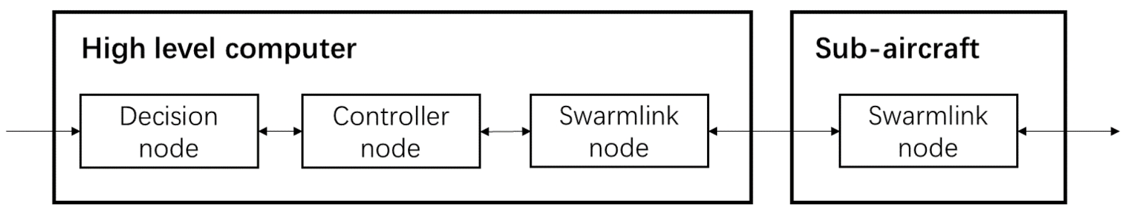
  • Unlike existing systems, we develop the hardware and the software of the system based on the CAN bus. Compared to existing work that relies on wireless communications, the CAN bus has low-latency communications, does not rely on external devices, and supports an expansion of the number and placement of the multiple sub-aircraft in an AVA.
  • Real-world experiments with three sub-aircraft were conducted. These illustrated the expandability of the system and the feasibility of the proposed methodology.
This paper consists of five sections. The dynamics modeling of a kind of AVA composed of multiple MAVs is investigated in Section 2. In Section 3, an example controller, a geometric TLC for the AVA system, is designed and validated. In Section 4, the detailed implementation of a real-world AVA prototype and the real-world experimental results are presented. Our conclusions are given in Section 5.

2. Dynamics Modeling and Controller Design Criteria

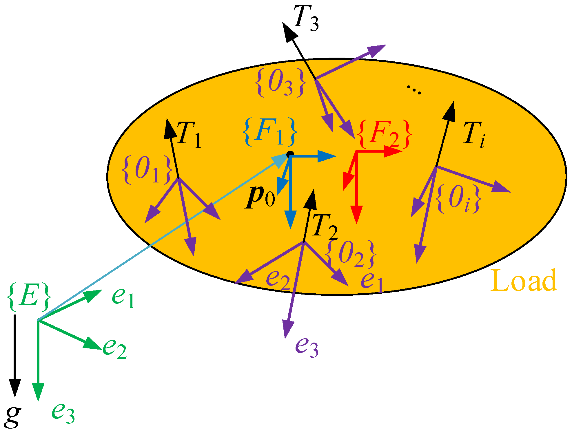
2.1. Modeling of an AVA

The AVA considered in this work is an assembly of multiple sub-aircraft. These provide the thrust for moving the entire assembly. Figure 1 depicts the configuration of the AVA. Figure 2 is a prototype. The payload platform is connected to the multiple sub-aircraft via spherical pairs. It is assumed that the center of mass (COM) of each sub-aircraft coincides with the center of the spherical pairs. The payload platform could have grippers, end effectors, etc.
To study the dynamics of the AVA composed of n sub-aircraft, we first define the coordinate frames of the system. The world frame is expressed by { E } , whose z-axis coincides with the direction of gravity. We attach a frame { F 1 } to the entire system. The origin of { F 1 } is the COM of the entire AVA. We also define a frame { F 2 } attached to the load. The origin of { F 2 } is the COM of the load. Note that { F 1 } and { F 2 } are parallel and reflect the orientation of the load but have different origins. We will show later that both { F 1 } and { F 2 } are necessary for the model. To each sub-aircraft i, we attach a body-fixed frame { O i } , i = 1 , 2 , , n . The dynamics of the entire system can, thus, be modeled via the Newton–Euler method as [14]:
M V ˙ 0 + C V 0 + G = R 0 0 0 I u 0 + d 0 ,
where V 0 : = ( v 0 , ω 0 ) R 6 is the velocity of the COM of the entire AVA, v 0 R 3 is the linear velocity expressed in frame { E } , ω 0 R 3 is the angular velocity expressed in frame { F 1 } , M R 6 × 6 , C R 6 × 6 , and G R 6 are the mass term, Coriolis term, and the gravity term, respectively, R 0 S O ( 3 ) is the rotation matrix for the attitude of the load, and I is the identity matrix. u 0 = ( F 0 T , τ 0 T ) T R 6 is the equivalent wrench generated by the multiple sub-aircraft acting on the load expressed in { F 1 } , and d 0 R 6 is the bounded uncertainty, which encompasses the unmodeled dynamics, the disturbance, and the modeling error. Expressions for the Coriolis term, mass term, and the gravity term can be obtained as follows:
M = m t 0 0 M t , C = 0 0 0 ( M t ω 0 ) ^ , G = m t g e 3 0 ,
with
m t = i = 0 n m i and M t = M 0 i = 1 n m i h ^ i ( h ^ i h ^ c ) ,
where m i is the mass of the ith sub-aircraft, m 0 is the mass of the load, M 0 is the inertia tensor of the load in the frame { F 2 } , g is the acceleration due to gravity, h i R 3 is the position of the ith sub-aircraft in { F 2 } , h c R 3 is the position of the COM of the AVA in the frame { F 2 } , and e 3 = ( 0 , 0 , 1 ) T . Given a vector a = ( a 1 , a 2 , a 3 ) T R 3 , the hat map a ^ is defined by
a ^ = 0 a 3 a 2 a 3 0 a 1 a 2 a 1 0 .
We assume that d 0 is bounded by
d 0 b 0 ,
where b 0 is a positive constant.
The translational and rotational kinematics of the entire AVA is expressed by
p ˙ 0 = v 0 , R ˙ 0 = R 0 ω ^ 0 ,
where p 0 R 3 denotes the position of the COM of the AVA.
The attitude of each sub-aircraft evolves according to the following equation:
R ˙ i = R i ω ^ i , ω ˙ i = M i 1 ( τ i ω ^ i M i ω i ) + d i ,
where R i S O ( 3 ) and ω i R 3 represent the rotation matrix and the angular velocity of the ith sub-aircraft, i = 1 , 2 , , n , respectively. τ i R 3 and d i R 3 are the input torque and uncertainties for the ith vehicle. We assume that the input τ i and disturbance d i are all bounded. The upper bound of d i is
d i b i .
where b i is a positive constant.
Besides the torque, the ith sub-aircraft is actuated by a thrust T i R . The direction of this thrust is constant for each sub-aircraft and coincides with R i e 3 . Therefore, the thrust vector expressed in the coordinate frame { F 1 } generated by sub-aircraft i is expressed by:
Y i = R 0 T R i e 3 T i .
The equivalent input wrench in (1) can then be expressed as:
u 0 = I I I l ^ 1 l ^ 2 l ^ n Y 1 Y 2 Y n : = N Y ,
where l i = w i w c for i = 1 , 2 , , n .
Thus, a model of the dynamics of the AVA has been built. The EOM of the entire AVA comprises (1)–(3). According to the EOM, the state of the AVA can be defined as:
x : = ( P 0 , V 0 , R i , ω i ) S E ( 3 ) × R 6 × S O ( 3 ) × R 3 × S O ( 3 ) × R 3 .
We can now define the state expressing the motion of the load as y = ( p 0 , R 0 , V 0 ) S E ( 3 ) × R 6 .
Remark 1.
The dynamics of each sub-aircraft are independent of the dynamics of the overall payload system. This is different from the dynamics of most aerial transportation systems, which rely on cables [19]. For an aerial transportation system with cables, the dynamics of each sub-aircraft is coupled with the dynamics of the payload platform. In contrast, the entire dynamics of the AVA can be expressed by two subsystems: a slowly varying system expressed by (1) and (2) and a fast time-varying system expressed by (3). It is easy to adapt a flight controller for a rigid aircraft to our AVA system, regardless of the number and placement of the sub-aircraft in the AVA.
Remark 2.
The disturbance includes the disturbance of the payload platform ( d 0 in Equation (1)) and the disturbance of each sub-aircraft ( d i in Equation (3)). In the model, the disturbance does not include the system states. Note that in (1) and (3), the state and the disturbance are different. It is reasonable to assume that such disturbances are bounded, as seen in the literature published by the aerial robotics community [20,21,22]. This assumption that the external disturbances are bounded can generally be satisfied in practical applications.

2.2. Adapting an Exponentially Stable Flight Controller

From the dynamics of the AVA system, it can be seen that the slowly varying system resembles the dynamics of a fully actuated rigid body, which can be expressed by the following equations:
p ¯ ˙ = v ¯ , R ¯ ˙ = R ¯ ω ¯ ^ , M V ¯ ˙ + C V ¯ + G = u ¯ ,
where p ¯ R 3 and R ¯ S O ( 3 ) are the position and rotation matrices of the rigid body, respectively, V ¯ = ( v ¯ , ω ¯ ) T , where v ¯ R 3 and ω ¯ R 3 are the linear velocity and angular velocity of the rigid body, and M R 6 × 6 , C R 6 × 6 , and G R 6 are the mass matrix, Coriolis matrix, and gravity term, respectively. Additionally, u ¯ = ( F ¯ , τ ¯ ) R 6 , where F ¯ and τ ¯ are the input force and torque of the rigid body. We define the state as z = ( p ¯ , v ¯ , R ¯ , ω ¯ ) .
An existing position and attitude controller of a rigid body can, therefore, be adapted for an AVA. Suppose that there is a controller that ensures that the translational and rotational error of a rigid body (6) is exponentially stable at the origin. We define the tracking error of the exponentially stable rigid body as z ˜ . According to the converse theorem of exponential stability, for an exponentially stable system there exists a continuously differentiable function V : [ 0 × ] × D 0 ( t , z ˜ ) V R such that V satisfies the following:
c 1 z ˜ 2 V c 2 z ˜ 2 , V ˙ c 3 z ˜ 2 , V z ˜ c 4 z ˜ ,
for some positive constants c 1 , c 2 , c 3 , and c 4 .
From the similarity between the fully actuated rigid body and the AVA system, a controller for a fully actuated rigid body (6) can be adapted and used as the controller for the slowly varying system of the AVA (1). We disregard the disturbance and suppose that the sub-aircraft have no attitude tracking error. We denote the state tracking error by y ˜ . The same Lyapunov function V : [ 0 × ] × D 0 ( t , y ˜ ) V R also satisfies the following:
c 1 y ˜ 2 V c 2 y ˜ 2 , V ˙ c 3 y ˜ 2 , V y ˜ c 4 y ˜ .
If the virtual control of the AVA defined by the exponential stable controller is defined by τ 0 , d and F 0 , d , then the commanded thrust vector of each sub-aircraft can be calculated by inverting (5) as:
γ = N + R 0 0 0 I 1 F d τ d ,
where N 1 is the pseudo-inverse of the allocation matrix N.
Next, we consider the attitude error for each sub-aircraft. It is supposed that the attitude controller of each sub-aircraft is stable and that the disturbance is bounded. Then, from the regular perturbation theorem [23], we conclude that the attitude tracking error of each sub-aircraft is bounded. We can express the boundedness of the attitude tracking error of each sub-aircraft by
R i R ¯ i Δ R ,
where the positive constant Δ R determines the boundedness. As there is a difference between the actual and commanded thrust vectors due to the attitude tracking error, the boundedness of the difference is then expressed by
Υ i Υ ¯ i = R 0 T R i T i e 3 R 0 T R ¯ i T i e 3 T i R i R ¯ i T m Δ R ,
where T m is the maximum thrust magnitude that each sub-aircraft can provide.
From (5) and (11), we obtain that the actual and desired forces exerted on the payload platform satisfy:
F 0 F 0 , d = i ( Υ i Υ ¯ i ) Υ i Υ ¯ i T m Δ R : = L F .
Similarly, we can also obtain that the desired equivalent torque τ 0 , d and actual equivalent torque τ 0 satisfy:
τ 0 τ 0 , d = l ^ i ( Υ i Υ ¯ i ) l ^ i ( Υ i Υ ¯ i ) l i Υ i Υ ¯ i : = L τ .
Hence, for the AVA ((1)–(3)), we suppose that the equivalent force and torque acting on the payload platform are defined by (5) and that the attitude tracking error of each sub-aircraft satisfies (10). We can thus conclude that the difference between u 0 = ( F 0 , τ 0 ) and u 0 , d = ( F 0 , d , τ 0 , d ) is bounded.
We can now conclude that the attitude error for each sub-aircraft disturbs the slowly varying system:
M V ˙ 0 + C V 0 + G = R 0 0 0 I u 0 , d + d 0 * ,
where the upper bound of d 0 * is determined by
d 0 * d 0 + L F 2 + L τ 2 = b 0 + L F 2 + L τ 2 .
We again consider the AVA system, (1)–(3). Based on the attitude tracking error of each sub-aircraft, we have
V ˙ = c 3 y ˜ 2 + V y ˜ M 1 d 0 * .
The thrust provided by the aerial vehicle is also bounded. It can be expressed as T b 3 , where b 3 is a positive constant. Then, we have
V ˙ c 3 y ˜ 2 + V y ˜ 1 λ m ( M ) d 0 * c 3 y ˜ 2 + c 4 L F 2 + L τ 2 λ m ( M ) y ˜ ( 1 θ ) c 3 y ˜ 2 θ c 3 y ˜ 2 + c 4 L F 2 + L τ 2 λ m ( M ) y ˜ ,
where θ < 1 is a positive constant.
We define
c 5 = c 4 b 0 + L F 2 + L τ 2 λ m ( M ) .
Then, from (12), (13) and (16), we can conclude that y ˜ converges to the region
y ˜ : y ˜ c 2 c 5 c 1 θ c 3 ,
in finite time. Therefore, it is possible to adapt an existing exponentially stable position or attitude controller for an AVA system.

3. Example Design of a Geometric Controller

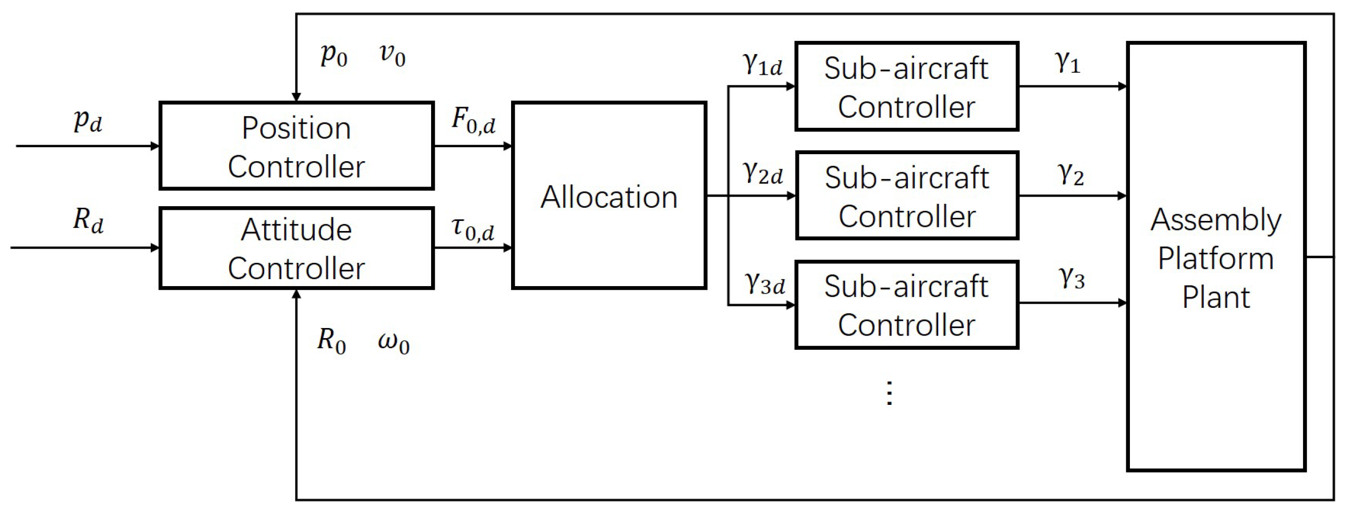
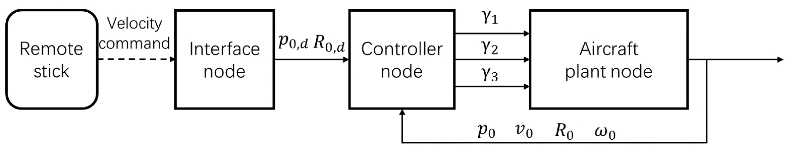
3.1. Overall Controller Architecture

As the dynamics model shows, the rotational motion of each sub-aircraft is not affected by the motion of the load. Therefore, in the controller design, the rotational motion of each aircraft is treated as a fast varying system, whereas the overall motion of the AVA is regarded as a slowly varying system. With these definitions, the overall controller has a hierarchical structure. The outer loop controls the load, whereas the inner loop controls the attitude of each sub-aircraft. As attitude control for small sub-aircraft is mature enough, some existing attitude controllers can be directly adopted for the sub-aircraft.
For the six-DOF AVA, the overall controller is composed of an independent position controller and an attitude controller. The output of the position controller is the force vector F 0 , and the output of the attitude controller is the torque vector τ 0 . The overall control architecture is shown in Figure 3. In the outer loop, the force and torque generated by the position control and attitude control need to be mapped to the thrust vector of the sub-aircraft, which is then tracked by the attitude controller of the sub-aircraft.

3.2. Payload Controller Design

The attitude of the slowly varying system evolves on S O ( 3 ) . In this example, we design the attitude sub-controller using TLC [24,25]. To avoid the traditional problems of an attitude control system expressed in local coordinates, the attitude tracking error is defined directly from the rotation matrix. TLC is combined with an open-loop pseudo-inverse module and a feedback stabilization regulator. The former enhances the dynamic behavior of the system, whereas the latter ensures the stability of the closed-loop system. In TLC, the system is linearized along the nominal trajectory, based on which the gains in the feedback regulator are designed from the desired closed-loop system. The design principle of TLC aligns with gain schedule schemes. Therefore, it is suitable for aircraft control.

3.2.1. Outer Loop of Payload Attitude Control

The kinematic equations of the slowly varying system evolve on S O ( 3 ) . These are actually similar to the kinematic equation for the rotational motion of rigid bodies. The dynamic inversion of the outer loop of the attitude controller can be obtained from the kinematic equation as:
ω ¯ 0 = R 0 T R 0 , d ( R 0 , d T R ˙ 0 , d ) ,
where ∨ denotes the vee map (the inverse of the hat map) and R 0 , d is the desired rotation matrix.
To design the feedback control, the attitude tracking error is augmented as:
e Σ = e R T , e R T T ,
where the tracking error e R is defined as
e R ( t ) = 1 2 ( R 0 , d T ( t ) R 0 ( t ) R 0 T ( t ) R 0 , d ( t ) ) .
According to the results in [25], we can derive the linearized tracking error dynamics on S O ( 3 ) and then obtain the linearized tracking error dynamics expressed in terms of the augmented tracking error e Σ as follows:
e ˙ Σ = ω ¯ 0 0 0 0 e Σ + I 3 0 0 I n ω ˜ 0 = A 1 e Σ + B 1 ω ˜ 0 .
We apply the following control law for the outer loop regulator:
ω ˜ 0 = K 1 e Σ ,
where the control gain matrix K 1 = K I 1 | K P 1 is designed from the linearized Equation (18) using the PD spectral theorem [25].
Finally, the commanded angular velocity of the slowly varying system is
ω 0 , d = ω ¯ 0 + ω ˜ 0 ,
which is then input to the inner loop of the payload attitude controller.

3.2.2. Inner Loop of Payload Attitude Control

The inner loop of the attitude control is designed in a similar manner. The inner pseudo-inverse is obtained as follows:
τ ¯ 0 = M t ω ˙ 0 , d + ω ^ 0 , d M t ω 0 , d .
The feedback stabilization regulator is
τ ˜ 0 = K 2 E ω ,
where E ω = ω 0 ω 0 , d . The control gain K 2 is also designed using the PD spectral theorem. It is a function of the desired closed-loop frequency and damping ratio, respectively.
The commanded torque is then
τ 0 , d = τ ¯ 0 + τ ˜ 0 .

3.2.3. Position Control of the Payload Platform

The EOM for the translational motion of the payload platform is a linear system. The translational tracking error dynamics can, therefore, be expressed by:
e ˙ l = 0 I 0 0 e l + 0 I R 0 F 0 , d m t + g e 3 p ¨ 0 , d ,
where e l = ( e p , e ˙ p ) , and e p = p 0 p 0 , d is the position tracking error. Position control can, therefore, be easily designed as
F 0 , d = R 0 T ( K 3 e ˙ p K 4 e p + p ¨ 0 , d g e 3 ) m t ,
such that the closed-loop system becomes
e ˙ l = A c l p e l ,
where A c l p is a Hurwitz matrix.

3.2.4. Allocating the Wrench

The output of the controller for the slowly varying system is the 6D wrench u 0 , d = ( F 0 , d , τ 0 , d ) , which has to be mapped to the attitude and thrust commands of each sub-aircraft. The mapping is done by the allocation module. Note that the thrust and attitude of each sub-aircraft are bounded. However, it is difficult to realize bounded allocation. To reduce the computational burden, the allocation simply uses the pseudo-inverse of matrix N in the controller. The allocation mapping can, therefore, be written as:
Y ¯ = N + u 0 , d .
Then, the commanded thrust Y ¯ i can be converted to the thrust magnitude and commanded attitude of each aircraft as:
T i = Y ¯ i , R ¯ i e 3 = Y ¯ i T i ,
where the desired z-axis of the body frame R ¯ i e 3 can be transformed to the full attitude, which is then tracked for each sub-aircraft by its attitude controller.
Remark 3.
Previous work proposed a method for optimal control allocation that takes into account the feasibility of the wrench on the platform [14]. Unlike that work, we directly apply the pseudo-inverse in control allocation to reduce the computational burden. As will be shown later in the simulation and experiments, this is feasible. However, such an allocation approach does not consider the control boundedness, which is beyond the scope of this paper.
Remark 4.
To determine fully the commanded attitude of each sub-aircraft from (27), researchers typically uses the yaw angle (or one of the other x- and y-axes). The detailed expression is omitted here for brevity.

3.3. Stability Analysis

The stability analysis of the entire system is based on the results in Section 2.2. First, we ignore the disturbance and the attitude tracking error of the sub-aircraft. An exponentially stable closed-loop system without disturbance is obtained. The disturbance is then considered. We conclude that the overall system is ultimately bounded with disturbances.
Proposition 1.
Consider the rotational part of (1) without disturbance. Suppose τ 0 is based on (20) and (23).
1. 
There exists a positive constant r ω such that for all E ω < r ω , the closed-loop tracking error E ω is exponentially stable at the origin E ω = 0 .
2. 
Moreover, suppose that the initial attitude error satisfies tr ( I R 0 , d T R 0 ) / 2 < 2 . Then, if the control gains are selected appropriately, the closed-loop attitude tracking error is exponentially stable at e R = 0 and e ω = 0 , where e ω = ω 0 ( R 0 , d T R ˙ 0 , d ) .
A proof of this proposition can be found in the authors’ previous work [25].
Remark 5.
The basin of attraction is defined by the set of the initial angular velocities { E ω : E ω < r ω } and the set of initial attitude tracking errors { R 0 : tr ( I R 0 , d T R 0 ) / 2 < 2 } . The former indicates that the initial tracking error should be bounded. This is also in line with the physical conditions. The latter almost covers all of S O ( 3 ) except for a two-dimensional surface R 0 , d T R 0 = ± exp ( π s ) , s S 2 , from the three-dimensional S O ( 3 ) . An illustration of the basin of attraction of initial attitude error can be found in Figure 5 later.
Proposition 2.
Consider the translational part of (1) without disturbance. Suppose that F 0 is designed from (25). If the control parameters are appropriately selected such that A c l p is a Hurwitz matrix, then the closed-loop tracking error ( e l , e ˙ l ) is exponentially stable at the origin.
Proof. 
The closed-loop system of (24) is a linear system. The exponential stability is trivial if A c l p is Hurwitz.  □
Theorem 1.
Consider the dynamic equations of the AVA, namely, (1)–(3). Suppose that τ 0 is designed from (20) and (23) and that F 0 is designed from (25).
1. 
There exists a positive constant r ω such that for all E ω < r ω , the closed-loop tracking error E ω converges to the region containing the origin in finite time.
2. 
Moreover, suppose that the initial attitude error satisfies tr ( I R 0 , d T R 0 ) / 2 < 2 . If the control gains are selected appropriately, then the closed-loop attitude tracking error converges to the region containing the origin in finite time.
3. 
If the control parameters are selected appropriately such that A c l p is a Hurwitz matrix, then the closed-loop tracking error ( e l , e ˙ l ) converges to the region containing the origin in finite time.
Proof. 
From Proposition 1, it can be seen that we can construct the position and attitude control such that the rigid body system (6) under the control of (20), (23) and (25) is exponentially stable. Then, following the procedures described by (7)–(16), we have proved the ultimate boundedness of a closed-loop AVA.  □
Remark 6.
The EOM of the entire system AVA is continuous, which is, of course, Lipschitz continuous. Therefore, the solution of the differential equation defined in (1)–(3) exists and is unique. The controller determined by (20), (23), and (25) and the allocation (26) exists and is unique. Therefore, the existence and uniqueness of the solution of the overall closed-loop system is guaranteed.

4. Real-World System Implementation

4.1. Configuration of the Prototype

We designed a prototype consisting of three sub-aircraft arranged in a star shape. The three sub-aircraft were connected to the payload platform via passive spherical joints, one at the COM of each sub-aircraft. Each sub-aircraft rotated freely around the center of a spherical joint and provides thrust for the AVA. It can be proved that the six dimensions of the pose of this prototype can be changed simultaneously [19]. Figure 2 shows the prototype. The main structural components were made of carbon fiber. The rotational range of the ball hinges used in the prototype was φ = 55 .

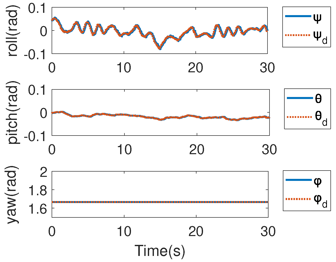
4.2. Real-Time Simulation of the Software

Before implementing a real-world AVA prototype, it was simulated on a Ubuntu 18.04/ROS software environment to verify the entire software implementation. Figure 4 depicts the overall simulation system. The ROS node used to simulate the plant of the AVA was implemented from the EOM, namely (1)–(3). In the simulation, we used a remote control stick to send commands. The interface software was also integrated into the simulation system as ROS nodes. The simulation also included disturbances.
The simulated tracking of the position and attitude of the AVA is shown in Figure 5. There was an initial position error and an initial attitude error. The initial error for the yaw angle of the payload platform was almost 180°, which means that the attitude error was almost a maximum. As shown in the figure, the time-varying reference attitude trajectory was independent of the reference position trajectory. The controller simultaneously tracked the reference position and attitude of the AVA. The attitude of the payload platform was adjusted when approaching the target position from the initial position.
Thus, this real-time simulation demonstrated the feasibility, correctness, and completeness of the controller nodes and the overall software architecture. These can serve as the basis for a real-world prototype.

4.3. Development and Implementation of a Prototype

Based on the design and simulation results presented above, the software and hardware of a real-world prototype were developed. The payload platform of the AVA was integrated with avionics equipment, including a high-level onboard computer, remote control receiver, GPS receiver, central flight management unit (FMU), and radio. The central FMU needs to be fixed as near as possible to the COM of the payload platform. The FMU receives commands sent by the remote stick, calculates the feedback pose and velocity through sensor fusion, and then sends these values to the high-level onboard computer via a USB serial port. The radio communicates with a ground station, which is mainly used for monitoring and recording flight data.
We developed the sub-aircraft for the prototype AVA. Each sub-aircraft contains a full set of electronic devices. Therefore, the sub-aircraft can fly when connected together in an assembly or separately when not connected together. The flight controller of each sub-aircraft was the PX4 autopilot. Figure 6 shows a single sub-aircraft flying alone.
Figure 7 shows the architecture of the hardware system developed for the AVA prototype. Rather than using wireless communication, the computer on the payload platform and the autopilot of each sub-aircraft were connected by a CAN bus to increase the reliability and real-time performance. This also enhanced the expandability of the system.
Figure 8 shows the software system developed for the AVA prototype. It was based on the ROS framework. The Swarmlink nodes handled communications among the high-level computer and multiple sub-aircraft. The Decision and Controller nodes were the planning and control modules. The Controller node was based on the controller proposed in this paper.
The relevant physical parameters of the developed AVA prototype are summarized in Table 1. For the three-quadrotor assembly, the weight of the full assembly is almost 4 times the weight of each sub-aircraft. Therefore, the payload capacity is not 3 times the payload of each individual quadrotor, mainly because of the components used to connect the quadrotors. However, the proposed AVA is a flexible system, which means it is possible to adjust the payload capacity with different combinations of quadrotors. Note that the connecting parts may induce payload loss. It is possible to increase the payload ability of the entire AVA with an optimal design, which is the subject of our future research.

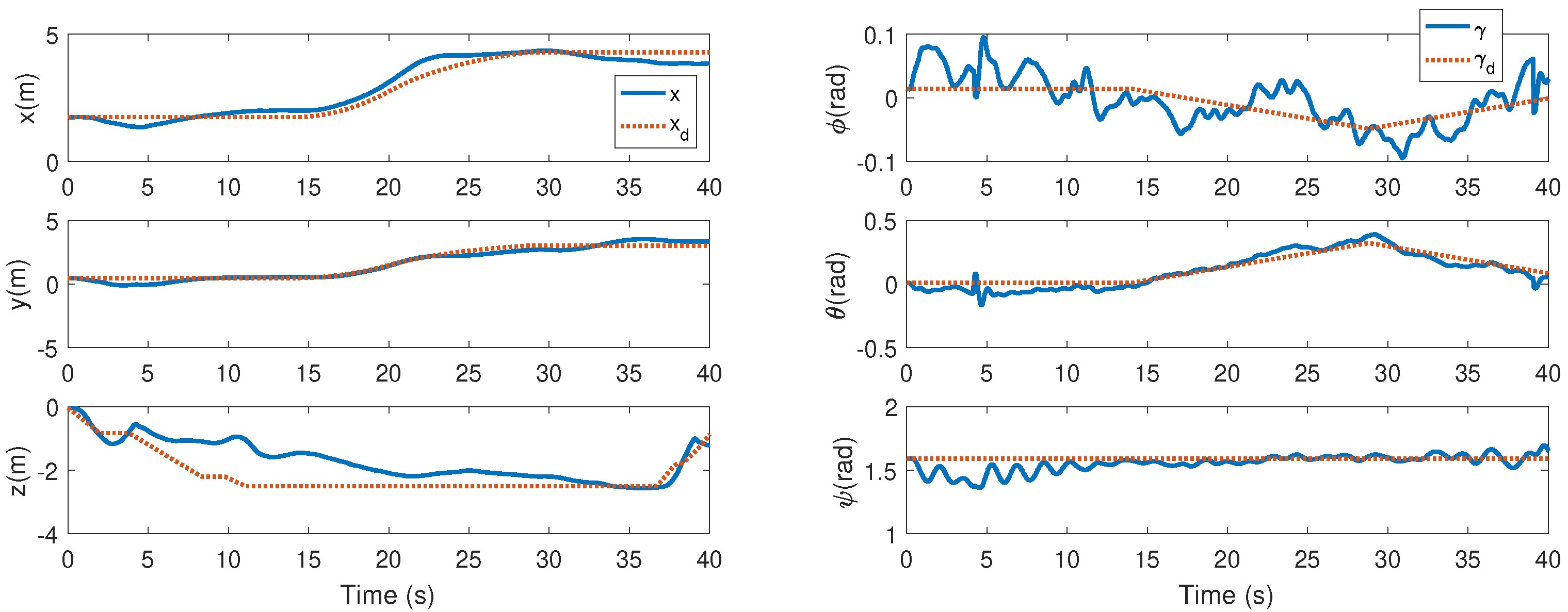
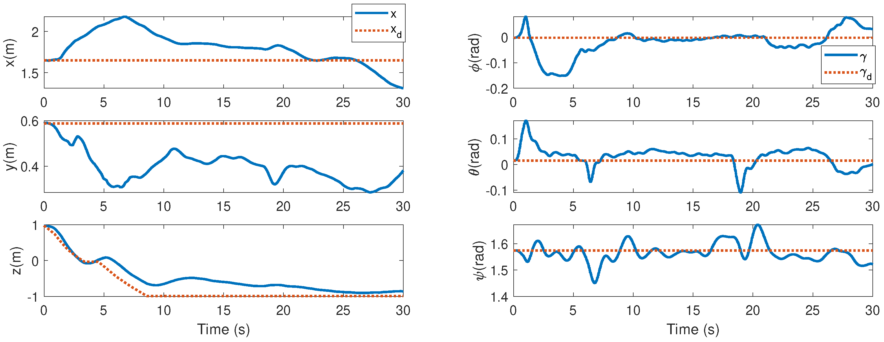
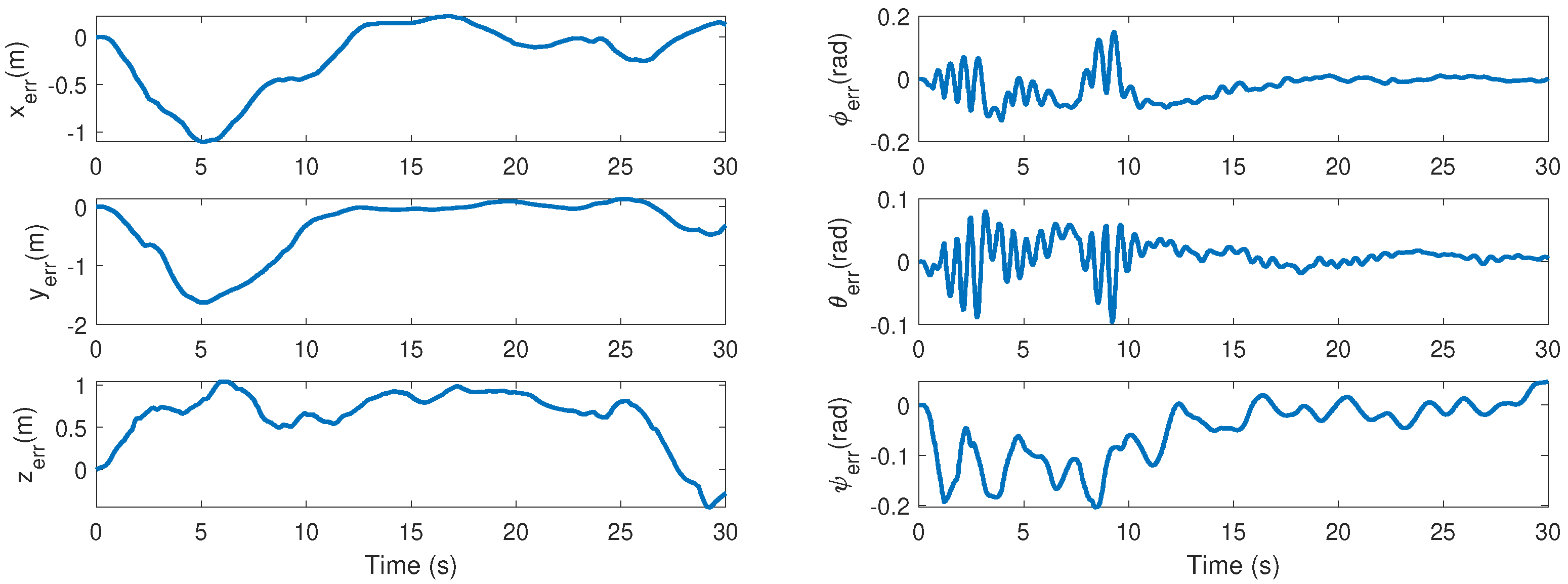
4.4. Real-World Experimental Results

Flight tests of the AVA prototype composed of three sub-aircraft was conducted. The test scenario is illustrated in the Video S1 in the Supplementary Material, which shows the simultaneous 6D pose tracking.
Figure 9 shows a flight test of the AVA without payload. Figure 10 shows the results of the AVA with an additional payload of 2.5 kg. In these two figures, it is seen that the AVA is able to track the independent 6D pose trajectory simultaneously. It does not need the position trajectory and the attitude trajectory to satisfy dynamic constraints. This cannot be achieved by an underactuated aircraft.
Since the test was conducted outdoors, the prototype was disturbed by wind. As Figure 9 shows, the maximum tracking errors of the position were around 0.4 m in the horizontal x-direction and y-direction. Considering that an AVA is a complex system, and there exist GPS drifting errors and wind in outdoor environment, these errors are all within a reasonable range.
It is also noted that the geometric control can adapt to different payloads from Figure 9 and Figure 10.
Remark 7.
The geometric controller has several parameters. Actually, in control law (22) and control law (24), there are gains before the proportional term and the integral term. Tuning the parameters is similar to tuning a PID controller. By tuning the control parameters, the upper bound of the tracking error can be adjusted.
Figure 11 shows an example of the attitude tracking of one sub-aircraft. The PX4 flight controller was used to track the commanded attitude. Note that we did not need to tune the PX4 for the flight tests. For each aircraft, the PX4 controller was set up in the same way for individual flights and for the flight by the assembly. This is also beneficial for the expandability of the AVA.
The hardware and software system worked well throughout the flight test. These real-world tests demonstrated that with the developed controller, the AVA can track the six dimensions for the independent position and attitude trajectories simultaneously, without requiring the position and attitude trajectories to meet dynamic constraints. The stability of the controller proposed in this paper was also verified in the tests.

4.5. Comparison with MPC-Based Control Scheme

Model predictive control (MPC) was also implemented in the prototype. The geometric control scheme is compared with the model predictive control-based control scheme. The results of the AVA in hovering under MPC-based scheme are shown in Figure 12. The results of the AVA under the geometric control scheme is shown in Figure 13. The tracking error of the position and attitude are shown in Figure 14 and Figure 15, respectively. Due to the modeling uncertainties in the system, the tracking error of the AVA under the MPC-based scheme is relatively large, although it can also force the tracking error into a region containing the origin.
Remark 8.
The probability of autopilot failure increases as the number of autopilots is increased in the AVA system. If the failure probability of one autopilot is P ( f 1 ) , then the failure probability of three autopilots is P ( f 2 ) = 1 ( 1 P ( f 1 ) ) 3 . We plot Figure 16 to show the relationship between P ( f 2 ) and P ( f 1 ) , it is seen that when P ( f 1 ) = 0.01 , P ( f 2 ) = 0.0297 , and when P ( f 1 ) = 0.02 , P ( f 2 ) = 0.0588 . On one hand, we need to decrease the failure probability of the autopilot as much as possible. If P ( f 1 ) is small enough, then P ( f 2 ) is possible to be kept in an acceptable range. On the other hand, since an AVA is a complex system, the reliability of complex system will of course decrease. How to increase the reliability of the entire system is an interesting problem and could be investigated in the future.
Remark 9.
The PX4 autopilot of each individual quadrotor in the three-quadrotor prototype was tuned so that the attitude tracking of a single quadrotor was good enough. Actually, we used F450 quadrotors, and the PX4 autopilot has a configuration with fine-tuned parameters for this type of quadrotor. However, in tuning the AVA, the PX4 autopilot did not need to be tuned anymore. Only the parameters in the outer loop controller for the slowly varying system were tuned.
Remark 10.
Real-world systems always include sensor noise. As the geometric controller can be implemented in the real-world prototype, it is seen that that the controller is effective in the presence of sensor noise.

5. Conclusions

In this paper, a controller was designed and a prototype implemented for an AVA, which took into account its expandability. The controller was designed for the non-Euclidean configuration space of the AVA. An existing flight controller for sub-aircraft was used. Data communication among the onboard controller and the autopilots for the sub-aircraft was via a real-time bus, which ensured the reliability and extendability of the system. Based on the partitioned dynamics of the AVA, it is seen that the slowly varying system can be designed from the existing exponentially stable controller. Such a design criteria was used to design an AVA’s geometric controller, whose almost global stability was demonstrated in terms of the tracking error of each sub-aircraft. This stability increases the maneuverability of the AVA. Furthermore, a real-world prototype was built. The proposed design and implementation were verified in flight tests. Because expandability was one of the design criteria for the controller and prototype, an AVA with multiple aerial vehicles can easily be constructed for other configurations using the approach presented in this paper.

Supplementary Materials

The following supporting information can be downloaded at: https://www.mdpi.com/article/10.3390/drones6100272/s1, Video S1: Video of the AVA under control.

Author Contributions

Simulation, C.S. and K.W.; formal analysis, C.S. and Y.Y.; experiments, K.W. and C.S.; writing—original draft, C.S.; supervision, Y.Y. All authors have read and agreed to the published version of the manuscript.

Funding

Funding was received from the National Key R. D. Program of China and the State Key Laboratory of Robotics and Systems (HIT).

Conflicts of Interest

The authors declare no conflict of interest.

References

  1. Kim, S.J.; Lee, D.Y.; Jung, G.P.; Cho, K.J. An origami-inspired, self-locking robotic arm that can be folded flat. Sci. Robot. 2018, 3, eaar2915. [Google Scholar] [CrossRef]
  2. Estrada, M.A.; Mintchev, S.; Christensen, D.L.; Cutkosky, M.R.; Floreano, D. Forceful manipulation with micro air vehicles. Sci. Robot. 2018, 3, eaau6903. [Google Scholar] [CrossRef] [PubMed]
  3. Ding, X.; Guo, P.; Xu, K.; Yu, Y. A review of aerial manipulation of small-scale rotorcraft unmanned robotic systems. Chin. J. Aeronaut. 2019, 32, 200–214. [Google Scholar] [CrossRef]
  4. Ruggiero, F.; Lippiello, V.; Ollero, A. Aerial manipulation: A literature review. IEEE Robot. Autom. Lett. 2018, 3, 1957–1964. [Google Scholar] [CrossRef]
  5. Meng, X.; He, Y.; Han, J. Survey on aerial manipulator: System, modeling, and control. Robotica 2020, 38, 1288–1317. [Google Scholar] [CrossRef]
  6. Yu, Y.; Ding, X. A Global Tracking Controller for Underactuated Aerial Vehicles: Design, Analysis, and Experimental Tests on Quadrotor. IEEE/ASME Trans. Mechatronics 2016, 21, 2499–2511. [Google Scholar] [CrossRef]
  7. Jimenez-Cano, A.E.; Sanchez-Cuevas, P.J.; Grau, P.; Ollero, A.; Heredia, G. Contact-based bridge inspection multirotors: Design, modeling, and control considering the ceiling effect. IEEE Robot. Autom. Lett. 2019, 4, 3561–3568. [Google Scholar] [CrossRef]
  8. Orsag, M.; Korpela, C.; Bogdan, S.; Oh, P. Dexterous aerial robots—Mobile manipulation using unmanned aerial systems. IEEE Trans. Robot. 2017, 33, 1453–1466. [Google Scholar] [CrossRef]
  9. Zhang, G.; He, Y.; Dai, B.; Gu, F.; Yang, L.; Han, J.; Liu, G.; Qi, J. Grasp a moving target from the air: System & control of an aerial manipulator. In Proceedings of the 2018 IEEE International Conference on Robotics and Automation (ICRA), Brisbane, Australia, 21–25 May 2018; pp. 1681–1687. [Google Scholar]
  10. Lippiello, V.; Fontanelli, G.A.; Ruggiero, F. Image-based visual-impedance control of a dual-arm aerial manipulator. IEEE Robot. Autom. Lett. 2018, 3, 1856–1863. [Google Scholar] [CrossRef]
  11. Yu, Y.; Li, P.; Gong, P. Finite-time geometric control for underactuated aerial manipulators with unknown disturbances. Int. J. Robust Nonlinear Control. 2020, 30, 5040–5061. [Google Scholar] [CrossRef]
  12. Ollero, A.; Tognon, M.; Suarez, A.; Lee, D.; Franchi, A. Past, Present, and Future of Aerial Robotic Manipulators. IEEE Trans. Robot. 2022, 38, 626–645. [Google Scholar] [CrossRef]
  13. Yu, Y.; Lippiello, V. 6D Pose Task Trajectory Tracking for a Class of 3D Aerial Manipulator From Differential Flatness. IEEE Access 2019, 7, 52257–52265. [Google Scholar] [CrossRef]
  14. Nguyen, H.; Park, S.; Park, J.; Lee, D. A Novel Robotic Platform for Aerial Manipulation Using Quadrotors as Rotating Thrust Generators. IEEE Trans. Robot. 2018, 34, 353–369. [Google Scholar] [CrossRef]
  15. Petitti, A.; Sanalitro, D.; Tognon, M.; Milella, A.; Cortés, J.; Franchi, A. Inertial Estimation and Energy-Efficient Control of a Cable-suspended Load with a Team of UAVs. In Proceedings of the 2020 International Conference on Unmanned Aircraft Systems (ICUAS), Athens, Greece, 1–4 September 2020; pp. 158–165. [Google Scholar] [CrossRef]
  16. Yang, H.; Park, S.; Lee, J.; Ahn, J.; Son, D.; Lee, D. LASDRA: Large-Size Aerial Skeleton System with Distributed Rotor Actuation. In Proceedings of the 2018 IEEE International Conference on Robotics and Automation (ICRA), Brisbane, Australia, 21–25 May 2018; pp. 7017–7023. [Google Scholar] [CrossRef]
  17. Hamandi, M.; Usai, F.; Sable, Q.; Staub, N.; Tognon, M.; Franchi, A. Design of multirotor aerial vehicles: A taxonomy based on input allocation. Int. J. Robot. Res. 2021, 40, 1015–1044. [Google Scholar] [CrossRef]
  18. Yu, Y.; Wang, K.; Guo, R.; Lippiello, V.; Yi, X. A framework to design interaction control of aerial slung load systems: Transfer from existing flight control of under-actuated aerial vehicles. Int. J. Syst. Sci. 2021, 52, 2845–2857. [Google Scholar] [CrossRef]
  19. Lee, T. Geometric Control of Quadrotor UAVs Transporting a Cable-Suspended Rigid Body. IEEE Trans. Control. Syst. Technol. 2018, 26, 255–264. [Google Scholar] [CrossRef]
  20. Wei, L.; Chen, M.; Li, T. Disturbance-observer-based formation-containment control for UAVs via distributed adaptive event -triggered mechanisms. J. Frankl. Inst. 2021, 358, 5305–5333. [Google Scholar] [CrossRef]
  21. Shao, S.; Chen, M.; Hou, J.; Zhao, Q. Event-Triggered-Based Discrete-Time Neural Control for a Quadrotor UAV Using Disturbance Observer. IEEE/ASME Trans. Mechatronics 2021, 26, 689–699. [Google Scholar] [CrossRef]
  22. Xu, L.X.; Ma, H.J.; Guo, D.; Xie, A.H.; Song, D.L. Backstepping Sliding-Mode and Cascade Active Disturbance Rejection Control for a Quadrotor UAV. IEEE/ASME Trans. Mechatronics 2020, 25, 2743–2753. [Google Scholar] [CrossRef]
  23. Khalil, H.K. Nonlinear Systems; Prentice Hall: Hoboken, NJ, USA, 1991. [Google Scholar]
  24. Yu, Y.; Ding, X.; Zhu, J.J. Attitude tracking control of a quadrotor UAV in the exponential coordinates. J. Frankl.-Inst.-Eng. Appl. Math. 2013, 350, 2044–2068. [Google Scholar] [CrossRef]
  25. Yu, Y.; Ding, X. Trajectory linearization control on SO(3) with application to aerial manipulation. J. Frankl. Inst. 2018, 355, 7072–7097. [Google Scholar] [CrossRef]
Figure 1. Configuration of the aerial vehicle assembly (AVA). The center of mass (COM) of each sub-aircraft coincides with the center of a spherical joint. The thrust provided by each sub-aircraft is along the negative direction of R i e 3 . There is no cable between the payload platform and the spherical joints.
Drones 06 00272 g001
Figure 2. Example of an AVA prototype with three small quadrotors.
Drones 06 00272 g002
Figure 3. Overall controller architecture.
Drones 06 00272 g003
Figure 4. Simulation of an AVA with three quadrotors.
Drones 06 00272 g004
Figure 5. Simulation results. The initial attitude error was almost a maximum. A traditional controller relying on Euler angles cannot stabilize the system in such conditions. (a) Position tracking. (b) Attitude tracking.
Drones 06 00272 g005
Figure 6. Flight test of a single sub-aircraft.
Drones 06 00272 g006
Figure 7. Hardware architecture of the AVA. FMU: flight management unit, IMU: inertial measurement unit, RC: radio control.
Drones 06 00272 g007
Figure 8. Software architecture of the AVA.
Drones 06 00272 g008
Figure 9. The position tracking profile in a real-world test without additional payload. Note that the position trajectory is independent of the attitude trajectory. Such command is not possible to achieve by individual quadrotor aircraft.
Drones 06 00272 g009
Figure 10. The position tracking profile in real-world test with 2.5 kg additional payload. Note that the position trajectory is independent of the attitude trajectory. Such command is not possible to achieve by individual quadrotor aircraft.
Drones 06 00272 g010
Figure 11. Attitude tracking of one sub-aircraft with the PX4 flight controller in one test.
Drones 06 00272 g011
Figure 12. The position and attitude tracking profile of the AVA under MPC-based scheme.
Drones 06 00272 g012
Figure 13. The position and attitude tracking profile of the AVA under the geometric control scheme.
Drones 06 00272 g013
Figure 14. The position and attitude tracking error of the AVA under MPC-based scheme.
Drones 06 00272 g014
Figure 15. The position and attitude tracking error of the AVA under the geometric control scheme.
Drones 06 00272 g015
Figure 16. P ( f 2 ) (the failure probability of three autopilot) vs. P ( f 1 ) (the failure probability of one autopilot).
Drones 06 00272 g016
Table 1. Physical parameters of the AVA prototype.
AircraftMassPayload CapacityComputing Unit
Sub-aircraft1.58 kg1.50  kgPX4 FMUv5
AVA6.24 kg3.02 kgNvidia nano computer
Publisher’s Note: MDPI stays neutral with regard to jurisdictional claims in published maps and institutional affiliations.

