Abstract
This paper deals with the design of a guidance control system for a swarm of unmanned aerial systems flying at a given altitude, addressing flight formation requirements that can be formulated constraining the swarm to be on the nodes of a triangular mesh. Three decentralized guidance algorithms are presented. A classical fixed leader–follower scheme is compared with two alternative schemes: the former is based on the self-identification of one or more time-varying leaders; the latter is an algorithm without leaders. Several operational scenarios have been simulated involving swarms with obstacles and an increasing number of aircraft in order to prove the effectiveness of the proposed guidance schemes.
1. Introduction
In the last decade, research on civil unmanned aerial systems has been growing due to their great versatility and adaptability to several kinds of missions and lower operating costs as well. However, the use of a single Unmanned Aerial Vehicle (UAV) may be not effective for some missions, whereas the cooperation of more UAVs as a team allows more complex tasks to be accomplished, reducing time and/or space required to achieve the mission goals or to enhance the robustness of the overall missions [1,2,3].
Several advantages can be obtained with UAV formations. For instance, the components of a team can simultaneously collect information from multiple locations, thus reducing the time needed to acquire all the data necessary for decision-making, or they can take actions in multiple locations, reducing the reaction time. Another important feature is related to the complementarity of flight formation members; for example, the efficiency of the system can be improved by distributing different sensors on multiple UAVs, thus reducing payload and, in the case of redundancy, increasing at the same time the robustness of the whole system, no longer related to the reliability of a single aircraft. As the costs of a single aircraft exponentially increase with the take-off weight, the use of several smaller UAVs can also be effective in reducing production and operating costs [4,5]. Furthermore, smaller vehicles have a better capability to move in confined spaces and, by operating many of them, it is possible to survey a wider area than a single, larger aircraft, even if equipped with better sensors [6,7,8,9,10,11].
A real improvement can be achieved if all the aircraft can properly collaborate to accomplish the mission target by coordinating their tasks. Within this frame, an extensive research field focuses on the swarming behavior, or flocking, known in nature as the collective behavior of a large number of agents able to interact and share a common objective [12,13,14,15,16,17,18,19,20]. In particular, flocking is the ability of a group of autonomous agents (being aircraft or robots) to move like a swarm of birds or insects.
At this scope, consensus control algorithms guide each agent to find the agreement on a certain state. In the literature, the multi-agent formation stabilization problem is defined with the objective of designing a decentralized control law for a fleet of mobile robots used to stabilize an assigned formation shape. Another important problem is related to the determination of the right geometric shape, based on local measures as displacements, distances and bearings.
Two standard strategies for formation control using consensus are the most used: distance-based control and position-based control. In the distance-based control, each vehicle keeps an assigned distance from its adjacent robots. In this case, a rigid graph topology [21,22,23,24] is defined to describe the fleet network. In the displacement-based control, each robot follows the desired position as a deviation from a pre-defined formation center. However, all agents must know the formation center. Finally, the position-based formation strategy can be expensive, needing a plan and being less adaptive to changes in the environment, while its results are unnecessary if the position of each robot is not strictly required.
To reduce the information exchange and to improve the robustness of the control strategy, the displacement-based formation strategy has been extensively studied [25,26,27,28,29]. This method can also be considered consensus-based since the formation problem can be transformed into a consensus problem [27,30,31,32].
The classical model for swarm control is based on three heuristic rules [33]: cohesion, separation and alignment; however, several concepts of UAV formations can be operated. One concept considers a physical coupling between aircraft that are constrained in their flight. A typical example can be the transportation of heavy loads by using many drones. In this case, the main problem in the coordination algorithm is to take into account forces due to the constraints [34].
A second concept is the use of formations with a fixed shape or with constraints on the shape. Aircraft must coordinate to accomplish mission targets and maintain their relative position while avoiding collision with other vehicles and obstacles. The focus is the management of the aircraft relative positions that can also be optimized, taking into account the overall aerodynamic efficiency of flight, especially in the case of fixed-wing aircraft [35] or the mission objectives [36,37,38,39,40,41,42].
A different concept arises, especially with a (large) number of aircraft in swarms, where guidance does not care about flying in a shaped formation but is focused on collective behaviors and, in particular, on scalability and decentralization issues [43,44,45].
Finally, in some cases, the swarm is conceived as the sum of single UAVs that move according to trajectories planned for individual tasks in order to accomplish the overall desired result [46]. In this case, problems such as multi-UAV task allocation, high-level planning, plan decomposition and conflict resolution have to be solved [47,48,49,50].
This paper deals with the design of three different decentralized distance-based guidance algorithms for a swarm of UAVs combining the Triangular Formation Algorithm [51] with a potential field approach [52,53]. The proposed guidance algorithms force aircraft to fly while keeping a triangular-shaped mesh. This guarantees a fixed nominal distance between neighboring UAVs, which can be important for communication and/or sensing purposes, and the required coverage of a given amount of terrestrial surface as well.
Several contributions are presented in this paper: the first is about the use of a Visibility (sub)graph concept for the selection of neighboring vehicles, for which it is useful to apply the Triangular Formation Algorithm in the presence of obstacles. As for the swarm control architecture, this paper deals with the comparison between three different schemes with and without a leader–follower structure. Furthermore, the definition of a distributed leader auto-selection criterion allows, in the presence of a leader–follower structure, greater flexibility in the role identification for the (leader or follower) for each aircraft of the swarm.
The paper is organized as follows: in Section 2, the guidance problem is precisely stated; in Section 3, the Triangular Formation Algorithm (TFA) is recalled; Section 4 focuses on the proposed Swarm Guidance Algorithm (SGA), including the Collision Avoidance Algorithm (CAA) and Trajectory Tracking Algorithm (TTA), while in Section 5, the three different guidance system architectures are presented. Finally, in Section 6, numerical results are shown to prove the effectiveness of the proposed strategies in several scenarios.
2. Problem Statement and Modeling
Consider N fixed-wing aircraft flying together as a single swarm at a fixed altitude. The fleet must reach a destination point , representing the center of the target area, preserving as much as possible the mutual distances and a triangular mesh flight formation structure. Since we assume that each aircraft is equipped with its own Flight Control System (FCS), the i-th closed-loop vehicle dynamics can be described by the following kinematic equations:
where is the position at time t, is the speed, is the heading angle, and are, respectively, the reference turning rate and the acceleration to the Flight Control System.
3. Triangular Formation Algorithm
Triangular mesh-based formations have been proposed in several works. In [54], the authors show that the formation of three robots converges exponentially quickly to the desired triangular formation from any initially non-collinear position.
In [55], it is shown that the control law can cause any initially non-collinear, positively-oriented (or negatively-oriented) triangular formation to converge exponentially quickly to the desired positively-oriented (negatively-oriented) triangular formation. The equilibrium set was the union set combined by the desired set of equilibrium points and the collinear set. In [56,57] negative gradient control laws are proposed to stabilize a triangular formation. In [21], an adaptive perturbation method is used in order to guarantee that the equilibrium set of the overall system is unique, which is exactly the desired formation. In [58], the stability properties of distance-based formations have been examined. The authors demonstrate that the tree structure in the formation graph is a necessary and sufficient condition for distance-based formation stabilization with negative gradient control laws.
The Triangular Formation Algorithm (TFA) is based on local interactions between aircraft, guaranteeing that, in the absence of perturbations or obstacles, each aircraft is able to assume a local dynamic equilateral triangular formation with its neighbors [51].
There is no need for synchronization or communication between aircraft except for sharing their current state. At each discrete-time step, the i-th aircraft computes the desired position , trying to form an isosceles triangle with its neighbors. The resulting configuration consists of a series of equilateral triangles. The desired distance between vehicles is a parameter chosen according to the prescribed minimum safety distance () between UAVs.
Consider the i-th aircraft position and its two nearest vehicles in the swarm, whose positions are and , respectively.
If only a neighbor exists, whose position is , then a fictitious point is defined, placed symmetrically to with respect to the current flight direction:
where is the actual heading of the i-th vehicle, and is the distance from its neighbour j.
Under the assumptions that and , the desired position can be computed as follows:
where is the mean point between and ; ; with:
represents the 2-argument arctangent function, and the operator wraps the angles in the range .
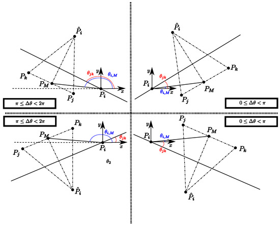
Figure 1.
TFA triangle construction cases. Time information has been omitted.
If the length of one of the edges in the triangle is greater than twice the desired distance between aircraft, then the desired position is computed as:
in order to approach the vehicles before creating the triangle-based formation. The procedure is summarized in Algorithm 1.
| Algorithm 1:Triangular Formation Algorithm (Time information has been omitted). |
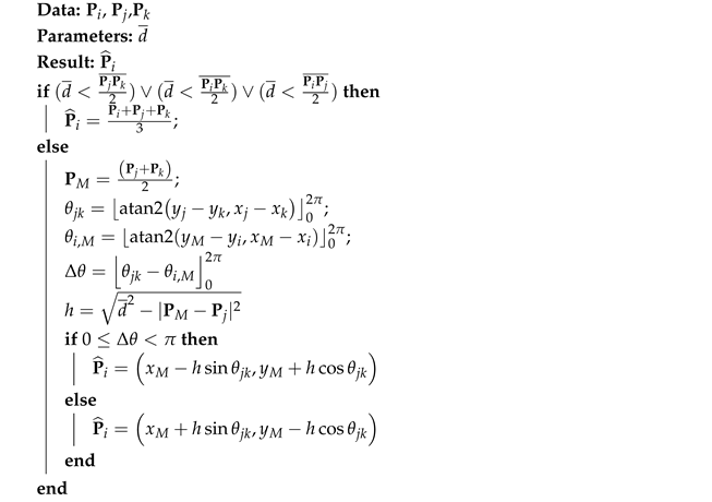 |
4. The Distributed Guidance System
Figure 2, shows the common architecture of the Guidance Algorithm of each aircraft that is composed of the following elements.

Figure 2.
Generalized Scheme of the Guidance Algorithm (Time information has been omitted).
- -
- A Swarm Awareness Algorithm (SAA) devoted to computing the neighbors set , needed to execute the Swarm Control Algorithm.
- -
- A Swarm Control Algorithm (SCA) aimed at calculating the next desired position and speed , at each time instant, in order to reach the target area at and keep the aircraft within the formation.
- -
- A Collision Avoidance Algorithm (CAA) that modifies the reference signal for the Trajectory Tracking Algorithm, and , in order to avoid collision with the obstacles and the adjacent vehicles.
- -
- A Trajectory Tracking Algorithm (TTA) that computes the control signals and to be supplied to the FCS.
4.1. The Swarm Awareness Algorithm
At any time t, the swarm topology can be described by a direct weighted graph , whose node set is composed by the vehicles , whereas the edges are set by
where is the set of neighbour (adjacent) vertices to node i. At each arc is associated a weight equal to the distance between the node i and the node j: .
On the basis of information received by the other vehicles, the SAA builds the i-th row of the adjacency matrix of the graph.
Therefore, for each vehicle j, with and , the line of sight vector between the vehicle i and j is defined as . With reference to the , consider the following angle :
where
- the operator wraps the angle to the interval ,
- defined in the range ,
- , defined in the range .
At the time t, the set of all the vehicles neighboring the i-th UAV, by evaluating the angle :
The set is obtained by selecting the two nearest vehicles in the set on the basis of the actual distance .
4.2. The Swarm Control Algorithm
After the SAA, the SCA computes a reference direction , taking into account the target location and/or the desired point provided by TFA as follows:
where the constants and have properly defined values. In order to avoid undesired turns, thus assuring that the follower always flies towards the final target point, the desired position is constrained to be in the semi-plane containing and bounded by the perpendicular to the line connecting to . According to this:
The reference heading is then computed on the basis of reference direction as follows:
The reference speed must respect constraints on minimum and maximum speed and is computed as follows:
where
- and are the minimum and maximum allowable speeds;
- is the current distance from the next desired position ;
- is the actual heading;
- is the control algorithm sampling time;
- ;
- is the desired reference speed.
4.3. The Collision Avoidance and Trajectory Tracking Algorithms
The Collision Avoidance Algorithm must be designed to guarantee that every aircraft in the formation is able to avoid collisions with the other vehicles and/or possible obstacles or no-fly zones.
Consider fixed circular obstacles. Each j-th obstacle is modeled as a circumference of radius , centered at point . At any time t, for any fixed obstacle, is contained in the semi-plane , the CAA verifies if any distance from the obstacles is less than the prescribed safety distance .
At time t, the set of possible colliding obstacles is the following:
Since any generic vehicle j can also be described as a moving circular obstacle of radius and centered at point at time t, the CAA computes the set of colliding aircraft as follows:
Once the set and have been computed, only the nearest colliding obstacle is considered [2,59].
Without a loss of generality, assume that the nearest collision occurs with the obstacle .
The reference signals for the tracking system are the following:
where
- -
- is provided by the Swarm Control Algorithm,
- -
- ,
- -
- and are the direction of tangent to the obstacles in modified by the term in order to allow the aircraft to leave the circumference of radius ,
- -
- (see Figure 3).
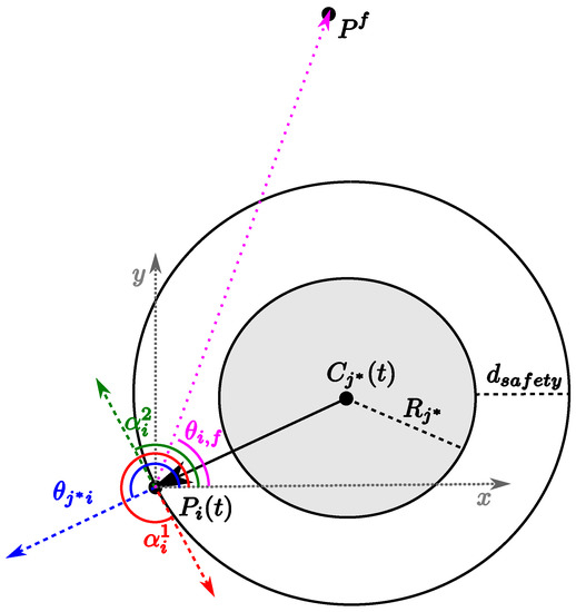 Figure 3. Collision avoidance angles definition (Time information has been omitted). For example, with .
Therefore, is equal to the angle provided by the SCA, if this direction allows collision avoidance with the obstacle, otherwise it is chosen in order to minimize deviation from the direction pointing to the target point .
If the colliding obstacle is fixed, the reference speed to be passed to the tracking system, , is assumed to be equal to ; if the collision occurs with another vehicle, the reference speed, , is computed by taking into account the difference between the desired and the current heading:
According to the Proportional Navigation (PN) approach, whose stability is proven in [60,61,62,63,64], the commanded turn rate is proportional to the error between the current heading and the desired one :
Analogously, the commanded longitudinal acceleration is proportional to the error between the current speed and the desired one :
where and are suitable constants. To consider aircraft performance limits, the control signal is saturated as .
5. The Proposed SCA Schemes
On the basis of Section 4, three different architectures can be defined, namely:
- Fixed Leader–Follower SCA;
- Free Leader–Follower SCA;
- No Leader SCA;
5.1. Fixed Leader–Follower SCA
The Fixed leader–follower scheme is shown in Figure 4. In this scheme, the swarm topology is considered preassigned and cannot change during flight. Consequently, the graph cannot change its structure. On the other hand, even if the mutual distance between the aircraft can change in time, the neighbors set of each UAV i is considered to be assigned. Consequently, the SAA is not involved in computing the neighbors set , since this set is time-invariant of the fleet topology.
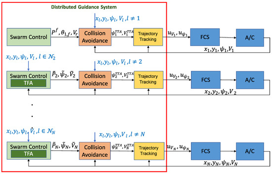
Figure 4.
Distributed Guidance system based on leader–follower architecture (Time information has been omitted). The first row represents the Leader Guidance algorithm, whereas the following rows are related to the other vehicles (followers) in the swarm.
In this scheme, we consider that the neighbors set of the leader, denoted by index , has cardinality equal to 0 (), whereas the followers, , are connected with two vehicles of the fleet.
Since , the leader plans its desired trajectory to reach the target location avoiding obstacles. Therefore, for the leader, the constants and in Equation (6) are set equal to zero and different from zero, respectively. The followers’ guidance system is based on TFA. Being the swarm structure preassigned, each follower, taking into account the expected position of neighboring vehicles, computes its own desired position . For the follower, the constant , in Equation (6), is different from zero, whereas the constant is set equal to zero.
5.2. Free Leader–Follower SCA
To have more flexibility, a decentralized algorithm should be able to auto-select one or more leaders to form sub swarms if, for example, an obstacle is encountered. In this case, a so-called Swarm Awareness Algorithm is needed to determine the role of each aircraft in the swarm and identify its nearest neighbors to be used for the TFA. Figure 5 shows the general guidance system architecture.
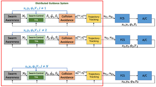
Figure 5.
Free leader–follower control scheme (Time information has been omitted).
If the cardinality of set is equal to 0, the vehicle acts as a leader, pointing towards the final point , and the constants and in Equation (6) are chosen equal to zero and different from zero, respectively.
If the cardinality of the set is equal to or greater than 1, the aircraft acts as a follower. Consequently, the SCA computes the next desired position by using the TFA, in Equation (6), constant is assumed different from zero, whereas constant is set equal to zero.
5.3. No Leader SCA
As an alternative to the leader–follower strategy, a full decentralized scheme (shown in Figure 6) can be defined by combining the contributions of two different controllers, one devoted to the maintenance of the flight formation, the other dedicated to the target tracking.

Figure 6.
Decentralized control system architecture based on No Leader SCA (Time information has been omitted).
Therefore, both constants and in Equation 6 are set different from zero.
6. Numerical Results
To test and compare the three proposed guidance algorithms (see Section 4), several numerical simulations were performed on four different scenarios using an ad-hoc simulator developed in Matlab. Such operational scenarios are represented in a box of km and present different sets of obstacles. The objective is to define simulation environments compliant with formations of micro/mini quadrotor-type UAVs [65] with 10–15 min of flight endurance.
The simulation parameters are resumed in Table 1. Initial conditions were assigned such that the formation starts from an assigned graph, being not in equilibrium. However, we repeated the execution 10 times for each scenario, starting from different initial conditions, to compute the averaged performance indices not depending on an arbitrary starting point.

Table 1.
Simulation parameters.
Each scenario is executed considering formations of 3, 4, 5, 7, 10 and 20 aircraft. The results are resumed by comparing trajectories obtained in a specific configuration using the three proposed control schemes and by computing some performance indices in order to evaluate the algorithm effectiveness. In particular, we computed the mean distance, , between every pair of visible aircraft in the formation graph, the maximum and minimum distances, and , between each pair of vehicles in the swarm:
where is the set of mutual distances between all couples of aircraft computed at time t:
Another performance index can be defined by considering that the formation cooperatively tries to solve a packing problem without a prescribed external boundary. The triangular mesh generated by vehicles should tend to a hexagonal packing that represents the most efficient one in terms of the occupied area. The packing density can be measured as the ratio between the sum of areas of N circles with a radius equal to the desired distance and the average area occupied by the formation during the flight. The hexagonal packing density represents a maximum, but in our problem, circles can be overlapped, i.e., aircraft may have mutual distances shorter than the desired one. For this reason, the density can reach values near or greater than 1.
6.1. Scenario #1
Scenario #1 consists of three circular objects of different sizes placed between the starting and the target point.
Figure 7 shows the results in terms of UAVs trajectories obtained by using the three proposed guidance algorithms with three aircraft. The positions reached by UAVs at different time steps are also marked to highlight the formation mesh during flight. Green solid lines indicate the obtained formation graph.
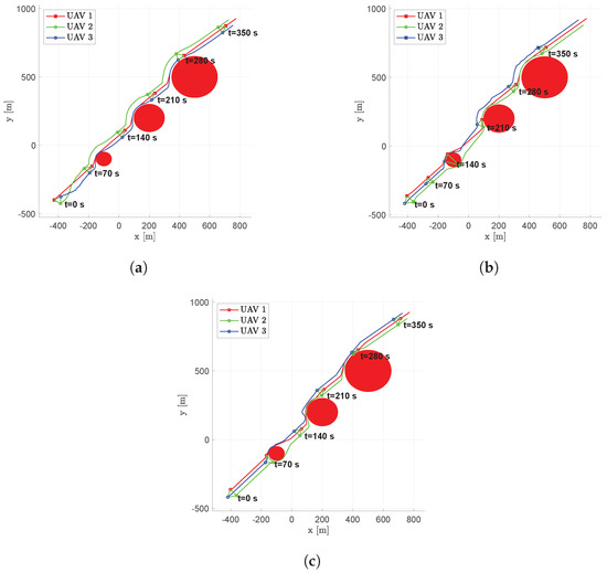
Figure 7.
Scenario #1—3 aircraft: UAVs trajectories. Obstacles are represented in red, colored circular markers indicate the positions of followers at different time instants, whereas colored square markers are for the leader. Green straight lines are used to highlight the connection graph. (a) Fixed leader–follower SCA. (b) Free leader–follower SCA. (c) No Leader SCA.
Although UAVs are forced to change their trajectory near obstacles in all the simulations, they are able to re-establish the triangular formation with all three of the proposed approaches.
Figure 8 shows the distances of vehicle 1 in respect to the other aircraft. Solid lines indicate distances with neighboring vehicles, while dashed lines highlight non-adjacent UAVs. In the fixed leader scheme, UAV 1 is the leader that, according to the proposed architecture, points to the target, while followers try to realize the triangle-based formation. The free leader scheme does not prescribe a fixed leader, leaving aircraft to choose their own role. For this reason, UAV 1 does not always act as the leader, sometimes by applying TFA with UAV 2. Near obstacles, the distances increase as a result of the formation spreading, decreasing after them. The no leader scheme is totally distributed without a leader. Every vehicle points toward the target while maintaining the triangle-based formation. Trajectories pass nearer to the obstacles as a result of the target tracking.
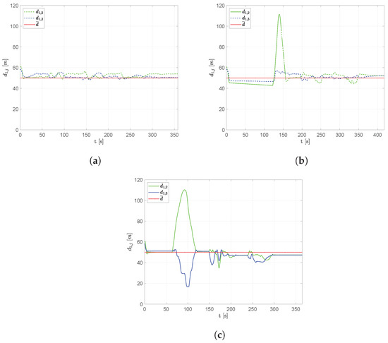
Figure 8.
Scenario #1—3 aircraft: distances between UAV 1 and the other swarm vehicles. Solid lines are used for neighboring vehicles, dashed lines indicate the absence of the arc in the connection graph. The desired distance is highlighted using a dotted red line. (a) Fixed leader–follower SCA. (b) Free leader–follower SCA. (c) No Leader SCA.
Figure 9 shows the average distance obtained during simulation, using Equation (16). It is possible to notice that the fixed leader architecture tends to maintain a more compact triangular flight formation in the presence of obstacles, unlike the free leader and no leader schemes that allow the aircraft to spread out when passing around the obstacles.
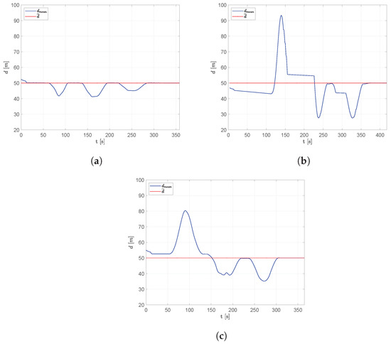
Figure 9.
Scenario #1—3 aircraft: average distance between adjacent aircraft compared to the desired distance. (a) Fixed leader–follower SCA. (b) Free leader–follower SCA. (c) No Leader SCA.
Figure 10, Figure 11 and Figure 12 show the results obtained in the same scenario with a formation of 10 vehicles. Looking at the trajectories, it is evident that the capability of the fixed leader scheme to maintain a more compact flight formation and to avoid the spreading while passing the obstacles.
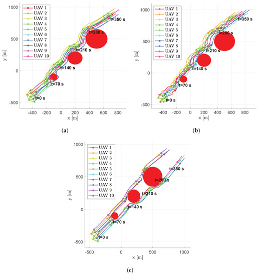
Figure 10.
Scenario #1—10 aircraft: UAV’s trajectories. Obstacles are represented in red, colored circular markers indicate positions of followers at different time instants, whereas colored square markers are for the leader. Green straight lines are used to highlight the connection graph. (a) Fixed leader–follower SCA. (b) Free leader–follower SCA. (c) No Leader SCA.
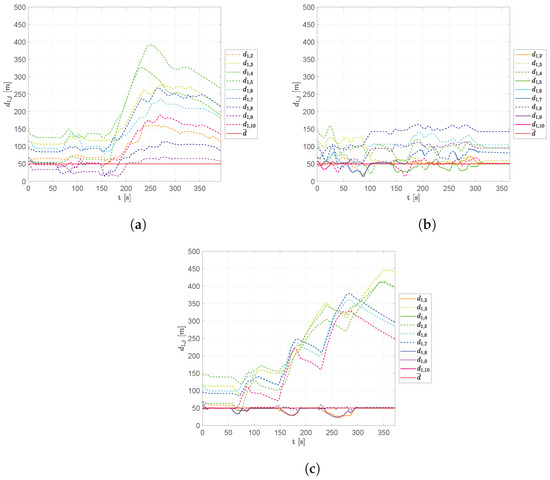
Figure 11.
Scenario #1—10 aircraft: distances between UAV 1 and the other swarm vehicles. Solid lines are used for neighboring vehicles, dashed lines indicate the absence of the arc in the connection graph. The desired distance is highlighted using a dotted red line. (a) Fixed leader–follower SCA. (b) Free leader–follower SCA. (c) No Leader SCA.
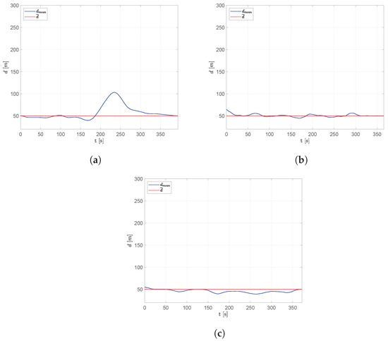
Figure 12.
Scenario #1—10 aircraft: average distance between adjacent aircraft compared with desired distance. (a) Fixed leader–follower SCA. (b) Free leader–follower SCA. (c) No Leader SCA.
As shown in Figure 12, the distance between aircraft tends to remain around the desired value, , though large deviations can clearly be observed close to the obstacles. Since the algorithm is decentralized, each vehicle takes its own obstacle-avoidance strategy, forcing the remaining formation to adapt. The displacement of the aircraft, moving from their starting position and approaching the desired flight formation, is quite clear in the initial phase of the simulations.
Scenario #1 was used to perform simulations with 3, 4, 5, 7, 10 and 20 vehicles. Figure 13 shows the results in terms of average, minimum and maximum distances , and . It shows that the SCA and the collision avoidance strategy are effective, being and in every configuration.
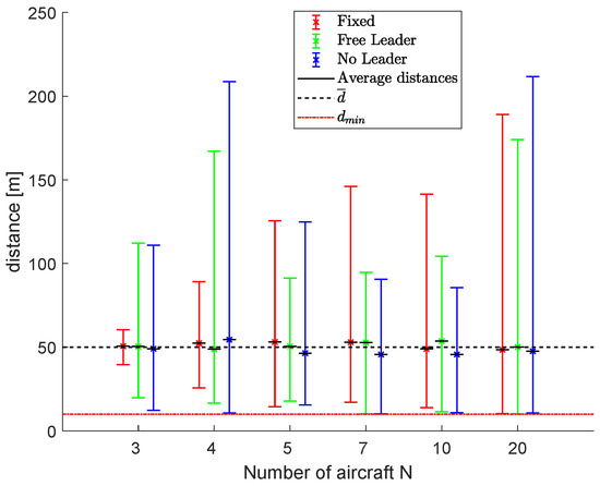
Figure 13.
Scenario #1: Results in terms of average, minimum and maximum distances, , and .
Figure 14 shows the results in terms of packing densities, considering formations of 3, 4, 5, 7, 10 and 20 aircraft. The average, minimum and maximum densities are indicated by using bars to highlight algorithms’ performance during the flight. This figure proves that the fixed leader scheme makes the flight formation more compact, followed by the free leader scheme. The no leader scheme suffers from a greater aircraft separation in several sub-swarms, affecting the packing density.
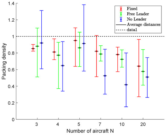
Figure 14.
Scenario #1: Packing densities. Bars indicate minimum and maximum values during the simulation. Values close to 1 indicate the maximum efficiency in the packing problem, i.e., a compact fleet with the desired mutual distances.
6.2. Scenario #2
Scenario #2 consists of four large obstacles placed between the starting and the target points. The positions of the obstacles were chosen in order to spread the swarm with a first big obstacle, before passing through a narrow channel formed by two nearby large circular objects. After that, the last obstacle forces the formation to spread again before reaching the target point. This scenario was built to stress the capability of the swarm to rendezvous after the spreading.
Figure 15 shows the trajectories of a flight formation made up of 7 UAVs. Scenario #2 confirms the previous results, where the fixed leader architecture tends to make the flight formation more compact in the presence of obstacles, forcing aircraft to always maintain the same connecting graph (Figure 15a), while the free leader and no leader schemes allow aircraft to spread around the obstacles (Figure 15b,c). In this case, the ability of the no leader scheme to create independent sub-swarms is more evident, and the formation rendezvous after the first obstacle is not completely achieved, being a sub-fleet of two vehicles passing outside the narrow channel.
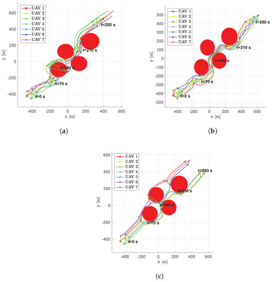
Figure 15.
Scenario #2—7 aircraft: UAVs trajectories. Obstacles are represented in red, colored circular markers indicate positions of followers at different time instants, whereas colored square markers are for the leader. Green straight lines are used to highlight the connection graph. (a) Fixed leader–follower SCA. (b) Free leader–follower SCA. (c) No Leader SCA.
Aircraft change their trajectories near obstacles but, once passed, they are able to re-establish the triangular mesh with all of the three proposed approaches. Similar to the previous scenario, there is an initial transient phase during which aircraft move from their starting position and approach to form the desired flight formation.
Some oscillations can be observed in the trajectories, even far from the obstacles, that are better damped in the no leader scheme. More smoothed trajectories result though the rendezvous after obstacles appears clearly delayed due to the target tracking contribution in the controller (Figure 15c).
Scenario #2 was used to perform simulations with 3, 4, 5, 7, 10 and 20 vehicles. Figure 16 shows the results in terms of average, minimum and maximum distances, , and . is always higher than the minimum required for all the three control strategies in every configuration, thanks to the collision avoidance strategy.
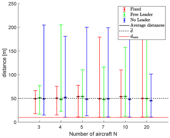
Figure 16.
Scenario #2: Results in terms of average, minimum and maximum distances, , and .
Packing densities obtained by the proposed schemes are resumed in Figure 17 for formations of 3, 4, 5, 7, 10 and 20 aircraft. The average, minimum and maximum densities are indicated by using bars to highlight algorithms’ performance during the flight. Again, the fixed leader scheme is more efficient in terms of packing, followed by the free leader scheme.
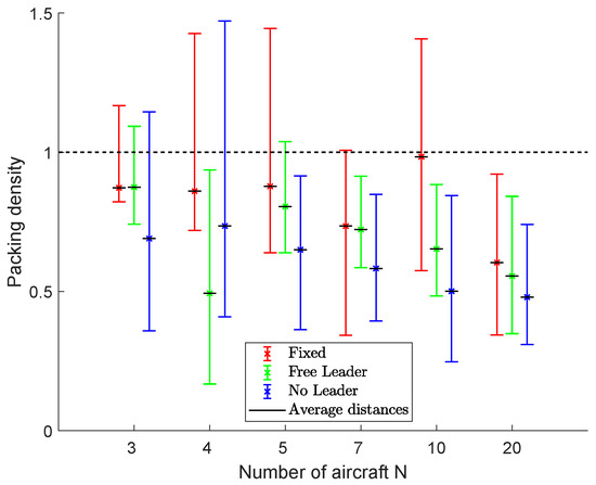
Figure 17.
Scenario #2: Packing densities. Bars indicate minimum and maximum values during the simulation. Values close to 1 indicate the maximum efficiency in the packing problem, i.e., a compact fleet with the desired mutual distances.
6.3. Scenario #3
Scenario #3 consists of three large obstacles and a group of small nearby objects placed between the starting and the target point. In Figure 18, the trajectories of a 20-UAV fleet, obtained by using the three proposed guidance algorithms, are shown. To highlight the swarm status during time, the positions reached by the UAVs at different time steps are marked. At the beginning of the simulation, the fleet is forced to pass through a narrow channel created by the first two large obstacles. Then, the formation must pass through a group of several small objects that stress the Collision Avoidance Algorithm. After that, a final large obstacle separates the fleet from the target point.
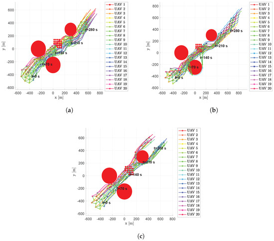
Figure 18.
Scenario #3—20 aircraft: UAV’s trajectories. Obstacles are represented in red, colored circular markers indicate positions of followers at different time instants, whereas colored square markers are for the leader. Green straight lines are used to highlight the connection graph. (a) Fixed leader–follower SCA. (b) Free leader–follower SCA. (c) No Leader SCA.
Scenario #3 confirms the previous results, where the fixed leader architecture tends to make the flight formation more compact in the presence of obstacles, forcing the aircraft to always maintain the same connecting graph, while the free leader and no leader schemes allow aircraft to spread around the obstacles.
Although aircraft change their trajectory near obstacles, they are able to re-establish the triangular mesh with all the three proposed approaches. As in Scenario #2, it is clear that both the fixed leader and free leader scheme have less smooth trajectories due to the fact that the aircraft always tend to chase each other. This behavior further stresses the Collision Avoidance Algorithm far from obstacles. The no leader scheme provides more regular (straight) trajectories thanks to the damping factor given by the target tracking contribution in the controller. On the other hand, as in the previous scenario, with a greater number of aircraft shown in Figure 18, sub-swarms created to overcome obstacles fail to meet again downstream from the last one (Figure 18c). Anyway, the minimum distance between aircraft never falls below the minimum required value (, regardless of the swarm control scheme used. For the sake of clarity, Figure 19 shows the results in terms of average, minimum and maximum distances, , and , using fleets of 3, 4, 5, 7, 10 and 20 UAVs.
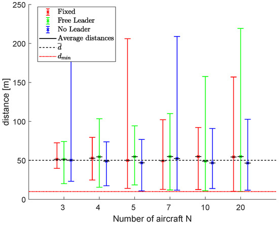
Figure 19.
Scenario #3: Results in terms of average, minimum and maximum distances, , and .
Figure 20 shows the results in terms of packing densities for fleets of 3, 4, 5, 7, 10 and 20 aircraft. The average, minimum and maximum densities are indicated by using bars to highlight algorithms’ performance during the flight. In this scenario, the no leader scheme is not always the worst one in terms of packing density, even if the presence of the last big obstacle avoids a fast rendezvous at the end of the simulation.
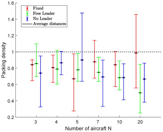
Figure 20.
Scenario #3: Packing densities. Bars indicate minimum and maximum values during the simulation. Values close to 1 indicate the maximum efficiency in the packing problem, i.e., a compact fleet with the desired mutual distances.
6.4. Scenario #4
To analyze the formation behavior when it is necessary to make the entire fleet to follow the target, Scenario #4 considers a target moving from an initial position , with a cruise speed m/s and a heading angle . Some static obstacles are also present in the scenario to increase the challenge. Figure 21 shows the results in terms of trajectories of a 7-UAV fleet. Being very far from the fleet, the target is not represented in the figure.
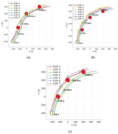
Figure 21.
Scenario #4—7 aircraft: UAV’s trajectories. Obstacles are represented in red, colored circular markers indicate positions of followers at different time instants, whereas colored square markers are for the leader. Green straight lines are used to highlight the connection graph. (a) Fixed leader–follower SCA. (b) Free leader–follower SCA. (c) No Leader SCA.
The ability of the no leader scheme to create sub-swarms is highlighted again. After the first obstacle, two separated sub-fleets were created that find a rendezvous only after the final obstacle. Figure 22 shows the results in terms of average, minimum and maximum distances, , and , using fleets of 3, 4, 5, 7, 10 and 20 UAVs. The minimum distance is always guaranteed to be greater than the assigned safety distance , while the average distance between neighboring vehicles is near the desired .
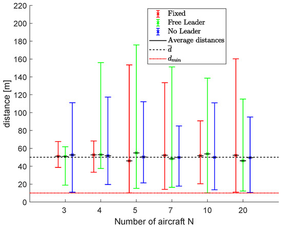
Figure 22.
Scenario #4: Results in terms of average, minimum and maximum distances, , and .
Figure 23 shows the results in terms of packing densities for fleets of 3, 4, 5, 7, 10 and 20 aircraft. The average, minimum and maximum densities are indicated by using bars to highlight algorithms’ performance during the flight.
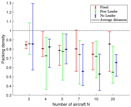
Figure 23.
Scenario #4: Packing densities. Bars indicate minimum and maximum values during the simulation. Values close to 1 indicate the maximum efficiency in the packing problem, i.e., a compact fleet with the desired mutual distances.
7. Conclusions
In this paper, three decentralized guidance systems based on different UAV formation control schemes are presented. The first two are based on a “leader–follower” swarm control algorithm, while the third one does not require the definition of any leader so that all the swarm vehicles follow the target and simultaneously maintain the shape of the flight formation.
Each aircraft computes its own desired position in the swarm by using the Triangular Formation Algorithm, and consequently, the UAV swarm shape appears like a triangular mesh. To avoid any possible collision between aircraft or with any obstacles, a Collision Avoidance Algorithm has been implemented in the guidance control system, based on a modified potential field approach.
To test the effectiveness of the proposed swarm control system, different operational scenarios have been defined involving an increasing number of air vehicles. The results obtained show that all of the proposed guidance algorithms work properly with some peculiar characteristics, in particular:
- The fixed leader and free leader schemes provide less smooth trajectories. Oscillations are clearly observed, even around the steady-state condition, that are better damped in the no leader scheme; this result is strictly related to the SCA operating philosophy according to which, whenever a leader is present, followers are forced to follow a point that is at a distance comparable with the TFA triangular elements, whereas in the no leader scheme, they point to the target and are less affected by the positions of their neighboring vehicles.
- Near obstacles, the mutual distances among aircraft tend to increase, being very different from the desired value; however, some differences can be observed: the fixed leader architecture makes the flight formation more compact, forcing aircraft to maintain the formation shape for a longer time, while the free leader and no leader schemes allow the spreading of the formation near obstacles. It is worth noticing that the no leader architecture not only provides more regular (straight) trajectories, but it allows faster recovery of the desired distances once the obstacle is passed compared to the free leader scheme. In such a case, in fact, the selection process of the leader tends to delay the air vehicle’s rendezvous after the flight formation spreads in the presence of obstacles.
- However, as the number of vehicles increases, the no leader scheme has a draw-back: as shown in Scenario #3, sub-swarms are not able to meet again after passing the obstacle. This is due to the fact that each aircraft applies TFA with the two nearest vehicles present both ahead and behind, not following a leader but rather pointing to the target. On the other hand, in the free-leader scheme, only vehicles present forward are taken into account, reducing the number of possible edges in the mesh and resulting in increasing importance of vehicles marked as leaders guiding the followers to the target.
Author Contributions
Conceptualization, E.D. and I.N.; Data curation, S.R.B., E.D. and I.N.; Formal analysis, L.B., E.D. and I.N.; Funding acquisition, L.B. and M.M.; Investigation, S.R.B., E.D. and I.N.; Methodology, E.D. and I.N.; Resources, L.B. and M.M.; Software, E.D. and I.N.; Supervision, M.M.; Validation, S.R.B.; Visualization, S.R.B.; Writing—original draft, L.B., E.D. and I.N.; Writing—review & editing, L.B., E.D., M.M. and I.N. All authors have read and agreed to the published version of the manuscript.
Funding
This research received no external funding.
Conflicts of Interest
The authors declare no conflict of interest.
Abbreviations
The following abbreviations are used in this manuscript:
| TFA | Triangular Formation Algorithm |
| UAV | Unmanned Aerial Vehicle |
| SGA | Swarm Guidance Algorithm |
| CAA | Collision Avoidance Algorithm |
| TTA | Trajectory Tracking Algorithm |
| FCS | Flight Control System |
| SAA | Swarm Awareness Algorithm |
| SCA | Swarm Control Algorithm |
References
- Dudek, G.; Jenkin, M.; Milios, E.; Wilkes, D. A taxonomy for multi-agent robotics. Auton. Robot. 1996, 3, 374–397. [Google Scholar] [CrossRef]
- Cao, Y.U.; Fukunaga, A.S.; Kahng, A. Cooperative mobile robotics: Antecedents and directions. Auton. Robot. 1997, 4, 7–27. [Google Scholar] [CrossRef]
- Schneider-Fontan, M.; Mataric, M. Territorial multi-robot task division. IEEE Trans. Robot. Autom. 1998, 14, 815–822. [Google Scholar] [CrossRef] [Green Version]
- Maza, I.; Ollero, A.; Casado, E.; Scarlatti, D. Classification of Multi-UAV Architectures. In Handbook of Unmanned Aerial Vehicles; Valavanis, K.P., Vachtsevanos, G.J., Eds.; Springer: Dordrecht, The Netherlands, 2015; pp. 953–975. [Google Scholar] [CrossRef]
- Kushleyev, A.; Mellinger, D.; Powers, C.; Kumar, V. Towards a swarm of agile micro quadrotors. Auton. Robot. 2013, 35, 287–300. [Google Scholar] [CrossRef]
- Cicala, M.; D’Amato, E.; Notaro, I.; Mattei, M. Distributed UAV State Estimation in UTM context. In Proceedings of the 2019 6th International Conference on Control, Decision and Information Technologies (CoDIT), Paris, France, 23–26 April 2019; pp. 557–562. [Google Scholar]
- D’Amato, E.; Notaro, I.; Mattei, M.; Tartaglione, G. Attitude and position estimation for an UAV swarm using consensus Kalman filtering. In Proceedings of the 2015 IEEE Metrology for Aerospace (MetroAeroSpace), Benevento, Italy, 4–5 June 2015; pp. 519–524. [Google Scholar]
- D’Amato, E.; Nardi, V.A.; Notaro, I.; Scordamaglia, V. A Particle Filtering Approach for Fault Detection and Isolation of UAV IMU Sensors: Design, Implementation and Sensitivity Analysis. Sensors 2021, 21, 3066. [Google Scholar] [CrossRef] [PubMed]
- Elmokadem, T.; Savkin, A.V. Computationally-Efficient Distributed Algorithms of Navigation of Teams of Autonomous UAVs for 3D Coverage and Flocking. Drones 2021, 5, 124. [Google Scholar] [CrossRef]
- Hildmann, H.; Kovacs, E.; Saffre, F.; Isakovic, A. Nature-inspired drone swarming for real-time aerial data-collection under dynamic operational constraints. Drones 2019, 3, 71. [Google Scholar] [CrossRef] [Green Version]
- Xu, C.; Zhang, K.; Jiang, Y.; Niu, S.; Yang, T.; Song, H. Communication Aware UAV Swarm Surveillance Based on Hierarchical Architecture. Drones 2021, 5, 33. [Google Scholar] [CrossRef]
- Guo, X.; Lu, J.; Alsaedi, A.; Alsaadi, F.E. Bipartite consensus for multi-agent systems with antagonistic interactions and communication delays. Phys. A Stat. Mech. Appl. 2018, 495, 488–497. [Google Scholar] [CrossRef]
- Lee, W.; Kim, D. Autonomous shepherding behaviors of multiple target steering robots. Sensors 2017, 17, 2729. [Google Scholar] [CrossRef] [PubMed] [Green Version]
- Forestiero, A. Bio-inspired algorithm for outliers detection. Multimed. Tools Appl. 2017, 76, 25659–25677. [Google Scholar] [CrossRef]
- Wang, J.; Ahn, I.S.; Lu, Y.; Yang, T.; Staskevich, G. A distributed estimation algorithm for collective behaviors in multiagent systems with applications to unicycle agents. Int. J. Control Autom. Syst. 2017, 15, 2829–2839. [Google Scholar] [CrossRef]
- Olfati-Saber, R. Flocking for multi-agent dynamic systems: Algorithms and theory. IEEE Trans. Autom. Control 2006, 51, 401–420. [Google Scholar] [CrossRef] [Green Version]
- Su, H.; Wang, X.; Lin, Z. Flocking of multi-agents with a virtual leader. IEEE Trans. Autom. Control 2009, 54, 293–307. [Google Scholar] [CrossRef]
- Sun, F.; Turkoglu, K. Distributed real-time non-linear receding horizon control methodology for multi-agent consensus problems. Aerosp. Sci. Technol. 2017, 63, 82–90. [Google Scholar] [CrossRef] [Green Version]
- Bassolillo, S.R.; D’Amato, E.; Notaro, I.; Blasi, L.; Mattei, M. Decentralized mesh-based model predictive control for swarms of UAVs. Sensors 2020, 20, 4324. [Google Scholar] [CrossRef]
- Jafari, M.; Xu, H. Biologically-inspired intelligent flocking control for networked multi-UAS with uncertain network imperfections. Drones 2018, 2, 33. [Google Scholar] [CrossRef] [Green Version]
- Krick, L.; Broucke, M.E.; Francis, B.A. Stabilisation of infinitesimally rigid formations of multi-robot networks. Int. J. Control 2009, 82, 423–439. [Google Scholar] [CrossRef]
- Tian, Y.P.; Wang, Q. Global stabilization of rigid formations in the plane. Automatica 2013, 49, 1436–1441. [Google Scholar] [CrossRef]
- Anderson, B.D.; Yu, C.; Fidan, B.; Hendrickx, J.M. Rigid graph control architectures for autonomous formations. IEEE Control Syst. Mag. 2008, 28, 48–63. [Google Scholar]
- Olfati-Saber, R.; Murray, R.M. Graph rigidity and distributed formation stabilization of multi-vehicle systems. In Proceedings of the 41st IEEE Conference on Decision and Control, Las Vegas, NV, USA, 10–13 December 2002; Volume 3, pp. 2965–2971. [Google Scholar]
- Ren, W.; Atkins, E. Distributed multi-vehicle coordinated control via local information exchange. Int. J. Robust Nonlinear Control IFAC-Affil. J. 2007, 17, 1002–1033. [Google Scholar] [CrossRef] [Green Version]
- Xiao, F.; Wang, L.; Chen, J.; Gao, Y. Finite-time formation control for multi-agent systems. Automatica 2009, 45, 2605–2611. [Google Scholar] [CrossRef]
- Jing, G.; Zheng, Y.; Wang, L. Consensus of multiagent systems with distance-dependent communication networks. IEEE Trans. Neural Networks Learn. Syst. 2016, 28, 2712–2726. [Google Scholar] [CrossRef] [PubMed]
- Fax, J.A.; Murray, R.M. Information flow and cooperative control of vehicle formations. IEEE Trans. Autom. Control 2004, 49, 1465–1476. [Google Scholar] [CrossRef] [Green Version]
- Coogan, S.; Arcak, M. Scaling the size of a formation using relative position feedback. Automatica 2012, 48, 2677–2685. [Google Scholar] [CrossRef]
- Olfati-Saber, R.; Fax, J.A.; Murray, R.M. Consensus and cooperation in networked multi-agent systems. Proc. IEEE 2007, 95, 215–233. [Google Scholar] [CrossRef] [Green Version]
- Wang, L.; Xiao, F. A new approach to consensus problems in discrete-time multiagent systems with time-delays. Sci. China Ser. Inf. Sci. 2007, 50, 625–635. [Google Scholar] [CrossRef]
- Wang, L.; Xiao, F. Finite-time consensus problems for networks of dynamic agents. IEEE Trans. Autom. Control 2010, 55, 950–955. [Google Scholar] [CrossRef]
- Reynolds, C.W. Flocks, herds and schools: A distributed behavioral model. In Proceedings of the 14th annual conference on Computer graphics and Interactive Techniques, Anaheim, CA, USA, 27–31 July 1987; pp. 25–34. [Google Scholar]
- Kosuge, K.; Sato, M. Transportation of a single object by multiple decentralized-controlled nonholonomic mobile robots. In Proceedings of the IEEE/RSJ International Conference on Intelligent Robots and Systems (IROS’99), Kyongju, Korea, 17–21 October 1999; Volume 3, pp. 1681–1686. [Google Scholar] [CrossRef]
- Bangash, Z.A.; Sanchez, R.P.; Ahmed, A.; Khan, M.J. Aerodynamics of Formation Flight. J. Aircr. 2006, 43, 907–912. [Google Scholar] [CrossRef]
- Ariola, M.; Mattei, M.; D’Amato, E.; Notaro, I.; Tartaglione, G. Model predictive control for a swarm of fixed wing uavs. In Proceedings of the 30th Congress of the International Council of the Aeronautical Sciences, ICAS, Daejeon, Korea, 25–30 September 2016. [Google Scholar]
- Yun, B.; Chen, B.M.; Lum, K.Y.; Lee, T.H. Design and implementation of a leader-follower cooperative control system for unmanned helicopters. J. Control Theory Appl. 2010, 8, 61–68. [Google Scholar] [CrossRef]
- Bayraktar, S.; Fainekos, G.; Pappas, G. Experimental cooperative control of fixed-wing unmanned aerial vehicles. In Proceedings of the 2004 43rd IEEE Conference on Decision and Control (CDC) (IEEE Cat. No.04CH37601), Nassau, Bahamas, 14–17 December 2004; Volume 4, pp. 4292–4298. [Google Scholar] [CrossRef]
- Paul, T.; Krogstad, T.R.; Gravdahl, J.T. Modelling of UAV formation flight using 3D potential field. Simul. Model. Pract. Theory 2008, 16, 1453–1462. [Google Scholar] [CrossRef]
- Dasgupta, P. A Multiagent Swarming System for Distributed Automatic Target Recognition Using Unmanned Aerial Vehicles. IEEE Trans. Syst. Man Cybern. Part A Syst. Humans 2008, 38, 549–563. [Google Scholar] [CrossRef]
- D’Amato, E.; Mattei, M.; Notaro, I. Bi-level flight path planning of UAV formations with collision avoidance. J. Intell. Robot. Syst. 2019, 93, 193–211. [Google Scholar] [CrossRef]
- Fuchs, C.; Borst, C.; de Croon, G.C.; Van Paassen, M.; Mulder, M. An ecological approach to the supervisory control of UAV swarms. Int. J. Micro Air Veh. 2014, 6, 211–229. [Google Scholar] [CrossRef] [Green Version]
- Han, K.; Lee, J.; Kim, Y. Unmanned aerial vehicle swarm control using potential functions and sliding mode control. Proc. Inst. Mech. Eng. Part G J. Aerosp. Eng. 2008, 222, 721–730. [Google Scholar] [CrossRef]
- Modares, J.; Mastronarde, N.; Dantu, K. Simulating Unmanned Aerial Vehicle swarms with the UB-ANC emulator. Int. J. Micro Air Veh. 2019, 11, 1756829319837668. [Google Scholar] [CrossRef] [Green Version]
- Sanchez-Aguero, V.; Valera, F.; Vidal, I.; Tipantuña, C.; Hesselbach, X. Energy-Aware Management in Multi-UAV Deployments: Modelling and Strategies. Sensors 2020, 20, 2791. [Google Scholar] [CrossRef]
- Parker, L. ALLIANCE: An architecture for fault tolerant multirobot cooperation. IEEE Trans. Robot. Autom. 1998, 14, 220–240. [Google Scholar] [CrossRef] [Green Version]
- Gerkey, B.P.; Matarić, M.J. A Formal Analysis and Taxonomy of Task Allocation in Multi-Robot Systems. Int. J. Robot. Res. 2004, 23, 939–954. [Google Scholar] [CrossRef] [Green Version]
- Viguria, A.; Maza, I.; Ollero, A. Distributed Service-Based Cooperation in Aerial/Ground Robot Teams Applied to Fire Detection and Extinguishing Missions. Adv. Robot. 2010, 24, 1–23. [Google Scholar] [CrossRef] [Green Version]
- Hsieh, M.A.; Cowley, A.; Keller, J.F.; Chaimowicz, L.; Grocholsky, B.; Kumar, V.; Taylor, C.J.; Endo, Y.; Arkin, R.C.; Jung, B.; et al. Adaptive teams of autonomous aerial and ground robots for situational awareness. J. Field Robot. 2007, 24, 991–1014. [Google Scholar] [CrossRef] [Green Version]
- Maza, I.; Caballero, F.; Capitan, J.; Martinez-de Dios, J.; Ollero, A. A distributed architecture for a robotic platform with aerial sensor transportation and self-deployment capabilities. J. Field Robot. 2011, 28, 303–328. [Google Scholar] [CrossRef] [Green Version]
- Li, X. A Triangular Formation Strategy for Collective Behaviors of Robot Swarm. In Computational Science and Its Applications—ICCSA 2009; Gervasi, O., Taniar, D., Murgante, B., Laganà, A., Mun, Y., Gavrilova, M.L., Eds.; Springer: Berlin/Heidelberg, Germany, 2009; Volume 5592, pp. 897–911. [Google Scholar] [CrossRef]
- Barnes, L.; Fields, M.; Valavanis, K. Unmanned ground vehicle swarm formation control using potential fields. In Proceedings of the 2007 Mediterranean Conference on Control Automation, Athens, Greece, 27–29 June 2007; pp. 1–8. [Google Scholar] [CrossRef]
- Beaulieu, A.; Givigi, S.N.; Ouellet, D.; Turner, J.T. Model-Driven Development Architectures to Solve Complex Autonomous Robotics Problems. IEEE Syst. J. 2018, 12, 1404–1413. [Google Scholar] [CrossRef]
- Anderson, B.D.; Yu, C.; Dasgupta, S.; Morse, A.S. Control of a three-coleader formation in the plane. Syst. Control Lett. 2007, 56, 573–578. [Google Scholar] [CrossRef]
- Cao, M.; Morse, A.S.; Yu, C.; Anderson, B.D.; Dasguvta, S. Controlling a triangular formation of mobile autonomous agents. In Proceedings of the 2007 46th IEEE Conference on Decision and Control, New Orleans, LA, USA, 12–14 December 2007; pp. 3603–3608. [Google Scholar]
- Cao, M.; Yu, C.; Anderson, B.D. Formation control using range-only measurements. Automatica 2011, 47, 776–781. [Google Scholar] [CrossRef] [Green Version]
- Wang, Q.; Hua, Q.; Chen, Z. Globally Exponentially Stable Triangle Formation Control of Multi-robot Systems. In Chinese Intelligent Systems Conference; Springer: Singapore, 2016; pp. 361–370. [Google Scholar]
- Dimarogonas, D.V.; Johansson, K.H. On the stability of distance-based formation control. In Proceedings of the 2008 47th IEEE Conference on Decision and Control, Cancun, Mexico, 9–11 December 2008; pp. 1200–1205. [Google Scholar]
- D’Amato, E.; Mattei, M.; Notaro, I. Distributed Reactive Model Predictive Control for Collision Avoidance of Unmanned Aerial Vehicles in Civil Airspace. J. Intell. Robot. Syst. 2020, 97, 185–203. [Google Scholar] [CrossRef]
- Agranovich, G.; Mery, Z. Lyapunov stability of proportional navigation guidance systems. Funct. Differ. Equ. 2017, 24, 3–12. [Google Scholar]
- Yanushevsky, R.; Boord, W. Lyapunov approach to guidance laws design. Nonlinear Anal. Theory Methods Appl. 2005, 63, e743–e749. [Google Scholar] [CrossRef]
- Gurfil, P.; Jodorkovsky, M.; Guelman, M. Finite time stability approach to proportional navigation systems analysis. J. Guid. Control Dyn. 1998, 21, 853–861. [Google Scholar] [CrossRef]
- Weiwen, Z.; Xiaogeng, L.; Xiaohong, J. Finite-time stability analysis of proportional navigation guidance system. In Proceedings of the 2010 IEEE International Conference on Intelligent Computing and Intelligent Systems, Xiamen, China, 29–31 October 2010; Volume 1, pp. 108–112. [Google Scholar]
- Yang, C.D.; Yeh, F.B.; Chen, J.H. The closed-form solution of generalized proportional navigation. J. Guid. Control Dyn. 1987, 10, 216–218. [Google Scholar] [CrossRef]
- Moschetta, J.M. The aerodynamics of micro air vehicles: Technical challenges and scientific issues. Int. J. Eng. Syst. Model. Simul. 2014, 6, 134–148. [Google Scholar] [CrossRef]
Publisher’s Note: MDPI stays neutral with regard to jurisdictional claims in published maps and institutional affiliations. |
© 2021 by the authors. Licensee MDPI, Basel, Switzerland. This article is an open access article distributed under the terms and conditions of the Creative Commons Attribution (CC BY) license (https://creativecommons.org/licenses/by/4.0/).